1
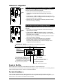
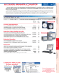
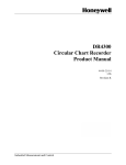
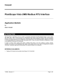
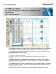
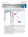
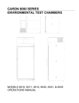
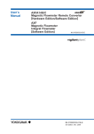
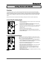
Getting Started with DR4300
Overview
The DR4300 recorder is a one-or two-pen microprocessor-based circular chart recorder providing reliable,
convenient pen-drawn analog traces on preprinted 10-inch charts. Chart speed and range are configurable. In
addition to generating pen-drawn chart traces, the DR4311 and DR4312 models include a display and keypad.
This option lets you display the real-time value of the process variable for each pen channel, as well as other
values.
Each pen channel has its own printed circuit assembly, allowing the channels to operate independently.
Connecting the Analog Inputs
• Open the recorder door. Loosen the captive screw in the chart plate
and swing the plate out.
TB2
• Locate terminal block TB2 on the right edge of the printed circuit
assembly for pen 1 (right side of the recorder).
• Insert the wires under the appropriate screws for the applicable input
type. Refer to Figure 2-9 in the Product Manual for specific input
actuation wiring.
• Tighten the screws to secure the wires.
• If the recorder has two pens, repeat these steps for the second
channel to TB2 on the pen 2 printed circuit assembly located on the
left side of the recorder.
Connecting Instrument Power
Separate recorder models are available for use with 100 Vac to 240
Vac or 20 Vdc to 27 Vdc power. (Refer to model number information in
Section 1 – Overview of the Product Manual.)
• Locate the power terminal block for your recorder model. Refer to
Figure 2-7 (Models without CE Mark) or 2-8 (Models with CE Mark) in
the Product Manual for your specific model type.
• Run power wires separately through conduit holes as indicated in
Figure 2-5 or 2-6 in the Product Manual.
• Strip 1/4-inch maximum of insulation from the end of each wire and
form end to fit under a screw connection.
• Install the power wires into the correct screw terminals, as
shown in Figure 2-7 or 2-8 in the Product Manual, to avoid
damaging the recorder.
Line Voltage Input
11/99
• Refer to document 51-52-05-01 for additional information concerning
noise interference prevention.
DR4300 Circular Chart Recorder – Quick Start Guide
44-01-25-16A
Instrument Configuration
For recorder models WITHOUT display and keypad
SW1
Configuration switches SW1 and input switches SW6 are provided on
each pen channel’s printed circuit assembly.
• Go to Table 3-2 in the Product Manual and find the desired
combination of recorder selections and input type for the pen 1
channel.
SW6
• Set the switches in SW1 and SW6, as indicated in Table 3-2 of the
Product Manual, for pen 1 on the printed circuit assembly on the right
side of the recorder. (Pen 1 is purple.)
• Repeat for pen 2 on its printed circuit assembly, located on the left
side of the recorder (if available).
For recorder models WITH display and keypad
Input switches SW6 are provided on each pen channel’s printed circuit
assembly.
• Go to Table 4-3 in the Product Manual and find the desired input
type for the pen 1 channel.
SW6
• Set the switches in SW6, as indicated in Table 4-3 of the Product
Manual, for pen 1 on the printed circuit assembly on the right side of
the recorder. (Pen 1 is purple.)
• Repeat for pen 2 on its printed circuit assembly, located on the left
side of the recorder (if available).
• Go to Table 4-4 in the Product Manual for the configuration
procedure. Refer to Figure 4-2 in the Product Manual for a
sequenced prompt hierarchy and to Tables 4-5 through 4-18 for
configuration parameter definitions.
Upper Display - four characters
Normal operation - Displays process variable (PV) for the selected input channel.
Configuration mode - Displays selection or parameter value.
Data displayed
is for input
Channel 1 or 2
Output relay 1 or 2
is ON, when lit.
Indicates temperature
units of PV on display.
INP
12
OUT 1 2
Lower Display - six characters
Normal operation - Displays selectable
operating parameter label and value.
With totalization, shows totalizer value.
Configuration mode - Displays Set Up
group and function parameters.
SET
UP
FUNC
DISP
MAN
AUTO
FC
MA
RL
Indicates controller mode:
M = Manual
A = Automatic
When either of the remote switch is set
for SP2, or when NumSPs = TWO
L = Setpoint 1 (SP) active
R = Setpoint 2 (S2) active
Otherwise, neither indicator is used.
Ready to Start Up
Refer to Table 3-5 or 4-22 in the Product Manual for procedure to set the chart time line.
Turn on the power to the instrument and it will start recording your input. For information on connecting the other
input and output options, refer to Section 2 in the Product Manual.
Technical Assistance
If you encounter a problem with your DR4300 recorder, you can receive technical assistance by dialing
1-800-423-9883 (USA and Canada). An engineer will discuss the problem with you. Please have your complete
model number, serial number, and software version available.
44-01-25-16A
DR4300 Circular Chart Recorder – Quick Start Guide
11/99