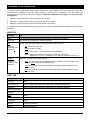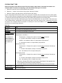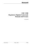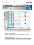
1
Honeywell
PlantScape Vista UMB Modbus RTU Interface
Application Bulletin
by
Glenn Heidel
INTRODUCTION
This document is intended for use as a guide to connecting Honeywell recorder/controller devices, such as UDC,
DR, DPR, UMC, VPR or VRX products, to a PlantScape Vista system using the Modbus RTU communication
protocol. This document covers the configuration of the parameters in the PlantScape system related to monitoring
or controlling Modbus RTU devices and their associated points. It does not discuss hardware configurations, wiring,
or any specifics for devices to be connected.
In order to monitor and/or control points within a Modbus RTU device, one must configure a project, channel,
controller and points on the PlantScape Vista system. This bulletin serves as an aide to configuring the required
information, especially regarding the addressing of the different entities to be configured.
REFERENCE DOCUMENTS
1. “Modbus RTU Serial Communication User Manual”; # 51-52-25-66
11/3/99 – Revision 1.1
Page 1 of 6
Modbus RTU Serial
Communications Link
PlantScape Vista
PROJECT CONFIGURATION
The Quick Builder tool will be used to perform the necessary configurations starting with the project file that contains
the configuration data for the generic interface. Upon creating a new project file (*.qdb) the Quick Builder tool will
present a set of tab cards in a window titled “Setup.” Data needs to be entered in three tab cards for a generic
Modbus RTU device; Channels, Controllers, and Points. Follow the steps below to properly set up the Project
configuration:
1. In the Channel tab card, the “Generic” (channel type) selection box must be checked. This will allow for
configuration of generic channels using the Modbus RTU protocol.
2. In the Controller tab card, the “Generic” (controller type) selection box must be checked. This will allow for
configuration of generic controllers using the Modbus RTU protocol.
3. In the Points tab card, both the “STATUS” and “ANALOG” (point types) selection boxes must be checked.
These selections will allow for configuration of all the point types required to monitor/control points supported in
the Modbus RTU protocol.
4. Once the tab cards in the “Setup” window are configure and the “OK” button is selected, the configurations will
be accepted and the Quick Builder main window will be exposed. The Project tab card should be selected and
in this tab card the user can enter a user-defined Project Name and (optional) project Description.
11/3/99 – Revision 1.1
Page 2 of 6
CHANNEL CONFIGURATION
The channel used by PlantScape Vista must be configured to use the Modbus RTU protocol with the correct data
communications parameters. Note that when setting up channel protocol parameters, they must match the
parameters of the physical device being configured. Follow the steps below to properly set up the Channel
configuration:
1. Select the Channel tab card in the Quick Builder main window.
2. Select the “+” button in the tool bar to bring up the “Add Items” window.
3. Select the “Generic” device type from the list and click the “OK” button.
A configuration window will be shown for the new channel. Configure the parameters in the Main and Port tab cards
as follows:
MAIN TAB
Parameter
Data
Name
User-chosen text string defining name of channel. ThisChannel for example.
Description
User-chosen text description of channel (optional).
Port
SERIAL port=com1 baud=38400 data=8 parity=none stop=1 write=3
(Example
followed by field
definitions)
port can also be com2, etc.
baud may also be 19200.
write should be set to 5 if baud=19200 or 3 if baud=38400.
NOTE: If the communications link contains a UDC2300, UDC3300,
DR4500 (ver. 57, 58) or a DR4300 (Ver. 4) the write delay must be set to 20.
Definition
UMB name=ThisChannel marg=25 fail=50
(Example
followed by field
definitions)
name is a user-chosen text string defining name of channel. This string must be the
same as Name parameter immediately above.
marg defines when communication channel’s condition becomes marginal. 25 is a
common value.
fail defines when the communication channel has failed and halts operation. 50 is a
common value.
PORT TAB
Parameter
Data
Port Type
Serial
Serial Port Name
COM1 or COM2. Must match that in Main tab’s Port parameter definition.
Baud Rate
19200 or 38400. Must match that in Main tab’s Port parameter definition.
Number of Data Bits
8
Stop Bits
1
Parity
NONE
Checksum
NONE
XON/XOFF
NONE
RS-232
All boxes unchecked
RS-485
All boxes unchecked
11/3/99 – Revision 1.1
Page 3 of 6
CONTROLLER CONFIGURATION
Controller parameters must be configured such that the PlantScape system recognizes the device as a generic,
Modbus RTU device. Note that when setting up the device parameters, it must match the parameters of the physical
device being configured. Follow the steps below to properly set up the Controller configuration:
1. Select the Controller tab card in the Quick Builder main window.
2. Select the “+” button in the tool bar to bring up the “Add Items” window.
3. Select the “Generic” device type from the list and click the “OK” button.
A configuration window will be shown for the new controller. Configure the parameters in the Main tab card as
follows:
MAIN TAB
Parameter
Data
Name
User-chosen text string defining name of controller. ThisController for example.
Description
User-chosen text description of controller (optional).
Channel Name
Select the desired channel name configured for use with this controller from the pull down menu.
Definition
0 name=ThisController marg=25 fail=50 id=1 devtype=generic F01=96 F02=96 F03=127
F04=127 BDCAP=1F7 FLAGS=1B DIAG=1800
(Example
followed by field
definitions)
name is a user-defined text string defining name of controller. This string must be the
same as Name parameter immediately above.
marg defines when communication to the controller becomes marginal. 25 is a common
value.
fail defines when the communication to the controller has failed and halts operation. 50 is
a common value.
id is device’s Modbus RTU Address; Integer value configured on physical device. Must
be unique to device where multiple devices are present on a single physical port.
11/3/99 – Revision 1.1
Page 4 of 6
POINT CONFIGURATION
Points fall into two major categories based on data type. Analog points are characterized by having real values and
are represented by the IEEE floating point numerical format. Status points are characterized by having discrete
values in two states represented by either a zero or one. While these points differ in format, their configuration in
terms of being displayed by the PlantScape Vista system is the same. Both types will have available a Display tab
card that must be configured in order for the points to be displayed on the PlantScape screens. To display a point’s
data on a PlantScape Vista Station screen, the user must fill in the Display tab card with trend and/or group number
and position information.
ANALOG POINT TYPE
Analog point types include Analog Inputs, Calculated Values, Constants, Totalizers, Alarm Set Points, etc.
The basis of configuring a point with an Analog Point type is as follows:
1. Select the Points tab card in the Quick Builder main window.
2. Select the “+” button in the tool bar to bring up the “Add Items” window.
3. Select the “Analog” point type from the list and click the “OK” button.
A point configuration window will be shown for the new point. The Main tab must be filled out for all analog points.
Optionally, the Control tab must be filled out if control of a point is required. Example: Alarm 1 will be detailed in the
following tables, including monitoring and control of its set point. Configuration of any other analog point type is the
same with the exception of entering the correct hex address in the PV Source Address parameter for the point being
configured.
Main Tab
Parameter
Data
Point ID
User-chosen text string defining name of point.
Description
User-chosen text description of the point
PV Source Address
ThisController 4:0x1C00 IEEEFP
ThisController – Example of the point’s Controller Name parameter.
(Example followed
by field definitions)
4 – Function Code Identifier; always 4 for analog point types.
0x1C00 – Hex address of Alarm 1’s Set Point (SP).
1
IEEEFP – Data format; entered literally.
1. Reference: “Modbus RTU Serial Communications User Manual”, See Appendix A for
the actual hex address of the point being configured.
PV Scan Period
Must be non-zero
Scanning Enabled
Box must be checked
Control Tab
Parameter
Data
Setpoint (SP), Dest Address
Must be identical to the Main tab’s PV Source Address field. This applies to all
of the analog point types.
Setpoint (SP), Source Address
Must be left blank.
PV Scan Period
Must be non-zero
Setpoint (SP), Low Control Limit
Enter the engineering unit low limit of the point to be controlled.
Setpoint (SP), High Control Limit
Enter the engineering unit high limit of the point to be controlled.
11/3/99 – Revision 1.1
Page 5 of 6
STATUS POINT TYPE
Status point types include Discrete Inputs, Discrete Outputs, Alarm Status, Calculated Value Status and
Totalizer Status. The basis of configuring a point with a Status Data type is as follows:
1. Select the Points tab card in the Quick Builder main window.
2. Select the “+” button in the tool bar to bring up the “Add Items” window.
3. Select the “Status” point type from the list and click the “OK” button.
A point configuration window will be shown for the new point. The Main tab must be filled out for all status points.
There are three different configurations required depending on whether the point is a Discrete Input, Discrete Output
or a status-bit (status-bits generally represent the output status (OS) parameter from an analog point)
An example of each of the three status point types is shown in the table below. DI 1, DO1 and AL 1 OS will be used
in the examples below. Configuration of any other status point of the same type (DI, DO, or status-bit) is the same
as shown in the examples with the exception of entering the correct hex address in the PV Source Address
parameter for the point being configured.
Main Tab
Parameter
Data
Point ID
User-chosen text string defining name of point.
Description
User-chosen text description of the point
PV Source Address
AL 1 OS:
(One example for
each of the three
different status point
types followed by
field definitions)
DI 1:
ThisController 4:0x1BF0 0
ThisController – Example of the point’s Controller Name parameter.
4 – Function Code Identifier; always 4 for status-bit types.
1
0x1BF0 – Hex address of Alarm 1’s Output Status (OS) status-bit .
0 – bit position for Alarm 1’s Output Status (OS) status-bit.
ThisController 1:0x0
ThisController – Example of the point’s Controller Name parameter followed by a
space.
1 – Function Code Identifier; always 1 for Discrete Input points.
0x0 – Hex address of DI 1’s Output Value (OV).
DO 1:
2
ThisController 0:0x0
ThisController – Example of the point’s Controller Name parameter followed by a
space.
0 – Function Code Identifier; always 0 for Discrete Output points.
0x0 – Hex address of D0 1’s Output Value (OV).
2
1. Reference: “Modbus RTU Serial Communications User Manual”, See Appendix A for
the hex address of the actual point being configured.
2. DI and DO addresses are always determined by subtracting one from point number.
PV Scan Period
Must be non-zero
Scanning Enabled
Box must be checked
11/3/99 – Revision 1.1
Page 6 of 6