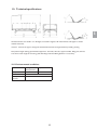
1
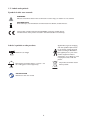
Invacare®OctaveTM
User Manual (EN)
Table of Contents
1. General Information . . . . . . . . . . . . . . . . . . . . . . . . . . . . . . . . . . . . . . 3
2. Operating the OctaveTM . . . . . . . . . . . . . . . . . . . . . . . . . . . . . . . . . . . . 7
3. Receiving the OctaveTM . . . . . . . . . . . . . . . . . . . . . . . . . . . . . . . . . . . . 11
4. Disassembly of parts. . . . . . . . . . . . . . . . . . . . . . . . . . . . . . . . . . . . . . 14
5. Wiring . . . . . . . . . . . . . . . . . . . . . . . . . . . . . . . . . . . . . . . . . . . . . . . . . 15
6. Part numbers for accessories . . . . . . . . . . . . . . . . . . . . . . . . . . . . . . 16
7. Cleaning and Maintenance. . . . . . . . . . . . . . . . . . . . . . . . . . . . . . . . . 17
8. Trouble-shooting the electrical system . . . . . . . . . . . . . . . . . . . . . . 20
9. Electrical data . . . . . . . . . . . . . . . . . . . . . . . . . . . . . . . . . . . . . . . . . . . 21
10. Technical specifications . . . . . . . . . . . . . . . . . . . . . . . . . . . . . . . . . . 25
11. Weight . . . . . . . . . . . . . . . . . . . . . . . . . . . . . . . . . . . . . . . . . . . . . . . . 27
12. Disposal . . . . . . . . . . . . . . . . . . . . . . . . . . . . . . . . . . . . . . . . . . . . . . . 27
2
1. General information
This manual must be given to the user of the product. Before using this product, read this manual and save for
future reference.
Please note that there may be sections in this User Manual, which are not relevant for your bed.
All indications of right and left are based on a patient lying on his back in the bed.
Metal side rails and U-profile bed ends may be disassembled without the use of any tools.
The bed is designed for use especially for home care.
The bed is designed for patients over the age of 12 years. 150 cm and longer.
The bed is a nursing bed with modular structure.
Max patient weight: 350 kg (provided the equipment - bed ends, side rails, support handles, lifting pole and
mattress have a total weight of max 35 kg).
Safe Working Load: Max 385 kg (Patient + accessories).
The Ocatve™ bed is defined to be used according to;
Application environment 3; Long-term care in a medical area where medical supervision is required and
monitoring is provided if necessary and medical electrical equipment used in medical procedures may be provided to help maintain or improve the condition of the patient.
Application environment 4; Care provided in a domestic area where medical electrical equipment is used to
alleviate or compensate for an injury, disability or disease.
In order to optimise the patient’s comfort Invacare® recommends using a 15 cm mattress.
(see order numbers in section 6 "Part numbers for accessories").
1.2 Certification
OctaveTM is marked in accordance with directive 93/42/EEC concerning Medical
Devices.
OctaveTM is tested and approved in accordance with EN 60601-2-52 of TÜV
Product Service in Germany.
OctaveTM has undergone a risk analysis according to EN 14971.
The motors and control unit of the bed are approved according to IEC 60601-1:2005 3:rd edition.
The hand control, control unit and motors are protected according to IPX6 or IPX4.
A lock cam must be used on the control unit - if not, Invacare®can not guarantee the IP protection.
All service work described in chapter 7 may only be performed by personnel who have been trained or instructed
by Invacare® service course.
If the functions of the bed change, please send the bed for a check-up according to the maintenance chart in
chapter 7.
Invacare® is certified according to EN ISO 9001 and ISO 13485 and ensures compliance by 3:rd party.
Throughout the entire production process our materials/products are quality controlled by the operators.
Additionally, a final test is carried out prior to packaging and shipping.
The operator carrying out the final test, which includes a check of all moveable
parts, motors and castors, issues a QA number on the product thereby confirming
its quality.
QA XXX
If the product does not correspond to the quality demands of Invacare®, it will be discarded.
If, contrary to our expectations, a problem should arise in connection with the delivered product, please contact
your Invacare® supplier. An address list is shown on the back of this manual.
3
EN
1.1 Intended use
1.3 Labels and symbols
Symbols in this user manual:
WARNING
Indicates a hazardous situation that could result in serious injury or death if it is not avoided.
INFORMATION
Gives useful tips, recommendations and information for efficient, trouble-free use.
This product complies with Directive 93/42/EEC concerning medical devices.
The launch date of this product is stated in the CE Declaration of conformity.
Labels / symbols on the product:
Applied Part, Type B, complying
with the specified requirements
for protection against electrical
shock according to IEC60601-1.
(An applied part is a part of the
medical equipment which is
designed to, or are likely to, come
into physical contact with the
patient.
Maximum user weight
Safe working load (SWL) (Patient + mattress + side
rails + lifting pole + other equipment).
INSTRUCTION
Reference to the user manual.
4
The product should be reused
where possible
To identify the product please look at the product label:
Electrical information
Iin
Vin
Int.
AC
Max
min
kg
A
Date of production.
Current in
Voltage in
Intermitens
Alternating current
Maximum
minutes
kilogram
Ampere
Symbols
IPX4 or IPX6 depending on configuration.
1.4 Description of the main parts in the mattress support:
Leg section
Back rest
Thigh section
Seat section
5
EN
Type no. of the bed.
Serial no.
1.5 Safety and warnings
The bed fulfils all requirements regarding maximum distances.
However, if the bed is used for the care of patients with a small body dimensions, it must be especially noted that there is a risk of such a patient slipping through the openings between the side rails
or through the opening between the side rail and the mattress support.
The bed must not be used by patients under 12 years of age, or by patients with body size equivalent to an average 12-year-old or smaller.
The bed, in combination with side rails, must not be used for persons under 45 kg or under 150
cm´s height, or for persons that are restless (spasms) or confused, unless a professional risk assessment has taken place and been accepted, or a correctly installed safety cover on the side rails are
used.
The bed must be placed so that the height adjustment (up(down) is not obstructed by, for example,
lifts or furniture.
Electromagnetic interference between the bed and other electrical products can occur. To reduce
or eliminate such electromagnetic interference, increase the distance between the bed and the
products or switch them off.
This medical bed can be used together with medical electrical equipment connected to the heart
(intracardially) or the blood vessels (intravascularly), provided that following are respected:
The medical bed should be equipped with means for potential equalization connection (See the
symbol in chapter ”Electrical data”).
The medical electrical equipment should not be fixed on the bed’s metallic accessories such as
side rails, lifting pole, drip rod, bed ends ect.
In addition, the medical electrical equipment power supply cord should be kept clear of the accessories or any other moving part of the bed.
Invacare® accepts no liability for any use, change or assembly of the product other than as stated in
any use,
change
or assembly
of the
this User Manual.Invacare®
If the bedaccepts
showsno
anyliability
signs offordamage
upon
delivery,
please see
theproduct
terms of deother
as stated
this
user manual.
livery. Accessories
notthan
mentioned
in in
this
manual
must not be used.
When using side rails and the according safety cover, it is essential to ensure correct fitting otherwise there is danger of entrapment / suffocation between mattress support, side
rail and bed end!
Do not place anyInvacare®
objects underneath
accepts no bed.
liability for any use, change or assembly of the product
other than as stated in this user manual.
If the functions of the bed change, send the bed immediately for a check-up according to the maintenance chart..
6
1.6 Warranty
The warranty covers all material and production defects for 2 years from the date of delivery, provided it can be
demonstrated that such defects were present before delivery. All manufacturing faults or defects must be promptly
reported Invacare® may repair the fault or replace the component. The warranty provided by Invacare® does not
cover additional costs (transport, packaging, labour, sundry expenses, etc. are for the customer’s account).
Damage caused during transport that is not directly reported to the forwarder at the moment of delivery.
Repairs performed by unauthorized centers and personnel.
Parts subject to normal wear.
Malicious damage or damaged caused by improper use of the bed.
1.7 Service life
The expected service life of this product is seven years when used daily and in accordance with the safety
instructions, maintenance intervals and correct use, stated in this manual. The effective service life can vary
according to frequency and intensity of use.
2. Operating the OctaveTM
Disconnect the plug from the mains before moving the bed. The cable must be kept clear of the
floor and the castors during transport. Make sure that the mains cable cannot be jammed or in any
other way damaged when the bed is used.
Always leave the bed in the lowest position. Otherwise there is a risk of entrapment due to
accidental lowering of the mattress support. A person can be seriously injured under the bed
during height adjustment.
There is a risk of entrapment of fingers on assembly and operation of the metal side rail.
The bed’s castors must be locked whilst nursing a patient in bed or when using any positioning
function. The bed must be locked when the patient moving in and out of the bed.
The bed’s electrical equipment must not be dismantled or combined with other electrical equipment.
7
EN
The warranty does not cover:
2.1 Operating the Invacare® OctaveTM with the hand control
To operate the mattress support, the bed is equipped with one of the following types of hand controls:
HB 80 or
HL 80 with integrated ACP function (key)
UP / DOWN
Sitting position
Backrest
Leg section
Thigh section
Height adjustment of the
bed
Key for locking and unlocking the
electrical functions
Insert the key below each button to
respectively lock and unlock the hand
control functions
There is a risk of entrapment whilst operating the bed.
When entering or exiting the bed, the height adjustment should be used. Furthermore, the backrest can be used as support (yellow button on the hand control). However, the thigh- and leg section must be horizontal, otherwise, there is risk of overloading of the mattress support.
8
2.2 Using the central brake
EN
Braking the bed: If the brake is in neutral, step on the red pedal.
Releasing the brake: Step on the green pedal, until the brake is in
the neutral position.
The bed’s castors must be locked whilst nursing a patient in bed or when using any positioning
function. The bed must be locked when the patient moving in and out of the bed.
The bed must not be transported when occupied.
The castors might under special conditions be difficult to manoeuvre due to the floor covering being untreated
or in poor condition. In matters of doubt, Invacare® recommends the placement of a suitable type of protection
between the castors and the floor.
2.3 Operation of the BRITT V wooden side rail/Line Alu
UP: Pull up the top wooden bar, until the
locking pin locks with an audible click.
DOWN: Lift the top wooden bar and press
the two locking pins together. Lower the side rail.
Locking pins
There is a risk of entrapment on assembly and operation of the side rails.
Britt V wooden side rails//Line Alu conforms to the European standard EN60601-2-52. For those
however,with a small body size, there will be a risk of entrapment.
9
2.4 Adjusting the height of the lifting pole
Loosen the cord as shown in fig. A. The lifting handle can now be adjusted to the desired height. Press the cord
together as shown in fig. B and check that the cord is locked in the cord lock by pulling the handle as shown in
figure C.
B
A
C
2.5 Emergency release of the mattress support parts
An emergency release of the mattress support is necessary in the case
of e.g. a power or motor failure.
An emergency release of the height adjustment is NOT possible!
Remove the plug from the mains before the emergency
release of the mattress support.
In an emergency case the mattress sections are released
by pulling out the cotter pin from the motor in question.
A minimum of 2 people are required to release a mattress section. Both people should hold the
mattress section in locked position. One person pulls out the cotter pin.
Both slowly lower the mattress section until it is completely down.
If the mattres support is removed, the mattress will not follow the beds movements when adjusting
the head/leg sections. It is also possible that the mattress slips sideways which could cause the user
to fall to the ground or get trapped in the bed.
10
3. Receiving Invacare® OctaveTM
Due to condensation, the bed may not be used until it has reached room temperature (10-50o C).
After each assembly, check that all fittings are properly tightened and that all parts have the correct
function.
The bed’s - mattress support and base frame - will be delivered assembled on a trolley.
By ordering a standard bed the following parts will be delivered:
x
Assembled bed on trolley.
x
Fitting (2 pcs.) incl. mounting screws (8 pcs.).
x
Wooden-bed ends (2 pcs.).
The following can be delivered an option: (see chapter 8 for order no.).
x
BRITT wooden side rails/Line Alu (a pair), only for L=200 cm (standard in the UK).
x
Wooden bar (4 pcs.) incl. mounting screws (8 pcs.).
x
Support handle.
x
Lifting pole incl. mounting screws (2 pcs.).
x
Mattress support extension 10 cm. Can be used in head- and bed end.
3.1 Parts of a standard bed
1.
2.
3.
4.
5.
6.
7.
8.
9.
10.
11.
12.
13.
Base with central braking system.
Inner shear arm.
Outer shear arm.
Motor, hi/low.
Motor for back rest.
Motor - thigh section (with control
unit).
Motor - leg section
Top frame incl. seat section.
Back rest.
Thigh section
Leg section
Fitting
Wooden - bed ends.
11
EN
Check whether the bed shows any signs of damage. If the bed is damaged, see terms of delivery.
3.2 Mounting the Invacare® OctaveTM
Receiving the bed on the trolley: (2 persons required)
a)
Apply all 4 braked castors on the trolley.
b) Apply all 4 braked castors on the bed.
c)
Remove the delivered equipment from the trolley.
d) Lower the bed and the trolley, into horizontal
position standing on the bed castors.
e) Dismount the trolley from the bed.
When lowering the bed into horizontal position, 2 persons are required.
Connect Invacare® OctaveTM to the mains.
The connection to the socket outlet must always be accessible in case an electric error should
occur
For ergonomic working position:
Raise the bed (hi/low) to approx. 60 cm above floor level.
(See section 2 “Operation of the Invacare® OctaveTM”).
1. Assembling the fittings
a)
Push bed end through the pipes on the top frame.
(Visible insert pipe is about 4.5 cm).
b) Tighten the bed end with enclosed screws.
2. Mounting the wooden bed end
a)
Slide the wooden bed end into the U-profile.
3.3 Mounting wooden adapters and wooden side rail (accessories)
Mounting wooden trim
a)
Remove the exposure on the bed end.
b) Mount the wooden trim with the enclosed mounting screws.
c)
Make sure that all 4 wooden trims have been correctly
mounted/tightened.
12
3.4 Mounting the Britt wooden side rail/Line Alu (accessories)
1.
2.
3.
4.
5.
Raise the bed about one third.
Mount one end at a time. Lift the upper bar and guide the slide bracket to the bed end rail (A).
Press the locking pin of the side rail with a finger (B).
Guide the side rail to the upper position. There will be an audible click when it locks.
Mount the end stop brackets (C).
B
C
EN
A
3.5 Mounting support handle (accessories)
a)
Mount the support handles on the tube of either the back or
leg sections.
Note! Do not mount the support handle on the seat or thigh section.
b) Tighten the finger screws.
Note! The distance between 2 support handles or support handle and bed end must be more than 32 cm.
Placing support handles in wrong positions can cause serious damage or suffocation,
if body parts are trapped between support handles or between a support handle and bed end.
3.6 Mounting the lifting pole (accessories)
a)
Push the lifting pole bottom piece in the fitting under the back rest.
b) Mount the enclosed screws and nuts and tighten them.
13
3.7 Mounting the mattress support extension (10 cm)
Note! It is not possible to use the wooden side rail in combination with the mattress support extension.
Therefore dismount the wooden side rails first.
The mattress support extension can be mounted in either the head- or foot end
or in both ends.
a)
Loosen screws from the bed end.
b) Remove the bed end.
c)
Remove the ferrules in the tube ends for the mattress support
and mount the extension.
d) Tighten up with the enclosed screws.
e) Mount the bed end in the outer position (4 screws per fitting).
(Visible insert pipe is about 14.5 cm).
4. Disassembly of parts
4.1 Dismounting mattress support - from the base
The mattress support can be disassembled from the base. To disassemble the mattress support from the base
relevant tools and 2 persons are required.
a)
Dismount all accessories incl. bed end.
b) Lower the bed into the lowest position.
c)
Dismount the height adjustment motor cable from the control unit.
d) Raise the back section to the highest position.
e) Loosen and remove the screws/nuts between mattress support
and shear arms.
f)
Lift the mattress support free from the guideway.
g)
Lower the back section to the lowest position.
h) Remove the power plug from the bed and lift the mattress support
off the shear arm.
4.2 Dismounting the BRITT V/Line Alu side rail
a)
Raise the bed about one third.
b) Place the side rail in the highest position.
c)
Dismount the end stop brackets. (4 pcs.).
d) Lower the side rail, (see section "Operation of the BRITT wooden/Line Alu side rail") until it is completely
below the bed end rail.
14
EN
5. Wiring
Check the cabling by operating the motors of the bed to their outer positions. When all wires have been correctly
installed, there is no squeezing risk of the cables.
It is normal for cables to loosen slightly after short usage.
The cables are equipped with plugs at both sections, hence, they can be replaced independently
(except for the height motor).
The cables are attached to the top frame with cable clips.
The hand control, control unit and motors are protected according to IPX4 or IPX6.
It can be dangerous to roll over the mains cable.
Do not bring mains cable into moving parts.
Disconnect the plug from the mains before moving the bed.
The cables must be mounted in such a way that they are kept clear of the floor and do not
block the castors.
A lock cam must be used on the control unit - if not, Invacare®cannot guarantee the IP
protection.
15
6. Part numbers for accessories
Article
Dimensions
Order no.
Line side rail (beech, complete) . . . . . . . . . . . . . . . . . . . . . . . . . . . . . . . . . . . . . . . . . . . . . . . . . . . . . . . 1522786-0125
Line side rail, extendable (beech, complete) . . . . . . . . . . . . . . . . . . . . . . . . . . . . . . . . . . . . . . . . . . . . . 1522787-0125
BRITT V wooden siderail, 2 pcs . . . . . . . . . . . . . . . . . . . . . . . . . . . . . . . . . . . . . . . . . . . . . . . . . . . . . 1538458-XXXX
Wooden trim for Line and Britt V side rail) . . . . . . . . . . . . . . . . . . . . . . . . . . . . . . . . . . . . . . . . . . . . . 1544208-0101
Side rail height extender for Line, extendable, beech, 1 piece . . . . . . . . . . . . . . . . . . . . . . . . . . . . . . 1538345-0125
Side rail height extender for Britt IV and V. 1 piece . . . . . . . . . . . . . . . . . . . . . . . . . . . . . . . . . . . . . 1538420-0125
Support handle (1 psc.) . . . . . . . . . . . . . . . . . . . . . . . . . . . . . . . . . . . . . . . . . . . . . . . . . . . . . . . . . . . . . . 1446353-0152
Lifting pole. . . . . . . . . . . . . . . . . . . . . . . . . . . . . . . . . . . . . . . . . . . . . . . . . . . . . . . . . . . . . . . . . . . . . . . . . 50.57700.M0
Mattress support extension 10 cm . . . . . . . . . . . . . . . . . . . . . . . . . . . . . . . . . . . . . . . . . . . . . . . . . . . . 1446498-0152
Mattress max. load 200 kg . . . . . . . . . . . . . . . . . . . . . . . . . . . . . 116x205x15 . . . . . . . . . . . . . . . . . . . . . . . 1484429
Mattress max. load 350 kg . . . . . . . . . . . . . . . . . . . . . . . . . . . . . 116x205x15 . . . . . . . . . . . . . . . . . . . . . . . 1451259
Mattress max. load 200 kg (extension) . . . . . . . . . . . . . . . . . . . 116x10x15 . . . . . . . . . . . . . . . . . . . . . . . . 1484640
Mattress max. load 350 kg (extension) . . . . . . . . . . . . . . . . . . . 116x10x15 . . . . . . . . . . . . . . . . . . . . . . . . 1451260
Cover for side rail height extender, padded (covering both the normal side rail
and the height extender), 1 piece. . . . . . . . . . . . . . . . . . . . . . . . . . . . . . . . . . . . . . . . . . . . . . . . . . . . . . . . . . 1558095
Cover for Line and Britt V side rail, padded, piece . . . . . . . . . . . . . . . . . . . . . . . . . . . . . . . . . . . . . . . . . . . . 1449588
Cover for Line and Britt V side rail, extra padded, piece . . . . . . . . . . . . . . . . . . . . . . . . . . . . . . . . . . . . . . 1449589
Cover for Line extended side rail, + 10 cm, padded, piece . . . . . . . . . . . . . . . . . . . . . . . . . . . . . . . . . . . . . 1449591
Cover for Line extended side rail, + 20 cm, padded, piece . . . . . . . . . . . . . . . . . . . . . . . . . . . . . . . . . . . . . 1449592
Cover for Line and Britt V side rail, net piece . . . . . . . . . . . . . . . . . . . . . . . . . . . . . . . . . . . . . . . . . . . . . . . . 1449590
Cover for Line extended side rail, + 10 cm, net, piece . . . . . . . . . . . . . . . . . . . . . . . . . . . . . . . . . . . . . . . . 1449593
Cover for Line extended side rail, + 20 cm, net, piece . . . . . . . . . . . . . . . . . . . . . . . . . . . . . . . . . . . . . . . . 1449594
Scala Basic 2 and Basic plus 2
3/4 length collapsible steel side rail (168 cm x 40 cm), mounted on the side tube. Release button in the head section.
Scala Medium 2
3/4 length collapsible steel side rail (165 cm x 46 cm), mounted on the side tube. Release button in the head section.
Scala Decubi 2
3/4 length collapsible steel side rail (168 cm x 54 cm), mounted on the side tube. Release button in the head section.
Line Standard
Full length side rail (206 cm x 40 cm) in aluminum or wood finish, mounted on the bed end rail. Two centered
release buttons for folding of the gate.
Line Extendable
Full length side rail with telescopic extension (206-226 cm x 40 cm) in aluminum or wood finish, mounted on the
bed end rail. Two centered release buttons for folding of the gate.
Britt V
Full length side rail (205 cm x 40 cm) in wood, mounted on the bed end rail. Two centered release buttons for
folding of the gate.
Verso ll
3/4 length collapsible steel side rail (156 cm x 40 cm), mounted on the side tube. Release button in the foot section.
16
7. Cleaning and maintenance
Only personnel who have received the necessary instructions or training may perform service and maintenance of the bed.
With normal daily use, service must be carried out according to the service schedule after 2 years use and
thereafter every second year.
For beds with electrical equipment a safety test comprising control of the motors’ performance and
mechanical state is recommended once a year.
When reconditioning the bed, service must be carried out according to the service schedule.
7.1 Cleaning
The bed does not tolerate cleaning in automatic washing plants or the use of water-jet based cleaning equipment.
1.
2.
3.
4.
5.
Please make sure the power plug is removed from the wall socket outlet before cleaning.
The bed should be washed down using a wet sponge, cloth or brush.
Use ordinary household cleaning agents. Never use acids, alkalines or solvents such as acetone or cellulose
thinner.
The backrest and the leg/thigh sections can be lifted from the mattress support, which facilitates cleaning and
access to the control unit.
The hand control, motors and control unit may be washed with brush and water.
Important details for cleaning IPX6 and IPX4 hand controls, control unit and motors:
Water may be pressurised, but never use high-pressure cleaning or steam cleaning directly on the electrical
parts.
6.
Dry the bed after cleaning.
Make sure that all electric plugs are in place during washing.
17
EN
The base frame must be supported during service inspections to prevent accidental lowering
7.2 Maintenance
A service contract can be made in the countries, where Invacare® has its own sales company. In certain countries
Invacare® offers courses in service and maintenance of the OctaveTM. Spare parts lists and additional user manuals
are available from the Invacare® homepage.
Before use
Ensure that all manual and electrical parts functions correctly and are in a secure state.
Check, by raising and lowering the bed, that the shear arms run smoothly in the guideways.
- After 3 months
Ensure that all manual and electrical parts are functioning, and tighten bolts, screws, nuts, etc.
- Every year
We recommend a safety test comprising the motors’ performance and mechanical state.
Motors, hand control and control unit:
These parts are serviced by exchanging the faulty part.
- Every second year
Service should be performed after the maintenance chart. See chapter 7.4 - Maintenance chart.
When reconditioning the bed, service must be carried out according to the service schedule.
7.3 Lubrication plan
We recommend to lubricate the Invacare® OctaveTM according to the following instructions:
1.
2.
3.
4.
Guideways
Swivel on shear arms
Swivel on mattress support -accessories
Swivel on motor
- lubricate with grease
- lubricate with oil
- lubricate with oil
- lubricate with oil
Lubricate with medically clean oil, e.g. KEW-WO 50, order no.: 813239 and grease, order no: 1497607.
18
7.4 Maintenance chart
Service and maintenance of the Invacare® OctaveTM must only be performed by personnel who have
received the necessary instruction or training.
S/N (located on the mattress support): ___________________
Date:
Initials.:
EN
Circlips and cotter pins checked.
Screws tightened.
Weldings checked.
Side rail locking and moving system tested.
Castor fittings tightened.
Castor brakes checked.
Height adjustment motor checked.
Back rest motor checked.
Thigh section motor checked.
Leg section motor checked.
Wiring correct and undamaged. Plugs undamaged.
Damaged paintwork repaired.
Lubrication according to the lubrication plan
(chapter 12).
The wooden side rails´ gliding system must not be
lubricated with oil - otherwise the wooden bars will
move sluggishly.
Accessories checked.
Measurements can be done at internal threads after removal of finger screws.
7.5 Motors, control unit and hand control
These parts are not serviceable, they must be replaced.
A safety test comprising control of the motors’ performance and mechanical state is recom
mended once a year.
Motors, control unit and hand control must be regularly cleaned from dust and dirt and they must be inspected for
mechanical damage or breakage.
Inspect anchor points, cables, piston rod, casing and plugs and check the correct functioning of the motors.
19
8. Trouble-shooting the electrical system
Note! Make sure that the mains are connected.
Symptom
Possible cause
Remedy
1) Mains not connected.
2) Fuse in the control unit is blown.
3) Control unit defective.
1) Connect mains.
2) Replace the control unit.
3) Replace the control unit.
1) Motor plug not pushed fully into the
control unit.
2) Motor is defective.
3) Motor cable is damaged.
4) Control unit defective.
1) Insert the motor plug
properly into the control
unit.
2) Replace the motor.
3) Replace the motor.
4) Replace the control unit.
Mains indicator lights up, but the
motor is not running.
No relay sound is heard from the
control unit.
1) Hand control defective.
2) Control unit defective.
1) Replace the hand control.
2) Replace the control unit.
Control unit is in order except
one direction on one channel.
1) Hand control defective.
2) Control unit defective.
1) Replace the hand control.
2) Replace the control unit.
Motor damaged.
Replace the motor.
Mains indicator does not light up.
Mains indicator lights up, but the
motor is not running.
The relays in the control unit
makes a clicking noise.
Motor is running, but the piston
rod does not move.
The motor cannot lift full load.
Motor noise, but no movement of
piston rod.
Piston rod operates inwards but
not outwards.
Motor plug not
connected
Relay sound
Defective motor
No motor sound
Defective control
unit
Motor does not
run
No relay sound
Defective hand
control
Piston rod does
not move
Motor sound
20
Defective motor
9. Electrical data
Voltage supply:
Max. current input:
Intermittent (Duty cycle of motors):
Degree of protection:
Sound level:
230 Voltage AC/50 Hz.
3 A.
Int.10% 2 min/18 min.
IPX6 * or IPX4 **
48 dB (A)
Double insulated, class II
EN
Alternating current:
Applied Part, Type B, complying with the specified requirements
for protection against electrical shock according to IEC60601-1.
(An applied part is a part of the medical equipment which is
designed to, or are likely to, come into physical contact
with the patient.
Potential equalization.
The control unit has no contact breaker, hence, disconnecting the mains plug is the only means of disconnecting the
power supply.
* The IPX6 classification means that the electrical system is protected against water projected in powerful jets
from any direction
** The IPX4 classification means that the electrical system is protected against water splashed against the component from any direction.
The hand controls have different IP-classes (see label on back), the IP-classification of the hand control decides the
overall classification of the bed.
21
9.1 Guidance and manufacturer's declaration - electromagnetic emission
Guidance and manufacturer´s declaration – electromagnetic emission
The Octave Bed is intended for use in the electromagnetic environment specified below. The customer or
the user of the Octave Bed should assure that it is used in such an environment.
Emissions test
RF emissions
Compliance
Electromagnetic environment - guidance
Group 1
CISPR 11
RF emissions
Class B
CISPR 11
Harmonic emissions
Class A
IEC 61000-3-2
Voltage fluctuations
/
flicker emissions
The Octave Bed uses RF energy only for its internal function.
Therefore, its RF emissions are very low and are not likely to
cause any interference in nearby electronic equipment. The
Octave Bed is suitable for use in all establishments, including
domestic establishments and those directly connected to the
public low-voltage power supply network that supplies
buildings used for domestic purposes.
Complies
IEC 61000-3-3
Guidance and manufacturer´s declaration – electromagnetic immunity
The Octave Bed is intended for use in the electromagnetic environment specified below. The customer or the
user of the Octave Bed should assure that it is used in such an environment.
Immunity test
Electrostatic
discharge (ESD)
IEC 61000-4-2
Electrostatic
transient / burst
IEC 61000-4-4
Surge
IEC 61000-4-5
Voltage dips,
short
interruptions and
voltage variations
on power supply
input lines
IEC 61000-4-11
Power frequency
(50/60 Hz)
magnetic field
IEC 60601
test level
Compliance level
± 6 kV contact
± 6 kV contact
± 8 kV air
± 8 kV air
± 2 kV for power
supply lines
± 2 kV for power
supply lines
± 1 kV for input/output
lines
± 1 kV differential
mode
± 1 kV for input/output
lines
± 1 kV differential
mode
± 2 kV common mode
< 5 % UT
(>95 % dip in UT )
for 0,5 cycle
± 2 kV common mode
< 5 % UT
(>95 % dip in UT )
for 0,5 cycle
40 % UT
(60 % dip in UT )
for 5 cycles
40 % UT
(60 % dip in UT )
for 5 cycles
70 % UT
(30 % dip in UT )
for 25 cycles
70 % UT
(30 % dip in UT )
for 25 cycles
< 5 % UT
(>95 % dip in UT )
for 5 sec
< 5 % UT
(>95 % dip in UT )
for 5 sec
3 A/m
Floors should be wood, concrete or
ceramic tile. If floors are covered
with synthetic material, the relative
humidity should be at least 30 %.
Mains power quality should be that
of a typical commercial or hospital
environment.
Mains power quality should be that
of a typical commercial or hospital
environment.
Mains power quality should be that
of a typical commercial or hospital
environment. If the user of the
Octave Bed requires continued
operation during power mains
interruptions, it is recommended that
the Octave Bed be powered from an
uninterruptible power supply or a
battery.
Power frequency magnetic fields
should be at levels characteristic of
a typical location in a typical
commercial or hospital environment.
3 A/m
IEC 61000-4-8
NOTE
Electromagnetic environment guidance
UT is the a. c. mains voltage prior to application of the test level.
22
Recommended separation distances between
portable and mobile RF communications equipment and the Octave Bed
The Octave Bed is intended for use in an electromagnetic environment in which radiated RF disturbances are
controlled. The customer or the user of the Octave Bed can help prevent electromagnetic interference by
maintaining a minimum distance between portable and mobile RF communications equipment (transmitters)
and the Octave Bed as recommended below, according to the maximum output power of the communications
equipment
Separation distance according to frequency of transmitter
m
150 kHz to 80 MHz
d
[
80 MHz to 800 MHz
3,5
] P
V1
d
[
800 MHz to 2,5 GHz
3,5
] P
E1
d
[
7
] P
E1
W
0,01
0,12
0,12
0,23
0,1
0,37
0,37
0,74
1
1,17
1,17
2,33
10
3,69
3,69
7,38
100
11,67
11,67
23,33
For transmitters rated at a maximum output power not listed above the recommended separation distance
d in metres (m) can be estimated using the equation applicable to the frequency of the transmitter, where P
is the maximum output power rating of the transmitter in watts (W) according to the transmitter
manufacturer.
NOTE 1 At 80 MHz and 800 MHz, the separation distance for the higher frequency range applies.
NOTE 2 These guidelines may not apply in all situations. Electromagnetic propagation is affected by
absorption and reflection from structures, objects and people.
23
EN
Rated maximum
output of
transmitter
Recommended separation distances between
portable and mobile RF communications equipment and the Octave Bed
The Octave Bed is intended for use in an electromagnetic environment in which radiated RF disturbances are
controlled. The customer or the user of the Octave Bed can help prevent electromagnetic interference by
maintaining a minimum distance between portable and mobile RF communications equipment (transmitters)
and the Octave Bed as recommended below, according to the maximum output power of the communications
equipment
Separation distance according to frequency of transmitter
m
Rated maximum
output of
transmitter
150 kHz to 80 MHz
d
[
80 MHz to 800 MHz
3,5
] P
V1
d
[
800 MHz to 2,5 GHz
3,5
] P
E1
d
[
7
] P
E1
W
0,01
0,12
0,12
0,23
0,1
0,37
0,37
0,74
1
1,17
1,17
2,33
10
3,69
3,69
7,38
100
11,67
11,67
23,33
For transmitters rated at a maximum output power not listed above the recommended separation distance
d in metres (m) can be estimated using the equation applicable to the frequency of the transmitter, where P
is the maximum output power rating of the transmitter in watts (W) according to the transmitter
manufacturer.
NOTE 1 At 80 MHz and 800 MHz, the separation distance for the higher frequency range applies.
NOTE 2 These guidelines may not apply in all situations. Electromagnetic propagation is affected by
absorption and reflection from structures, objects and people.
24
EN
10. Technical specifications
All measurements are stated in cm. All angles are stated in degrees. All measurements and angles are stated
without tolerances.
Invacare® reserves the right to change the stated measurements and angles without preceding warning.
Max patient weight: 350 kg (provided the equipment - bed ends, side rails, support handles, lifting pole and mattress have a total weight of max 35 kg). Safe Working Load: Max 385 kg (Patient + accessories).
10.1 Environmental conditions
Temperature
Relative humidity
Atmospheric
pressure
Storage and
Operation
Transportation
-10°C — +50°C
+5°C — +40°C
10% — 80% RH
800 hPa — 1100 hPa
25
10.1
Mattress dimensions
Safety aspects regarding combination of side rails and mattresses:
– In order to obtain the highest possible safety level, when using the bed in combination with side
rails, it is important to respect the minimum and maximum measures for mattresses stated in the
table.
– To prevent the possibility of the user crawling over the top of the side rail (with the risk of severe
injury due to e.g. falling) a minimum vertical distance of 22 cm between the top of the mattress
and the top of the side rail is to be respected. The maximum mattress height in combination with a
given side rail is stated in the table.
– To prevent head entrapment between the inside surface of the side rail and the mattress (with
the risk of e.g. suffocation) a safety maximum space has to be respected. It is especially important to
focus on this risk, when using very thick or soft mattresses (low density) or a combination of both.
The minimum width (and length) of mattresses in combination with a given side rail is stated in the
table.
Max Height
Mattress
Line/ Line extendable side rail 21 cm
Britt V side rail
21 cm
Min. Height
Mattress
15 cm
15 cm
Density:
Dacapo heavy user Max 350 kg
5 cm Visco-elastic foam 50 kg/m3
5 cm Cold foam 50 kg/ m3
5 cm Cold foam 50 kg/m3
Dacapo heavy user Max 250 kg
5 cm Visco-elastic foam 50 kg/m3
5 cm Cold foam 38 kg/ m3
5 cm Cold foam 50 kg/m3
26
Min. Width
Mattress
116-120 cm
116-200 cm
Min. Length
Mattress
200 cm
200 cm
11. Weight
Mattress support. . . . . . . . . . . . . . . . . . . . . . . . . 72,0 kg
Base incl. shear arm . . . . . . . . . . . . . . . . . . . . . . 71,0 kg
Bed end fitting . . . . . . . . . . . . . . . . . . . . . . . . . . . . 5,0 kg/pcs.
Wooden bed end . . . . . . . . . . . . . . . . . . . . . . . . . 8,5 kg/pcs.
Wooden trims 2 pcs. . . . . . . . . . . . . . . . . . . . . . . 2,0 kg
Wooden side rail (BRITT V) . . . . . . . . . . . . . . . . 7,5 kg/pcs.
Lifting pole. . . . . . . . . . . . . . . . . . . . . . . . . . . . . . 10,0 kg
Support handle . . . . . . . . . . . . . . . . . . . . . . . . . . . 2,0 kg
Mattress approx. . . . . . . . . . . . . . . . . . . . . . . . . . . 8,0 kg
12. Disposal
This product has been supplied from an environmentally aware manufacturer that complies
with the Waste Electrical and Electronic Equipment (WEEE) Directive 2002/96/CE.
This product may contain substances that could be harmful to the environment if disposed of in
places (land fills) that are not appropriate according to legislation.
The »crossed out wheelie bin« symbol is placed on this product to encourage you to recycle wherever possible.
Please be environmentally responsible and recycle this product through your recycling facility at its end of life.
27
EN
Complete bed, excluding accessories . . . . . . . 170,0 kg
Customer Sales and Service
Sweden & Finland
Netherlands
Spain
INVACARE AB
Fagerstagatan 9 / Box 66
SE-163 91 Spånga
Phone: +46 8 761 70 90
Fax: +46 8 761 81 08
www.invacare.se
[email protected]
[email protected]
INVACARE B.V.
Celsiusstraat 46
NL-6716 BZ Ede
Phone: +31 318 69 57 57
Fax: +31 318 69 57 58
www.invacare.nl
[email protected]
[email protected]
INVACARE S.A.
Ireland
United Kingdom
Norway & Iceland
INVACARE Ireland Ltd
Unit 5 Seatown Business Campus
Seatown Road, Swords,
IE-County Dublin
Phone: +353 1 810 70 84
Fax: +353 1 810 70 85
www.invacare.co.uk
[email protected]/
[email protected]
INVACARE Ltd
Pencoed Technology Park,
Pencoed
GB-Bridgend, CF35 5AQ
Phone: +44 1 656 77 62 00
Fax: +44 1 656 77 62 01
www.invacare.co.uk
[email protected]/
[email protected]
INVACARE AS
Grensesvingen 9
Postbox 6230, Etterstad
NO-0603 Oslo
Phone: +47 22 57 95 00
Fax: +47 22 57 95 01
www.invacare.no
[email protected]
[email protected]
Denmark
France
Belgium & Luxemburg
INVACARE A/S
Sdr. Ringvej 37
DK-2605 Brøndby
Phone: +45 36 90 00 00
Fax: +45 36 90 00 01
www.invacare.dk
[email protected]
INVACARE Poirier SAS
Route de St. Roch
FR-37230 Fondettes
Phone: +33 2 47 62 64 66
Fax: +33 2 47 42 12 24
www.invacare.fr
[email protected]
INVACARE N.V.
Autobaan 22
BE-8210 Loppem, Brügge
Phone: +32 50 83 10 10
Fax: +32 50 83 10 11
www.invacare.be
[email protected]
Switzerland
Germany
Portugal
INVACARE AG
Benkenstrasse 260
CH-4108 Witterswil
Phone: +41 61 487 70 80
Fax: +41 61 487 70 81
www.invacare.ch
[email protected]
INVACARE GmbH
Alemannenstrasse 10
DE-88316 Isny
Phone: +49 75 627 000
Fax: +49 75 627 00 66
www.invacare.de
[email protected]
INVACARE Lda
Rua Estrada Velha 949
PT-4465-784 Leça do Balio
Phone: +351 225 10 59 46/47
Fax: +351 225 10 57 39
www.invacare.pt
[email protected]
Italy
New Zealand
Australia
INVACARE MECC SAN s.r.l.
Via dei Pini 62
IT-36016 Thiene (VI)
Phone: +39 0445 38 00 59
Fax: +39 0445 38 00 34
www.invacare.it
[email protected]
INVACARE NZ
4 Westfield Place,
Mt. Wellington
NZ-Auckland
Phone: +64 9 917 39 39
Fax: +64 9 917 39 57
www.invacare.co.nz
[email protected]
INVACARE Australia Pty Ltd
1 Lenton Place, North Rocks
AU-NSW 2151
Phone: +61 2 8839 5333
Fax: +61 2 8839 5353
www.invacare.com.au
[email protected]
C/Areny S/N
Poligon Industrial de Celrà
ES-17460 Celrà (Girona)
Phone: +34 972 49 32 00
Fax: +34 972 49 32 20
www.invacare.es
[email protected]
Austria
Invacare® REA AB
Ident. no.: 1567233
Version: 06
Date:
02.2013
INVACARE AUSTRIA GmbH
Herzog Odilostrasse 101
AT-5310 Mondsee
Phone: +43 6232 553 50
Fax: +43 6232 553 5 4
www.invacare-austria.at
[email protected]
Manufacturer:
INVACARE REA AB
Box 200
SE-343 75 DIÖ
www.invacare.com