1
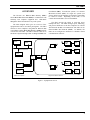
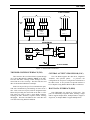
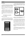
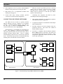
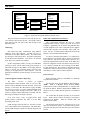
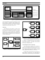
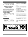
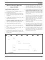
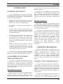
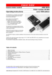
LBI-38961A Technical Description EDACS® Data Gateway ericssonz LBI-38961 TABLE OF CONTENTS Page PREFACE .................................................................................................................................... 4 SPECIFICATIONS ...................................................................................................................... 5 OVERVIEW................................................................................................................................. 7 FEATURE LIST .......................................................................................................................... 8 SYSTEM ARCHITECTURE ....................................................................................................... 8 TRUNKED SYSTEM INTERFACE (TSI)............................................................................. 9 CENTRAL ACTIVITY PROCESSOR (CAP) ........................................................................ 9 HOST DATA INTERFACE (HDI)......................................................................................... 9 EDG SIZING ......................................................................................................................... 10 NETWORKING CONCEPTS ...................................................................................................... 10 SINGLE NETWORKS........................................................................................................... 10 BRIDGING HOSTS AND EDACS NETWORKS.................................................................. 11 CONNECTING MULTIPLE NETWORKS ........................................................................... 12 INTERFACE SPECIFICATION .................................................................................................. 13 RDI HOST DATA INTERFACE ........................................................................................... 13 Protocol Layers..............................................................................................................................13 Addressing ....................................................................................................................................13 Acknowledgments and Error Reporting.........................................................................................13 Queuing and Flow Control ............................................................................................................13 IP HOST INTERFACE .......................................................................................................... 13 Protocol Layers..............................................................................................................................13 Addressing ....................................................................................................................................14 Acknowledgments and Error Reporting.........................................................................................14 Queuing and Flow Control ............................................................................................................14 RADIO DATA TERMINAL (RDT) INTERFACE................................................................. 15 Messaging Between the EDG and Radio........................................................................................15 Queuing and Flow Control ............................................................................................................15 Anti-Biasing Protection.................................................................................................................15 RDTs without a Network Layer .....................................................................................................15 Protocol Layers.......................................................................................................................15 Addressing .............................................................................................................................16 Acknowledgments and Error Reporting ..................................................................................16 RDTs with a Standard Network Layer ...........................................................................................16 Protocol Layers.......................................................................................................................16 Addressing .............................................................................................................................17 Acknowledgments and Error Reporting ..................................................................................17 RDTs with a Null Network Layer ..................................................................................................17 Protocol Layers.......................................................................................................................17 Addressing .............................................................................................................................18 Acknowledgments and Error Reporting ..................................................................................18 ADDRESS CONVERSIONS AND MESSAGE ROUTING ......................................................... 19 RDI HOST COMPUTERS AND NON-NETWORK LAYER RDTS ..................................... 19 IP HOST COMPUTERS AND NETWORK LAYER RDTS .................................................. 19 Message from Host to RDT ...........................................................................................................19 Message from RDT to Host ...........................................................................................................19 Copyright June 1995, Ericsson Inc. 2 LBI-38961 TABLE OF CONTENTS (CON’T) Page IP HOST COMPUTERS AND NON-NETWORK LAYER RDTS .........................................20 Message from Host to RDT........................................................................................................... 20 Messages from RDT to Host ......................................................................................................... 20 MESSAGE FLOW WITHIN THE EDACS SYSTEM ..................................................................21 RADIO ORIGINATED MESSAGE........................................................................................21 RADIO DESTINED MESSAGE ............................................................................................22 OPTIMIZATIONS........................................................................................................................23 MAXIMIZING RF EFFICIENCY ..........................................................................................23 LOAD DISTRIBUTION FOR RADIO ORIGINATED MESSAGES......................................23 RDTs Without a Network Layer.................................................................................................... 23 RDTs With a Network Layer ........................................................................................................ 23 COMPONENT DESCRIPTION ...................................................................................................23 CENTRAL ACTIVITY PROCESSOR (CAP) ........................................................................23 Adapter Board .............................................................................................................................. 24 Transition Module ........................................................................................................................ 24 VCOM24 SERIAL COMMUNICATIONS CONTROLLER...................................................24 VMEADAPT Module................................................................................................................... 24 SCI-232........................................................................................................................................ 24 FIXED DISK DRIVE .............................................................................................................24 FLOPPY DRIVE ....................................................................................................................24 DIAGNOSTIC TERMINAL...................................................................................................25 MODEM UNIT SHELF..........................................................................................................25 Modem Interface Module.............................................................................................................. 25 Rockwell Modem.......................................................................................................................... 25 CROSS CONNECT PANEL ..................................................................................................25 POWER SUPPLY ..................................................................................................................25 FAN .......................................................................................................................................25 BACKPLANE ........................................................................................................................25 CREDITS: EDACS is a registered trademark of Ericsson Inc. EDG is a trademark of Ericsson Inc. MS-DOS is a trademark of Microsoft Corporation. 3 LBI-38961 PREFACE This is one of four manuals for the EDACS Data Gateway (EDG™). It contains a detailed description of the EDG capabilities, interfaces and hardware. Other relevant documents are: EDG Installation and Maintenance (LBI-38962): This manual contains installation and troubleshooting information. This manual also includes the boot sequence and network planning. EDG User's Reference Manual (LBI-38963): This manual contains information for using the EDG command shell. The command shell services the Diagnostic Terminal and Telnet logins. EDG Configuration Reference Manual (LBI-38964): This manual documents the commands used to configure the EDG. Internetworking with TCP/IP, Volume I, by Douglas E. Comer: This is an excellent (but unofficial) source of information about Internet Protocol. EDACS Network Driver User’s Manual (LBI-39161) This manual documents how to install and use the EDACS Network Driver (END). This product provides a Medium Access Control (MAC) sublayer driver for use with off-the-shelf IP protocol stack products. The END product is for use with MS-DOS. EDACS CommServ Programmers Guide (LBI-38835): This manual documents the CommServ product. CommServ provides an application program interface that simplifies RDT programming by providing an RDI Data Link Layer. It is for use with MS-DOS and PC-DOS. Radio Data Interface Protocol Specification, Version 1.92 (ECX 922) This manual documents the RDI Interface. 4 LBI-38961 SPECIFICATIONS EDACS Interface Physical Layer Up to 8 control lines operating at either 19,200 or 9600 bps Up to 32 data lines (minus the RDI Host Interface connections) operating at 9600 bps Data Link Layer EDACS Proprietary Network Layer EDACS Network Layer (selectable on a per unit and group basis) RDI Protocol Host Interface Physical Layer Up to 16 RS-232 data lines operating at 9600 bps, using DB25 connectors Data Link Layer RDI Protocol, versions 1.8a, 1.91, and 1.92 Network Layer None Internet Protocol Host Interface Physical Layer DB15 AUI Ethernet Connector Data Link Layer Ethernet II, aka IEEE 802.3 DIX Network Layer Internet Protocol (IP), Version 4 General Specifications Diagnostic Terminal RS-232 serial interface supporting VT100 type terminals or remote access via Telnet Printer Centronics parallel printer interface Drives 245 Mbyte fixed disk drive with SCSI interface 1.44 Mbyte, 3.5" removable diskette drive with SCSI interface. MS-DOS format diskettes supported. EMI Regulations Conforms to FCC 20780 Part 15 Subpart J, A, and EN 55022 Class B Safety Conforms to EN 60950, UL 1459, and CSA 225 Power Supply Input Voltage (Autosensing) 110 VAC ± 10%, 60 Hz 220 VAC ± 10%, 50 Hz single phase Output Voltage ± 12 volts DC at 10 amps each + 5 volts DC at 100 amps Remote Sense For all three channels Over Voltage Protection 120% to 130% of nominal output on all channels Over Current Protection On all channels Line Regulation 0.2% of rated output Load Regulation 0.8% of rated output Ripple 1% peak to peak at 50 MHz Dynamic Response 3% max deviation to 25% - 75% step change Filtering Power line filter and internal filter for conducted emissions Status Indicators AC "POWER ON" indicator 5 LBI-38961 Average Power Consumption EDG with no ports 280W Each group of 4 TSI Ports 70W Each group of 4 HDI Ports 40W Fan Power requirements 12 VDC (from power supply) Air flow rate 250 CFM Filter Removable aluminum filter Physical (EGE Standard Cabinet) Cabinet Colors Housing Light Gray Trim Black Cabinet Dimensions Height 69 1/6" (175.5 cm) Width 24" (61 cm) Depth 24" (61 cm) Material 16 gauge cold rolled steel Status Inputs and Outputs Board LEDs General Purpose CPU FAIL, STATUS, RUN, and SCON Intelligent Serial I/O Controller RUN, HALT, and SYSFAIL Drive LEDs Disk activity lamps on both drives Fan LED 12 VDC power indicator lamp Remote Reset Input Connector Shorting the Remote Reset pins on front panel of CAP Board forces a system RESET Environmental Temperature Operating 0 to + 40° C Non-Operating -20 to +85° C Humidity Diagnostics Error Detection 6 to 95% noncondensating (except for removable diskette drive) Run-time errors logged in a file for viewing or printing System Configuration Configuration file can be viewed from the Diagnostic Terminal. Controlled Shutdown System operator can cause a graceful system shutdown so calls in progress are completed LBI-38961 OVERVIEW The Ericsson Inc. EDACS Data Gateway (EDG) allows Radio Data Terminals (RDT) to communicate with stationary host computer equipment and other RDTs through the EDACS trunked two-way radio system. The block diagram below gives an overview of the equipment that can be used when passing data. The EDG connects to host computers using Internet Protocol (IP) over Ethernet and/or Radio Data Interface (RDI) protocol over RS-232 serial links. The EDG connects to the rest of the EDACS System through either an Integrated Multi-site IP Host Coordinator (IMC), for multi-site systems, or a Console Electronics Control (CEC) for single site systems (not shown). RDTs use the 9600 bps serial interface of the RDIs to connect to radios. Depending on the radio, it can contain an internal RDI or use an external RDI. The EDG provides the ability to send data across multiple RF sites. The EDG manages speed, addressing, and protocol differences so IP Host Computers on a Local Area Network (LAN) can communicate with radios on an EDACS Wide Area Network (WAN). In addition, the EDG can be configured to minimize or eliminate custom communications software. IP Host SITE Radio & RDI Radio Ethernet Network & RDI RDT RDT IP Host EDG IMC Radio & RDI RDT RDI Host SITE Radio RDI Host RDI Host Computers & RDI RDT Single Node EDACS Network Figure 1 - Equipment Overview 7 LBI-38961 ⇒ The EDG helps prevent data corruption due to radio biasing. FEATURE LIST The Ericsson EDACS Data Gateway supports the following features: • • • • • • 8 Call Types: ⇒ Individual Data Call. ⇒ Host Originated Group Data Call (Multi-site or Single site). ⇒ Radio-to-Radio Data Calls (via the EDG). Non-Proprietary Host Computer Interface (64K bytes per message): ⇒ Ethernet physical connection and Data Link Layer ⇒ Standard IP Network Layer supporting class A, B, or C IP addresses. ⇒ Simultaneous use of multiple Transport Layer Protocols (TCP, UDP, or customer defined). Proprietary Host Computer Interface (512 bytes per message): ⇒ RS-232 Physical connection. ⇒ RDI Data Link Layer with positive acknowledgment. Protocol Conversion: ⇒ The EDG converts data messages, addresses, and error messages between the various interface types. Flow Control and Queuing: ⇒ The EDG manages the speed differential between the various interface types. Configurable queues and message timers are available for messages destined for radios and RDI Hosts. Queuing is not needed for IP Hosts due to the 10 MHz speed of the interface. Robust Operation: ⇒ The EDG continues call processing when an EDACS System is in Failsoft. • • • • Flexible Configuration ⇒ The EDG is configured through an ASCII text file. The configuration can be verified on an MS-DOS PC. Error Logging: ⇒ The EDG can log detected errors to a disk file, the Diagnostic Terminal, a remote terminal, and/or to a printer, as desired. Three levels of reporting can be selected. Remote Login and File Transfer: ⇒ The EDG can be accessed using Telnet to login or FTP for file transfer. ⇒ Remote Software Upgrades are supported. Statistics Gathering and Display: ⇒ The EDG maintains loading statistics that can be displayed and cleared as desired. SYSTEM ARCHITECTURE The block diagram below shows the system architecture of the EDACS Data Gateway, its external interfaces to the rest of the EDACS System, and the EDGs external interfaces to host computer equipment. The EDG can be configured with either an IP Host Interface, RDI Host Interfaces, or both. The TSI, HDI and CAP boards communicate over the system bus. One or more Trunked System Interface (TSI) Boards handle all communications to the rest of the EDACS trunked radio system. The Central Activity Processor (CAP) provides the IP Ethernet Interface to host computers and system services such as disk I/O, printing, and the local Diagnostic Terminal interface. Optional Host Data Interface (HDI) Boards provide an interface to host computers using RDI Protocol. LBI-38961 IMC/CEC DATA INTERFACE MODULE CONTROL LINK ROCKWELL MODEMS TRUNKED SYSTEM INTERFACE TO HOST COMPUTERS ROCKWELL MODEMS HOST DATA INTERFACE TRUNKED SYSTEM INTERFACE (MASTER) (SLAVE) (PORTS 1 - 4) (PORTS 5 - 8) (PORTS 1 - 4) VME SYSTEM BUS Printer Centronics (optional) FIXED CENTRAL ACTIVITY PROCESSOR DISK RS-232 FLOPPY DISK Diagnostic SCSI BUS Terminal Ethernet TO HOST COMPUTERS Figure 2 - Internal EDG Architecture TRUNKED SYSTEM INTERFACE (TSI) CENTRAL ACTIVITY PROCESSOR (CAP) TSIs connect to the rest of the EDACS System through one or more Data Interface Modules (DIM) in the IMC. The TSIs and IMCs exchange control messages over the control link at 19.2k or 9.6k bps. The TSIs and sites send data via the Rockwell Modems at 9600 bps. The CAP Board supports the disk drives, Diagnostic Terminal, and optional printer. It processes the configuration file and passes configuration information to the other boards. It also provides an optional interface to host computers using Internet Protocol (IP) over Ethernet. Each TSI can provide up to four communication ports, with each communication port handling one data call at a time. TSIs can be used in pairs, with one designated as the Master and providing the control link to the IMC or CEC. This allows two TSIs to share a single DIM Controller, reducing the IMC hardware required without reducing throughput. The EDG and EDACS Sites send data calls over audio lines using Rockwell Modems. HOST DATA INTERFACE (HDI) Each HDI Board can support up to four ports. The ports are individually assigned to hosts, allowing a single HDI to support multiple hosts, multiple HDIs to support a single host, or multiple HDIs to support multiple hosts. 9 LBI-38961 EDG SIZING The number of TSI Boards should be selected based on the expected load. This should include expected messaging between IP Host Computers and radios, between RDI Host Computers and radios, and between radios. For most applications, one TSI Board is needed for each HDI Board (if any). This is in addition to any TSI Boards needed to support the expected load from the other message paths listed previously. While most configurations only require two or three TSI and HDI Boards, an EDG can support up to eight TSI or HDI Boards. For example, if only IP Host Computers are used, up to eight TSI Boards could be used. If RDI Host Computers are used, up to four TSI Boards and four HDI Boards could be used. If both host interfaces are used, a full EDG might consist of five TSI Boards and three HDI Boards. Any device wishing to communicate with devices on a network must directly connect to the network using an interface that is compatible with the network. A simple network could connect three host computers to each other using Ethernet. Host A Host C Host B NETWORKING CONCEPTS Figure 4 - Ethernet Network SINGLE NETWORKS For the purposes of this discussion, a network is a physical media and protocol that allows multiple devices to communicate. In the terms of the International Standards Organization's Open System Interconnection Reference Model (OSI Model), these are the Physical and Data Link Layers. Application Layer Presentation Layer Session Layer Transport Layer Network Layer Data Link Layer Physical Layer Figure 3 - OSI Model 10 Each of the devices would physically connect to the Ethernet cable. They would communicate with each other using Ethernet Addresses and Ethernet Protocol. Unfortunately, there is no single type of network that is best for all situations. Ethernet networks perform well when used to connect devices at the same location. However, Radio Data Terminals (RDTs) could not be used in mobile applications if they were connected to an Ethernet cable running through a building. This leads to multiple network types to solve different networking needs. The devices on the Ethernet Network use Ethernet cable as their physical media and use Ethernet Addresses and protocol to communicate. The devices on the EDACS RF-Data Network use radio frequencies as their physical media and use EDACS Addresses and protocol to communicate. This configuration works well until an RDT on the EDACS Network needs to communicate with a host on a different site or on the Ethernet Network. The EDG provides two solutions to this problem that can be used individually or together. LBI-38961 Radio & RDI Host A Host C Radio SITE & RDI RDT RDT Host B Radio & RDI Host D EDACS RF-Data Network Ethernet Network Figure 5 - Two Unconnected Networks Radio & RDI RDT SITE Host A Radio & RDI RDT Host B EDG IMC Host C Radio & RDI Host D RDT SITE Radio & RDI Host Computers RDT EDACS Network Figure 6 - Host Computers Bridged To an EDACS Network BRIDGING HOSTS AND EDACS NETWORKS The EDG can be used as a bridge between RDTs on an EDACS Network and host computers using the RDI Host Data Interface. Connecting host computers and RDTs by bridging has the following advantages: 1. Host computers and RDTs can communicate regardless of the RF site the radio is logged into. 2. A single host computer can communicate with multiple radios simultaneously. 3. Host computers and their applications can easily be migrated from single site EDACS RF-Data Networks to bridged networks. 11 LBI-38961 4. Host computers can receive a positive acknowledgment that their message has been received by the radio. 5. RDI Protocol can be implemented in RDTs with limited processing power. While the network layer address provides a consistent address across an internet, it cannot be used to actually send data across a specific network. The network layer address must be converted to a data link layer address specific to the network type. 6. Several third party message switches (protocol converters) exist based on this configuration. Connecting host computers and RDTs by Internetworking has the following advantages: CONNECTING MULTIPLE NETWORKS The EDG can also be used as a gateway between EDACS Networks and host computers on an Ethernet Network. Connecting multiple networks, even if they are the same type, is known as Internetworking. The connected networks become a single internet. Internetworking is accomplished by performing two actions. First a gateway is connected to both networks. The gateway has an interface to each network and is able to translate messages between them. Next, to simplify internetworking, a network layer is used above the data link layers. The network layer provides a consistent addressing method, protocol, and interface across the internet. 1. Host computers and RDTs can communicate regardless of the RF site the radio is logged into. 2. A single host computer can communicate with multiple radios simultaneously. 3. The EDG connects to the host computer using nonproprietary protocols. This reduces the amount of custom software required. 4. The EDG is compatible with the EDACS Network Driver (END) software for the RDT. This allows the use of off-the-shelf IP protocol stack products. In this configuration, applications written for TCP and UDP can be used or developed. Radio & RDI RDT SITE Host A Host C Radio & RDI RDT Host B EDG IMC Radio & RDI Host D Radio & RDI Ethernet Network EDACS Network Figure 7 - Internetworking Using an EDACS Data Gateway (EDG) 12 RDT SITE RDT LBI-38961 INTERFACE SPECIFICATION between the EDG and the host is complete. If the RDI Host Computer does request confirmation, the EDG frees the host port after returning the confirmation. RDI HOST DATA INTERFACE Protocol Layers RDI Hosts physically connect to EDG Host Data Interface (HDI) ports via one or more 9600 bps asynchronous serial links. The data link layer supports RDI Protocol. Version 1.92 is recommended for new applications. Versions 1.91 and 1.8a are supported for existing applications. In addition to the standard RDI Protocol features, the minimum time before retrying a message is not a fixed 45 seconds. The EDG can be configured to raise or lower this time. For more information, see the MSG_TIMEOUT command in the EDG Configuration Reference Manual (LBI-38964). If the RDI Host is using MS-DOS, the CommServ product can be used to reduce the coding effort. The EDACS CommServ Programmers Guide lists the minimum requirements for using CommServ. There is no network layer on RDI Hosts. While it is doubtful that an RDI Host would be used to communicate with an RDT with a network layer, there are no restrictions to prevent this. In this case, the EDG would add the network layer for messages to the RDT and strip the network layer for messages from the RDT. The protocols used above the network layer are of no interest to the EDACS System. Any headers used by these protocols look like part of the data message to the EDACS System. Addressing RDI Hosts and radios communicate using EDACS Addresses. EDACS Addresses can be assigned to hosts, individual radios, and to groups of radios. Acknowledgments and Error Reporting The RDI Host receives a positive or negative acknowledgment from the HDI when it receives a data transfer request (XFERB) and again when the HDI receives the message. If selected in the data transfer request, the RDI Host also receives confirmation based on the reception of the message by the radio/RDI. There is no positive or negative acknowledge back to the RDI Host after the message leaves the radio. If the RDI Host does not request confirmation, the EDG frees the host port immediately after the data transfer If an error occurs, it may be logged at the EDG, another EDACS component, the radio, or at the RDI, depending on the type of the error. Queuing and Flow Control Each HDI board has approximately 300K bytes of buffer space for queuing messages to the host computer. The HDI uses this queue when all of the ports to the host are busy. Conversely, the TSIs queue messages to radios, if necessary. If an RDI Host Computer and the EDG try to initiate a data transfer over the same port at the same time, the EDG queues its message and services the host's transfer first. When a port frees up, the EDG sends out the message that was preempted before sending out any other queued messages. IP HOST INTERFACE Protocol Layers The EDG physically connects to an Ethernet Network using a DB15 AUI Ethernet Connector. This can be used with thick coax, thin (BNC) coax, or twisted pair (10BaseT) using an IEEE 802.3 standard off-the-shelf transceiver. The transceiver is purchased separately based on the network requirements. The data link layer uses Ethernet II Protocol. This is also known as IEEE 802.3 DIX. Standard IEEE 802.3 Ethernet Protocol is not supported at this time. The network layer uses Internet Protocol (IP), version 4. The Internet Activities Board defines the official standard for the Internet Protocol. Internetworking with TCP/IP, Volume I, by Douglas E. Comer is an excellent, but unofficial, source of information about IP. Except for the following, the EDG fully supports the major features of the Internet Protocol: 1. Subnetting is not supported at this time. 2. A Host ID of all ones does NOT refer to all radios on an EDACS network. The protocols that are used above the network layer are end-to-end conversations between the host and RDT. Any headers they use are simply passed as data through the network to the RDT. Except for the Transport Layer 13 LBI-38961 Protocol when the RDT is using a Null Network Layer, the upper protocols are of no concern to the EDACS System. The RDT Interface section explains this more fully. Addressing From the host's perspective, the RDTs are peer devices on another network. In a simple configuration, the EDG is the next gateway to use to send data to the RDTs. In a more complex configuration, there could be multiple gateways between the EDG and the host. In either case, the host is only concerned with the next gateway to use, not the full topology of the internet. protocol layers. The EDACS System generates an error indication if an error occurs after the EDG receives a message and before the radio acknowledges the receipt of the message. Unsuccessful messages may generate one of the following error indications: 1. Error return codes from system calls on the host computer. These error codes and their meanings vary depending on the host type. 2. Internet Control Message Protocol (ICMP) messages. The EDG or another component in the host network may return ICMP messages. If an error occurs sending an ICMP message back to the host, the ICMP message is dropped. The EDG Installation and Maintenance Manual contains a list of the ICMP Messages the EDG returns. The EDG Installation and Maintenance Manual contains information on the format of IP Addresses and assigning them. On most host computers, ICMP messages are not returned to the application program that sent the original message. If desired, a program could be written to receive all ICMP messages, filter those of interest, and return them to the application program on request. RDT Host EDG RDT Host 3. Errors logged by other components in the network. host 4. Errors logged by the EDG. The severity of errors logged by the EDG is selectable. See the log command in the EDG User's Reference Manual for more information. 5. Errors logged by other EDACS components such as the IMC, Site Controller or radio/RDI. RDT Host Network EDACS RF Network Figure 8 - Simple Configuration As Seen By the Host At the data link layer, the EDG and host computers communicate using Ethernet Addresses. The host computers and theEDG useAddress Resolution Protocol (ARP) to learn each others Ethernet Addresses based on their IP Addresses. The network layer uses the IP Address to decide where to route the message next. For host originated messages, the host addresses a radio or group of radios using the unique IP Address assigned to each radio and group. Normally, the host has a single entry added to its routing table instructing it to use the EDG's CAP Board as the next gateway for messages being sent to any destination on the EDACS Network. For messages from a radio to a host, the EDG receives the message, examines the IP Address and forwards the message on to the host computer. Acknowledgments and Error Reporting The IP Network Layer is a best-effort delivery system. Successful messages are not acknowledged. Typically, a positive acknowledgment is built into one of the higher 14 It is also possible for a message to successfully reach the radio and the acknowledgment to fail to reach the EDG. In this case, the EDACS System treats the message as if it errored even though the radio, RDI, and RDT see it as a successful message. The EDG will send an ICMP Message back to the host computer. Queuing and Flow Control The EDG's IP Host Interface uses several queues to send and receive IP fragments. Under normal conditions, fragments spend very little time in these queues. In extreme cases, the IP Host Interface could receive messages at a faster rate than it can handle. In this situation, the interface accepts as many messages as it can and issues ICMP Source Quench messages for the rest. LBI-38961 RADIO DATA TERMINAL (RDT) INTERFACE RDTs can be configured in a variety of ways. Normally, the RDT configuration is chosen for close compatibility with the type of host interface. Generally, if the host has a network layer, then the RDT should also have a network layer. If the host does not have a network layer, then the RDT should not have a network layer. However, this is not required. The EDG compensates if an unbalanced configuration is chosen. The network layer software on the RDT can either be provided by Ericsson or be supplied by the customer. The EDG's configuration tells it which RDTs (radios) use a network layer. In addition to enabling or disabling the network layer for all radios, the RDTs can be configured individually or in ranges. Messaging Between the EDG and Radio The data link layer protocol used between the EDG and the radios is a hardened protocol designed specifically for the RF environment. If necessary, portions of the message may be repeatedly transmitted in order to complete the data call. Once a call has been established (working channel assigned), the EDG and radio attempt to get the message through for up to seven seconds before giving up. EDG sends the source an ICMP Source Quench message asking it to reduce its output rate. If the EDG is saturated, it sends the source of the message an ICMP control message asking it to reduce its output rate. The EDG also deletes messages that have been queued for the specified time, and limits the number of messages queued. Anti-Biasing Protection Large messages that contain a disproportional amount of either binary zeros or ones can bias a radio, causing an increase in failed messages. Some radios have a greater ability to resist biasing than others, but most radios are susceptible. The EDG can be configured to support Bias Reduction Encoding (BREN). Before sending a message to a radio, the EDG encodes the message to balance the number of binary zeros and ones. The receiving RDI decodes the message before forwarding it to the RDT. For radio originated messages, the EDG decodes messages encoded by the RDI. This feature may increase or decrease the overall throughput, depending on the reduction in retries verses the additional BREN overhead. RDTs without a Network Layer This configuration is useful when communicating with an RDI Host Computer. Queuing and Flow Control Protocol Layers Each TSI Master has approximately 300K bytes of buffer space for queuing messages to radios. Conversely, the HDIs queue messages to RDI Host Computers, if necessary. RDTs physically connect to radio/RDIs via a 9600 bps asynchronous serial link. If the EDG's first attempt to send a message to a radio fails because there are no working channels available or because the radio is in a voice call, the EDG tries three additional times at 2 second intervals to get a channel before giving up on the call. If all of the attempts fail, the The data link layer uses RDI Protocol. If the RDT is using MS-DOS, the CommServ product can be used to reduce the coding effort. The EDACS CommServ Programmers Guide lists the minimum requirements for using CommServ. 15 LBI-38961 Application Application and Transport and Transport Commserv Commserv Commserv (Data Link Layer) RS-232 RS-232 RS-232 (Physical Layer) RDI Host EDACS System RDT Figure 9 - Typical Protocol Stack With No Network Layer. The protocols that are used above the network layer are of no interest to the EDACS System. Any headers used by these protocols look like part of the data message to the EDACS System. Addressing RDI Hosts and radios communicate using EDACS Addresses at the data link layer. An RDT can access a maximum of sixty-three different hosts. The EDG routes the messages to and from the host. The EDG is transparent to both the host and the RDTs. Since there is no network layer, there is no network layer address. In this configuration, RDTs can only send individual messages to hosts. RDTs cannot send group messages or individual messages to other RDTs. If messaging between radios is desired, the originating RDTs must send the message to an application on a host computer. The host application would then send the message on to the desired radio(s). RDTs with a Standard Network Layer This configuration eliminates the need for custom communications software when used with an IP Host computer. Applications can be written using standard TCP or UDP transport layers. This configuration also supports radio-to-radio messages and messages larger than 512 bytes. The use of Telnet terminal emulation and FTP file transfer is not recommended at this time. To achieve maximum performance, it is important to keep collisions to a minimum. This is true for any transport layer. However, with TCP's sliding window protocol, it is especially important that protocol stacks in the RDTs and Hosts are configured correctly. The EDACS Network Driver User’s Manual contains the correct settings for the RDT. In some situations, the TCP software in the Host cannot be configured to reduce collisions to an acceptable level. Using UDP may be a better solution in these situations. Protocol Layers Acknowledgments and Error Reporting RDTs physically connect to radio/RDIs via a 9600 bps asynchronous serial link. The RDT receives a positive or negative acknowledgment from the RDI when it receives a data transfer request (XFERB) and when the RDI receives the message. If selected in the data transfer request, the RDT also receives a positive or negative acknowledgment based on the reception of the message by the EDG. There is no positive or negative acknowledge back to the RDT after the EDG begins sending the message to the host. The data link layer uses the EDACS Network Driver (END). END is a Medium Access Control (MAC) sublayer driver for PCs running MS-DOS. It complies with the Network Driver Interface Specification (NDIS) and advertises itself to off-the-shelf IP products as an Ethernet Driver. If an error occurs, it may be logged at the EDG, another EDACS component, the radio, or at the RDI, depending on the error. An off-the-shelf IP product provides an IP Network Layer. END converts between IP headers and EDACS Network Layer Headers. END also handles ARP and RARP requests locally. ICMP messages from IP Hosts are not used to return error codes to RDTs in this configuration. The EDG filters out all ICMP messages to RDTs except Echo Requests and Replies. The protocols used above the network layer are of no interest to the EDACS System. Any headers used by these protocols look like part of the data message to the EDACS System. 16 LBI-38961 Applications Applications TCP/UDP TCP/UDP (Transport Layer) IP IP EDACS NL Ethernet Ethernet RDI END (Data Link Layer) Coax Coax RS-232 RS-232 (Physical Layer) IP/Ethernet Host IP EDACS System (Network Layer) RDT Figure 10 - Typical Protocol Stack With a Standard Network Layer. Addressing RDTs with a Null Network Layer The various layers in the protocol stack use several different types of addresses to perform different functions. This configuration is useful in situations similar to those where a customer supplied network layer on the RDT would be useful. In both situations IP host computers are used, but END is not used. The primary difference is that radio-to-radio messages, messages larger than 512 bytes, and multiple transport layer protocols are not needed. Since the mobile applications developer is not using the network layer functionality, the layer can be omitted. At the data link layer, the EDG and radios communicate using EDACS Addresses. For a message to a radio or group, the EDG uses a configuration table to convert the IP Address to the EDACS Address. For messages from radios, the EDG reserves the EDACS Addresses one through fifteen. END sequences through these addresses to distribute the load in case the EDG is configured with multiple TSI Masters. All radio originated messages are sent to the EDG, even messages to another radio. The network layer uses the IP Address to route the message to a host, another radio, or a group of radios. An RDT can access the full range of IP Addressable hosts. The main difference between this configuration and RDTs without a network layer is that this is an "unbalanced configuration". The hosts use a network layer, but the RDTs do not. Protocol Layers RDTs physically connect to radio/RDIs via a 9600 bps asynchronous serial link. Acknowledgments and Error Reporting At the data link layer, END uses positive acknowledgment. The RDT receives a positive or negative acknowledgment from the RDI when it receives the data transfer request, when the RDI receives the data, and when the EDG receives the data. There is no positive or negative acknowledge back to the RDT after the data leaves the EDG. END returns the status back up to the IP product. At the network layer, the IP product may receive an ICMP message as a negative acknowledgment. If an error occurs, it may be logged at the host, other components in the Ethernet Network, the EDG, the radio, the RDI, or another EDACS component, depending on the error. 17 The data link layer uses RDI Protocol. If the RDT is using MS-DOS, the CommServ product can be used to reduce the coding effort. The EDACS CommServ Programmers Guide lists the minimum requirements for using CommServ. There is no network layer on the RDTs. For radio originated messages, the EDG adds a network layer. For messages to the radios, the EDG strips the network layer. It is expected that a relatively simple transport layer protocol such as UDP would be used above the network layer and the application would provide some transport layer services such as performing retries. Normally the transport layer protocol is of no concern to the EDACS System and there are no restrictions placed on it. However in this configuration, only one transport layer protocol can be used at a time. The IP Network Layer Header contains a LBI-38961 Applications Applications and some Transport and some Transport UDP UDP (Minimal IP IP Ethernet Ethernet RDI Coax Coax RS-232 Null NL Null NL (Network Layer) RDI (Data Link Layer) (Physical Layer) RS-232 EDACS System IP/Ethernet Host Transport Layer) RDT Figure 11 - Typical Protocol Stack with a Null Network Layer. Protocol field which is used by the network layer on the host computer to determine which transport layer protocol to pass the data up to. Because the IP Network Layer Header is built by the EDG, it must be configured with the protocol the customer wishes to use. Addressing The addressing in this situation is a hybrid of the network layer and non-network layer methods. From the host's perspective, the RDTs are peer devices on another network, just as in any network layer configuration. However, from the RDTs perspective, the host is on the EDACS Network. An RDT can access a maximum of sixty-three different hosts. Radio & RDI RDT Radio & RDI RDT Radio & RDI Host SITE Radio & RDI RDT Host EDG RDT Host RDT Host Network EDACS RF Network Figure 12 - Configuration As Seen By the Hosts Host Figure 13 - Configuration As Seen By the RDTs The host computers send and receive messages using IP Addresses. The RDTs send and receive messages using EDACS Addresses. The EDG converts between them using a configuration table. Acknowledgments and Error Reporting At the data link layer, the RDT receives a positive or negative acknowledgment from the RDI when it receives the data transfer request and when the RDI receives the data. The data link layer can ask for a positive acknowledgment when the EDG receives the data. The EDG filters outs network layer error messages to RDTs without a network layer. The EDG drops all ICMP messages except Echo Requests and Echo Replies. 18 LBI-38961 If an error occurs, it may be logged at the host, other components in the Ethernet Network, the EDG, the radio, the RDI, or another EDACS component, depending on the error. ADDRESS CONVERSIONS AND MESSAGE ROUTING Installations may contain additional equipment between the host computers and the EDG. Possible address conversions and message routing performed by additional equipment is not documented in this manual. RDI HOST COMPUTERS AND NONNETWORK LAYER RDTS RDI Hosts and radios communicate using only EDACS Addresses. The EDG is a transparent bridge between them and does not perform any address conversions. IP HOST COMPUTERS AND NETWORK LAYER RDTS Ethernet Address, it uses Address Resolution Protocol (ARP) to ask the CAP Board. 2. The CAP Board forwards the message to a TSI Board. 3. The TSI Board converts the destination IP Address to either an EDACS Logical ID (LID) or Group ID (GID). The TSI Board then sends the message to a radio or group of radios. 4. The radio/RDI sends the message to the RDT using an XFERB command. The EDACS Network Layer Header contains the IP Address of the host. The TSI Board uses one of the LIDs assigned to it as the source EDACS Address in the XFERB. Message from RDT to Host 1. The RDT sends the message to the radio/RDI using an XFERB command. The EDACS Network Layer Header contains the IP Address of the host. The destination EDACS Address in the XFERB is one of the IDs in the block assigned to the EDG. 2. One of the TSI boards receives the message from the radio. The TSI routes the message on to the CAP (or out to another radio) based on the IP Address in the Network Layer Header. 3. If the message is to a host, the CAP Board forwards it using its Ethernet Address. If the CAP does not know the host's Ethernet Address, it uses ARP to ask the host. Message from Host to RDT 1. The host looks up the RDT's IP Address in its routing table and finds the IP Address of the EDG's CAP Board listed as the next gateway for the EDACS Network. The host then forwards the message to the CAP Board using its Ethernet Address. If the host does not know the CAP Board's Host A Host B EDG EDG CAP TSI Ethernet Network Internal EDG Network SITE Radio & RDI RDT CEC Radio & RDI RDT EDACS Network Figure 14 - IP Host Computers And Network Layer RDTS 19 LBI-38961 4. IP HOST COMPUTERS AND NONNETWORK LAYER RDTS Message from Host to RDT 1. Messages from RDT to Host The host looks up the RDT's IP Address in its routing table and finds the IP Address of the EDG's CAP Board listed as the next gateway for the EDACS Network. The host then forwards the message to the CAP Board using its Ethernet Address. If the host does not know the CAP Board's Ethernet Address, it uses ARP to ask the CAP Board. 2. The CAP Board forwards the message to a TSI Board. 3. The TSI Board converts the host's IP Address to an EDACS Logical ID (LID). The TSI Board converts the destination IP Address to either an EDACS Logical ID or Group ID (GID). The TSI Board then sends the message to a radio or group of radios. Host A Host B The radio/RDI sends the message to the RDT using an XFERB command. It contains the EDACS LID of the host. EDG EDG CAP TSI Ethernet Network Internal EDG Network 1. The RDT sends a message to the contains the EDACS LID of the host. 2. The radio sends the message to a TSI board on the EDG. 3. The TSI Board converts the radio and host LIDs to IP Addresses. It then forwards the message to the CAP Board. 4. The CAP Board forwards the message to the host using its Ethernet Address. If the CAP Board does not know the host's Ethernet Address, it uses ARP to ask the host. SITE Radio & RDI RDT CEC Radio & RDI RDT EDACS Network Figure 15 - IP Host Computers And Non-Network Layer RDTS 20 radio/RDI. It LBI-38961 MESSAGE FLOW WITHIN THE EDACS SYSTEM RADIO ORIGINATED MESSAGE The following provides a simplified call flow for a radio to host data message transfer. 1. The Radio Data Terminal (RDT) begins transferring a message to the Radio Data Interface (RDI) using RDI 1.92 protocol. 2. The RDI begins pipelining the message to the radio using Mobile Signaling Protocol. 3. The RDI acknowledges to the RDT that it has successfully received the message. This may occur earlier or later depending on the size of the message. 4. The radio informs the site that it has a message. 5. The site assigns a working channel and informs the radio. 6. The site sends the call assignment to the IMC. The IMC sends it on to the EDG. 7. The EDG selects a TSI Port and informs the IMC. The IMC sets up a data path between the EDG and the working channel. RDT RDI Radio Site 8. The radio acknowledges to the RDI that it has successfully received the message. This may occur earlier or later depending on the size of the message. 9. The radio breaks the message down into packets and sends the first burst of packets to the site. The site forwards the burst to the EDG as it receives it. After the EDG receives the entire burst, it sends an Ack Map back to the radio, informing it of the packets the EDG correctly received. If necessary, the radio sends another burst containing packets the EDG did not correctly receive and packets that the radio has not previously sent. This sequence continues until the EDG receives the entire message or until the radio exhausts its retries. 10. The radio tells the RDI the status of the message transmission to the EDG. 11. If the EDG successfully received the message, the EDG sends the message to the destination. The message transfer from the EDG to the destination proceeds independently of any other signaling from the RDT. 12. If requested, the RDI tells the RDT whether the EDG successfully received message or not. Note that the RDT does not receive any direct confirmation the host successfully received the message. IMC EDG Host 1 ---> 2 ---> <--- 3 4 ---> <--- 5 6 ---------------------> <--- 7 <--- 8 9 <-------------------------------------> <--- 10 11 ---> <--- 12 (optional) 21 LBI-38961 forwards the burst to the radio as it receives it. After the radio receives the entire burst, it sends an ACK Map back to the EDG (via the site), informing it of the packets that the radio correctly received. RADIO DESTINED MESSAGE The following provides a simplified call flow for an RDI Host to radio message transfer. Steps 2 and 9 do not apply to IP Host Computers and radio-to-radio messages. 1. The host sends a message to the EDG. 2. The EDG sends an acknowledgment to the host after the entire message is received. 3. The EDG sends a call request to the IMC via a DIM link. 4. The IMC sends the call request to the site where the radio is located. 5. If necessary, the EDG sends another burst containing packets the radio did not correctly receive and packets the EDG has not previously sent. This sequence continues until the radio receives the entire message or until the EDG exhausts its retries. 8. The radio sends the message to the RDI. If the message is large enough, the radio sends the initial part of the message to the RDI while the radio is still receiving the message from the EDG. 9. The site tells the radio to go to a working channel to receive the message. If requested, the EDG returns the acknowledgment to the host indicating whether the message was successfully transferred to the radio. 6. The site returns the channel assignment to the IMC. The IMC connects a data path between the EDG and the working channel and notifies the EDG. 10. The RDI acknowledges to the radio it has successfully received the message. 7. The EDG breaks the message down into packets and sends the first burst of packets to the site. The site 11. The RDI forwards the message to the RDT. RDT RDI Radio Site IMC EDG Host <--- 1 2 ---> <--- 3 <--- 4 <--- 5 6 ------------------------> <--------------------------------------------> 7 <--- 8 9 ---> (optional) 10 ---> <--- 11 22 LBI-38961 OPTIMIZATIONS MAXIMIZING RF EFFICIENCY allows the EDG to be transparent to both the RDTs and the RDI Host Computers. In most configurations, the wide area RF link has the lowest effective data transfer rate. Normally, it is also the most expensive area to add capacity. Several methods can be used to maximize throughput. Rotoring can be accomplished by assigning multiple EDACS Addresses to the same RDI Host computer in the EDG. The RDTs would then sequence through the host addresses on subsequent messages. The host addresses would be spread across the TSI Masters, distributing the load. 1. RDTs With a Network Layer Minimize the amount of data being sent over the air. Maintenance of forms and other static information at the RDT is one method of accomplishing this. 2. Keep duplicate or unnecessary acknowledgments to a minimum. 3. If possible, send one 500 byte message instead of two 250 byte messages. Unlike systems that use dedicated resources, the EDG and radio must establish a link for each individual message. 4. If messages are larger than 512 bytes, split them on 511 byte boundaries, if possible. For example, a 600 byte message would be split into a 511 byte message and an 89 byte message. If the EDG receives a large message from an IP Host computer, it will perform this optimization. 5. Minimize collisions caused by trying to send and receive data on a radio at the same time. If a host computer is expecting to receive a reply to a message, no other messages should be sent to the same radio while the host is waiting on the response. If the RDTs are using END, the EDACS Network Driver User’s Manual lists the optimal configuration parameters for the recommended third party IP Products. LOAD DISTRIBUTION FOR RADIO ORIGINATED MESSAGES If the EDG is configured with multiple TSI Boards, throughput may be improved by rotoring radio originated calls between the available TSI Boards to distribute the load. The EDG accepts radio originated messages from the IMC using two methods, depending on whether the RDT is using a network layer. RDTs Without a Network Layer RDTs that do not use a network layer send messages to the EDACS Address of the host. Within the EDACS System, the EDG acts as a proxy for the hosts so it can intercept and forward radio originated messages. This RDTs that use a network layer send messages directly to one of the EDACS Address of the EDG. The EDG uses the IP Address in the EDACS Network Layer Header to forward the message to its destination. This allows RDTs to use the full IP Address range. If any RDTs are configured with a network layer, the EDG automatically assigns EDACS Addresses one through fifteen to itself, in addition to the addresses of the host computers it is acting as a proxy for. If the EDACS Network Driver is being used, it sequences through addresses one through fifteen automatically. This distributes the load of radio originated calls across the available TSI Masters without requiring the RDT to have knowledge of the EDGs configuration. Customers developing their own network layer may wish to do the same thing. COMPONENT DESCRIPTION The EDACS Data Gateway is a multiprocessor system consisting of a general purpose microcomputer board and multiple microprocessor-based intelligent serial communications controllers. These microcomputer boards communicate over an industry standard VMEbus backplane. The EDG also includes mass storage devices and data modems for transferring data to the EDACS System. CENTRAL ACTIVITY PROCESSOR (CAP) Using the 68030 microprocessor, the CAP Board is a general purpose computing board that provides typical computer peripheral interfaces for the EDG. These include disk facilities through a Small Computer Systems Interface (SCSI) bus; a Centronics parallel printer connection; an Ethernet connection; and four serial port interfaces for ASCII terminals. In addition to providing the Ethernet/IP interface and servicing the EDG peripherals, the CAP reads the configuration file and loads application software and 23 LBI-38961 configuration parameters onto other processor boards in the system. Finally, the CAP processes commands from the diagnostic terminal. The Reset button resets the EDG. The Abort button is disabled. During normal operation the CAP indicators display the following: INDICATOR FAIL STATUS RUN SCON Mode OFF Flickers Flickers ON INDICATES No board failure. CPU activity. Local bus activity. Board is VMEbus Master. Adapter Board The Adapter board is a small circuit board that routes the I/O signals and grounds from its concentrated VMEbus backplane connector (P2) to the Transition Module. The board plugs directly onto the rear of the backplane and has two mass termination connectors. Two ribbon cables carry the I/O signals from these connectors to the transition module. Also, the Adapter Board has sockets for SCSI terminating resistors if the Adapter Board's SCSI interface is at the end of the SCSI bus. Transition Module The Transition Module is a separate circuit board that receives the I/O lines from the P2 Adapter Assembly ribbon cables and routes them to the appropriate industry standard connector on its panel. The I/O Transition Module has four DB-25 connectors for serial I/O, a 50-pin SCSI port connector, a DB-15 connector for Ethernet, and a Centronics compatible printer connector. Jumpers on the I/O Transition Module allow the serial ports to be configured as DTE or DCE. Like the P2 Adapter Assembly, the I/O Transition Module has sockets for SCSI terminating resistors. VCOM24 SERIAL COMMUNICATIONS CONTROLLER The VCOM24 is a high speed serial communications controller that supports the EDG's serial interfaces. The VCOM24 can be configured as a TSI Master, TSI Slave, or HDI. Powered by a 68020 microprocessor and two serial communications controllers, the VCOM24 offers four fullduplex serial ports that support asynchronous or bytesynchronous protocols. The VCOM24 also has a single full-duplex asynchronous serial port that is used for the 24 DIM control data link when the VCOM24 is configured as a TSI Master. The Reset button resets the EDG. The Abort button is disabled. During normal operation indicators display the following: INDICATOR RUN HALT SYSFAIL Mode Flickers OFF OFF the VCOM24 Status INDICATES Local bus activity. Board is not halted. No board failure. The Boot Sequence section of the EDG Installation and Maintenance Manual explains the meanings of the eight small LEDs. The eight dip switches are not used and can be set to any combination. VMEADAPT Module The VMEADAPT Module is a small circuit board that connects the I/O signals from the VCOM24's P2 connector to the SCI-232 modules (see below). The board attaches directly to the rear of the backplane and has four mass termination connectors. Four ribbon cables distribute the serial interface signals (RxD, RxC, TxD, TxC) and modem control signals (DCD, DTR, RTS, RI, CTS) from these connectors to the four SCI-232 modules. SCI-232 An SCI-232 converts serial I/O signals from TTL to RS-232 voltage levels and routes them to a DB-25 connector. One VCOM24 needs four SCI-232 modules to support all four ports. The SCI-232 module includes jumpers to configure the port as DCE or DTE. FIXED DISK DRIVE The fixed disk drive has a formatted capacity of 245 megabytes. It is used for EDG software, configuration files, and activity logs. The drive has a 3.5" form factor and has an internal SCSI bus controller. The hard disk formatting is proprietary and is not compatible with MSDOS. FLOPPY DRIVE The floppy disk drive has a 3.5" form factor and supports floppy disks with an MS-DOS compatible LBI-38961 formatted capacity of 1.44 megabytes. The floppy disk drive is provided for transferring files to and from the hard disk. the fourth LED are lit. This is because radios do not acknowledge receipt of data during a Group Data Call. Rockwell Modem DIAGNOSTIC TERMINAL The EDG includes a VT100 compatible terminal that connects to a serial port on the CAP board. Using this terminal, the system operator can view or print the EDG configuration and error log, shutdown and restart the EDG, or set the system time. See the EDG User's Reference Manual for information on the commands available from the Diagnostic Terminal. One Diagnostic Terminal is directly connected to the EDG. The EDG can be configured to allow zero to four terminals to remotely log in at the same time using Telnet. Access to the Diagnostic Terminal is restricted by user-id and password. User-ids can be added and removed by the customer. Passwords can be changed by the customer. Some Diagnostic Terminals do not save their tab settings between power cycles. The tab settings should be restored to the default (tab every 8 columns) after each power cycle. Some of the Diagnostic Terminals have a Block Mode key near the enter key. Pressing this key disables the terminal until it is pressed again. The Rockwell Modem is designed for multipoint and networking applications. It allows full-duplex operation over 4-wire dedicated unconditioned telephone lines or half-duplex operation over the general switched telephone network at 9600 baud. CROSS CONNECT PANEL The Cross Connect Panel is a printed circuit board that allows cables from the VCOM24 boards with DB-25 connectors to plug into the Modem Unit Shelf backplane jacks. One side of the Cross Connect Panel has connectors that mate with the Modem Unit Shelf backplane jacks. The panel routes signals off those connectors to DB-25 connectors mounted on the opposite side of the panel. POWER SUPPLY The EDG uses a triple rail supply offering +5, +12, and -12 VDC in a single nineteen inch rack mounted chassis. The AC input circuitry is autoranging, capable of using 110 VAC at 60 Hz or 240 VAC at 50 Hz. The power supply has remote sense lines for all three voltage rails and includes an "AC POWER" solid state LED indicator. MODEM UNIT SHELF FAN The Modem Unit Shelf is a rack that holds the Modem Interface Modules, Rockwell Modem Modules, and Cross Connect Panel. These modems provide the audio data path between the EDG and an EDACS System. The EDG uses one Modem Interface module and one Rockwell Modem card per TSI port. While the shelf can hold up to ten Modem Interface Modules and Modems, normally a maximum of eight per shelf is used to simplify the wiring. A removable fan tray positioned directly under the card cage cools the EDG circuit boards. The fan tray has five air movers that provide an air flow of 250 CFM and use ball bearings for high reliability. A front access filter can be removed and replaced without removing the fan tray from the rack. BACKPLANE Modem Interface Module A Modem Interface Module is used with each modem to convert the TTL modem input and output signal levels to RS232 signal input and output levels (see LBI-38564 for more information). The processing cards communicate over an industry standard VMEbus backplane. The backplane has slots for ten circuit boards. The first and last slot are terminated on the rear of the backplane as per the VMEbus specification. Each Modem Interface Module contains 5 Status LED's. The top three are normally on. The fourth Status LED indicates modem data from the site (via the IMC). The bottom LED indicates modem data from EDG. During a successful Individual Data Call, all of the LEDs are lit regardless of the direction of the data being transferred. During a successful Group Data Call, all of the LEDs but 25 Ericsson Inc. Private Radio Systems Mountain View Road Lynchburg, Virginia 24502 1-800-528-7711 (Outside USA, 804-528-7711) Printed in U.S.A.