1
ÎÎ
GE Fanuc Automation
Programmable Control Products
Operator Interface Terminal
User’s Manual
GFK-0872
March 1994
GFL–002
Warnings, Cautions, and Notes
as Used in this Publication
Warning
Warning notices are used in this publication to emphasize that hazardous voltages,
currents, temperatures, or other conditions that could cause personal injury exist in this
equipment or may be associated with its use.
In situations where inattention could cause either personal injury or damage to
equipment, a Warning notice is used.
Caution
Caution notices are used where equipment might be damaged if care is not taken.
Note
Notes merely call attention to information that is especially significant to understanding
and operating the equipment.
This document is based on information available at the time of its publication. While
efforts have been made to be accurate, the information contained herein does not
purport to cover all details or variations in hardware or software, nor to provide for
every possible contingency in connection with installation, operation, or maintenance.
Features may be described herein which are not present in all hardware and software
systems. GE Fanuc Automation assumes no obligation of notice to holders of this
document with respect to changes subsequently made.
GE Fanuc Automation makes no representation or warranty, expressed, implied, or
statutory with respect to, and assumes no responsibility for the accuracy, completeness,
sufficiency, or usefulness of the information contained herein. No warranties of
merchantability or fitness for purpose shall apply.
The following are trademarks of GE Fanuc Automation North America, Inc.
Alarm Master
CIMPLICITY
CIMPLICITY 90–ADS
CIMPLICITY PowerTRAC
CIMSTAR
GEnet
Genius
Genius PowerTRAC
Helpmate
Logicmaster
Modelmaster
ProLoop
PROMACRO
Series One
Series Three
Series Five
Copyright 1993 GE Fanuc Automation North America, Inc.
All Rights Reserved
Series Six
Series 90
VuMaster
Workmaster
Preface
The Operator Interface Terminal (OIT) User’s Manual explains how to install, startup,
and program the OIT. Numerous examples are provided to make it easy to create
screens for displaying data from the PLC or host.
Summary of the Manual
Chapter 1. Introduction: Provided a description of the features, general operation, and
specifications of the OIT.
Chapter 2. Getting Started: Explains how to get the OIT started up and describes
briefly menu operation and OptiSCREEN programming.
Chapter 3. Installation: Describes in detail power wiring, battery installation, power-up
procedures, port connector definitions, and communications wiring.
Chapter 4. Operation: Describes in detail all the menus (Setup, Screen, BASIC, Tools,
Config, Online, Local, Run), and options under each menu.
Chapter 5. OptiSCREEN Command Reference: Explains all the OptiSCREEN
Commands. Escape sequences for each are included.
Chapter 6. Utility Programs for the IBM PC: Describes how to use the utility programs,
provided on diskette, which aid in the development of application programs and
screens.
Appendix A. Outline and Mounting Drawings
Appendix B. ASCII Codes and Special Character Sets
Appendix C. Screen Programming Template
Appendix D. ANSI Escape Sequences for PLCs
Appendix E. VT52 Escape Sequences
Appendix F. Function Key Operations
Related Publications
GFK-0361 - Mini OIT User’s Manual
At GE Fanuc automation, we strive to produce quality technical documentation. After
you have used this manual, please take a few moments to complete and return the
Reader ’s Comment Card located on the next page.
tOptiTOOLS and OptiSCREEN are trademarks of Nematron Corporation.
GFK-0872
iii
Preface
iv
Operator Interface Terminal User’s Manual - March 1994
GFK-0872
Contents
Chapter 1
Chapter 2
Introduction . . . . . . . . . . . . . . . . . . . . . . . . . . . . . . . . . . . . . . . . . . . . . . .
1-1
Features of the OIT . . . . . . . . . . . . . . . . . . . . . . . . . . . . . . . . . . . . . . . . . . . . . . .
1-2
Feature Comparison of OIT Models . . . . . . . . . . . . . . . . . . . . . . . . . . . . . . . . .
1-3
General Operation of the OIT . . . . . . . . . . . . . . . . . . . . . . . . . . . . . . . . . . . . . .
1-4
How the Dynamic Data is Produced . . . . . . . . . . . . . . . . . . . . . . . . . . . . . .
1-4
Creating the Screen Format . . . . . . . . . . . . . . . . . . . . . . . . . . . . . . . . . . . . .
1-5
Transferring Data Between the Host (PLC) and the OIT . . . . . . . . . . . . .
1-6
Keyboards for the OIT . . . . . . . . . . . . . . . . . . . . . . . . . . . . . . . . . . . . . . . . . . . . .
1-7
35-Position Keyboard . . . . . . . . . . . . . . . . . . . . . . . . . . . . . . . . . . . . . . . . . . .
1-7
IBM PC-Compatible Keyboards . . . . . . . . . . . . . . . . . . . . . . . . . . . . . . . . . .
1-8
User-Customized Keyboards . . . . . . . . . . . . . . . . . . . . . . . . . . . . . . . . . . . .
1-8
Specifications . . . . . . . . . . . . . . . . . . . . . . . . . . . . . . . . . . . . . . . . . . . . . . . . . . . .
1-9
OIT Compatibility . . . . . . . . . . . . . . . . . . . . . . . . . . . . . . . . . . . . . . . . . . . . . . . .
1-10
Getting Started . . . . . . . . . . . . . . . . . . . . . . . . . . . . . . . . . . . . . . . . . . . .
2-1
Connecting AC Power . . . . . . . . . . . . . . . . . . . . . . . . . . . . . . . . . . . . . . . . . . . . .
2-2
Installing the Battery . . . . . . . . . . . . . . . . . . . . . . . . . . . . . . . . . . . . . . . . . . . . . .
2-2
Attaching the Keyboard . . . . . . . . . . . . . . . . . . . . . . . . . . . . . . . . . . . . . . . . . . .
2-2
Powering-up the OIT . . . . . . . . . . . . . . . . . . . . . . . . . . . . . . . . . . . . . . . . . . . . . .
2-2
Using the Menu-Driven System . . . . . . . . . . . . . . . . . . . . . . . . . . . . . . . . . . . .
2-4
Using the Configuration Menu . . . . . . . . . . . . . . . . . . . . . . . . . . . . . . . . . . . . .
2-5
Specifying the Default Setup . . . . . . . . . . . . . . . . . . . . . . . . . . . . . . . . . . . . . . .
2-7
Using the OptiSCREEN Editor . . . . . . . . . . . . . . . . . . . . . . . . . . . . . . . . . . . . . .
2-8
Creating a Text Screen File . . . . . . . . . . . . . . . . . . . . . . . . . . . . . . . . . . . . . .
2-8
Creating a Graphic Screen . . . . . . . . . . . . . . . . . . . . . . . . . . . . . . . . . . . . . .
2-13
Changing a Screen File from Absolute to Relative . . . . . . . . . . . . . . . . . . .
2-14
Calling a Screen File from Another Screen File . . . . . . . . . . . . . . . . . . . . .
2-15
Creating a Sample Screen Format . . . . . . . . . . . . . . . . . . . . . . . . . . . . . . . . . . .
2-16
The Sample Program . . . . . . . . . . . . . . . . . . . . . . . . . . . . . . . . . . . . . . . . . . .
2-17
Now That You’ve Started . . . . . . . . . . . . . . . . . . . . . . . . . . . . . . . . . . . . . . . . . .
2-20
GFK–0872
OperatorInterface Terminal User’s Manual - March 1994
v
Contents
Chapter 3
Chapter 4
Installation . . . . . . . . . . . . . . . . . . . . . . . . . . . . . . . . . . . . . . . . . . . . . . . .
3-1
Mounting the OIT . . . . . . . . . . . . . . . . . . . . . . . . . . . . . . . . . . . . . . . . . . . . . . . .
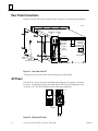
Rear Panel Connections . . . . . . . . . . . . . . . . . . . . . . . . . . . . . . . . . . . . . . . . . . .
AC Power . . . . . . . . . . . . . . . . . . . . . . . . . . . . . . . . . . . . . . . . . . . . . . . . . . . . . . . .
Battery Replacement . . . . . . . . . . . . . . . . . . . . . . . . . . . . . . . . . . . . . . . . . . . . . .
Communication Interface . . . . . . . . . . . . . . . . . . . . . . . . . . . . . . . . . . . . . . . . . .
Port Connector Definitions . . . . . . . . . . . . . . . . . . . . . . . . . . . . . . . . . . . . . . . . .
General Information about Handshaking . . . . . . . . . . . . . . . . . . . . . . . . . . . .
Handshaking with RS-232C Signals . . . . . . . . . . . . . . . . . . . . . . . . . . . . . . . . .
Handshaking with RS-422 Signals . . . . . . . . . . . . . . . . . . . . . . . . . . . . . . . . . . .
Cable and Connector Specifications . . . . . . . . . . . . . . . . . . . . . . . . . . . . . . . . .
Typical Cable Wiring Configurations . . . . . . . . . . . . . . . . . . . . . . . . . . . . . . . . .
Multidrop Operations . . . . . . . . . . . . . . . . . . . . . . . . . . . . . . . . . . . . . . . . . . . . .
Configuring the OIT . . . . . . . . . . . . . . . . . . . . . . . . . . . . . . . . . . . . . . . . . . .
Wiring for RS-422 Communications . . . . . . . . . . . . . . . . . . . . . . . . . . . . . .
RS-422 Communication with Pull-Up Resistors . . . . . . . . . . . . . . . . . . . . .
How Multidrop Operation Works . . . . . . . . . . . . . . . . . . . . . . . . . . . . . . . .
Setting the Configuration Switches . . . . . . . . . . . . . . . . . . . . . . . . . . . . . . . . . .
Interpreting the Diagnostic Status Codes . . . . . . . . . . . . . . . . . . . . . . . . . . . . .
Logic Board Jumpers . . . . . . . . . . . . . . . . . . . . . . . . . . . . . . . . . . . . . . . . . . . . . .
Information About the Logic Board . . . . . . . . . . . . . . . . . . . . . . . . . . . . . . . . .
CRT Adjustment . . . . . . . . . . . . . . . . . . . . . . . . . . . . . . . . . . . . . . . . . . . . . . . . . .
3-1
3-2
3-2
3-3
3-4
3-5
3-6
3-7
3-7
3-8
3-8
3-11
3-11
3-12
3-16
3-16
3-17
3-20
3-22
3-25
3-25
Operation . . . . . . . . . . . . . . . . . . . . . . . . . . . . . . . . . . . . . . . . . . . . . . . . .
4-1
Turning the OIT On . . . . . . . . . . . . . . . . . . . . . . . . . . . . . . . . . . . . . . . . . . . . . . .
The Main Menu – The Main Function Bar . . . . . . . . . . . . . . . . . . . . . . . . . . .
The SETUP Menu – [F1] from the Main Function Bar . . . . . . . . . . . . . . . . . .
The Screen Menu – [F2] from the Main Function Bar . . . . . . . . . . . . . . . . . .
The Tools Menu – [F6] from the Main Function Bar . . . . . . . . . . . . . . . . . . .
The CONFIG Menu – [F7] from the Main Function Bar . . . . . . . . . . . . . . . .
Configuration Procedure . . . . . . . . . . . . . . . . . . . . . . . . . . . . . . . . . . . . . . . .
Configuration Options . . . . . . . . . . . . . . . . . . . . . . . . . . . . . . . . . . . . . . . . .
ONLINE Mode – [F8] from the Main Function Bar . . . . . . . . . . . . . . . . . . . .
LOCAL Mode – [F9] from the Main Function Bar . . . . . . . . . . . . . . . . . . . . .
RUN – [F10] from the Main Function Bar . . . . . . . . . . . . . . . . . . . . . . . . . . . .
Placing a User Application in ROM . . . . . . . . . . . . . . . . . . . . . . . . . . . . . . . . . .
Storing an Application in EPROM Chips . . . . . . . . . . . . . . . . . . . . . . . . . .
Supplying File Protection and Security . . . . . . . . . . . . . . . . . . . . . . . . . . . . . . .
Keyboard Operation . . . . . . . . . . . . . . . . . . . . . . . . . . . . . . . . . . . . . . . . . . . . . .
Alphabetic Keys . . . . . . . . . . . . . . . . . . . . . . . . . . . . . . . . . . . . . . . . . . . . . . .
Nonalphabetic Keys . . . . . . . . . . . . . . . . . . . . . . . . . . . . . . . . . . . . . . . . . . . .
Cursor Keys . . . . . . . . . . . . . . . . . . . . . . . . . . . . . . . . . . . . . . . . . . . . . . . . . . .
Function Keys . . . . . . . . . . . . . . . . . . . . . . . . . . . . . . . . . . . . . . . . . . . . . . . . .
Miscellaneous Keys . . . . . . . . . . . . . . . . . . . . . . . . . . . . . . . . . . . . . . . . . . . .
Control Keys . . . . . . . . . . . . . . . . . . . . . . . . . . . . . . . . . . . . . . . . . . . . . . . . . .
4-2
4-3
4-4
4-4
4-6
4-14
4-15
4-15
4-24
4-24
4-24
4-24
4-25
4-26
4-27
4-27
4-28
4-28
4-28
4-29
4-29
GFK–0872
OperatorInterface Terminal User’s Manual - March 1994
vi
Contents
Chapter 5
Chapter 6
OptiSCREEN Statement Reference . . . . . . . . . . . . . . . . . . . . . . . . . . .
5-1
OptiSCREEN Statement Types . . . . . . . . . . . . . . . . . . . . . . . . . . . . . . . . . . . . .
Conventions for the OptiSCREEN Statements . . . . . . . . . . . . . . . . . . . . . . . .
The Comment and End of File Statements . . . . . . . . . . . . . . . . . . . . . . . . . . . .
Configuration Statements . . . . . . . . . . . . . . . . . . . . . . . . . . . . . . . . . . . . . . . . . .
Cursor Statements . . . . . . . . . . . . . . . . . . . . . . . . . . . . . . . . . . . . . . . . . . . . . . . .
Controlling the Appearance of the Cursor . . . . . . . . . . . . . . . . . . . . . . . . .
Controlling the Location of the Cursor . . . . . . . . . . . . . . . . . . . . . . . . . . . .
Character Attribute Statements . . . . . . . . . . . . . . . . . . . . . . . . . . . . . . . . . . . . .
Attributes for Both Color and Monochrome OITs . . . . . . . . . . . . . . . . . . .
Comparison of Various Character Attribute Modes . . . . . . . . . . . . . . . . .
Attributes for OITs in Color Mode Only . . . . . . . . . . . . . . . . . . . . . . . . . . .
Attributes for OITs in Monochrome Mode Only . . . . . . . . . . . . . . . . . . . .
The ATTRIBUTE Statement . . . . . . . . . . . . . . . . . . . . . . . . . . . . . . . . . . . . .
Line Attribute Statements . . . . . . . . . . . . . . . . . . . . . . . . . . . . . . . . . . . . . . . . . .
Clock and Date Statements . . . . . . . . . . . . . . . . . . . . . . . . . . . . . . . . . . . . . . . . .
Display Statements . . . . . . . . . . . . . . . . . . . . . . . . . . . . . . . . . . . . . . . . . . . . . . .
File Display Statement . . . . . . . . . . . . . . . . . . . . . . . . . . . . . . . . . . . . . . . . . . . . .
Erasing and Editing Statements . . . . . . . . . . . . . . . . . . . . . . . . . . . . . . . . . . . . .
Clearing the Screen . . . . . . . . . . . . . . . . . . . . . . . . . . . . . . . . . . . . . . . . . . . .
Inserting Text . . . . . . . . . . . . . . . . . . . . . . . . . . . . . . . . . . . . . . . . . . . . . . . . . .
Scrolling . . . . . . . . . . . . . . . . . . . . . . . . . . . . . . . . . . . . . . . . . . . . . . . . . . . . . .
Graphics Statements . . . . . . . . . . . . . . . . . . . . . . . . . . . . . . . . . . . . . . . . . . . . . .
Generating Boxes and Boxed Regions . . . . . . . . . . . . . . . . . . . . . . . . . . . . .
Drawing Bar Graphs . . . . . . . . . . . . . . . . . . . . . . . . . . . . . . . . . . . . . . . . . . .
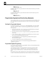
Programmable Keyboard and Function Key Statements . . . . . . . . . . . . . . . .
Selecting the Programmable Keyboard . . . . . . . . . . . . . . . . . . . . . . . . . . . .
Programmable Keyboard Programming . . . . . . . . . . . . . . . . . . . . . . . . . . .
Data Transmissions and Port Control Statements . . . . . . . . . . . . . . . . . . . . . .
Data Fill Operations . . . . . . . . . . . . . . . . . . . . . . . . . . . . . . . . . . . . . . . . . . . .
Statement Summary . . . . . . . . . . . . . . . . . . . . . . . . . . . . . . . . . . . . . . . . . . . . . .
5-1
5-2
5-3
5-3
5-4
5-5
5-5
5-8
5-9
5-12
5-14
5-15
5-19
5-20
5-22
5-22
5-24
5-24
5-25
5-29
5-30
5-32
5-32
5-36
5-40
5-40
5-40
5-43
5-44
5-46
Utility Programs for the IBM PC . . . . . . . . . . . . . . . . . . . . . . . . . . . . .
6-1
Installing the OptiTALK Utility . . . . . . . . . . . . . . . . . . . . . . . . . . . . . . . . . . . . .
Using the OptiTALK Utility . . . . . . . . . . . . . . . . . . . . . . . . . . . . . . . . . . . . . . . .
File Names and Extensions . . . . . . . . . . . . . . . . . . . . . . . . . . . . . . . . . . . . . . . . .
Hardware/Software Compatibility With
GE Fanuc
IC600KD510/512/530/532 . . . . . . . . . . . . . . . . . . . . . . . . . . . . . . . .
Transferring Files to This OIT . . . . . . . . . . . . . . . . . . . . . . . . . . . . . . . . . . . . . . .
Transferring Files from a Firmware Release Before Release 2.2 . . . . . . . . . .
Transferring Files from Firmware Release 2.2 through
Release 2.4 . . . . . . . . . . . . . . . . . . . . . . . . . . . . . . . . . . . . . . . . . . . . . . . . . . . . .
Transferring Files from Firmware Release 3.1 through
Release 4.0 . . . . . . . . . . . . . . . . . . . . . . . . . . . . . . . . . . . . . . . . . . . . . . . . . . . . .
Transferring Files from Firmware Release 4.1 . . . . . . . . . . . . . . . . . . . . . . . . .
6-1
6-1
6-10
GFK–0872
OperatorInterface Terminal User’s Manual - March 1994
vii
6-11
6-11
6-13
6-13
6-14
6-14
Contents
Appendix A
Outline and Mounting Drawings . . . . . . . . . . . . . . . . . . . . . . . . . . . .
A-1
Appendix B
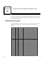
ASCII Codes and Special Character Sets . . . . . . . . . . . . . . . . . . . . . .
B-1
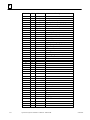
ASCII Codes and Characters . . . . . . . . . . . . . . . . . . . . . . . . . . . . . . . . . . . . . . .
B-1
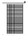
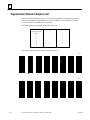
Supplemental Standard Graphics Set . . . . . . . . . . . . . . . . . . . . . . . . . . . . . . . .
B-6
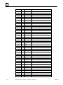
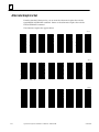
Alternate Graphics Set . . . . . . . . . . . . . . . . . . . . . . . . . . . . . . . . . . . . . . . . . . . . .
B-8
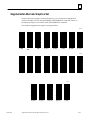
Supplemental Alternate Graphics Set . . . . . . . . . . . . . . . . . . . . . . . . . . . . . . . .
B-11
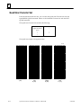
Quad Size Character Set . . . . . . . . . . . . . . . . . . . . . . . . . . . . . . . . . . . . . . . . . . .
B-12
Appendix C
Screen Programming Template . . . . . . . . . . . . . . . . . . . . . . . . . . . . . .
C-1
Appendix D
ANSI Escape Sequences for PLCs . . . . . . . . . . . . . . . . . . . . . . . . . . . .
D-1
Appendix E
VT52 Escape Sequences . . . . . . . . . . . . . . . . . . . . . . . . . . . . . . . . . . . .
E-1
Appendix F
Function Key Operations . . . . . . . . . . . . . . . . . . . . . . . . . . . . . . . . . . . .
F-1
Summary of the Manual . . . . . . . . . . . . . . . . . . . . . . . . . . . . . . . . . . . . . . . . . . .
iii
Related Publications . . . . . . . . . . . . . . . . . . . . . . . . . . . . . . . . . . . . . . . . . . . . . .
iii
GFK–0872
OperatorInterface Terminal User’s Manual - March 1994
viii
Contents
Figure 1-1. The OIT - Front and Side Views . . . . . . . . . . . . . . . . . . . . . . . . . . . . . . . . . . . . . . . . . . . . . . . .
1-2
Figure 1-2. Typical Screen Format Created Using the OptiSCREEN Editor . . . . . . . . . . . . . . . . . . . . . .
1-5
Figure 1-3. Connecting the OIT to a Series 90-70 or Series 90-30 PCM Module . . . . . . . . . . . . . . . . . .
1-6
Figure 1-4. Connecting the OIT to a Series Six ASCII/BASIC Module . . . . . . . . . . . . . . . . . . . . . . . . . . .
1-6
Figure 1-5. The 35-Position Integral Keyboard . . . . . . . . . . . . . . . . . . . . . . . . . . . . . . . . . . . . . . . . . . . . . .
1-7
Figure 1-6. Dimensions for Function Key Legends . . . . . . . . . . . . . . . . . . . . . . . . . . . . . . . . . . . . . . . . . .
1-8
Figure 2-1. Wiring Diagram for AC Power . . . . . . . . . . . . . . . . . . . . . . . . . . . . . . . . . . . . . . . . . . . . . . . . .
2-2
Figure 2-2. Sample Screen Format . . . . . . . . . . . . . . . . . . . . . . . . . . . . . . . . . . . . . . . . . . . . . . . . . . . . . . . .
2-17
Figure 3-1. Rear View of the OIT . . . . . . . . . . . . . . . . . . . . . . . . . . . . . . . . . . . . . . . . . . . . . . . . . . . . . . . . .
3-2
Figure 3-2. Wiring for AC Power . . . . . . . . . . . . . . . . . . . . . . . . . . . . . . . . . . . . . . . . . . . . . . . . . . . . . . . . . .
3-2
Figure 3-3. Battery Assembly . . . . . . . . . . . . . . . . . . . . . . . . . . . . . . . . . . . . . . . . . . . . . . . . . . . . . . . . . . . .
3-3
Figure 3-4. Connecting the Battery . . . . . . . . . . . . . . . . . . . . . . . . . . . . . . . . . . . . . . . . . . . . . . . . . . . . . . .
3-4
Figure 3-5. Primary and Secondary Port Using DB-25P Male Connector . . . . . . . . . . . . . . . . . . . . . . . .
3-5
Figure 3-6. RS-232C Point-to-Point Communication with Handshaking
(OIT Serial Port to Series Six ASCII/BASIC Module Port 1 or Port 2) . . . . . . . . .
3-9
Figure 3-7. RS-232C Point-to-Point Communication, No Handshaking
(OIT Serial Port to Series Six ASCII/BASIC Module Port 1 or Port 2) . . . . . . . . .
3-9
Figure 3-8. RS-232C Point-to-Point Communication (OIT Serial Port to Printer on
STR-LINK III) . . . . . . . . . . . . . . . . . . . . . . . . . . . . . . . . . . . . . . . . . . . . . . . . . . . . . .
3-9
Figure 3-9. RS-422 Point-to-Point Communication
(OIT Serial Port to Series Six ASCII/BASIC Module Port 1 or Port 2) . . . . . . . . .
3-9
Figure 3-10. RS-232 Point-to-Point Communication with Handshaking
(OIT Serial Port to Series 90-70 PCM Module Port 1 or Port 2) . . . . . . . . . . . . .
3-10
Figure 3-11. RS-422 Point-to-Point Communication with Handshaking
(OIT Serial Port to Series 90-70 PCM Module Port 1 or Port 2) . . . . . . . . . . . . .
3-10
Figure 3-12. RS-232 Point-to-Point Communication with Handshaking
(OIT Serial Port to Series 90-30 PCM Module Port 1) . . . . . . . . . . . . . . . . . . . .
3-10
Figure 3-13. RS-422 Point-to-Point Communication
(OIT Serial Port to Series 90-30 PCM Module Port 2) . . . . . . . . . . . . . . . . . . . .
3-11
Figure 3-14. RS-422 Multidrop 2-Wire (OIT Serial Port to Series Six ASCII/BASIC Module) . . . . . . . .
3-13
Figure 3-15. RS-422 Multidrop 4-Wire (OIT Serial Port to Series 90-70 PCM
Module Port 1 or Port 2) . . . . . . . . . . . . . . . . . . . . . . . . . . . . . . . . . . . . . . . . . . . .
3-14
Figure 3-16. RS-422 Multidrop 4-Wire (OIT Serial Port or Secondary Port to
Series 90-30 PCM Module Port 2) . . . . . . . . . . . . . . . . . . . . . . . . . . . . . . . . . . . .
3-15
Figure 3-17. RS-422 Communication with Pull-Up Resistors . . . . . . . . . . . . . . . . . . . . . . . . . . . . . . . . . .
3-16
Figure 3-18. Default Switch Settings for the OIT . . . . . . . . . . . . . . . . . . . . . . . . . . . . . . . . . . . . . . . . . . . .
3-18
Figure 3-19. Logic Board-Memory Chip Location . . . . . . . . . . . . . . . . . . . . . . . . . . . . . . . . . . . . . . . . . . .
3-22
Figure 5-1. Key Location Numbers for the 35-Position Built-In Keyboard . . . . . . . . . . . . . . . . . . . . . . .
5-42
Figure 6-1. OIT Serial Port to IBM XT-Compatible Computer . . . . . . . . . . . . . . . . . . . . . . . . . . . . . . . . .
6-2
Figure 6-2. OIT Serial Port to IBM AT-Compatible Computer . . . . . . . . . . . . . . . . . . . . . . . . . . . . . . . . .
6-2
Figure A-1. Outline Drawing for OIT Models IC600KD542 . . . . . . . . . . . . . . . . . . . . . . . . . . . . . . . . . . .
A-1
Figure A-2. Cutout Drawing for OIT Models IC600KD542 . . . . . . . . . . . . . . . . . . . . . . . . . . . . . . . . . . . .
A-2
GFK–0872
OperatorInterface Terminal User’s Manual - March 1994
ix
Contents
Table 1-1. Feature Comparison Between OIT Models . . . . . . . . . . . . . . . . . . . . . . . . . . . . . . . . . . . . . . . .
1-3
Table D-1. Escape Sequence OptiSCREEN Command . . . . . . . . . . . . . . . . . . . . . . . . . . . . . . . . . . . . . . .
D-2
GFK–0872
OperatorInterface Terminal User’s Manual - March 1994
x
restart lowapp
restart ARestart
lowapp ARestart
oddapp:oddapp:
ARestarts
ARestarts
for autonumbers
for autonumbers
that do not
thatrestart
do notinrestart in
each chapter.
each chapter.
figure bifigure
level 1,
bireset
level table_big
1, reset table_big
level 1, reset
level chap_big
1, reset chap_big
level 1, reset1
level 1, reset1
LowappLowapp
Alwbox Alwbox
restart evenap:A1app_big
restart evenap:A1app_big
level 1, resetA
level 1,figure_ap
resetA figure_ap
level 1, reset
level 1, reset
levelfigure
1, reset
figure
level table
1, reset
table
level 1,
resetrestarts
these restarts
table_aptable_ap
level 1, reset
level
1, reset
level
1, reset
these
oddbox oddbox
reset: 1evenbox
reset: 1evenbox
reset: 1must
reset:be1must
in thebe
header
in theframe
header
offrame
chapter
of 1.
chapter
a:ebx, 1.
l 1a:ebx, l 1
resetA a:obx:l
resetA1,a:obx:l
resetA1,a:bigbx
resetAlevel
a:bigbx
1 resetA
level 1a:ftr
resetA
level
a:ftr
1 resetA
level 1c:ebx,
resetA
l 1c:ebx,
reset1l 1 reset1
c:obx:l 1,c:obx:l
reset11,
c:bigbx
reset1 c:bigbx
level 1 reset1
level c:ftr
1 reset1
level
c:ftr
1 reset1
level 1Reminders
reset1 Reminders
for
for
autonumbers
autonumbers
that needthat
to be
need
restarted
to be restarted
manually
manually
(first instance
(first instance
will always
willbe
always
4)
be 4)
let_in level
let_in
1: A.
level
B. C.
1: A.
letter
B. C.
level
letter
1:A.B.C.
level 1:A.B.C.
num level
num
1: 1.level
2. 3.1:num_in
1. 2. 3. num_in
level 1: 1.level
2. 1: 1. 2.
3. rom_in
3. level
rom_in
1: I.level
II. III.
1: roman
I. II. III.level
roman
1: I.level
II. III.
1: I.
steps
II. III.
level
steps
1: 1.level
2. 3.1: 1. 2. 3.
Chapter
1 Introduction
1
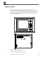
The Operator Interface Terminal (OIT) is a rugged, intelligent terminal specifically built
for use in harsh environments. The sealed front panel of the OIT complies with NEMA 4
and NEMA 12 specifications and includes a shatterproof window. It is typically used as
an operator control and monitoring station for industrial machines that are capable of
communicating over a serial interface. These industrial machines may be host
computers, CNC systems, programmable logic controllers, robots, and other
computer-based data acquisition, monitoring, and control systems. In this manual,
however, the intelligent machine described will usually be a Programmable Logic
Controller (PLC) such as the Series 90t-70, Series 90-30, Series Fivet, or Series Sixt
PLC from GE Fanuc Automation.
The Operator Interface Terminal (OIT) is available in several models.
IC600KD542 Standard Color OIT
IC600KD515* Mini OIT
IC600KD516* Mini OIT with Touchscreen
* The Mini OIT is not described in this manual. For more information refer to the
table in this chapter comparing OIT models. Also, refer to the Mini OIT User’s
Manual,
GFK-0361.
Note
There are options for OITs which are supplied by the original
manufacturer, but not stocked or sold by GE Fanuc Automation. For
additional information, contact GE Fanuc Automation Customer Service.
This chapter provides an overview of the OIT. The topics covered are:
H
H
H
H
H
H
GFK-0872
Features of the OIT
Feature Comparison of GE Fanuc OIT Models
General System Operation
Keyboards for the OIT
Specifications
OIT Compatibility
1-1
1
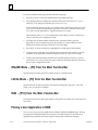
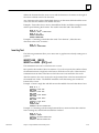
Features of the OIT
The OIT is an intelligent terminal that stores screen files generated by the
OptiSCREEN utility. The OIT is built to NEMA 4 and NEMA 12 specifications making
it ideal for factory floor applications. The OIT operates using either the ANSI X3.64, the
VT-100, or the VT-52 escape sequences. This means the OIT can replace many terminals
which also use these escape sequences such as the DEC VT-100 and VT-220. See the
illustration of the OIT below.
t
a45273
HOME
7
8
9
4
5
6
1
2
3
0
–
BACK
SPACE
ENTER
F11 F12 F13
F1
F2
F3
F4
F5
F6
F7
F8
F9
F10
F14 F15 F16
Î
Î
ÎÎ
ÎÎ Î
Î
Î
Î
Î
Î
Î
Î
Î
ÎÎ
ÎÎ
Figure 1-1. The OIT - Front and Side Views
tOptiSCREENis a trademark of NematronCorporation.
1-2
Operator Interface Terminal User’s Manual - March 1994
GFK-0872
1
Other important features of the OIT are described below.
H
OptiSCREEN Editor: The OptiSCREEN Editor allows you to easily create and store
screens which are used to display data from the PLC or host. English language
commands are used instead of escape sequences.
H
Serial Interfaces: The serial ports are typically used to connect to a host such as a
PLC and to a printer. There are two serial ports on the OIT referred to as the
Primary port and the Secondary port. Both ports have RS-232C, RS-422, and RS-485
capabilities and both are optically isolated.
H
OIT Memory: The OIT is shipped with 128 Kbytes RAM (64 Kbytes for system use
and 64 Kbytes for user screen files) and are expandable to 256 Kbytes RAM.
H
Menu-Driven Software: The menu-driven software allows you to easily access the
OIT functions: OptiSCREEN editor, system configuration, and file and screen
transfers.
H
Keyboards: During programming, an IBM-compatible, full-travel, QWERTY
keyboard will be required. A round DIN keyboard connector is provided at the rear
of the unit. Either an IBM XT- or AT-compatible keyboard may be used. GE Fanuc
offers such a keyboard as part number IC642PKB250.
H
Clock and Calendar Display: A battery-backed clock and calendar display the time
and date at the bottom of the screen if desired. The clock and calendar can be reset
from either the keyboard or through external commands. Moreover, the time and
date can be used for time and date stamping of all OIT functions.
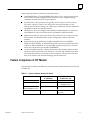
Feature Comparison of OIT Models
The table below explains the differences in features between the full-sized color OIT and
the Mini OIT.
ÁÁÁÁÁÁÁÁ
ÁÁÁÁÁÁÁÁÁ
ÁÁÁÁÁÁÁÁ
ÁÁÁÁÁÁÁÁ
ÁÁÁÁÁÁÁÁÁ
ÁÁÁÁÁÁÁÁ
ÁÁÁÁÁÁÁÁ
ÁÁÁÁÁÁÁÁÁ
ÁÁÁÁÁÁÁÁ
ÁÁÁÁÁÁÁÁ
ÁÁÁÁÁÁÁÁÁ
ÁÁÁÁÁÁÁÁ
ÁÁÁÁÁÁÁÁ
ÁÁÁÁÁÁÁÁÁ
ÁÁÁÁÁÁÁÁ
ÁÁÁÁÁÁÁÁ
ÁÁÁÁÁÁÁÁÁ
ÁÁÁÁÁÁÁÁ
ÁÁÁÁÁÁÁÁ
ÁÁÁÁÁÁÁÁÁ
ÁÁÁÁÁÁÁÁ
ÁÁÁÁÁÁÁÁ
ÁÁÁÁÁÁÁÁÁ
ÁÁÁÁÁÁÁÁ
ÁÁÁÁÁÁÁÁ
ÁÁÁÁÁÁÁÁÁ
ÁÁÁÁÁÁÁÁ
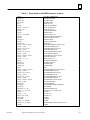
Table 1-1. Feature Comparison Between OIT Models
Feature
Full Size Color
IC600KD542
Mini OIT
IC600KD515, 516
OptiSCREENEditing
Yes
Yes
Touch Screen CRT
No
Yes
IC600KD516 only
KeyboardsAvailable
35-position built in
65-position full ASCII
2 serial
1 serial
1 parallel
(Sealed Membrane type)
Ports
GFK-0872
Chapter 1 Introduction
1-3
1
Table 1-1. Feature Comparison Between OIT Models - Continued
ÁÁÁÁÁÁÁÁ
ÁÁÁÁÁÁÁÁÁ
ÁÁÁÁÁÁÁÁ
ÁÁÁÁÁÁÁÁ
ÁÁÁÁÁÁÁÁÁ
ÁÁÁÁÁÁÁÁ
ÁÁÁÁÁÁÁÁ
ÁÁÁÁÁÁÁÁÁ
ÁÁÁÁÁÁÁÁ
ÁÁÁÁÁÁÁÁ
ÁÁÁÁÁÁÁÁÁ
ÁÁÁÁÁÁÁÁ
ÁÁÁÁÁÁÁÁ
ÁÁÁÁÁÁÁÁÁ
ÁÁÁÁÁÁÁÁ
ÁÁÁÁÁÁÁÁÁ
ÁÁÁÁÁÁÁÁ
ÁÁÁÁÁÁÁÁ
ÁÁÁÁÁÁÁÁ
ÁÁÁÁÁÁÁÁÁ
ÁÁÁÁÁÁÁÁ
ÁÁÁÁÁÁÁÁ
ÁÁÁÁÁÁÁÁÁ
ÁÁÁÁÁÁÁÁ
ÁÁÁÁÁÁÁÁ
ÁÁÁÁÁÁÁÁÁ
ÁÁÁÁÁÁÁÁ
ÁÁÁÁÁÁÁÁ
ÁÁÁÁÁÁÁÁÁ
ÁÁÁÁÁÁÁÁ
ÁÁÁÁÁÁÁÁ
ÁÁÁÁÁÁÁÁÁ
ÁÁÁÁÁÁÁÁ
ÁÁÁÁÁÁÁÁ
ÁÁÁÁÁÁÁÁÁ
ÁÁÁÁÁÁÁÁ
ÁÁÁÁÁÁÁÁ
ÁÁÁÁÁÁÁÁÁ
ÁÁÁÁÁÁÁÁ
ÁÁÁÁÁÁÁÁ
ÁÁÁÁÁÁÁÁÁ
ÁÁÁÁÁÁÁÁ
ÁÁÁÁÁÁÁÁ
ÁÁÁÁÁÁÁÁÁ
ÁÁÁÁÁÁÁÁ
ÁÁÁÁÁÁÁÁ
ÁÁÁÁÁÁÁÁÁ
ÁÁÁÁÁÁÁÁ
Feature
User Memory
Full Size Color
IC600KD512, 514
128 Kbytes shipped (64
Kbytes user)
256 Kbytes total
Mini OIT
IC600KD515, 516
IC600KD515,
IC600KD516 30 Kbytes shipped
62 Kbytes total
Character Sets
95 ASCII, 161 Graphic,
80 Quad Size letters,
numbers,symbols
95 ASCII, 33 Graphic from
Stand. char. set. No Alternate character set or Quad
size process symbols
IBM Keyboard Connector
Types
DIN type only for full-size
IBM PC-XT or AT.
DIN type only for full size
IBM PC-XT or AT
Color CRT
Screen Size
Yes
14”diag.
25 or 30 lines,
80 or 132 char. per line
No
5” x 9”,
16 lines,
80 char. per line
Status Lines
0-7
None
Battery Backed Clock and
Calendar
Yes
No
General Operation of the OIT
The OIT is designed to receive dynamic (changing) data from the host computer (PLC)
and display it on the screen in a user-programmed screen format. This format is created
using the OptiSCREEN Editor and typically does not change as often as the dynamic
information from the PLC. The operator can enter data and initiate action to be taken by
the PLC by pressing keys on the keyboard.
The information displayed on the OIT is of two types.
H
H
Dynamic data such as counter or timer values from the PLC.
Screen format programmed using the OptiSCREEN Editor which makes the
dynamic information easy to read.
How the Dynamic Data is Produced
The origin of the dynamic data displayed on the OIT is the host or PLC. This data can be
raw data, but often it needs to be processed in some way before it is displayed.
1-4
Operator Interface Terminal User’s Manual - March 1994
GFK-0872
1
The Series 90-70 and Series 90-30 PCM modules can be used for processing raw data
through the modules’ resident BASIC. The ASCII/BASIC module provides the same
capability for the Series Six PLC. These modules also retrieve operator-entered data and
key presses to be acted upon by the PLC.
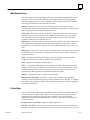
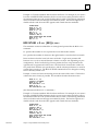
Creating the Screen Format
The OptiSCREEN Editor allows you to create screen formats easily, using
English-language commands instead of the cumbersome escape sequences required on
some terminals. The screen format usually consists of the screen title, explanations of
the dynamic data, and any graphics such as lines and boxes used to clearly present the
data.
The figure below illustrates a typical screen format.
a44147
AUTO–PLATER
SELECT FUNCTION
RUN TIME Today
Week
F1 Hoist Control
F2 Rectifier Control
FAULTS
Today
Week
Figure 1-2. Typical Screen Format Created Using the OptiSCREEN Editor
GFK-0872
Chapter 1 Introduction
1-5
1
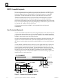
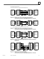
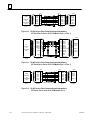
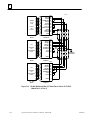
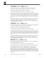
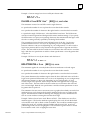
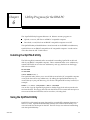
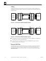
Transferring Data Between the Host (PLC) and the OIT
The serial ports include an RS-232, an RS-422, or an RS-485 interface which can be
connected to an intelligent module such as the Series 90-70 or Series 90-30 PCM module
or a Series Five or Series Six ASCII/BASIC or CCM module.
The figures below show the connections for a serial configuration using the OIT.
ÎÎÎÎÎÎÎÎÎÎÎÎ
ÎÎÎÎÎÎÎÎÎÎ
ÎÎÎÎÎÎ
ÎÎÎÎÎÎÎÎÎÎÎÎ
ÎÎÎÎÎÎÎÎÎÎÎÎ
ÎÎÎÎÎÎÎÎÎÎ
ÎÎÎÎÎÎ
ÎÎÎÎÎÎÎÎÎÎÎÎ
ÎÎÎÎÎÎÎÎÎÎ
ÎÎÎÎÎÎ
ÎÎÎÎÎÎÎÎÎÎÎÎ
ÎÎÎÎÎÎÎÎÎÎ
ÎÎÎÎÎÎ
Î
ÎÎÎÎÎÎ
ÎÎÎÎÎÎÎÎÎÎÎÎ
ÎÎÎÎÎÎÎÎÎÎ
Î
ÎÎÎÎÎÎÎÎÎÎÎÎ
ÎÎÎÎÎÎÎÎÎÎ
ÎÎÎÎÎÎ
ÎÎÎÎÎÎÎÎÎÎÎÎ
ÎÎÎÎÎÎÎÎÎÎ
ÎÎÎÎÎÎÎÎÎÎÎÎ
ÎÎÎÎÎÎÎÎÎÎÎ
ÎÎÎÎÎÎÎÎÎÎÎ
ÎÎÎÎÎÎÎÎÎÎÎ
a45278
SERIES 90–70 PLC
KEYBOARD
Î
Î
P
OIT
C
M
SERIAL CABLE
Figure 1-3. Connecting the OIT to a Series 90-70 or Series 90-30 PCM Module
ÎÎÎÎÎÎÎÎÎÎÎÎ
ÎÎÎÎÎÎÎÎÎÎ
ÎÎÎÎÎÎÎÎÎÎÎÎ
ÎÎÎÎÎÎÎÎÎÎ
ÎÎÎÎÎÎ
ÎÎÎÎÎÎÎÎÎÎÎÎ
ÎÎÎÎÎÎÎÎÎÎ
ÎÎÎÎÎÎ
ÎÎÎÎÎÎÎÎÎÎÎÎ
ÎÎÎÎÎÎÎÎÎÎ
ÎÎÎÎÎÎ
ÎÎÎÎÎÎÎÎÎÎÎÎ
ÎÎÎÎÎÎÎÎÎÎ
ÎÎÎÎÎÎ
ÎÎÎÎÎÎÎÎÎÎÎÎ
ÎÎÎÎÎÎÎÎÎÎ
ÎÎÎÎÎÎ
ÎÎÎÎÎÎÎÎÎÎÎÎ
ÎÎÎÎÎÎÎÎÎÎ
ÎÎÎÎÎÎ
ÎÎÎÎÎÎÎÎÎÎÎÎ
ÎÎÎÎÎÎÎÎÎÎÎ
ÎÎÎÎÎÎÎÎÎÎÎ
ÎÎÎÎÎÎÎÎÎÎÎ
a45279
SERIES SIX PLUS PLC
A
B
M
SERIAL CABLE
KEYBOARD
Figure 1-4. Connecting the OIT to a Series Six ASCII/BASIC Module
1-6
Operator Interface Terminal User’s Manual - March 1994
GFK-0872
1
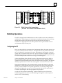
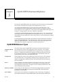
Keyboards for the OIT
The OIT comes with an integral 35-position sealed-membrane keyboard. This built-in
keyboard is sufficient to perform most operator functions. However, for system
configuration and screen development, you will need to use either a standard IBM
PC-XT or AT keyboard.
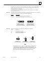
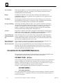
35-P osition Keyboard
The OIT’s built-in keyboard features a numeric keypad, cursor control pad, and 16
function keys. The function key legends are also printed on slide-in inserts for easy user
customization.
You can define the function keys to represent up to 16 ASCII characters (including
escape sequences) for on-line operation.
a45280
HOME
7
8
9
4
5
6
1
2
3
0
–
BACK
SPACE
ENTER
F11 F12 F13
F1
F2
F3
F4
F5
F6
F7
F8
F9
F10
F14 F15 F16
Figure 1-5. The 35-Position Integral Keyboard
GFK-0872
Chapter 1 Introduction
1-7
1
IBM PC-Compatible Keyboards
During screen programming, and for certain permanent applications, an IBM PC-AT or
PC-XT-compatible full-travel QWERTY keyboard may be desirable. The OIT supports
keyboards designed for use with the IBM-PC-AT Personal Computer or compatible
equivalents. A round DIN keyboard connector is provided at the rear of the unit.
An IBM-compatible keyboard may be connected and used simultaneously with the
35-position integral keyboard. Not all of the special keys on the IBM-compatible
keyboard are appropriate for the OIT. The OIT supports IBM functions keys F1 through
F10; you can use the [Shift]-[F1] through [Shift]-[F6] key combinations to produce F11 to
F16; and the OIT supports the Print Screen key.
GE Fanuc Automation offers an IBM PC-AT-compatible full-travel keyboard;
IC642PKB250.
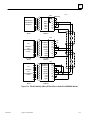
User-Customized Keyboards
You can custom label the functions keys in the integral keyboard. Each function key has
a clear window through which you can view the key legend. The standard legends are
preprinted on inserts of .005” thick mylar film and installed in slots located immediately
behind the front panel at each side of the enclosure.
To remove the standard legends locate the plastic tabs at the side of the enclosure. The
legends are sandwiched between the plastic tab marked INSERT and the clear plastic
tab. Remove only the legend (not the tab marked INSERT or the clear tab) by sliding it
out.
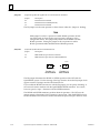
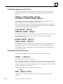
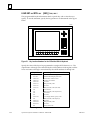
You can label the keyboard inserts to meet your specific application needs. Inserts may
be manufactured of any material and any color, but should be about 0.005” thick for
proper insertion and keyboard operation. The standard inserts can be used as a guide
for the proper size or you may refer to the figure below for the correct dimensions. Any
keys that you do not use may be left blank or printed black to match the keyboard
overlay foreground colors. All inserts should have a clear surface coating to protect the
legends during use on the plant floor.
a45354
F1–F10 INSERT
ÎÎ
ÎÎ
ÎÎ
ÎÎ
12.50 (317.51)
F1
F2
F11–F16 INSERT
5.00 (127.0)
F11
F12
F13
F14
F15
F16
Î
Î
.600 (15.24)
.750 (19.05)
.750 (19.05)
F3
F4
F5
F6
F7
F8
.031 RADIUS
F9
Î
Î
.031 RADIUS
F10
.130 (3.30)
.710 (18.03)
.150 (3.81)
.955 (24.26)
Typical
Non–Accum.
.130 (3.30)
.750 (19.05)
1.460 (37.08)
Figure 1-6. Dimensions for Function Key Legends
1-8
Operator Interface Terminal User’s Manual - March 1994
GFK-0872
1
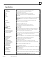
Specifications
ÁÁÁÁÁÁÁÁÁÁÁÁ
ÁÁÁÁÁÁÁÁÁÁÁÁÁÁÁÁÁÁÁÁÁÁ
ÁÁÁÁÁÁÁÁÁÁÁÁ
ÁÁÁÁÁÁÁÁÁÁÁÁÁÁÁÁÁÁÁÁÁÁ
ÁÁÁÁÁÁÁÁÁÁÁÁ
ÁÁÁÁÁÁÁÁÁÁÁÁÁÁÁÁÁÁÁÁÁÁ
ÁÁÁÁÁÁÁÁÁÁÁÁ
ÁÁÁÁÁÁÁÁÁÁÁÁÁÁÁÁÁÁÁÁÁÁ
ÁÁÁÁÁÁÁÁÁÁÁÁ
ÁÁÁÁÁÁÁÁÁÁÁÁÁÁÁÁÁÁÁÁÁÁ
ÁÁÁÁÁÁÁÁÁÁÁÁ
ÁÁÁÁÁÁÁÁÁÁÁÁÁÁÁÁÁÁÁÁÁÁ
ÁÁÁÁÁÁÁÁÁÁÁÁ
ÁÁÁÁÁÁÁÁÁÁÁÁÁÁÁÁÁÁÁÁÁÁ
ÁÁÁÁÁÁÁÁÁÁÁÁ
ÁÁÁÁÁÁÁÁÁÁÁÁÁÁÁÁÁÁÁÁÁÁ
ÁÁÁÁÁÁÁÁÁÁÁÁ
ÁÁÁÁÁÁÁÁÁÁÁÁÁÁÁÁÁÁÁÁÁÁ
ÁÁÁÁÁÁÁÁÁÁÁÁ
ÁÁÁÁÁÁÁÁÁÁÁÁÁÁÁÁÁÁÁÁÁÁ
ÁÁÁÁÁÁÁÁÁÁÁÁ
ÁÁÁÁÁÁÁÁÁÁÁÁÁÁÁÁÁÁÁÁÁÁ
ÁÁÁÁÁÁÁÁÁÁÁÁ
ÁÁÁÁÁÁÁÁÁÁÁÁÁÁÁÁÁÁÁÁÁÁ
ÁÁÁÁÁÁÁÁÁÁÁÁ
ÁÁÁÁÁÁÁÁÁÁÁÁÁÁÁÁÁÁÁÁÁÁ
ÁÁÁÁÁÁÁÁÁÁÁÁ
ÁÁÁÁÁÁÁÁÁÁÁÁÁÁÁÁÁÁÁÁÁÁ
ÁÁÁÁÁÁÁÁÁÁÁÁ
ÁÁÁÁÁÁÁÁÁÁÁÁÁÁÁÁÁÁÁÁÁÁ
ÁÁÁÁÁÁÁÁÁÁÁÁ
ÁÁÁÁÁÁÁÁÁÁÁÁÁÁÁÁÁÁÁÁÁÁ
ÁÁÁÁÁÁÁÁÁÁÁÁ
ÁÁÁÁÁÁÁÁÁÁÁÁÁÁÁÁÁÁÁÁÁÁ
ÁÁÁÁÁÁÁÁÁÁÁÁ
ÁÁÁÁÁÁÁÁÁÁÁÁÁÁÁÁÁÁÁÁÁÁ
ÁÁÁÁÁÁÁÁÁÁÁÁÁÁÁÁÁÁÁÁÁÁ
ÁÁÁÁÁÁÁÁÁÁÁÁ
ÁÁÁÁÁÁÁÁÁÁÁÁ
ÁÁÁÁÁÁÁÁÁÁÁÁÁÁÁÁÁÁÁÁÁÁ
ÁÁÁÁÁÁÁÁÁÁÁÁ
ÁÁÁÁÁÁÁÁÁÁÁÁÁÁÁÁÁÁÁÁÁÁ
ÁÁÁÁÁÁÁÁÁÁÁÁÁÁÁÁÁÁÁÁÁÁ
ÁÁÁÁÁÁÁÁÁÁÁÁ
ÁÁÁÁÁÁÁÁÁÁÁÁ
ÁÁÁÁÁÁÁÁÁÁÁÁÁÁÁÁÁÁÁÁÁÁ
ÁÁÁÁÁÁÁÁÁÁÁÁÁÁÁÁÁÁÁÁÁÁ
ÁÁÁÁÁÁÁÁÁÁÁÁ
ÁÁÁÁÁÁÁÁÁÁÁÁ
ÁÁÁÁÁÁÁÁÁÁÁÁÁÁÁÁÁÁÁÁÁÁ
ÁÁÁÁÁÁÁÁÁÁÁÁ
ÁÁÁÁÁÁÁÁÁÁÁÁÁÁÁÁÁÁÁÁÁÁ
ÁÁÁÁÁÁÁÁÁÁÁÁ
ÁÁÁÁÁÁÁÁÁÁÁÁÁÁÁÁÁÁÁÁÁÁ
ÁÁÁÁÁÁÁÁÁÁÁÁ
ÁÁÁÁÁÁÁÁÁÁÁÁÁÁÁÁÁÁÁÁÁÁ
ÁÁÁÁÁÁÁÁÁÁÁÁ
ÁÁÁÁÁÁÁÁÁÁÁÁÁÁÁÁÁÁÁÁÁÁ
ÁÁÁÁÁÁÁÁÁÁÁÁ
ÁÁÁÁÁÁÁÁÁÁÁÁÁÁÁÁÁÁÁÁÁÁ
ÁÁÁÁÁÁÁÁÁÁÁÁ
ÁÁÁÁÁÁÁÁÁÁÁÁÁÁÁÁÁÁÁÁÁÁ
ÁÁÁÁÁÁÁÁÁÁÁÁ
ÁÁÁÁÁÁÁÁÁÁÁÁÁÁÁÁÁÁÁÁÁÁ
ÁÁÁÁÁÁÁÁÁÁÁÁ
ÁÁÁÁÁÁÁÁÁÁÁÁÁÁÁÁÁÁÁÁÁÁ
ÁÁÁÁÁÁÁÁÁÁÁÁ
ÁÁÁÁÁÁÁÁÁÁÁÁÁÁÁÁÁÁÁÁÁÁ
ÁÁÁÁÁÁÁÁÁÁÁÁ
ÁÁÁÁÁÁÁÁÁÁÁÁÁÁÁÁÁÁÁÁÁÁ
ÁÁÁÁÁÁÁÁÁÁÁÁ
ÁÁÁÁÁÁÁÁÁÁÁÁÁÁÁÁÁÁÁÁÁÁ
ÁÁÁÁÁÁÁÁÁÁÁÁ
ÁÁÁÁÁÁÁÁÁÁÁÁÁÁÁÁÁÁÁÁÁÁ
ÁÁÁÁÁÁÁÁÁÁÁÁ
ÁÁÁÁÁÁÁÁÁÁÁÁÁÁÁÁÁÁÁÁÁÁ
ÁÁÁÁÁÁÁÁÁÁÁÁ
ÁÁÁÁÁÁÁÁÁÁÁÁÁÁÁÁÁÁÁÁÁÁ
ÁÁÁÁÁÁÁÁÁÁÁÁ
ÁÁÁÁÁÁÁÁÁÁÁÁÁÁÁÁÁÁÁÁÁÁ
Z180
64 Kbytes to 192 Kbytes battery-backed CMOS RAM available.
Black, textured Polane-T polyurethane paint standard.
14” diagonal, high-resolution VGA
Proprietary Foster-Grant glare shield made of ADC material.
25 or 30 lines of 80 or 132 characters, 0 - 7 independent status lines
45 lb (20.4 Kg)
Processor
UserMemory
Front panel finish
Color
Window
Format
Weight
Characters
Set
256 characters consisting of 95 ASCII and 161 graphic characters plus 80 quad size
letters, numbers, symbols. ASCII characters can be displayed normal size,
double-wide, or
quad size.
5 x 7 dot matrix, except: 5 x 9 dot matrix for lowercase characters with
descenders, 8 x 10 dot matrix for graphics
Formation
Video Attributes
Size
Color
Cursor
Cursor addressing
Scrolling
Keyboards
35-position (Sealed)
14” diagonal: 7.5” high by 10.5” wide
Eight foreground and eight background colors, plus blink
None, and blinking or continuous in underline or block forms
Relative and direct
Full or split screen
Full Travel Keyboard, optional
Keys in L-shaped configuration around display including 16 function keys, 0
to 9 numeric keys, Enter], Backspace], four cursor control keys, and Home].
IBM PC-AT type compatible with round DIN connector.
(Stand-alone as IC642PKB250)
General information
OperatingEnvironment
Sealed front panel
Temperature
Humidity
Shock and vibration
Electrical noise immunity
Certification UL and CSA
Power Requirements
Communications
Primary port (DTE)
Secondary port (DTE)
Input buffers
Optical isolation
Menu-configurable
GFK-0872
The built-in snap action of the sealed-membrane keyboards generate tactile feedback for input. The surface of all of the keyboards is a matte, UV
hardcoatedpolyester.
The OIT accepts IBM PC-AT or -XT-compatible keyboards with a round DIN connector.
Meets NEMA 4 (indoor use only) and NEMA 12 specifications
0 to 50 degrees Celsius (32 to 122 degrees Fahrenheit)
5 to 95% RH, non-condensing
5 to 10 Hz, 0.20 inches peak-to-peak 10 to 200 Hz, 1G peak-to-peak
NEMA showering arc test ICS 2-230. Surge withstand capacity ANSI C37.90A
115 Vac to 230 Vac (wide ranging), 50/60 Hz, 110 W
Serial RS-232, RS-422., and RS-485
Handshaking by hardware (RTS/CTS) or software (XON/XOFF). Uses DB-25P
connector.
Same as for Primary port.
256 characters per port
Serial ports are protected by circuits which provide up to 1,000 volts of line isolation.
Independent control of both ports 300, 600, 1200, 2400, 4800, 9600, or 19200 baud
rate.
7 or 8 bit characters. 1 or 2 stop bits. Odd, even
or no parity. Command sets: ANSI X3.64, VT52, or subset of VT100.
Chapter 1 Introduction
1-9
1
OIT Compatibility
The OIT supports a wide variety of existing hardware and software configurations,
therefore it can replace many other terminals. The OIT is completely compatible with
the ANSI X3.64 and VT52 operating modes.
The OIT makes a number of non-ANSI commands available to allow its use in place of a
DEC VT100 terminal. A number of differences, however, exist between the OIT and a
VT100 terminal. The DEC VT220 series of terminals provide additional capabilities
beyond the DEC VT100. The OIT, however, remains compatible with the VT220
terminal. The VT220 offers support for additional function keys, but since you can
program the OITs function keys, you can configure an OIT to emulate the keys on a
VT220.
The major differences between the OIT and the VT100 are outlined below:
1-10
H
OIT and VT100 keyboards differ. This affects special commands that use the cursor
keypad.
H
The VT100 terminal supports an optional mode of 132 characters per line. The OIT
does not support this mode.
H
Some of the VT100 terminal’s special graphic characters have been replaced by other
characters on the OIT. Also the OIT does not support all commands that affect the
character set on the VT100.
H
H
H
Tab stops on the OIT are not programmable.
The OIT does not support the smooth scrolling mode found on the VT100.
The OIT addresses all 80 columns of the display in double width mode. The VT100
only addresses 40 columns in double width mode. For example, column 64 on the
OIT corresponds to column 32 on the VT100 terminal when in double wide mode.
This gives you more flexibility in creating screens than available with a VT100
terminal.
Operator Interface Terminal User’s Manual - March 1994
GFK-0872
Chapter
2 Getting Started
2
section level 1 1
figure bi level 1
table_big level 1
When you receive your Operator Interface Terminal (OIT) package, you should receive
the following items:
H
H
The Operator Interface Terminal (OIT).
Operator Interface Terminal (OIT) Documentation.
Keep the OIT shipping box and packing materials so that you can safely and efficiently
ship the OIT if you need to.
You must supply several items not provided with the OIT:
H
A medium-sized, flat-headed screwdriver and a Phillips screwdriver. You will use
the screwdrivers for several jobs as you start to use your OIT.
H
H
An IBM PC-AT or -XT-compatible keyboard.
An AC power cord.
Warning
You must be familiar with standard electrical procedures before
installing the Operator Interface Terminal. Observe normal safety
procedures at all times.
Exercise extreme caution around energized equipment.
High voltages are present while power is connected, even if the OIT is turned off.
Ensure proper grounding of all equipment.
Do not apply power to the OIT yet.
GFK-0872
2-1
2
Connecting AC Power
Using a screwdriver, attach the three wires from the AC power cord, which you supply,
to the standard EIA plug shipped with the OIT. See the figure below.
a45302
Î
ÎÎÎ
Î
ÎÎÎ
ÎÎÎ
LIN
COVER
Figure 2-1. Wiring Diagram for AC Power
Î
ÎÎ
Î
ÎÎ
Î
Î
Î
Î
ÎÎÎ
ÎÎ
ÎÎ
ÎÎÎ
ÎÎÎ
ÎÎÎ
ÎÎÎ
Î
N
GN
D
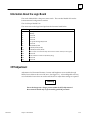
Installing the Battery
1.
Locate the small rectangular battery cover plate on the back of the OIT. Remove the
two Phillips screws from the plate, and separate the plate from the OIT. Notice how
two clips hold the battery on the back of the plate.
2.
Locate two sets of battery connections on the logic board just inside the OIT chassis.
Plug the mating connector from the battery cable onto one of the connections on the
logic board. Make sure that the notched side of the mating connector faces away
from you as you plug it in.
3.
Put the cover plate back on the OIT and replace the two screws.
Attaching the Keyboard
The OIT requires the use of an IBM PC-AT or -XT keyboard. By default, the OIT is configured to use an AT-compatible keyboard. To use an XT-compatible keyboard you will
need to change a configuration switch located inside the unit on the logic board. Refer
to the section, “Setting the Configuration Switches” found in Chapter 3.
Note
You can plug or unplug an AT-compatible keyboard while the power
remains on for the OIT. You must , however, power the OIT off before
plugging or unplugging an XT-compatible keyboard..
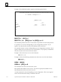
Powering-up the OIT
Plug in the OIT and turn on the AC power switch on the back of the OIT.
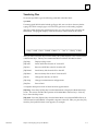
After you power-up the OIT, the following display, along with a moving video pattern,
appears on your screen:
2-2
Operator Interface Terminal User’s Manual - March 1994
GFK-0872
2
POWER–ON DIAGNOSTICS
INTERNAL BANK
00
01
02
03
04
05
06
:
:
:
:
:
:
:
32K
32K
32K
00
00
00
00
RAM
RAM
RAM
EMPTY
EMPTY
EMPTY
EMPTY
EXTERNAL BANK A
B
C
D
E
F
G
00K
00K
00K
00K
00K
00K
00K
OK
OK
OK
OK
OK
OK
OK
SYSTEM RAM : OK
VIDEO
: OK
CHARACTER RAM
: OK
EPROM CHECKSUM U61 : xxxx OK
BATTERY : OK
CLOCK : OK
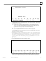
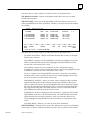
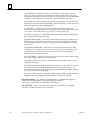
These power-up diagnostics verify the user memory of the unit as well as other internal
hardware components.
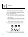
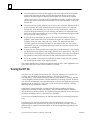
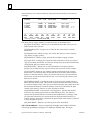
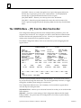
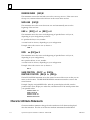
When the system completes this test, the Main Menu and Main Function Bar of the system appear, or only the Main Function Bar appears. The Main Menu and Main Function
Bar appear below:
MAIN FUNCTIONS
F1 SETUP – Setup Workstation for
power–up operation,
run demo program
F6 TOOLS – Transfer files to/from
cartridge or host,
maintain int. files
F2 SCREEN– Create or edit
graphic screen files
F7 CONFIG– Configure serial
ports, execute
diagnostic tests
F3
F8 ONLINE– Enter Online
Terminal Mode
F4
F9 LOCAL – Enter Local
Terminal Mode
F5
F10 RUN
– Run Mode selected from
Setup
_________________________________________________________________________
F1
F2
F3
F4
F5
F6
F7
F8
F9
F10
SETUP SCREEN
TOOLS CONFIG ONLINE
LOCAL
RUN
Power–up Status:
MAIN MENU
01JUN93
09:00:00
Depending on the status of your system, only the Main Function Bar may appear at the
bottom of the screen, as shown below:
________________________________________________________________________
F1
F2
F3
F4
F5
F6
F7
F8
F9
F10
SETUP SCREEN
TOOLS CONFIG ONLINE
LOCAL
RUN
Power–up Status:
GFK-0872
Chapter 2 Getting Started
MAIN MENU
1JAN08 00:00:00
2-3
2
If you do not see the diagnostic display and at least the Main Function Bar when you
power-up the system, perform the following steps until it appears:
1.
Using a flat–bladed screwdriver turn the Contrast Pot on the back of the OIT
clockwise to increase the contrast on the monitor display. (See Figure 3-1 for
location.)
Warning
Due to the dangerous voltages present within the OIT, adjustment of
these controls should only be performed by qualified personnel.
2.
Press the [Ctrl]-1 combination of keys. (Hold the [Ctrl] key down and press the 1
key that appears above the Q on the keyboard. You cannot use the numeric keypad
for this operation. Release the keys at the same time.)
You can always turn the power to the OIT off from the Main Menu or Main Function Bar
without losing any of the screens or files that you’ve created.
Using the Menu-Driven System
The menu-driven system allows you to enter the OptiSCREEN editor, specify parameters for serial communications, configure the system, and transfer screens and files to
and from a host. The menu-driven system also gives directory listings of screens and
files, and displays variables and their values.
With the menus, you press one of the [F1] through [F10] function keys to make your
selection. The system always displays valid function keys in the function bar at the bottom of the screen. After you press the key, the system displays another menu, offers a
list of screens or files from which to choose, or executes an operation:
H
When the system displays a menu, you press a function key to make another
selection.
H
When the system offers a list of files from which to choose, you use the cursor
control keys (such as [Right] and [Down] on the keypad) to highlight a file and then
press the appropriate function key to select the operation you want to perform.
H
When the system executes an operation, it completes the process and then returns
you to an appropriate menu or selection screen so that you can continue working.
To move between capabilities, you must return to the Main Function Bar. When you return to the Main Function Bar, the system outlines the menu items across the bottom of
the screen:
2-4
H
Usually you can press the [F1] MAIN function key to return to the Main Function
Bar. After you press the [F1] MAIN function key, only the Main Function Bar
appears across the bottom of the screen.
H
The [Ctrl]-1 key combination often returns you to the Main Function Bar.
Operator Interface Terminal User’s Manual - March 1994
GFK-0872
2
Within the menu-driven system, the Main Menu or the Main Function Bar appears first:
MAIN FUNCTIONS
F1 SETUP – Setup Workstation for
power–up operation,
run demo program
F6 TOOLS – Transfer files to/from
cartridge or host,
maintain int. files
F2 SCREEN– Create or edit
graphic screen files
F7 CONFIG– Configure serial
ports, execute
diagnostic tests
F3
F8 ONLINE– Enter Online
Terminal Mode
F4
F9 LOCAL – Enter Local
Terminal Mode
F5
F10 RUN
– Run Mode selected from
Setup
_________________________________________________________________________
F1
F2
F3
F4
F5
F6
F7
F8
F9
F10
SETUP SCREEN
TOOLS CONFIG ONLINE
LOCAL
RUN
Power–up Status:
MAIN MENU
01JUN93
09:00:00
The following list describes the Main Menu or Function Bar choices and their capabilities:
[F1] SETUP: Specifies what operation the OIT performs on power-up or when you
press the [F10] RUN key while using the system.
[F2] SCREEN: Enters the OptiSCREEN screen editor to create or edit a screen.
[F6] TOOLS: Enters the utility menu so that you can transfer screens, files, and data to
and from the IBM-compatible host. This item also allows you to maintain internal files.
[F7] CONFIG: Specifies the serial communications parameters, ports, and diagnostic
tests for the OIT.
[F8] ONLINE: Places your OIT in Online mode for communication with the host.
[F9] LOCAL: Places your OIT in Local mode for testing and limited operation.
[F10] RUN: Runs the mode named on the status line at the bottom of the screen. Specify the mode with the [F1] SETUP menu item from the Main Menu.
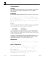
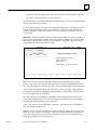
Using the Configuration Menu
Each of the Main Menu items leads you to another menu or set of selections. To start
using your OIT, you need to use the Configuration Menu.
1.
GFK-0872
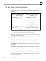
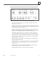
To enter the Configuration Menu, press the [F7] function key at the Main Function
Bar. The Configuration Menu appears; for example:
Chapter 2 Getting Started
2-5
2
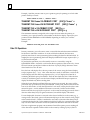
CONFIGURATION
FIRMWARE RELEASE 4.2
MODES
DATE/TIME
END LINE/COLOR
CURSOR/CRT/UNDERLINE
DISPLAY/CONTROLS
PRINT SCREEN
KEYBOARD
TESTS/BATTERY/LEVEL
PORTS/MOUSE
PORT 1
PORT 2
–UP–
UP KEY
–DOWN–
DOWN KEY
ANSI
03AUG92 DISPLAY
NO WRAP
BLINKING BLOCK
25 X 80 SCREEN
KEY OFF
35 PAD
DIAGNOSTIC
PRIMARY 1
9600 NONE
7 BIT
9600 NONE
7 BIT
–LEFT–
LEFT KEY
01JUN93
NO ECHO
SEND ANY CASE
14:51 DISPLAY
NO AUTO LF
COLOR
SCREEN SAVER OFF NO UNDERLINE
1 STATUS LINE
7 BIT CONTROLS
GENERIC ASCII
PORT 1
15 FUNCTION KEYS TERMINAL
BATTERY
CURRENT (4.2)
SECONDARY 2
NO MOUSE
1 STOP
HARD RS232
PT TO PT
1 STOP
HARD RS232
PT TO PT
–RIGHT–
RIGHT KEY
–SELECT–
BACK SPACE
–PERFORM–
ENTER
________________________________________________________________________
F1
F2
F3
F4
F5
F6
F7
F8
F9
F10
MAIN
SAVE
RECALL
RUN
FUNC
Power–up Status: MAIN MENU
The Configuration Menu specifies the serial communications parameters, ports, and
diagnostic tests for the OIT. Use the cursor control keys to move through the items.
Use the [Spacebar] to toggle through the available option settings for an item before
saving the settings, as described below.
2.
If the cursor does not already cover the first field on the screen (displaying the ANSI
setting shown above), use the cursor control keys (such as [Up] and [Left] on the
keypad) to move the cursor to that field.
3.
Press the [Spacebar] several times to display the available settings: ANSI, VT100,
and VT52. Leave the MODE item on the ANSI setting during the “Getting Started”
chapter.
4.
Use the [Down] key to move to the first field on the KEYBOARD line.
5.
Press the [Spacebar] to move through the available settings. The proper setting for
the OIT is 60 TOUCH & 35 PAD.
6.
Check the date and time display on the second line of the Configuration Menu and,
if necessary, correct them. By default, the date and time appear on the bottom line
of the screen.
7.
Check the rest of the settings on the Configuration Menu and, if any of them are
different than the ones shown above, change them to match the above settings.
8.
Press the [F5] SAVE function key to store the settings you just specified. The system
highlights the SAVE function key as it saves the menu. The system uses the stored
settings as the default whenever you power-up the system.
9.
Press the [F1] MAIN function key to return to the Main Function Bar.
Now you are ready to set the default operating mode the OIT uses when you power-up
the system.
2-6
Operator Interface Terminal User’s Manual - March 1994
GFK-0872
2
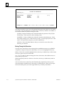
Specifying the Default Setup
In this section, you specify the Main Menu as the default operating mode for your OIT.
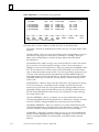
After you press the [F1] MAIN function key, the system displays the Main Function
Menu Bar:
CONFIGURATION
FIRMWARE RELEASE 4.2
MODES
DATE/TIME
END LINE/COLOR
CURSOR/CRT/UNDERLINE
DISPLAY/CONTROLS
PRINT SCREEN
KEYBOARD
TESTS/BATTERY/LEVEL
PORTS/MOUSE
PORT 1
PORT 2
–UP–
UP KEY
ANSI
03AUG92 DISPLAY
NO WRAP
BLINKING BLOCK
25 X 80 SCREEN
KEY OFF
35 PAD
DIAGNOSTIC
PRIMARY 1
9600 NONE
7 BIT
9600 NONE
7 BIT
–DOWN–
DOWN KEY
–LEFT–
LEFT KEY
01JUN93
NO ECHO
SEND ANY CASE
14:51 DISPLAY
NO AUTO LF
COLOR
SCREEN SAVER OFF NO UNDERLINE
1 STATUS LINE
7 BIT CONTROLS
GENERIC ASCII
PORT 1
15 FUNCTION KEYS TERMINAL
BATTERY
CURRENT (4.2)
SECONDARY 2
NO MOUSE
1 STOP
HARD RS232
PT TO PT
1 STOP
HARD RS232
PT TO PT
–RIGHT–
RIGHT KEY
–SELECT–
BACK SPACE
–PERFORM–
ENTER
________________________________________________________________________
F1
F2
F3
F4
F5
F6
F7
F8
F9
F10
MAIN
SAVE
RECALL
RUN
FUNC
Power–up Status: MAIN MENU
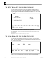
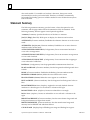
1.
To enter the Setup Menu, press the [F1] SETUP function key from the Main Function
Bar. The Setup Menu specifies the program or status that the system uses when you
power-up the system or when you press the [F10] RUN key within the system. The
Setup Menu appears below:
SETUP
Workstation Power–up Status:
MAIN MENU
1 – Display Main Menu
PRESS F10
TO RUN NOW
2 – Enter ONLINE Operation
3 – Enter LOCAL Operation
_________________________________________________________________________
F1
F2
F3
F4
F5
F6
F7
F8
F9
F10
MAIN
RUN
FUNC
Power–up Status: MAIN MENU
2.
GFK-0872
If the Setup Menu does not already specify Main Menu at the top of the menu and in
the Power-up status line at the bottom of the menu, press the 1 key (in the numeric
row above the letter Q or on the numeric keypad) to set this status.
Chapter 2 Getting Started
2-7
2
3.
To save and use the menu, press the [F1] MAIN function key or the [F10] RUN
function key. When you press the [F1] MAIN function key, only the Main Function
Bar appears at the bottom of the screen. When you press the [F10] RUN function
key, the Main Function Bar appears on the bottom of the screen and the short
descriptions for the various functions appear above the bar.
Now you are ready to enter the OptiSCREEN editor and create your first screen file.
Using the OptiSCREEN Editor
In this section of the “Getting Started” chapter, you create and display four screen files: a
text screen file, a graphics screen file, a relative graphics screen file, and a screen file that
calls the relative graphics screen file.
1.
.Press the [F1] MAIN FUNC function key and the system displays the Main Menu
and Function Bar.
MAIN FUNCTIONS
F1 SETUP – Setup Workstation for
power–up operation,
run demo program
F6 TOOLS – Transfer files to/from
cartridge or host,
maintain int. files
F2 SCREEN– Create or edit
graphic screen files
F7 CONFIG– Configure serial
ports, execute
diagnostic tests
F3
F8 ONLINE– Enter Online
Terminal Mode
F4
F9 LOCAL – Enter Local
Terminal Mode
F5
F10 RUN
– Run Mode selected from
Setup
_________________________________________________________________________
F1
F2
F3
F4
F5
F6
F7
F8
F9
F10
SETUP SCREEN
TOOLS CONFIG ONLINE
LOCAL
RUN
Power–up Status:
2.
MAIN MENU
01JUN93
09:00:00
To enter the OptiSCREEN editor for creating and editing OptiSCREEN screen files,
press the [F2] SCREEN function key.
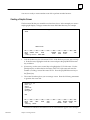
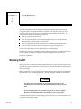
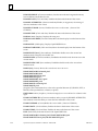
Creating a Text Screen File
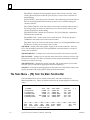
After you press the [F2] SCREEN function key at the Main Function Bar, the Screen File
Editor Directory appears. If a screen file appears (with the Editing prompt at the bottom
of the function bar), press the [F10] DIR function key to obtain the directory, as shown
below:
2-8
Operator Interface Terminal User’s Manual - March 1994
GFK-0872
2
Screen File Editor – Directory
TEST1
SELECT FILE:
TEST 1
________________________________________________________________________
F1
F2
F3
F4
F5
F6
F7
F8
F9
F10
MAIN
SYNTAX EDIT
SHOW
RENAME
COPY
DELETE
RUN
FUNC
FILE
FILE
FILE
Power–up Status: MAIN MENU
1.
Look in the directory for a file named TEST1. If the file does not exist, move to step
2. If the file exists, delete it:
A. Use the cursor control keys ([Right] and [Down], for example) to move the
cursor to cover the screen file named TEST1 in the directory. The name also
appears in the Select file prompt at the bottom of the screen.
B. Press the [F8] DELETE FILE function key to delete the screen file.
After deleting the file, the system returns you to the Screen File Editor Directory so
that you can continue working.
2.
If the directory is empty, use the keyboard to enter the name TEST1 and then press
the [F3] EDIT function key or press the [Enter] key. If another file name appears in
the directory, use the [Backspace] key to delete the name, one character at a time,
and then enter the name TEST1 before pressing the [F3] EDIT function key or the
[Enter] key.
3.
The screen file editor places you in an empty screen:
–
END
_________________________________________________________________________
F1
F2
F3
F4
F5
F6
F7
F8
F9
F10
MAIN
STEP
HELP
SHOW
SAVE
UNDO
DELETE INSER
DIR
FUNC
FILE
CHNGES
LINE
LINE
Enter the following statements to generate the screen file. Feel free to enter the
name of your company between quotes where YOUR COMPANY appears below:
GFK-0872
Chapter 2 Getting Started
2-9
2
’TEST1 – Text file
CLEAR SCREEN
MOVE TO 10, 10
QUAD SIZE
DISPLAY ”TEST 1”
BLUE
/WHITE
MOVE TO 16, 10
DISPLAY ”YOUR COMPANY”
EXIT QUAD
END
_________________________________________________________________________
F1
F2
F3
F4
F5
F6
F7
F8
F9
F10
MAIN
STEP
HELP
SHOW
SAVE
UNDO
DELETE INSERT DIR
FUNC
FILE
CHNGES
LINE
LINE
Editing: TEST1
Information about the individual statements helps you understand the purpose of
this file:
2-10
H
The first line, ’Test1 - Text file, demonstrates a comment line. Starting a line with an
apostrophe (the character two keys to the right of the L key) makes any line a
comment, or a remark, for the OptiSCREEN file. Comments help document the
purpose of statements and statements in individual files. Also, when you make the
first statement of a screen file a comment, the comment identifies the file when you
generate a file directory.
H
The CLEAR SCREEN statement clears the entire OIT screen and resets all attributes.
You see this statement at the beginning of files and whenever you want to “start
fresh” in a system.
H
The MOVE TO 10, 10 and the MOVE TO 16, 10 statements cause the text or graphics
that follow to appear in a specified location. The first MOVE statement starts the
display of text at row 10 and column 10 on the screen. The second statement starts
the display of text at row 16 and column 10. An OIT includes 25 or 30 rows,
numbered from the top of the screen to the bottom. It includes 80 or 132 columns,
numbered from the left side of the screen to the right.
H
The QUAD SIZE and EXIT QUAD statement pair are “character attribute
statements.” They affect the appearance of all text and graphics that fall between
the two statements. In general, a character fills a single cell so that it appears one
row tall and one column wide. A quad size character appears four rows tall and four
columns wide. Quad size characters appear in an uppercase (capitalized) form only.
H
The DISPLAY statement specifies the text that appears on the screen. The first
DISPLAY statement specifies the name of the file, “TEST1” and the second specifies
the name of “YOUR COMPANY.” As noted above, quad size characters appear in
uppercase only, so you must enter capitalized text.
H
Like QUAD SIZE the BLUE and /WHITE statements are character attribute
statements; they affect the appearance of all text and graphics that fall after the
statements. In this case, BLUE specifies that the text and graphics appear in blue on
the screen; /WHITE specifies that the text and graphics appear on a white
background . Other colors include RED, YELLOW, CYAN (light blue), GREEN, and
MAGENTA (purple). By placing a slash (/) immediately before these colors or
modes, you specify the background color or mode.
Operator Interface Terminal User’s Manual - March 1994
GFK-0872
2
H
The system automatically places the required END statement on the screen. When
you display the screen file again, the system deletes the blank line before the END
statement.
As you entered these statements, you may have noticed some interesting things:
GFK-0872
H
If you enter the first character or characters of a screen statement and then pause
before completing the statement, the system displays a help screen that outlines the
syntax for the statements that begin with the letter or letters you have entered. You
must set the [F3] function key to the HELP setting, rather than NOHELP, for this
feature.
H
The system automatically capitalizes the statements for you when you press the
[Enter] key to move to a new line. It does not, however, capitalize text that appears
within quotes.
H
When you press the [Enter] key, the system also correctly spells out statements that
you abbreviated or misspelled as you entered them.
H
You can use the cursor control keys to move through the screen file and make
corrections to the text.
H
You can press the [F9] INSERT LINE function key to insert a new, blank line into the
middle of the file. (The [Ctrl]-[Ins] key combination also performs this function.)
H
You can press the [F8] DELETE LINE function key to delete the line that the cursor
currently covers in the file. (The [Ctrl]-[Del] key combination also performs this
function.)
H
You can press the [Ins] key to change from replacement, or overwrite, mode to
insertion mode and add new text to the file. In insertion mode, existing text shifts to
the right to make room for the new text.
H
You can press the [Del] key to delete the character that the cursor currently covers.
Chapter 2 Getting Started
2-11
2
4.
To display the screen file at your OIT, press the [F4] SHOW function key:
TEST 1
YOUR COMPANY
This shows how the screen appears when you call it from an external device or call it
from another program.
5.
Press any key to return to the screen file for further editing:
’TEST1 – Text file
CLEAR SCREEN
MOVE TO 10, 10
QUAD SIZE
DISPLAY ”TEST 1”
BLUE
/WHITE
MOVE TO 16, 10
DISPLAY ”YOUR COMPANY”
EXIT QUAD
END
_________________________________________________________________________
F1
F2
F3
F4
F5
F6
F7
F8
F9
F10
MAIN
STEP
HELP
SHOW
SAVE
UNDO
DELETE INSERT DIR
FUNC
FILE
CHNGES
LINE
LINE
Editing: TEST1
At this point, you can add statements to the screen file or you can make changes to
the existing statements in the screen file. Press the [F4] SHOW function key to
display the screen again, and press any key to return to the screen file for further
editing.
2-12
6.
Press the [F5] SAVE function key to save the screen file you just created. The system
highlights the SAVE function key as it saves the file.
7.
Press the [F10] DIR function key to return to the Screen File Editor Directory. Notice
that the TEST1 screen file now appears in the directory.
Operator Interface Terminal User’s Manual - March 1994
GFK-0872
2
You are now ready to create another screen file or perform another function.
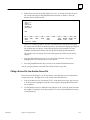
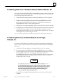
Creating a Graphic Screen
The first screen file that you created showed two lines of text. In this example you create a
simple graphic display. To begin, examine the Screen File Editor Directory; for example:
Screen File Editor – Directory
TEST1
SELECT FILE:
_________________________________________________________________________
F1
F2
F3
F4
F5
F6
F7
F8
F9
F10
MAIN
SYNTAX EDIT
SHOW
RENAME
COPY
DELETE
RUN
FUNC
FILE
FILE
FILE
Power–up Status: MAIN MENU
1.
Look in the directory for a file named TEST2. If the file does not exist, move to step
2. If the file exists, highlight it with the cursor and press the [F8] DELETE function
key to delete it.
2.
If necessary, use the cursor control keys to highlight the TEST1 file name. Use the
[Backspace] key to delete the last character of the TEST1 file name and enter the
number 2, creating a screen file named TEST2. Press the [F3] EDIT function key or
the [Enter] key.
3.
The screen file editor places you in an empty screen. Enter the following statements
to generate the screen file:
’TEST2 – Text file
MOVE TO 10, 20
BOX 8 x 8
LEFT 4
QUAD SIZE
DISPLAY ”e”
EXIT QUAD
END
_________________________________________________________________________
F1
F2
F3
F4
F5
F6
F7
F8
F9
F10
MAIN
STEP
HELP
SHOW
SAVE
UNDO
DELETE INSERT DIR
FUNC
FILE
CHNGES
LINE
LINE
Editing: TEST2
Several new statements and different uses of old statements appear in this example:
GFK-0872
Chapter 2 Getting Started
2-13
2
H
The BOX statement draws a box on the screen. In this case, the box is 8 rows tall
and 8 columns wide. The system draws boxes from the lower left-hand corner
of the box. That is, you use the MOVE TO statement to move to a specific
location on the screen, and the BOX statement draws up a specified number of
rows and to the right a specified number of columns. The cursor does not move
after you issue the BOX statement; it remains in the lower left corner of the box.
H
The LEFT statement moves the cursor left a specified number of columns. In
this case, the cursor moves to the left of the box 4 columns, the width of one
quad-sized character. OptiSCREEN also offers a RIGHT statement, an UP
statement, and a DOWN statement.
H
The lowercase e in the DISPLAY statement appears as a quad-sized graphic
character rather than a text character. This occurs since uppercase quad size
characters generate text and lowercase quad size characters generate graphics
characters.
4.
To display the screen file at your OIT, press the [F4] SHOW function key. The
lowercase e generates the graphic symbol often used for a pump on a diagram. Note
the location of the graphic and the box.
5.
Press any key to return to the screen file for further editing. At this point, you can
make changes to the existing statements in the screen file.
6.
Press the [F5] SAVE function key to save the screen file you just created. The system
highlights the SAVE function key as it saves the file.
7.
Press the [F10] DIR function key to return to the Screen File Editor Directory.
You can now perform another function at the OIT.
Changing a Screen File from Absolute to Relative
In this part of “Getting Started,” you change screen file TEST2 to make it a relative screen
file. (Descriptions of “absolute” and “relative” files appear below.) In the next part of
this chapter, you use the changed relative screen file. To begin, move to the Screen Editor File Directory:
1.
2-14
Highlight the file named TEST2 with the cursor and press the [F3] EDIT function
key or the [Enter] key. The screen editor places you in the TEST2 screen file.
Operator Interface Terminal User’s Manual - March 1994
GFK-0872
2
2.
Delete the second line in the file (MOVE TO 10, 20). To do this, move the cursor to
the second line and press the [F8] DELETE function key to delete it. After the
deletion, the file looks like this:
’TEST2 – Text file
BOX 8 x 8
LEFT 4
QUAD SIZE
DISPLAY ”e”
EXIT QUAD
END
_________________________________________________________________________
F1
F2
F3
F4
F5
F6
F7
F8
F9
F10
MAIN
STEP
HELP
SHOW
SAVE
UNDO
DELETE INSERT DIR
FUNC
FILE
CHNGES
LINE
LINE
Editing: TEST2
This is now a relative graphic screen file. The statements in the file do not display
the output from the file in an absolute position; the statements display the output in
any location that you specify. Notice that the file does not contain the CLEAR
SCREEN statement but contains both the QUAD and EXIT QUAD statements.
An example of how to display this relative file appears in the next section of this
chapter.
3.
Press the [F5] SAVE function key to save the TEST2 screen file. The system
highlights the SAVE function key as it saves the file.
4.
Press the [F10] DIR function key to return to the Screen File Editor Directory.
You can now generate the screen file that calls the relative screen file.
Calling a Screen File from Another Screen File
In this section of the chapter, you call the relative screen file that you just created from
another screen file. To begin, move to the Screen Editor File Directory:
GFK-0872
1.
Look in the directory for a file named TEST3. If the file does not exist, move to step
2. If the file exists, highlight it with the cursor and press the [F8] DELETE function
key to delete it.
2.
Use the [Backspace] key to delete the last character of the TEST2 file name and enter
the number 3, creating a screen file named TEST3. Press the [F3] EDIT function key
or the [Enter] key.
Chapter 2 Getting Started
2-15
2
3.
The screen file editor places you in an empty screen. Enter the following statements
to generate the screen file:
’TEST3 – Calling another screen file
CLEAR SCREEN
RED
MOVE TO 10, 10
DISPLAY FILE TEST2
BLUE
MOVE TO 14, 20
DISPLAY FILE TEST2
YELLOW
MOVE TO 18, 30
DISPLAY FILE TEST2
END
_________________________________________________________________________
F1
F2
F3
F4
F5
F6
F7
F8
F9
F10
MAIN
STEP
HELP
SHOW
SAVE
UNDO
DELETE INSERT DIR
FUNC
FILE
CHNGES
LINE
LINE
Editing: TEST3
The DISPLAY FILE statement in this screen file causes the system to display the
contents of screen file TEST2 in the locations, and in the colors or modes, that you
specify.
4.
To display the screen file at your OIT, press the [F4] SHOW function key. Note the
location and color of the graphics and the box as they appear on the screen.
5.
Press any key to return to the screen file for further editing. At this point, you can
make changes to the statements in the screen file.
6.
Press the [F5] SAVE function key to save the screen file. The system highlights the
SAVE function key as it saves the file.
7.
Press the [F10] DIR function key to return to the Screen File Editor Directory.
Creating a Sample Screen Format
A sample screen format is shown in the figure below. The sample format can be created
by typing in the program which is listed after the figure. The format includes a variety
of OptiSCREEN statements to help you become familiar with the overall characteristics
of screen programming.
2-16
Operator Interface Terminal User’s Manual - March 1994
GFK-0872
2
a44147
AUTO–PLATER
SELECT FUNCTION
RUN TIME Today
Week
F1 Hoist Control
F2 Rectifier Control
FAULTS
Today
Week
Figure 2-2. Sample Screen Format
The Sample Program
Comments explaining how the sample program works are included in the listing. Each
of the statements used in the sample program are explained in full in Chapter 5, OptiSCREEN Statement Reference. The recommended method for entering the program is as
follows.
GFK-0872
1.
Enter a single block of program lines at a time; the blocks are separated in the listing
by a blank comment line.
2.
After entering a block of lines, press the Show Key (F4) to display the part of the
program entered.
3.
Press any key to resume editing.
Chapter 2 Getting Started
2-17
2
ÁÁÁÁÁÁÁÁÁÁÁ
ÁÁÁ
ÁÁÁÁÁÁÁÁÁÁÁ
ÁÁÁÁÁÁÁÁÁÁÁ
ÁÁÁ
ÁÁÁÁÁÁÁÁÁÁÁ
ÁÁÁÁÁÁÁÁÁÁÁ
ÁÁÁ
ÁÁÁÁÁÁÁÁÁÁÁ
ÁÁÁÁÁÁÁÁÁÁÁ
ÁÁÁ
ÁÁÁÁÁÁÁÁÁÁÁ
ÁÁÁÁÁÁÁÁÁÁÁ
ÁÁÁ
ÁÁÁÁÁÁÁÁÁÁÁ
ÁÁÁÁÁÁÁÁÁÁÁ
ÁÁÁ
ÁÁÁÁÁÁÁÁÁÁÁ
ÁÁÁÁÁÁÁÁÁÁÁ
ÁÁÁ
ÁÁÁÁÁÁÁÁÁÁÁ
ÁÁÁÁÁÁÁÁÁÁÁ
ÁÁÁ
ÁÁÁÁÁÁÁÁÁÁÁ
ÁÁÁÁÁÁÁÁÁÁÁ
ÁÁÁ
ÁÁÁÁÁÁÁÁÁÁÁ
ÁÁÁÁÁÁÁÁÁÁÁ
ÁÁÁ
ÁÁÁÁÁÁÁÁÁÁÁ
ÁÁÁÁÁÁÁÁÁÁÁ
ÁÁÁ
ÁÁÁÁÁÁÁÁÁÁÁ
ÁÁÁÁÁÁÁÁÁÁÁ
ÁÁÁ
ÁÁÁÁÁÁÁÁÁÁÁ
ÁÁÁÁÁÁÁÁÁÁÁ
ÁÁÁ
ÁÁÁÁÁÁÁÁÁÁÁ
ÁÁÁÁÁÁÁÁÁÁÁ
ÁÁÁ
ÁÁÁÁÁÁÁÁÁÁÁ
ÁÁÁÁÁÁÁÁÁÁÁ
ÁÁÁ
ÁÁÁÁÁÁÁÁÁÁÁ
ÁÁÁÁÁÁÁÁÁÁÁ
ÁÁÁ
ÁÁÁÁÁÁÁÁÁÁÁ
ÁÁÁÁÁÁÁÁÁÁÁ
ÁÁÁ
ÁÁÁÁÁÁÁÁÁÁÁ
ÁÁÁÁÁÁÁÁÁÁÁ
ÁÁÁ
ÁÁÁÁÁÁÁÁÁÁÁ
ÁÁÁÁÁÁÁÁÁÁÁ
ÁÁÁ
ÁÁÁÁÁÁÁÁÁÁÁ
ÁÁÁÁÁÁÁÁÁÁÁ
ÁÁÁ
ÁÁÁÁÁÁÁÁÁÁÁ
ÁÁÁÁÁÁÁÁÁÁÁ
ÁÁÁ
ÁÁÁÁÁÁÁÁÁÁÁ
ÁÁÁÁÁÁÁÁÁÁÁ
ÁÁÁ
ÁÁÁÁÁÁÁÁÁÁÁ
ÁÁÁÁÁÁÁÁÁÁÁ
ÁÁÁ
ÁÁÁÁÁÁÁÁÁÁÁ
ÁÁÁÁÁÁÁÁÁÁÁ
ÁÁÁ
ÁÁÁÁÁÁÁÁÁÁÁ
ÁÁÁÁÁÁÁÁÁÁÁ
ÁÁÁ
ÁÁÁÁÁÁÁÁÁÁÁ
’Sample Screen File
’
RESET LINE ATTRIBUTES
CLEAR SCREEN
’
MOVE TO 7, 1
BOX 7 X 80
MOVE TO 5, 5
QUAD SIZE
DISPLAY ”AUTO–PLATER
EXIT QUAD
’
MOVE TO 2, 59
DISPLAY ”______________”
MOVE TO 3, 64
DISPLAY ”|”
SUPPLEMENTAL
MOVE TO 2, 61
DISPLAY ”~PP~”
MOVE TO 4, 59
DISPLAY ”lklklklklklklk”
MOVE TO 5, 59
DISPLAY ”mjmjmjmjmjmjmj”
EXIT SUPPLEMENTAL
’
MOVE TO 20, 1
BOX 12 X 38
MOVE TO 11, 4
DOUBLE WIDE
GREEN
BLINK
DISPLAY ”SELECT FUNCTION”
EXIT DOUBLE WIDE AND BLINK
RESET ATTRIBUTES
MOVE TO 14, 8
DISPLAY ”F1 Hoist Control”
MOVE TO 16, 8
DISPLAY ”F2 Rectifier Control”
2-18
This is the Screen Title
These statements draw the box
for the screen heading and display the words AUTO–PLATER in
Quad size letters. You must
use capital letters.
These statements draw the symbol for the Auto–Plater using
normal ASCII characters and
characters in the Supple–
mental character set. Be sure
to note that the Supplemeantal
character set letters are lower
case. See Appendix B for a
graphic representation of the
Supplemental characters.
These statements make up the
Select Function area. The
DOUBLE WIDE, GREEN, and BLINK
statements are used to emphasize the action to be taken.
Operator Interface Terminal User’s Manual - March 1994
GFK-0872
2
ÁÁÁÁÁÁÁÁÁÁÁÁÁ
ÁÁ
ÁÁÁÁÁÁÁÁÁÁÁÁ
ÁÁÁÁÁÁÁÁÁÁÁÁÁ
ÁÁ
ÁÁÁÁÁÁÁÁÁÁÁÁ
ÁÁÁÁÁÁÁÁÁÁÁÁÁ
ÁÁ
ÁÁÁÁÁÁÁÁÁÁÁÁ
ÁÁÁÁÁÁÁÁÁÁÁÁÁ
ÁÁ
ÁÁÁÁÁÁÁÁÁÁÁÁ
ÁÁÁÁÁÁÁÁÁÁÁÁÁ
ÁÁ
ÁÁÁÁÁÁÁÁÁÁÁÁ
ÁÁÁÁÁÁÁÁÁÁÁÁÁ
ÁÁ
ÁÁÁÁÁÁÁÁÁÁÁÁ
ÁÁ
ÁÁÁÁÁÁÁÁÁÁÁÁÁ
ÁÁÁÁÁÁÁÁÁÁÁÁ
ÁÁÁÁÁÁÁÁÁÁÁÁÁ
ÁÁ
ÁÁÁÁÁÁÁÁÁÁÁÁ
ÁÁ
ÁÁÁÁÁÁÁÁÁÁÁÁÁ
ÁÁÁÁÁÁÁÁÁÁÁÁ
ÁÁ
ÁÁÁÁÁÁÁÁÁÁÁÁÁ
ÁÁÁÁÁÁÁÁÁÁÁÁ
ÁÁÁÁÁÁÁÁÁÁÁÁÁ
ÁÁ
ÁÁÁÁÁÁÁÁÁÁÁÁ
ÁÁÁÁÁÁÁÁÁÁÁÁÁ
ÁÁ
ÁÁÁÁÁÁÁÁÁÁÁÁ
ÁÁÁÁÁÁÁÁÁÁÁÁÁ
ÁÁ
ÁÁÁÁÁÁÁÁÁÁÁÁ
ÁÁÁÁÁÁÁÁÁÁÁÁÁ
ÁÁ
ÁÁÁÁÁÁÁÁÁÁÁÁ
ÁÁÁÁÁÁÁÁÁÁÁÁÁ
ÁÁ
ÁÁÁÁÁÁÁÁÁÁÁÁ
ÁÁÁÁÁÁÁÁÁÁÁÁÁ
ÁÁ
ÁÁÁÁÁÁÁÁÁÁÁÁ
ÁÁ
ÁÁÁÁÁÁÁÁÁÁÁÁÁ
ÁÁÁÁÁÁÁÁÁÁÁÁ
ÁÁ
ÁÁÁÁÁÁÁÁÁÁÁÁÁ
ÁÁÁÁÁÁÁÁÁÁÁÁ
ÁÁÁÁÁÁÁÁÁÁÁÁÁ
ÁÁ
ÁÁÁÁÁÁÁÁÁÁÁÁ
ÁÁÁÁÁÁÁÁÁÁÁÁÁ
ÁÁ
ÁÁÁÁÁÁÁÁÁÁÁÁ
ÁÁÁÁÁÁÁÁÁÁÁÁÁ
ÁÁ
ÁÁÁÁÁÁÁÁÁÁÁÁ
ÁÁÁÁÁÁÁÁÁÁÁÁÁ
ÁÁ
ÁÁÁÁÁÁÁÁÁÁÁÁ
ÁÁ
ÁÁÁÁÁÁÁÁÁÁÁÁÁ
ÁÁÁÁÁÁÁÁÁÁÁÁ
ÁÁ
ÁÁÁÁÁÁÁÁÁÁÁÁÁ
ÁÁÁÁÁÁÁÁÁÁÁÁ
ÁÁÁÁÁÁÁÁÁÁÁÁÁ
ÁÁ
ÁÁÁÁÁÁÁÁÁÁÁÁ
ÁÁ
ÁÁÁÁÁÁÁÁÁÁÁÁÁ
ÁÁÁÁÁÁÁÁÁÁÁÁ
ÁÁÁÁÁÁÁÁÁÁÁÁÁ
ÁÁ
ÁÁÁÁÁÁÁÁÁÁÁÁ
ÁÁÁÁÁÁÁÁÁÁÁÁÁ
ÁÁ
ÁÁÁÁÁÁÁÁÁÁÁÁ
ÁÁÁÁÁÁÁÁÁÁÁÁÁ
ÁÁ
ÁÁÁÁÁÁÁÁÁÁÁÁ
ÁÁÁÁÁÁÁÁÁÁÁÁÁ
ÁÁ
ÁÁÁÁÁÁÁÁÁÁÁÁ
’
MOVE TO 20, 43
BOX 12 X 38
MOVE TO 11, 45
DOUBLE WIDE
RED
DISPLAY ”RUN TIME”
MOVE TO 15, 45
DISPLAY ”FAULTS”
RESET ATTRIBUTES
SUPPLEMENTAL
MOVE TO 11, 65
DISPLAY ”~”
MOVE TO 12, 65
DISPLAY ”~”
MOVE TO 15, 65
DISPLAY ”~”
MOVE TO 16, 65
DISPLAY ”~”
EXIT SUPPLEMENTAL
MOVE TO 11, 67
DISPLAY ”Today”
MOVE TO 12, 67
DISPLAY ”Week”
MOVE TO 15, 67
DISPLAY ”Today”
MOVE TO 16, 67
DISPLAY ”Week”
’
/BLUE
MOVE TO
DISPLAY
MOVE TO
DISPLAY
MOVE TO
DISPLAY
MOVE TO
DISPLAY
’
11, 74
”{ENQ}{ENQ}{ENQ}{ENQ}{ENQ}”
12, 74
”{ENQ}{ENQ}{ENQ}{ENQ}{ENQ}”
15, 74
”{ENQ}{ENQ}{ENQ}”
16, 74
”{ENQ}{ENQ}{ENQ}”
’
LOAD FUNCTION KEY 1 WITH ”B”
LOAD FUNCITON KEY 2 WITH ”C”
GFK-0872
Chapter 2 Getting Started
These statements form the Display RUN TIME and FAULTS areas
of the screen.
These statements are part of
the Data Fill operations explained in Chapter 5.
The Data Fill operations are
used to make it easier for the
host to place dynamic data in
different locations on the
screen. The /BLUE statement is
only included here to show
where data from the host will
be displayed. Normally, the
Data Fill statements would be a
separate file from the rest of
the screen.
These statements load function
keys F1 and F2 with the characters ”B” and ”C” respectively.
2-19
2
Now That You’ve Started
This chapter outlined a number of the basic capabilities of the OIT. The rest of this guide
and other documentation from GE Fanuc Automation expand on the information presented here:
2-20
H
Chapter 3 of this guide, “Installation,” describes the physical and electrical
requirements of the OIT.
H
Chapter 4, “Operation” describes menus and screens that the system provides, and
outlines the steps you take to use the system.
H
Chapter 5, “OptiSCREEN Statement Reference” completely describes the
OptiSCREEN statements.
H
The appendices found at the end of this guide contain information about the
physical measurements of the OIT and the symbols available in the system.
Operator Interface Terminal User’s Manual - March 1994
GFK-0872
Chapter
3 Installation
3
section level 1 1
figure bi level 1
table_big level 1
GE Fanuc Automation ships all Operator Interface Terminals (OITs) pre-tested and
configured for the most popular modes of operation. To operate the OIT, you must
mount the unit, supply AC power, and connect a serial communications cable. This
section explains hardware installation of the OIT:
H
H
How to physically mount the OIT.
H
H
How to prepare the electrical connections for communication with the OIT.
How to replace the battery and connect peripherals (such as a keyboard and
communications cable) at the rear of the OIT..
How you should set the switches and jumpers on the OIT logic board.
It also shows the locations for the adjustments of the CRT display.
In addition to requiring a compatible electrical interface between your OIT and the host
or PLC system, you must also check the software configuration of the OIT for
compatibility. More information about the software and its configuration appears in
Chapter 4, “Operation.”
Mounting the OIT
Install your OIT in a standard 19-inch industrial rack or in a special panel cutout for the
unit. When properly mounted in a sealed enclosure, the OIT maintains its NEMA 4 and
NEMA 12 ratings.
Refer to Appendix A for the required panel cutout and mounting holes for installing the
OIT. The OIT uses 10-32 mounting studs. GE Fanuc supplies nuts with lock washers to
accommodate panel mounting.
Caution
You must apply 35 inch/pounds (4 newton/meters) of torque to the
mounting studs to maintain the NEMA 4 and NEMA 12 ratings for the
OIT.
To avoid damaging the studs and the front panel, do not over-tighten
the nuts on the mounting studs. This damage is not covered by the
warranty.
You should keep the OIT box and packing materials so that you can use them if the unit
ever needs to be shipped again.
GFK-0872
3-1
3
Rear Panel Connections
The left rear of the OIT chassis contains all the connections you need during installation.
Î
ÎÎ
ÎÎ
Î
SIDE
PANEL
Î ÎÎ Î Î
ÎÎ
Î
Î
ÎÎ
ÎÎ
Î
SECONDARY
DTE
Î
Î
Î
Î
Î
ÎÎ
ÎÎ
Î
a45282
PRIMARY
DTE
SERIAL
KEYBOARD
BATTERY
COVER
AC INPUT
HORIZONTAL
POSITION
CONTRAST
HORIZONTAL
FUSE
(3 AMP SB)
BRIGHTNESS
POWER
PORT FOR
VIEWING
DIAGNOSTIC LEDs
Figure 3-1. Rear View of the OIT
A description of each of the items shown here appears in this chapter.
AC Power
The OIT uses a 115 Vac to 230 Vac (50/60Hz) wide-ranging power supply; it consumes
110 watts. A standard EIA plug is provided with the OIT. You must supply the 3-wire
AC power cord. The three terminals use the following designations.
a45302
ÎÎ
ÎÎÎÎ
ÎÎ
ÎÎÎÎ
ÎÎÎÎ
LIN
COVER
Figure 3-2. Wiring for AC Power
3-2
Operator Interface Terminal User’s Manual - March 1994
ÎÎ
Î
Î
ÎÎ
ÎÎ
Î
Î
ÎÎ
Î
ÎÎ
ÎÎ
ÎÎ
ÎÎ
ÎÎ
ÎÎ
N
GN
D
GFK-0872
3
Battery Replacement
The OIT uses a lithium battery to power the built-in clock and calendar, and to maintain
the user memory for screens and data files. The battery has a nominal shelf life of five
years, and maintains the user memory for up to a year depending upon the amount of
memory installed.
Warning
Lithium batteries cannot be recharged. Do not discard the lithium
battery in fire. Do not short the battery. The battery may burn or
release hazardous materials if damaged. Replace the battery with an
identical lithium battery.
The battery assembly consists of a battery with a short cable and a mating connector.
ÎÎ
Î
Î
ÎÎÎÎ
ÎÎ
ÎÎ
Î
a44157
Figure 3-3. Battery Assembly
To replace a battery in the OIT, perform the following steps. You do not have to remove
the OIT side panel to perform this operation:
1.
Turn off the power to the OIT.
2.
Remove the two screws which hold the battery coverplate on the back of the OIT.
3.
Two clips hold the old battery to the back of the battery coverplate. Disconnect the
old battery from the clips on the battery coverplate.
4.
A pair of two-position connections exist inside the battery coverplate opening on the
main logic board. The old battery is attached to one of the two-position connections.
While the old battery remains attached, connect the new battery to the two unused
battery connectors on the logic board. Be sure to use the notches on the battery
connector to install the battery with the correct polarity. Assuming that the old
battery retains some power, this “double battery” allows you to save any data in
user memory.
GFK-0872
5.
Remove the old battery from the battery connector on the logic board.
6.
Install the new battery in the clips on the battery coverplate.
7.
Replace the battery coverplate on the back of the OIT.
Chapter 3 Installation
3-3
3
BATTERY
COVERPLATE
CLIPS
BATTERY
a45283
ÎÎÎÎÎ
Î
ÎÎ
ÎÎÎÎÎ
ÎÎ
ÎÎÎÎÎ
Î
ÎÎÎÎÎ
ÎÎÎÎÎ
Î
ÎÎÎÎÎ
Î
ÎÎ
ÎÎ
ÎÎÎÎÎ
ÎÎÎÎÎÎ
BATTERY
CONNECTIONS
Figure 3-4. Connecting the Battery
Communication Interface
Your OIT communicates with your computer, programmable controller, or other host
device through a serial interface at RS-232C, RS-422, or RS-485 signal levels. By default
the OIT is configured for RS-232 communication. You can change this default by
changing a jumper on the logic board as described later in this chapter in the section,
“Setting the Configuration Switches”.
The 25-pin, male, D-connectors on the rear of the unit conforms to RS-232C standards.
These standards define an asynchronous serial interface, its impedances, and its physical
connectors. RS-232C standards place all equipment into one of two general categories:
H
DTE, or Data Terminal Equipment, includes most terminals, printers, and other
peripherals. DTE devices are commonly called “data terminals.”
H
DCE, or Data Communications Equipment, includes many computers and modems.
DCE devices are commonly called “data sets.”
The differences between a data terminal and a data set emerge when referring to each
device’s input and output connectors, such as the signals labeled “transmitted data” and
“received data.”
A cable wired to a DTE at one end and to a DCE at the other end allows all necessary
wires to match pin-for-pin at each end. When you connect a DTE device to another DTE
device, or you connect a DCE to a DCE, you must cross one or more pairs of signals for
proper operation:
The primary port and the secondary port are both configured as DTE ports with signals
as shown below. Make sure that your host is either a DCE device or that the connecting
cable makes the required signal pair crossovers.
With RS-232C operation, when you connect a DTE device to a DTE device, or a DCE
device to a DCE device, the signals on pins 2 and 3 must be cross connected; for example,
pin 2 at one device must be connected to pin 3 at the other. Any required handshaking
signals must also be cross connected.
The RS-232 standard defines a number of signals in addition to transmitted and received
data. Few devices require all signals to be used, and most require only a few signals.
Refer to your host equipment manual for additional information about pins and
required signals.
3-4
Operator Interface Terminal User’s Manual - March 1994
GFK-0872
3
Port Connector Definitions
Definitions for the serial port connector appears below. An illustration of the 25-pin
connector also appears for reference.
a44159
PIN 13
PIN 1
PIN 14
PIN 25
ÁÁÁ
ÁÁÁÁÁÁÁÁÁÁ
ÁÁÁ
ÁÁÁÁÁÁÁÁÁÁÁÁÁÁ
ÁÁÁ
ÁÁÁÁÁÁÁÁÁÁ
ÁÁÁ
ÁÁÁÁÁÁÁÁÁÁÁÁÁÁ
ÁÁÁ
ÁÁÁÁÁÁÁÁÁÁ
ÁÁÁ
ÁÁÁÁÁÁÁÁÁÁÁÁÁÁ
ÁÁÁ
ÁÁÁÁÁÁÁÁÁÁ
ÁÁÁ
ÁÁÁÁÁÁÁÁÁÁÁÁÁÁ
ÁÁÁ
ÁÁÁÁÁÁÁÁÁÁ
ÁÁÁ
ÁÁÁÁÁÁÁÁÁÁÁÁÁÁ
ÁÁÁ
ÁÁÁÁÁÁÁÁÁÁ
ÁÁÁ
ÁÁÁÁÁÁÁÁÁÁÁÁÁÁ
ÁÁÁ
ÁÁÁÁÁÁÁÁÁÁ
ÁÁÁ
ÁÁÁÁÁÁÁÁÁÁÁÁÁÁ
ÁÁÁ
ÁÁÁÁÁÁÁÁÁÁ
ÁÁÁ
ÁÁÁÁÁÁÁÁÁÁÁÁÁÁ
ÁÁÁ
ÁÁÁÁÁÁÁÁÁÁ
ÁÁÁ
ÁÁÁÁÁÁÁÁÁÁÁÁÁÁ
ÁÁÁ
ÁÁÁÁÁÁÁÁÁÁ
ÁÁÁ
ÁÁÁÁÁÁÁÁÁÁÁÁÁÁ
ÁÁÁ
ÁÁÁÁÁÁÁÁÁÁ
ÁÁÁ
ÁÁÁÁÁÁÁÁÁÁÁÁÁÁ
ÁÁÁ
ÁÁÁÁÁÁÁÁÁÁ
ÁÁÁ
ÁÁÁÁÁÁÁÁÁÁÁÁÁÁ
ÁÁÁ
ÁÁÁÁÁÁÁÁÁÁ
ÁÁÁ
Á
ÁÁÁÁÁÁÁÁÁÁÁÁÁ
ÁÁÁÁÁÁÁÁÁÁÁÁÁÁ
Figure 3-5. Primary and Secondary Port Using DB-25P Male Connector
Pin
Connection
Pin
1(a)
Protective (chassis) ground
14
2
TXD, Data Out, RS-232C
15
3
4 (b)
5 (c)
6
7
8
9
10
11
12
13
RXD, Data In, RS-232C
RTS (Request To Send) output
CTS (Clear To Send) input
no connection
Signal Ground
no connection
no connection
no connection
no connection
no connection
no connection
16
17
18
19 (d)
20 (e)
21 (d)
22
23
24
25
Connection
TX (+), Data Out (+), SD(B), RS-422,
also Data I/O (+) for RS-485
TX (–), Data Out (–), SD(A), RS-422,
also Data I/O (–) for RS-485
RX (+), Data In (+), RD(B), RS-422
RX (–), Data In (–), RD(A), RS-422
no connection
Terminate RX, RS-422 and RS-485
DTR (Data Terminal Ready) out
Terminate RX, RS-422 and RS-485
no connection
no connection
no connection
no connection
Notes:
(a) Use the protective ground when a chassis ground is not available with the user equipment.
(b) Asserted when input buffer space available with hardware handshaking.
(c) Must be asserted to allow output if you use hardware handshaking.
CTS (pin 5) on the serial port is used for hardware handshaking during RS-232C operation.
If the host equipment does not support the use of this signal and if software handshaking is
not selected, then you must connect CTS (pin 5) to DTR (pin 20) at the OIT‘s connector.
(d) The Terminate RX signals (pins 19 and 21) must be connected to Data In signals (pins 16 and
17) for point-to-point operation or if this OIT is at the end of a multidrop line.
For RS-422 communication:
connect pin 16 to pin 19
connect pin 17 to pin 21
For RS-485 communication:
connect pin 14 to pin 19
connect pin 15 to pin 21
For RS-485 communication, the terminator depends on the configuration of the transmission
line; refer to the RS-485 specification for proper cable termination. Also, a jumper on the
logic board must be set for RS-422 or RS-485 communication.
(e) Asserted when OIT has power.
GFK-0872
Chapter 3 Installation
3-5
3
General Information about Handshaking
Communication devices, such as Terminals and BASIC PLC modules, use handshaking
to coordinate the flow of two-way messages between two or more devices.
Handshaking is necessary for two reasons:
H
H
Handshaking prevents both devices from transmitting at the same time.
Handshaking prevents one device from sending data faster than the other can
receive it.
If you are using the OIT for display purposes only, then two-way communication never
takes place and handshaking is less of an issue. But even with “display only”
applications, many host computers can send data much faster than a Terminal can
process it. Without handshaking, you can lose critical data because the host device keeps
transmitting data, whether or not the Terminal can receive it.
ÁÁÁÁÁÁÁÁÁÁ
ÁÁÁÁÁÁÁÁÁÁÁÁÁÁÁÁÁ
ÁÁÁÁÁÁÁÁÁÁ
ÁÁÁÁÁÁÁÁÁÁÁÁÁÁÁÁÁ
ÁÁÁÁÁÁÁÁÁÁ
ÁÁÁÁÁÁÁÁÁÁÁÁÁÁÁÁÁ
ÁÁÁÁÁÁÁÁÁÁ
ÁÁÁÁÁÁÁÁÁÁÁÁÁÁÁÁÁ
ÁÁÁÁÁÁÁÁÁÁ
ÁÁÁÁÁÁÁÁÁÁÁÁÁÁÁÁÁ
ÁÁÁÁÁÁÁÁÁÁ
ÁÁÁÁÁÁÁÁÁÁÁÁÁÁÁÁÁ
ÁÁÁÁÁÁÁÁÁÁ
ÁÁÁÁÁÁÁÁÁÁÁÁÁÁÁÁÁ
ÁÁÁÁÁÁÁÁÁÁ
ÁÁÁÁÁÁÁÁÁÁÁÁÁÁÁÁÁ
ÁÁÁÁÁÁÁÁÁÁ
ÁÁÁÁÁÁÁÁÁÁÁÁÁÁÁÁÁ
ÁÁÁÁÁÁÁÁÁÁ
ÁÁÁÁÁÁÁÁÁÁÁÁÁÁÁÁÁ
ÁÁÁÁÁÁÁÁÁÁ
ÁÁÁÁÁÁÁÁÁÁÁÁÁÁÁÁÁ
ÁÁÁÁÁÁÁÁÁÁ
ÁÁÁÁÁÁÁÁÁÁÁÁÁÁÁÁÁ
ÁÁÁÁÁÁÁÁÁÁ
ÁÁÁÁÁÁÁÁÁÁÁÁÁÁÁÁÁ
ÁÁÁÁÁÁÁÁÁÁ
ÁÁÁÁÁÁÁÁÁÁÁÁÁÁÁÁÁ
ÁÁÁÁÁÁÁÁÁÁ
ÁÁÁÁÁÁÁÁÁÁÁÁÁÁÁÁÁ
ÁÁÁÁÁÁÁÁÁÁ
ÁÁÁÁÁÁÁÁÁÁÁÁÁÁÁÁÁ
ÁÁÁÁÁÁÁÁÁÁ
ÁÁÁÁÁÁÁÁÁÁÁÁÁÁÁÁÁ
ÁÁÁÁÁÁÁÁÁÁÁÁÁÁÁÁÁ
ÁÁÁÁÁÁÁÁÁÁ
ÁÁÁÁÁÁÁÁÁÁ
ÁÁÁÁÁÁÁÁÁÁÁÁÁÁÁÁÁ
ÁÁÁÁÁÁÁÁÁÁ
ÁÁÁÁÁÁÁÁÁÁÁÁÁÁÁÁÁ
ÁÁÁÁÁÁÁÁÁÁ
ÁÁÁÁÁÁÁÁÁÁÁÁÁÁÁÁÁ
ÁÁÁÁÁÁÁÁÁÁ
ÁÁÁÁÁÁÁÁÁÁÁÁÁÁÁÁÁ
ÁÁÁÁÁÁÁÁÁÁ
ÁÁÁÁÁÁÁÁÁÁÁÁÁÁÁÁÁ
ÁÁÁÁÁÁÁÁÁÁ
ÁÁÁÁÁÁÁÁÁÁÁÁÁÁÁÁÁÁÁÁÁÁÁÁÁÁÁ
ÁÁÁÁÁÁÁÁÁÁÁÁÁÁÁÁÁ
The following definitions are necessary to understand handshaking.
3-6
Hardware handshaking
A method of handshaking that uses special dedicated
signal lines to connect two devices.
Software handshaking
A method of handshaking that uses special transmitted characters to coordinate data transmissions.
Software handshaking requires fewer signal lines for
communication.
RTS - Request To Send
An output signal requesting permission to transmit
data.
CTS - Clear To Send
An input signal giving permission to transmit data.
DTR - Data Terminal Ready
An output signal, usually a constant +5 V, sent as long
as the equipment is energized.
DCD - Data Carrier Detect
An input signal. It is generally used in modem communication.
DSR - Data Set Ready
An input signal used to detect the presence of equipment at the other end of the line. It is generally used
in modem communication.
TXD - Transmit Data
An output signal used for transmitted data. Typically,
TXD is connected to RSD at the other end of an RS-232
cable.
RXD - Receive Data
An incoming signal used for received data. Typically,
RSD is connected to TXD at the other end of an RS-232
cable.
RS-232C, RS-422, and
RS-485 communications
Industry recommended standards for serial connections, serial communications, and signal characteristics.
Since these are only recommended standards, many
manufacturers do not follow all the standards, especially in regard to pin numbers.
Operator Interface Terminal User’s Manual - March 1994
GFK-0872
3
Handshaking with RS-232C Signals
The OIT offers a 256-character input FIFO (first in, first out) buffer for receiving and
holding characters until the OIT processes them. In some cases, the FIFO buffer is filled
faster than the OIT processes the characters.
“Handshaking” allows the receiving device to direct the sending device to stop
transmitting data so that the buffer does not overflow. Two modes of handshaking,
software or hardware, can be selected through system configuration.
Software handshaking occurs as follows:
H
When the FIFO buffer receives 192 characters, the OIT sends XOFF, or [Ctrl]-S, to the
host computer as a message to stop transmitting. The system loses incoming
characters only after the FIFO buffer receives 256 characters.
H
When the OIT processes enough characters so that only 64 characters remain in the
FIFO buffer, the OIT sends XON, or [Ctrl]-Q, to the host computer to indicate that it
is ready to accept more characters.
You can enable or disable software handshaking with the Configuration menu. On
initial power-up, the system defaults to hardware handshaking. After you select
software handshaking, XON or XOFF codes from the host control the flow of data from
the OIT.
The OIT handles hardware handshaking with the following signals:
H
The OIT uses the RTS (Request To Send output) signal on pin 4 of the RS-232
interface to indicate when the FIFO buffer can accept additional characters.
H
The host asserts the CTS (Clear To Send) signal on pin 5 before the OIT transmits
any data.
H
The OIT always asserts the DTR (Data Terminal Ready output) signal on pin 20
when power is on.
For either hardware or software handshaking, the host computer must be set up to
handle the handshaking information. If the host computer does not support
handshaking signals, set the OIT for hardware handshaking, and jumper the DTR
output (pin 20) to the CTS input (pin 5) on the OIT. Then, the host ignores the RTS
signal from the OIT. The OIT cannot control the flow of data from the host in this
situation, so the application program must be written to ensure that the input buffer on
the OIT does not overflow.
Handshaking with RS-422 Signals
The OIT does not support the hardware handshaking signals described above as equivalent
RS-422 signals. With RS-422 signals, the OIT supports software handshaking when you
select it. You should select hardware handshaking if the host supports no handshaking.
By default, jumpers E2 and E3 are configured for RS-232 communication. These two
jumpers are described later in this chapter.
You can use RS-422 signals on one port, while you use RS-232 signals on the other port.
You must connect RS-422 receiver termination pins at the OIT when using it in a
point-to-point configuration. In multidrop configurations, you must connect the
termination pins at the OIT farthest from the host. You can use the OIT‘s internal
termination resistors by connecting pin 16 to pin 19 and connecting pin 17 to pin 21.
GFK-0872
Chapter 3 Installation
3-7
3
Consult your host equipment supplier for additional information.
Cable and Connector Specifications
The following list provides the specifications for the construction of cables to connect the
OIT to a host device:
H
Cable connector to primary or secondary port: Female, D-subminiature type,
Cannon DB-25S with DB110963-3 hood or equivalent (standard RS-232C connector).
H
Maximum cable length: 50 feet (15 meters) for RS-232C; 4000 feet (1200 meters) for
RS-422.
H
Overall shield: Recommended. Tie the shield to the chassis ground at one end only.
See the wiring diagrams below for more information.
H
H
Minimum wire specification: 24 AWG.
Cable recommendations: High quality, twisted pair cable (two twists per inch
preferred) provides acceptable operation at data rates of up to 19.2K baud and
distances of up to 4000 feet for RS-422 ports.
Refer to your application or device manual for additional information about connections
to the host or peripherals.
When using the RS-422 port, you should match the twisted pairs so that both transmit
signals make up one twisted pair and both receive signals make up the other twisted
pair. If you ignore this crossover, cross talk affecting the performance of the
communication system can result from the mismatching.
Caution
When routing communications cables outdoors, use transient
suppression devices to reduce the possibility of damage due to
lightning or static discharge.
Also, make sure that both the OIT and the host device to which the
OIT is connected are grounded to a common point. Failure to provide
a ground can result in serious damage to the equipment if the potential
exceeds the isolation voltage rating of the equipment.
Typical Cable Wiring Configurations
This section contains cable wiring diagrams for the OIT:
3-8
H
The diagrams do not cover all possible configurations; but by using the OIT port
connector definitions and the manual for the DTE or DCE device connected to your
OIT, you should be able to configure the cable for your application.
H
All signals, with the exception of the protective ground, are optically isolated from
the OIT internal logic. The primary and secondary ports are optically isolated from
each other.
Operator Interface Terminal User’s Manual - March 1994
GFK-0872
3
The diagrams appear below.
Primary Port to Series Six ASCII/BASIC Module Port 2)
OIT
(DTE)
PRIMARY
OR
SECONDARY
PORT
25– PIN
MALE
Î
Î
Î
Î
Î
PIN
PIN
1
2
3
4
5
20
7
3
2
5
4
8
7
SHLD
TXD
RXD
RTS
CTS
DTR
GND
25– PIN
FEMALE
Î
Î
Î
Î
Î
RXD
TXD
CTS
RTS
DCD
GND
25– PIN
MALE
CHASSIS GROUND
a45284
SERIES SIX
ASCII/BASIC
MODULE
(DTE)
PORT 2
25– PIN
FEMALE
Figure 3-6. RS-232C Point-to-Point Communication with Handshaking
(OIT Serial Port to Series Six ASCII/BASIC Module Port 1 or Port 2)
OIT
(DTE)
PRIMARY
OR
SECONDARY
PORT
25– PIN
MALE
*
Î
ÎÎ
ÎÎ
Î
ÎÎ
Î
ÎÎ
Î
Î
PIN
PIN
1
2
3
5
20
7
3
2
15
16
7
SHLD
TXD
RXD
CTS
DTR
GND
25– PIN
FEMALE
*
RXD
TXD
GND
25– PIN
MALE
CHASSIS GROUND
Î
Î
Î
Î
Î
Î
ÎÎ
Î
Î
a45285
SERIES SIX
ASCII/BASIC
MODULE
(DTE)
PORT1 OR
PORT 2
25– PIN
FEMALE
IF PORT 1, MUST BE CONNECTED (SEE AS ASCII BASIC MANUAL)
Figure 3-7. RS-232C Point-to-Point Communication, No Handshaking
(OIT Serial Port to Series Six ASCII/BASIC Module Port 1 or Port 2)
OIT
(DTE)
PRIMARY
OR
SECONDARY
PORT
25– PIN
MALE
Î
Î
Î
Î
Î
Î
PIN
PIN
SHLD
1
TXD
2
3
RXD
RXD
3
2
TXD
7
GND
CTS
5
DTR
20
GND
7
25– PIN
FEMALE
CHASSIS GROUND
25– PIN
MALE
Î
Î
Î
Î
Î
Î
Î
Î
ÎÎ
Î
Î
a45286
PRINTER
OR
STR–LINK III
(DTE)
25– PIN
FEMALE
Figure 3-8. RS-232C Point-to-Point Communication (OIT Serial Port to Printer on
STR-LINK III)
OIT
PRIMARY
OR
SECONDARY
PORT
25– PIN
MALE
Î
Î
Î
Î
Î
Î
PIN
TERMRX
TERMRX
CTS
DTR
GND
SHLD
SD (A)
SD (B)
RD (A)
RD (B)
25– PIN
FEMALE
PIN
19
21
5
20
7
1
15
14
17
16
7
23
11
22
10
GND
RXD –
RXD +
TXD –
TXD +
25– PIN
MALE
Î
Î
ÎÎ
Î
Î
ÎÎ
Î
Î
ÎÎ
Î
ÎÎ
Î
ÎÎ
Î
Î
a45287
SERIES SIX
ASCII/BASIC
MODULE
25– PIN
FEMALE
CHASSIS GROUND
Figure 3-9. RS-422 Point-to-Point Communication
(OIT Serial Port to Series Six ASCII/BASIC Module Port 1 or Port 2)
GFK-0872
Chapter 3 Installation
3-9
3
OIT
(DTE)
PRIMARY
OR
SECONDARY
PORT
25– PIN
MALE
ÎÎ
Î
ÎÎ
Î
ÎÎ
Î
ÎÎ
Î
ÎÎ
Î
PIN
PIN
2
3
4
5
7
20
1
3
2
5
20
7
8
TXD
RXD
RTS
CTS
GND
DTR
25– PIN
FEMALE
CHASSIS GROUND
SHLD
RXD
TXD
CTS
DTR
GND
DCD
25– PIN
MALE
Î
Î
Î
Î
Î
a45288
SERIES
90–70
PCM
(DTE)
PORT 1
OR
PORT 2
25– PIN
FEMALE
Figure 3-10. RS-232 Point-to-Point Communication with Handshaking
(OIT Serial Port to Series 90-70 PCM Module Port 1 or Port 2)
OIT
PRIMARY
OR
SECONDARY
PORT
25– PIN
MALE
ÎÎ
Î
Î
Î
Î
Î
Î
ÎÎ
Î
Î
Î
Î
Î
ÎÎ
PIN
SD (A)
SD (B)
RD (A)
RD (B)
TERMRX
TERMRX
CTS
DTR
15
14
17
16
19
21
5
20
GND
7
24
13
25
9
21
10
11
12
22
23
TERM (RD)
RD (A)
RD (B)
SD (A)
SD (B)
RTS (A)
CTS (A)
TERM (CTS)
RTS (B)
CTS (B)
7 GND
1 SHLD
25– PIN
MALE
CHASSIS GROUND
25– PIN
FEMALE
ÎÎ
Î
Î
Î
Î
Î
Î
ÎÎ
Î
Î
Î
Î
ÎÎ
Î
ÎÎ
PIN
a45289
SERIES
90–70
PCM
PORT 1
OR
PORT 2
25– PIN
FEMALE
Figure 3-11. RS-422 Point-to-Point Communication with Handshaking
(OIT Serial Port to Series 90-70 PCM Module Port 1 or Port 2)
OIT
(DTE)
PRIMARY
OR
SECONDARY
PORT
25– PIN
MALE
Î
Î
Î
Î
Î
ÎÎ
Î
Î
ÎÎ
TXD
RXD
RTS
CTS
GND
DTR
25– PIN
FEMALE
PIN
PIN
2
3
4
5
7
20
1
3
2
5
20
7
8
CHASSIS GROUND
SHLD
RXD
TXD
CTS
DTR
GND
DCD
25– PIN
MALE
Î
Î
Î
Î
Î
a45290
SERIES
90–30
PCM
(DTE)
PORT 1
25– PIN
FEMALE
Figure 3-12. RS-232 Point-to-Point Communication with Handshaking
(OIT Serial Port to Series 90-30 PCM Module Port 1)
3-10
Operator Interface Terminal User’s Manual - March 1994
GFK-0872
3
OIT
PRIMARY
OR
SECONDARY
PORT
25– PIN
MALE
Figure 3-13.
Î
Î
ÎÎ
Î
Î
Î
Î
Î
Î
Î
ÎÎ
ÎÎ
Î
ÎÎ
Î
PIN
SD (A)
SD (B)
RD (A)
RD (B)
TERMRX
TERMRX
CTS
DTR
15
14
17
16
19
21
5
20
GND
7
25– PIN
FEMALE
PIN
24
13
25
9
21
10
11
12
22
23
TERM (RD)
RD (A)
RD (B)
SD (A)
SD (B)
RTS (A)
CTS (A)
TERM (CTS)
RTS (B)
CTS (B)
7 GND
1 SHLD
CHASSIS GROUND
25– PIN
MALE
Î
Î
ÎÎ
Î
Î
Î
Î
Î
Î
Î
ÎÎ
ÎÎ
Î
ÎÎ
Î
a45291
SERIES
90–30
PCM
PORT 2
25– PIN
FEMALE
RS-422 Point-to-Point Communication
(OIT Serial Port to Series 90-30 PCM Module Port 2)
Multidrop Operations
The OIT is designed with RS-422 interfaces so that a number of units can be linked on a
multidrop line. Multidrop protocol messages are completely interrupt driven, reducing
the delay between the end of the message and the time that the OIT places its
transmitter in a high impedance state. This permits a host to poll a number of slaves
with minimum delay between polls.
Configuring the OIT
Once you select Multidrop operation in the Configuration Menu, the system requires you
to specify an address between 00 and 99. Although addresses may fall between 00 and
99, you are limited to a maximum of 16 slaves, depending on cable lengths, connection
quality, and the communications baud rate. The 00 to 99 address identifies one of the 16
OITs for later operations. On power up, or when first selecting multidrop operation, the
OIT automatically disables itself from receiving or transmitting data.
Software handshaking when selected from the Configuration menu uses the XON (or
DC1) and XOFF (or DC3) codes to prevent transmission overruns. RS-422 multidrop
operation requires this method since it does not offer RTS and CTS signals. Also, RS-422
multidrop operation does not allow the “message data” to use the DC1 or DC3 codes.
With software handshaking, Echo operation displays operator keystrokes on the screen
immediately, even though the host has not yet received the data even though the host
has not yet received the data. For special requirements, or when the polling of OITs
takes place at high speeds, you can use No Echo operation. But the host must select No
Echo mode by sending the OIT the appropriate escape sequence.
You also can select hardware handshaking. With the multidrop protocol, hardware
handshaking operates the same as no handshaking, allowing you to use the protocol
itself as a form of handshaking:
GFK-0872
Chapter 3 Installation
3-11
3
H
When the system polls a slave, the slave transmitter is enabled from the time the
system receives the address until the host receives the end of message code. If the
host receives the end of message code while the slave is still transmitting, the system
turns the slave transmitter off and the slave saves the remaining data in the output
buffer. When the slave receives the next polling message, it continues the
transmission.
H
In a single poll, the slave can transmit the same approximate number of characters as
the number of character frame times between the slave address and the end of
message code. At a minimum, this time is the same as the number of characters
transmitted as data from the host to the slave. The host may also designate a delay
between sending the slave address and the end of message code.
After configuring the OIT with the communications specifications for your application,
enter into ONLINE mode.
Wiring for RS-422 Communications
You should make sure that extra signals from the host equipment are not connected to
RS-422 pins during RS-232C operation and, similarly, that extra signals from the host
equipment are not connected to RS-232C pins during RS-422 operation.
When an OIT has not been selected during multidrop operation, its transmit signals are
put in a high-impedance state. The host computer may require you to connect pull-up
and pull-down resistors to its receive signals to avoid spurious data when no OIT has
been selected for operation.
Support of RS-422 signals by a host device does not guarantee a multidrop
configuration. The host must be able to drive the receiving circuitry of all connected
devices. Moreover, to effectively support multiple OITs, the host software must be
capable of polling and keeping track of communications with all the OITs in an orderly
manner, and usually on a real-time basis. Consult the supplier of your host device for
additional information.
3-12
Operator Interface Terminal User’s Manual - March 1994
GFK-0872
3
SERIES SIX
ASCII/BASIC
MODULE
25– PIN
MALE
OIT
PRIMARY
OR
SECONDARY
PORT
25– PIN
MALE
OIT
PRIMARY
OR
SECONDARY
PORT
25– PIN
MALE
Î
ÎÎ
Î
ÎÎ
Î
ÎÎ
Î
ÎÎ
Î
ÎÎ
Î
ÎÎ
Î
ÎÎ
Î
ÎÎ
Î
ÎÎ
Î
ÎÎ
Î
ÎÎ
Î
ÎÎ
Î
Î
ÎÎ
Î
ÎÎ
Î
ÎÎ
Î
ÎÎ
Î
ÎÎ
Î
Î
ÎÎ
ÎÎ
Î
Î
a45292
PIN
TERM RX
RXD–
RXD+
TXD–
TXD+
GND
3
17
23
11
22
10
7
25– PIN
FEMALE
PIN
TERMRX
TERMRX
SD (A)
SD (B)
RD (A)
RD (B)
CTS
DTR
GND
19
21
15
14
17
16
5
20
7
NC
NC
25– PIN
FEMALE
PIN
TERMRX
TERMRX
SD (A)
SD (B)
RD (A)
RD (B)
CTS
DTR
GND
19
21
15
14
17
16
5
20
7
25– PIN
FEMALE
Figure 3-14. RS-422 Multidrop 2-Wire (OIT Serial Port to Series Six ASCII/BASIC Module)
GFK-0872
Chapter 3 Installation
3-13
3
SERIES
90–70
PCM
PORT 1
OR
PORT 2
25– PIN
MALE
OIT
PRIMARY
OR
SECONDARY
PORT
25– PIN
MALE
OIT
PRIMARY
OR
SECONDARY
PORT
25– PIN
MALE
Î
Î
Î
Î
Î
Î
Î
Î
Î
Î
Î
Î
Î
Î
Î
Î
Î
Î
Î
Î
Î
Î
Î
Î
a45293
PIN
RD (A)
RD (B)
TERM (RD)
SD (A)
SD (B)
RTS (A)
CTS (A)
TERM (CTS)
SHLD
RTS (B)
CTS (B)
GND
13
25
24
9
21
10
11
12
1
22
23
7
25– PIN
FEMALE
PIN
SD (A)
SD (B)
RD (A)
RD (B)
TERMRX
TERMRX
CTS
DTR
15
14
17
16
19
21
5
20
GND
7
NC
NC
CHASSIS
GROUND
25– PIN
FEMALE
PIN
SD (A)
SD (B)
RD (A)
RD (B)
TERMRX
TERMRX
CTS
DTR
15
14
17
16
19
21
5
20
GND
7
25– PIN
FEMALE
Figure 3-15. RS-422 Multidrop 4-Wire (OIT Serial Port to Series 90-70 PCM
Module Port 1 or Port 2)
3-14
Operator Interface Terminal User’s Manual - March 1994
GFK-0872
3
SERIES
90–30
PCM
PORT 2
25– PIN
MALE
OIT
PRIMARY
OR
SECONDARY
PORT
25– PIN
MALE
OIT
PRIMARY
OR
SECONDARY
PORT
25– PIN
MALE
Î
Î
Î
Î
Î
Î
Î
Î
Î
Î
Î
Î
Î
Î
Î
Î
Î
Î
Î
Î
Î
Î
Î
Î
a45294
PIN
RD (A)
RD (B)
TERM (RD)
SD (A)
SD (B)
RTS (A)
CTS (A)
TERM (CTS)
SHLD
RTS (B)
CTS (B)
GND
13
25
24
9
21
10
11
12
1
22
23
7
25– PIN
FEMALE
PIN
SD (A)
SD (B)
RD (A)
RD (B)
TERMRX
TERMRX
CTS
DTR
15
14
17
16
19
21
5
20
GND
7
NC
NC
CHASSIS
GROUND
25– PIN
FEMALE
PIN
SD (A)
SD (B)
RD (A)
RD (B)
TERMRX
TERMRX
CTS
DTR
15
14
17
16
19
21
5
20
GND
7
25– PIN
FEMALE
Figure 3-16. RS-422 Multidrop 4-Wire (OIT Serial Port or Secondary Port to
Series 90-30 PCM Module Port 2)
GFK-0872
Chapter 3 Installation
3-15
3
RS-422 Communication with Pull-Up Resistors
Some terminal applications that connect an OIT to a host RS-422 device encounter junk
characters displayed on the screen or misinterpreted escape codes. This problem occurs
when the OIT receives spurious data during the interval when the host device releases
the RS-422 transmit line. During this release interval, the receive input line is in a
tri-state, or floating mode, that is highly susceptible to noise or cross-coupling signal
pickup within the cable. Resolve this problem by adding two 10K resistors to the receive
lines as shown below.
OIT
PRIMARY
OR
SECONDARY
PORT
25– PIN
MALE
Î
Î
Î
Î
Î
Î
Î
PIN
TERMRX
TERMRX
CTS
DTR
RD
RD
TD
TD
19
21
5
20
17
16
15
14
GND
7
25– PIN
FEMALE
a45355
10K
10K
Figure 3-17. RS-422 Communication with Pull-Up Resistors
The resistors condition the receive input lines to an off state when the host is in a
tri-state, or floating mode. The system uses the DTR signal for a positive voltage source
for the pull-up resistor on the RD (+) line. Even with the 10 K resistors installed, it may
be necessary to connect the terminating resistors at the “receive input” for long cables.
How Multidrop Operation Works
A typical sequence for a host device to poll a series of RS-422 slaves appears below:
1.
To enable your OIT for both transmission and reception, the host sends [Ctrl]-P
(Data Link Escape, or ASCII code 16) followed by the two digit address for the
desired OIT. The address appears in standard ASCII format and uses two digits; for
example, the system addresses OIT 5 as 05. For example, the host transmits the
following ASCII codes:
16 48 49
ASCII code 16 is [Ctrl]-P. ASCII code 48 is 0. ASCII code 49 is 1. This sequence
initiates communications with slave 1.
3-16
2.
The system transmits the “message string” to the host. The system displays
keyboard entries on the screen and stores them for subsequent transmission. The
system stores a maximum of 256 characters before it loses data. Once you select an
OIT, any keyboard entries being stored are automatically transmitted as the message
string, and normal operation (as if point-to-point connection were in effect) takes
place between the host and the OIT.
3.
The host transmits a series of escape sequences to the slave.
Operator Interface Terminal User’s Manual - March 1994
GFK-0872
3
4.
The host can subsequently disable a OIT by sending [Ctrl]-W (End of Transmission
Block, or ASCII code 23). For example, two-way communication continues until the
hosts transmits the following ASCII code:
23
ASCII code 23 is [Ctrl]-W. This sequence ends communications with slave 1.
5.
Continuing, the host transmits the following ASCII codes:
16 48 50
ASCII code 16 is [Ctrl]-P. ASCII code 48 is 0. ASCII code 50 is 2. This sequence initiates
communications with slave 2.
And so on, until all of the multidrop devices have been polled.
The system automatically enables an OIT with the address 00 to receive data addressed
to any OIT, but the OIT is not enabled to transmit unless the host specifically transmits
the 00 address. If the host transmits the address 00, all OITs are enabled to receive data,
but only OIT 00 (if it exists) is enabled to transmit data.
Multiple OITs may use the same address, but only one OIT with the given address may
be electrically connected to transmit data.
Similarly, more than one address may be enabled at the same time. Simply transmit the
enabling code for an address (without an intervening [Ctrl]-W code), followed by the
message string for the address; then transmit the enabling code for an address, followed
by a message string, and so on. Again, however, only one OIT may be electrically
connected for transmitting data.
The OIT uses the control codes for enabling and disabling ports in the same sequence as
it does for all other commands and characters. Therefore, the system processes all
commands and characters it receives before it executes a command to relinquish the
multidrop link. Also, the host command to establish a new connection cannot be sent
until the OIT relinquishes the previous connection. Therefore, you may be required to
specify a delay between turning off one OIT and turning on another to prevent more
than one OIT from operating simultaneously. The OIT holds up to 255 characters in its
buffer and generally processes over 1000 characters per second; therefore, a 1/8th second
delay (0.125 second) should be adequate unless you send a complex escape sequence,
such as a screen display.
Setting the Configuration Switches
Eight configuration switches are accessed through a side panel on the back of the OIT.
(See Figure 3-1 for location of the Side Panel.) Avoid unplugging the electrical harnesses
from the power supply, the fan, or the video board. Note the location and orientation of
any harnesses you do disconnect for reinstallation on the logic board.
Warning
High voltages are present in the OIT while power is connected, even
after the OIT is turned off. Unplug the OIT before removing the side
panel.
GFK-0872
Chapter 3 Installation
3-17
3
Caution
The electronic logic board is subject to damage by static electricity.
Make sure that you are properly grounded before touching the logic
board.
The default settings for the switches are shown below.
a45306
ON
OFF
1
2
3
4
5
6
7
8
Figure 3-18. Default Switch Settings for the OIT
3-18
Operator Interface Terminal User’s Manual - March 1994
GFK-0872
3
ÁÁÁÁ
ÁÁÁÁÁÁÁÁÁÁÁÁÁÁÁÁÁÁÁÁÁÁÁÁÁÁÁ
ÁÁÁÁ
ÁÁÁÁ
ÁÁÁÁÁÁÁÁÁÁÁÁÁÁÁÁÁÁÁÁÁÁÁÁ
ÁÁÁÁÁÁÁÁÁÁÁÁÁÁÁÁÁÁÁÁÁÁÁÁÁÁÁ
ÁÁÁÁ
ÁÁÁÁ
ÁÁÁÁÁÁÁÁÁÁÁÁÁÁÁÁÁÁÁÁÁÁÁÁ
ÁÁÁÁ
ÁÁÁÁ
ÁÁÁÁÁÁÁÁÁÁÁÁÁÁÁÁÁÁÁÁÁÁÁÁ
ÁÁÁÁ
ÁÁÁÁ
ÁÁÁÁÁÁÁÁÁÁÁÁÁÁÁÁÁÁÁÁÁÁÁÁ
ÁÁÁÁ
ÁÁÁÁÁÁÁÁÁÁÁÁÁÁÁÁÁÁÁÁÁÁÁÁÁÁÁ
ÁÁÁÁ
ÁÁÁÁÁÁÁÁÁÁÁÁÁÁÁÁÁÁÁÁÁÁÁÁ
ÁÁÁÁ
ÁÁÁÁÁÁÁÁÁÁÁÁÁÁÁÁÁÁÁÁÁÁÁÁÁÁÁ
ÁÁÁÁ
ÁÁÁÁÁÁÁÁÁÁÁÁÁÁÁÁÁÁÁÁÁÁÁÁ
ÁÁÁÁ
ÁÁÁÁ
ÁÁÁÁ
ÁÁÁÁÁÁÁÁÁÁÁÁÁÁÁÁÁÁÁÁÁÁÁÁ
ÁÁÁÁ
ÁÁÁÁÁÁÁÁÁÁÁÁÁÁÁÁÁÁÁÁÁÁÁÁÁÁÁ
ÁÁÁÁ
ÁÁÁÁÁÁÁÁÁÁÁÁÁÁÁÁÁÁÁÁÁÁÁÁÁÁÁ
ÁÁÁÁ
ÁÁÁÁÁÁÁÁÁÁÁÁÁÁÁÁÁÁÁÁÁÁÁÁ
ÁÁÁÁ
ÁÁÁÁ
ÁÁÁÁÁÁÁÁÁÁÁÁÁÁÁÁÁÁÁÁÁÁÁÁ
ÁÁÁÁ
ÁÁÁÁÁÁÁÁÁÁÁÁÁÁÁÁÁÁÁÁÁÁÁÁÁÁÁÁ
ÁÁÁÁ
ÁÁÁÁÁÁÁÁÁÁÁÁÁÁÁÁÁÁÁÁÁÁÁÁÁÁÁ
ÁÁÁÁ
ÁÁÁÁÁÁÁÁÁÁÁÁÁÁÁÁÁÁÁÁÁÁÁÁÁÁÁ
ÁÁÁÁ
ÁÁÁÁÁÁÁÁÁÁÁÁÁÁÁÁÁÁÁÁÁÁÁÁ
ÁÁÁÁ
ÁÁÁÁ
ÁÁÁÁÁÁÁÁÁÁÁÁÁÁÁÁÁÁÁÁÁÁÁÁ
ÁÁÁÁ
ÁÁÁÁ
ÁÁÁÁÁÁÁÁÁÁÁÁÁÁÁÁÁÁÁÁÁÁÁÁ
ÁÁÁÁ
ÁÁÁÁÁÁÁÁÁÁÁÁÁÁÁÁÁÁÁÁÁÁÁÁÁÁÁ
ÁÁÁÁ
ÁÁÁÁÁÁÁÁÁÁÁÁÁÁÁÁÁÁÁÁÁÁÁÁ
ÁÁÁÁ
ÁÁÁÁÁÁÁÁÁÁÁÁÁÁÁÁÁÁÁÁÁÁÁÁÁÁÁ
ÁÁÁÁ
ÁÁÁÁ
ÁÁÁÁÁÁÁÁÁÁÁÁÁÁÁÁÁÁÁÁÁÁÁÁÁÁÁ
ÁÁÁÁÁÁÁÁÁÁÁÁÁÁÁÁÁÁÁÁÁÁÁÁ
ÁÁÁÁ
ÁÁÁÁ
ÁÁÁÁÁÁÁÁÁÁÁÁÁÁÁÁÁÁÁÁÁÁÁÁ
ÁÁÁÁÁÁÁÁÁÁÁÁÁÁÁÁÁÁÁÁÁÁÁÁÁÁÁÁ
ÁÁÁÁ
ÁÁÁÁ
ÁÁÁÁ
ÁÁÁÁÁÁÁÁÁÁÁÁÁÁÁÁÁÁÁÁÁÁÁÁ
ÁÁÁÁ
ÁÁÁÁÁÁÁÁÁÁÁÁÁÁÁÁÁÁÁÁÁÁÁÁÁÁÁ
ÁÁÁÁ
ÁÁÁÁÁÁÁÁÁÁÁÁÁÁÁÁÁÁÁÁÁÁÁÁÁÁÁ
ÁÁÁÁ
ÁÁÁÁÁÁÁÁÁÁÁÁÁÁÁÁÁÁÁÁÁÁÁÁ
ÁÁÁÁ
ÁÁÁÁÁÁÁÁÁÁÁÁÁÁÁÁÁÁÁÁÁÁÁÁÁÁÁ
ÁÁÁÁ
ÁÁÁÁÁÁÁÁÁÁÁÁÁÁÁÁÁÁÁÁÁÁÁÁ
ÁÁÁÁ
ÁÁÁÁ
ÁÁÁÁ
ÁÁÁÁÁÁÁÁÁÁÁÁÁÁÁÁÁÁÁÁÁÁÁÁ
ÁÁÁÁ
ÁÁÁÁÁÁÁÁÁÁÁÁÁÁÁÁÁÁÁÁÁÁÁÁÁÁÁ
ÁÁÁÁ
ÁÁÁÁÁÁÁÁÁÁÁÁÁÁÁÁÁÁÁÁÁÁÁÁ
ÁÁÁÁ
ÁÁÁÁÁÁÁÁÁÁÁÁÁÁÁÁÁÁÁÁÁÁÁÁÁÁÁ
ÁÁÁÁ
ÁÁÁÁÁÁÁÁÁÁÁÁÁÁÁÁÁÁÁÁÁÁÁÁÁÁÁ
ÁÁÁÁ
ÁÁÁÁ
ÁÁÁÁÁÁÁÁÁÁÁÁÁÁÁÁÁÁÁÁÁÁÁÁ
ÁÁÁÁÁÁÁÁÁÁÁÁÁÁÁÁÁÁÁÁÁÁÁÁÁÁÁ
ÁÁÁÁ
ÁÁÁÁ
ÁÁÁÁÁÁÁÁÁÁÁÁÁÁÁÁÁÁÁÁÁÁÁÁ
ÁÁÁÁÁÁÁÁÁÁÁÁÁÁÁÁÁÁÁÁÁÁÁÁÁÁÁÁÁÁÁÁ
Switch 1
Switch 2
Switch 3
Switch 4
Switch 5
Switch 6
GFK-0872
This switch sets the status for the manufacturing power-ondiagnostics.
Setting
Description
On
Off
Manufacturing diagnostics cycle enabled
Manufacturing diagnostics cycle disabled (Default)
Vertical sync polarity.
Setting
Description
Off
Required
Horizontal sync polarity.
Setting
Description
Off
Required
This switch specifies the type of keyboard used with the OIT.
Setting
Description
On
Off
IBM XT-compatibleinput
IBM AT-compatible input (Default)
This switch specifies the action that the OIT takes after discovering an error during the diagnostic
test cycling.
Setting
Description
On
Off
Continues operation on test failure
Halts operation on test failure and displays status code on diagnostic LEDs (Default)
This switch specifies whether or not a keystroke repeats when you hold down a key. The automatic
keystroke repeat can be important for sealed-membrane and touch screen keyboardoperation.
Setting
Description
On
Off
Enables automatic keystroke repeating
Disables automatic keystroke repeating (Default)
Switch 7
Not used.
Switch 8
Display type.
Setting
Description
On
Required
Chapter 3 Installation
3-19
3
Interpreting the Diagnostic Status Codes
The eight diagnostic LEDs, located on the logic board (left of the switches SW2), provide
information about the operation of your OIT. These LEDs may be viewed through a
labeled slot in the side panel, without having to remove the side panel. The status codes
are described below.
o indicates that the LED is illuminated.
– indicates that the LED is dark.
ÁÁÁ
ÁÁÁÁÁÁÁ
ÁÁÁÁÁÁÁÁÁÁÁÁÁÁÁÁÁÁÁ
ÁÁÁ
ÁÁÁÁÁÁÁ
ÁÁÁÁÁÁÁÁÁÁÁÁÁÁÁÁÁÁÁ
ÁÁÁ
ÁÁÁÁÁÁÁ
ÁÁÁÁÁÁÁÁÁÁÁÁÁÁÁÁÁÁÁ
ÁÁÁ
ÁÁÁÁÁÁÁ
ÁÁÁÁÁÁÁÁÁÁÁÁÁÁÁÁÁÁÁ
ÁÁÁ
ÁÁÁÁÁÁÁ
ÁÁÁÁÁÁÁÁÁÁÁÁÁÁÁÁÁÁÁ
ÁÁÁ
ÁÁÁÁÁÁÁ
ÁÁÁÁÁÁÁÁÁÁÁÁÁÁÁÁÁÁÁ
ÁÁÁ
ÁÁÁÁÁÁÁ
ÁÁÁÁÁÁÁÁÁÁÁÁÁÁÁÁÁÁÁ
ÁÁÁ
ÁÁÁÁÁÁÁ
ÁÁÁÁÁÁÁÁÁÁÁÁÁÁÁÁÁÁÁ
ÁÁÁ
ÁÁÁÁÁÁÁ
ÁÁÁÁÁÁÁÁÁÁÁÁÁÁÁÁÁÁÁ
ÁÁÁ
ÁÁÁÁÁÁÁ
ÁÁÁÁÁÁÁÁÁÁÁÁÁÁÁÁÁÁÁ
ÁÁÁ
Á
ÁÁÁÁÁÁÁ
ÁÁÁÁÁÁ
Á
ÁÁÁÁÁÁÁÁÁÁÁÁÁÁÁÁÁÁÁ
ÁÁÁÁÁÁÁÁÁÁÁÁÁÁÁÁÁÁ
ÁÁÁ
ÁÁÁÁÁÁÁ
ÁÁÁÁÁÁÁÁÁÁÁÁÁÁÁÁÁÁÁ
ÁÁÁ
ÁÁÁÁÁÁÁ
ÁÁÁÁÁÁÁÁÁÁÁÁÁÁÁÁÁÁÁ
ÁÁÁ
ÁÁÁÁÁÁÁ
ÁÁÁÁÁÁÁÁÁÁÁÁÁÁÁÁÁÁÁ
ÁÁÁ
ÁÁÁÁÁÁÁ
ÁÁÁÁÁÁÁÁÁÁÁÁÁÁÁÁÁÁÁ
ÁÁÁ
ÁÁÁÁÁÁÁ
ÁÁÁÁÁÁÁÁÁÁÁÁÁÁÁÁÁÁÁ
ÁÁÁ
ÁÁÁÁÁÁÁ
ÁÁÁÁÁÁÁÁÁÁÁÁÁÁÁÁÁÁÁ
ÁÁÁ
ÁÁÁÁÁÁÁ
ÁÁÁÁÁÁÁÁÁÁÁÁÁÁÁÁÁÁÁ
ÁÁÁ
ÁÁÁÁÁÁÁ
ÁÁÁÁÁÁÁÁÁÁÁÁÁÁÁÁÁÁÁ
ÁÁÁ
ÁÁÁÁÁÁÁ
ÁÁÁÁÁÁÁÁÁÁÁÁÁÁÁÁÁÁÁ
ÁÁÁ
ÁÁÁÁÁÁÁ
ÁÁÁÁÁÁÁÁÁÁÁÁÁÁÁÁÁÁÁ
ÁÁÁ
ÁÁÁÁÁÁÁ
ÁÁÁÁÁÁÁÁÁÁÁÁÁÁÁÁÁÁÁ
ÁÁÁ
ÁÁÁÁÁÁÁ
ÁÁÁÁÁÁÁÁÁÁÁÁÁÁÁÁÁÁÁ
ÁÁÁ
ÁÁÁÁÁÁÁ
ÁÁÁÁÁÁÁÁÁÁÁÁÁÁÁÁÁÁÁ
ÁÁÁ
ÁÁÁÁÁÁÁ
ÁÁÁÁÁÁÁÁÁÁÁÁÁÁÁÁÁÁÁ
ÁÁÁ
ÁÁÁÁÁÁÁ
ÁÁÁÁÁÁÁÁÁÁÁÁÁÁÁÁÁÁÁ
ÁÁÁ
ÁÁÁÁÁÁÁ
ÁÁÁÁÁÁÁÁÁÁÁÁÁÁÁÁÁÁÁ
ÁÁÁ
ÁÁÁÁÁÁÁ
ÁÁÁÁÁÁÁÁÁÁÁÁÁÁÁÁÁÁÁ
ÁÁÁ
ÁÁÁÁÁÁÁ
ÁÁÁÁÁÁÁÁÁÁÁÁÁÁÁÁÁÁÁ
ÁÁÁ
ÁÁÁÁÁÁÁ
ÁÁÁÁÁÁÁÁÁÁÁÁÁÁÁÁÁÁÁ
ÁÁÁ
ÁÁÁÁÁÁÁ
ÁÁÁÁÁÁÁÁÁÁÁÁÁÁÁÁÁÁÁ
ÁÁÁ
ÁÁÁÁÁÁÁ
ÁÁÁÁÁÁÁÁÁÁÁÁÁÁÁÁÁÁÁ
ÁÁÁ
ÁÁÁÁÁÁÁ
ÁÁÁÁÁÁÁÁÁÁÁÁÁÁÁÁÁÁÁ
ÁÁÁ
ÁÁÁÁÁÁÁ
ÁÁÁÁÁÁÁÁÁÁÁÁÁÁÁÁÁÁÁ
3-20
Seq.
No
8 7 6 5 4 3 2 1
Description
0
1
2
3
4
o
o
o
o
o
o
o
o
o
o
o
o
o
o
o
o
o
o
o
o
o
o
o
o
o
o
o
o
o
–
o
o
–
–
o
o
–
o
–
o
Power on, CPU not running; check U61, and CPU clock
Trap, invalid code was executed
CPU failed to initialize; check U35 and U61
System RAM test failed; check SIMM U2 at 2000 to 3FFF
Stack test failed; check U35, SIMM U2 at 2000 to 3FFF
5
6
7
8
9
o
o
o
o
o
o
o
o
o
o
o
o
o
o
o
o
o
o
o
o
o
o
o
–
–
–
–
–
o
o
o
–
–
o
o
–
o
–
o
–
Access
Access
Access
Access
Access
to
to
to
to
to
code
code
code
code
code
area
area
area
area
area
A1
A2
A3
A4
A5
10
11
12
13
14
o
o
o
o
o
o
o
o
o
o
o
o
o
o
o
o
o
o
o
o
–
–
–
–
–
o
o
–
–
–
–
–
o
o
–
o
–
o
–
o
Access
Access
Access
Access
Access
to
to
to
to
to
code
code
code
code
code
area
area
area
area
area
A6 failed; check U61 at 18000
A7 failed; check U61 at 1C000
A8 failed; check U53 at 0000
A9 failed; check U53 at 4000
A10 failed; check U53 at 8000
15
16
17
18
19
o
o
o
o
o
o
o
o
o
o
o
o
o
o
o
o
–
–
–
–
–
o
o
o
o
–
o
o
o
o
–
o
o
–
–
–
o
–
o
–
Access
Access
Access
Access
Access
to
to
to
to
to
code
code
code
code
code
area
area
area
area
area
A11
A12
A13
A14
A15
20
21
22
23
24
o
o
o
o
o
o
o
o
o
o
o
o
o
o
o
–
–
–
–
–
o
o
o
o
–
–
–
–
–
o
o
o
–
–
o
o
–
o
–
o
Code check sum error; check U61
Code check sum error; check U61
Code check sum error; check U53
Code check sum error; check U53
Access to power–on diagnostic test failed
25
o o o – – o o –
26
o o o – – o – o
27
o o o – – o – –
28
o o o – – – o o
29
o o o – – – o –
30
o o o – – – – o
31
o o o – – – – –
RAM extension
0000–1FFF
RAM extension
0000–1FFF
RAM extension
0000–1FFF
RAM extension
4000–7FFF
RAM extension
4000–7FFF
failed;
failed;
failed;
failed;
failed;
failed;
failed;
failed;
failed;
failed;
check
check
check
check
check
check
check
check
check
check
U61
U61
U61
U61
U61
U53
U53
U53
U53
U53
at
at
at
at
at
at
at
at
at
at
4000
8000
C000
10000
14000
C000
10000
14000
18000
1C000
1, all bits on; check SIMM U2 at
1, address key; check SIMM U2 at
1, all bits off; check SIMM U2 at
1, all bits on; check SIMM U2 at
1, address key; check SIMM U2 at
RAM extension 2, all bits off; check SIMM U2 at
4000–7FFF
ASCII 0 register tests; check CPU U35
Operator Interface Terminal User’s Manual - March 1994
GFK-0872
3
ÁÁÁ
ÁÁÁÁÁÁÁ
ÁÁÁÁÁÁÁÁÁÁÁÁÁÁÁÁÁÁÁ
ÁÁÁ
ÁÁÁÁÁÁÁ
ÁÁÁÁÁÁÁÁÁÁÁÁÁÁÁÁÁÁÁ
ÁÁÁ
Á
ÁÁÁÁÁÁÁ
ÁÁÁÁÁÁ
Á
ÁÁÁÁÁÁÁÁÁÁÁÁÁÁÁÁÁÁÁ
ÁÁÁÁÁÁÁÁÁÁÁÁÁÁÁÁÁÁ
ÁÁÁ
ÁÁÁÁÁÁÁ
ÁÁÁÁÁÁÁÁÁÁÁÁÁÁÁÁÁÁÁ
ÁÁÁ
ÁÁÁÁÁÁÁ
ÁÁÁÁÁÁÁÁÁÁÁÁÁÁÁÁÁÁÁ
ÁÁÁ
ÁÁÁÁÁÁÁ
ÁÁÁÁÁÁÁÁÁÁÁÁÁÁÁÁÁÁÁ
ÁÁÁ
ÁÁÁÁÁÁÁ
ÁÁÁÁÁÁÁÁÁÁÁÁÁÁÁÁÁÁÁ
ÁÁÁ
ÁÁÁÁÁÁÁ
ÁÁÁÁÁÁÁÁÁÁÁÁÁÁÁÁÁÁÁ
ÁÁÁ
ÁÁÁÁÁÁÁ
ÁÁÁÁÁÁÁÁÁÁÁÁÁÁÁÁÁÁÁ
ÁÁÁ
ÁÁÁÁÁÁÁ
ÁÁÁÁÁÁÁÁÁÁÁÁÁÁÁÁÁÁÁ
ÁÁÁ
ÁÁÁÁÁÁÁ
ÁÁÁÁÁÁÁÁÁÁÁÁÁÁÁÁÁÁÁ
ÁÁÁ
ÁÁÁÁÁÁÁ
ÁÁÁÁÁÁÁÁÁÁÁÁÁÁÁÁÁÁÁ
ÁÁÁ
ÁÁÁÁÁÁÁ
ÁÁÁÁÁÁÁÁÁÁÁÁÁÁÁÁÁÁÁ
ÁÁÁ
ÁÁÁÁÁÁÁ
ÁÁÁÁÁÁÁÁÁÁÁÁÁÁÁÁÁÁÁ
ÁÁÁ
ÁÁÁÁÁÁÁ
ÁÁÁÁÁÁÁÁÁÁÁÁÁÁÁÁÁÁÁ
ÁÁÁ
ÁÁÁÁÁÁÁ
ÁÁÁÁÁÁÁÁÁÁÁÁÁÁÁÁÁÁÁ
ÁÁÁ
ÁÁÁÁÁÁÁ
ÁÁÁÁÁÁÁÁÁÁÁÁÁÁÁÁÁÁÁ
ÁÁÁ
ÁÁÁÁÁÁÁ
ÁÁÁÁÁÁÁÁÁÁÁÁÁÁÁÁÁÁÁ
ÁÁÁ
ÁÁÁÁÁÁÁ
ÁÁÁÁÁÁÁÁÁÁÁÁÁÁÁÁÁÁÁ
ÁÁÁ
ÁÁÁÁÁÁÁ
ÁÁÁÁÁÁÁÁÁÁÁÁÁÁÁÁÁÁÁ
ÁÁÁ
ÁÁÁÁÁÁÁ
ÁÁÁÁÁÁÁÁÁÁÁÁÁÁÁÁÁÁÁ
GFK-0872
40
o o – o – o o o
41
o o – o – o o –
50
o o – – o o – o
51
54
o o – – o o – –
o o – – o – – o
CSIO register tests; check CPU U35
55
o o – – o – – –
Timer register tests; check CPU U35
64
o – o o o o o o
65
o – o o o o o –
100
o – – o o – o o
101
o – – o o – o –
112
o – – – o o o o
113
114
o – – – o o o –
o – – – o o – o
Video memory, all bits on; check U17 and U27
Video memory, address key; check U17 and U27
115
116
117
118
119
o
o
o
o
o
Video memory,
Character set
Character set
Character set
unused
128
o – – – – – – –
–
–
–
–
–
–
–
–
–
–
–
–
–
–
–
o
o
o
o
o
Chapter 3 Installation
o
–
–
–
–
–
o
o
–
–
–
o
–
o
–
ASCII 1 register tests; check CPU U35
DMA register tests; check CPU U35
Reserved for VDC register tests; check VDC U2
all bits off; check U17 and U27
memory, all bits on, check U32
memory, address key; check U32
memory, all bits off; check U32
OIT running, all systems normal
3-21
3
Logic Board Jumpers
Jumpers on the OIT specify the appearance of the screen and RS-232, RS-422, and
RS-485 communications for the two serial ports.
The jumpers are located on the logic board. Refer to the instructions on accessing the
logic board in the section , “Setting the Configuration Switches,” earlier in this chapter.
a45295
SERIAL
DTE
KEYBOARD
Figure 3-19. Logic Board-Memory Chip Location
3-22
Operator Interface Terminal User’s Manual - March 1994
GFK-0872
3
All jumpers are configured for proper operation when shipped. You are responsible for
verifying the jumper configuration when you change the configuration of the OIT, or
when you install a new logic board.
The following table shows the jumper configuration and descriptions for the jumper
locations on the logic board.
ÁÁÁÁÁ
ÁÁÁÁÁÁÁÁÁÁÁÁÁÁÁÁÁÁÁÁÁÁÁÁÁÁÁÁ
ÁÁÁÁÁ
ÁÁÁÁÁÁÁÁÁÁÁÁÁÁÁÁÁÁÁÁÁÁÁÁÁÁÁÁ
ÁÁÁÁÁ
ÁÁÁÁÁÁÁÁÁÁÁÁÁÁÁÁÁÁÁÁÁÁÁÁÁÁÁÁ
ÁÁÁÁÁ
ÁÁÁÁÁÁÁÁÁÁÁÁÁÁÁÁÁÁÁÁÁÁÁÁ
ÁÁÁÁÁ
ÁÁÁÁÁ
ÁÁÁÁÁÁÁÁÁÁÁÁÁÁÁÁÁÁÁÁÁÁÁÁ
ÁÁÁÁÁ
ÁÁÁÁÁ
ÁÁÁÁÁÁÁÁÁÁÁÁÁÁÁÁÁÁÁÁÁÁÁÁ
ÁÁÁÁÁÁÁÁÁÁÁÁÁÁÁÁÁÁÁÁÁÁÁÁÁÁÁÁÁÁÁÁÁÁ
Jumper E1
Jumper E1 specifies underlining and enables or disables the foreground color. To display a
concave or convex box, however, you must disable underlining.
Jumper
Description
2-3 and 4-5
1-2 and 3-4
Underlining enabled, foreground color disabled.
Underlining disabled, foreground color enabled (Default).
a45306
1
2
3
4
5
1
Positions 2–3 and 4–5
Underlining Enabled
Foreground Color Disabled
2
3
4
5
Positions 1-2 and 3-4
Underlining Disabled
Foreground Color Enabled
ÁÁÁÁÁ
ÁÁÁÁÁÁÁÁÁÁÁÁÁÁÁÁÁÁÁÁÁÁÁÁÁÁÁÁ
ÁÁÁÁÁ
ÁÁÁÁÁÁÁÁÁÁÁÁÁÁÁÁÁÁÁÁÁÁÁÁÁÁÁÁ
ÁÁÁÁÁ
ÁÁÁÁÁÁÁÁÁÁÁÁÁÁÁÁÁÁÁÁÁÁÁÁ
ÁÁÁÁÁ
ÁÁÁÁÁ
ÁÁÁÁÁÁÁÁÁÁÁÁÁÁÁÁÁÁÁÁÁÁÁÁ
ÁÁÁÁÁÁÁÁÁÁÁÁÁÁÁÁÁÁÁÁÁÁÁÁÁÁÁÁÁÁÁÁÁÁ
ÁÁÁÁÁ
ÁÁÁÁÁ
ÁÁÁÁÁÁÁÁÁÁÁÁÁÁÁÁÁÁÁÁÁÁÁÁ
ÁÁÁÁÁÁÁÁÁÁÁÁÁÁÁÁÁÁÁÁÁÁÁÁÁÁÁÁÁÁÁÁÁÁ
Jumper E2
Jumper E2 specifies the signal levels for communication channel #1.
Jumper
Description
2-4
2-3
1-2
RS-232 hardware enabled
RS-422 hardware enabled (Default)
RS-485 hardware enabled
a45307
1
4
2
1
4
2
3
Positions 2–4
RS–232 Operation
3
Positions 2–3
RS–422 Operatio
1
4
2
3
Positions 1–2
RS-485 Operation
Note
With jumper E2 in the 2-3 position to enable RS-422 operation, RS-232
can still be used on the primary port (port 1) by selecting it in the
configuration menu. This jumper only needs to be modified to enable
RS-485 operation. Placing the jumper in the 2-4 position to enable
RS-232 operation disables both RS-422 and RS-485 operation.
GFK-0872
Chapter 3 Installation
3-23
3
ÁÁÁÁÁ
ÁÁÁÁÁÁÁÁÁÁÁÁÁÁÁÁÁÁÁÁÁÁÁÁÁÁÁÁ
ÁÁÁÁÁ
ÁÁÁÁÁ
ÁÁÁÁÁÁÁÁÁÁÁÁÁÁÁÁÁÁÁÁÁÁÁÁ
ÁÁÁÁÁÁÁÁÁÁÁÁÁÁÁÁÁÁÁÁÁÁÁÁÁÁÁÁ
ÁÁÁÁÁ
ÁÁÁÁÁ
ÁÁÁÁÁÁÁÁÁÁÁÁÁÁÁÁÁÁÁÁÁÁÁÁ
ÁÁÁÁÁ
ÁÁÁÁÁ
ÁÁÁÁÁÁÁÁÁÁÁÁÁÁÁÁÁÁÁÁÁÁÁÁ
ÁÁÁÁÁ
ÁÁÁÁÁ
ÁÁÁÁÁÁÁÁÁÁÁÁÁÁÁÁÁÁÁÁÁÁÁÁ
ÁÁÁÁÁÁÁÁÁÁÁÁÁÁÁÁÁÁÁÁÁÁÁÁÁÁÁÁÁÁÁÁÁÁ
Jumper E3
Jumper E3 specifies the signal levels for communication channel #2.
Jumper
Description
2-4
2-3
1-2
RS-232 hardware enabled
RS-422 hardware enabled (Default)
RS-485 hardware enabled
The E3 jumpers use the same positions as those shown under the “Jumper 2” heading.
Note
With jumper E3 in the 2-3 position to enable RS-422 operation, RS-232
can still be used on the secondary port (port 2) by selecting it in the
configuration menu. This jumper only needs to be modified to enable
RS-485 operation. Placing the jumper in the 2-4 position to enable
RS-232 operation disables both RS-422 and RS-485 operation.
ÁÁÁÁÁ
ÁÁÁÁÁÁÁÁÁÁÁÁÁÁÁÁÁÁÁÁÁÁÁÁÁÁÁÁ
ÁÁÁÁÁ
ÁÁÁÁÁÁÁÁÁÁÁÁÁÁÁÁÁÁÁÁÁÁÁÁÁÁÁÁ
ÁÁÁÁÁ
ÁÁÁÁÁÁÁÁÁÁÁÁÁÁÁÁÁÁÁÁÁÁÁÁ
ÁÁÁÁÁ
ÁÁÁÁÁ
ÁÁÁÁÁÁÁÁÁÁÁÁÁÁÁÁÁÁÁÁÁÁÁÁ
ÁÁÁÁÁ
ÁÁÁÁÁ
ÁÁÁÁÁÁÁÁÁÁÁÁÁÁÁÁÁÁÁÁÁÁÁÁ
ÁÁÁÁÁÁÁÁÁÁÁÁÁÁÁÁÁÁÁÁÁÁÁÁÁÁÁÁÁÁÁÁÁÁ
Jumper E4
Jumper E4 specifies the software blink function.
Jumper
Description
1-2
2-3
Blink disabled, super characters enabled
Blink enabled, super characters disabled (Default)
a45308
1
2
3
Position 1–2
Blink Disabled
1
2
3
Position 2-3
Blink Enabled
The E4 jumper determines the BLINK or SUPER operation of the OIT with the
OptiSCREEN system. Use the drawing of the logic board to locate the E4 jumper which
appears near the E1 jumper and the U45 firmware slot.
If you enable the BLINK character set with the E4 jumper, you can specify “blinking” as
the current character attribute with the OptiSCREEN BLINK statement. You cannot,
however, specify “super” characters with the SUPER statement.
The BLINK and SUPER statements perform identical operations. The OIT uses the
jumper setting to determine which operation is appropriate. With the BLINK function,
the OIT loads the same character set into both the non-super and super character areas.
3-24
Operator Interface Terminal User’s Manual - March 1994
GFK-0872
3
Information About the Logic Board
The switch labeled SW1 is the power reset switch. The switches labeled SW2 are the
bottom-mounted configuration switches.
The clock chip is labeled U29.
ÁÁÁÁ
ÁÁÁÁÁÁÁÁÁÁÁÁÁÁÁÁÁÁÁÁÁ
ÁÁÁÁ
ÁÁÁÁÁÁÁÁÁÁÁÁÁÁÁÁÁÁÁÁÁ
ÁÁÁÁ
ÁÁÁÁÁÁÁÁÁÁÁÁÁÁÁÁÁÁÁÁÁ
ÁÁÁÁ
ÁÁÁÁÁÁÁÁÁÁÁÁÁÁÁÁÁÁÁÁÁ
ÁÁÁÁ
ÁÁÁÁÁÁÁÁÁÁÁÁÁÁÁÁÁÁÁÁÁ
ÁÁÁÁ
ÁÁÁÁÁÁÁÁÁÁÁÁÁÁÁÁÁÁÁÁÁ
ÁÁÁÁ
ÁÁÁÁÁÁÁÁÁÁÁÁÁÁÁÁÁÁÁÁÁ
ÁÁÁÁ
ÁÁÁÁÁÁÁÁÁÁÁÁÁÁÁÁÁÁÁÁÁ
ÁÁÁÁ
ÁÁÁÁÁÁÁÁÁÁÁÁÁÁÁÁÁÁÁÁÁ
ÁÁÁÁ
ÁÁÁÁÁÁÁÁÁÁÁÁÁÁÁÁÁÁÁÁÁ
ÁÁÁÁ
ÁÁÁÁÁÁÁÁÁÁÁÁÁÁÁÁÁÁÁÁÁ
ÁÁÁÁ
ÁÁÁÁÁÁÁÁÁÁÁÁÁÁÁÁÁÁÁÁÁ
ÁÁÁÁ
ÁÁÁÁÁÁÁÁÁÁÁÁÁÁÁÁÁÁÁÁÁ
ÁÁÁÁ
ÁÁÁÁÁÁÁÁÁÁÁÁÁÁÁÁÁÁÁÁÁ
ÁÁÁÁ
ÁÁÁÁÁÁÁÁÁÁÁÁÁÁÁÁÁÁÁÁÁ
The connectors on the logic board perform the functions listed below:
Label
Connection
P1
P2
P3
P4
P5
P6
P7
P8
P9
P10
P11
P12
P13
P14
P15
Battery
Battery
not used
not used
not used
35-position integral keyboard
not used
Parallel keyboard
COM1 (Primary DTE)
COM2 (Secondary DTE)
Power (Pin 1 is red on the logic board. Pin 1 is blue on the power supply.)
not used
Color interface connector (Note key plug)
not used
not used
CRT Adjustment
Adjustments for Horizontal Position, Contrast and Brightness are accessible through
labeled access holes in the rear of the unit. (See Figure 3-1.) A knowledgeable user may
use a flat-bladed screwdriver to reach inside the OIT to adjust these settings as required.
Warning
Due to the dangerous voltages present within the OIT, adjustment of
these controls should only be performed by qualified personnel.
GFK-0872
Chapter 3 Installation
3-25
Chapter
4 Operation
4
section level 1 1
figure bi level 1
table_big level 1
This chapter outlines the system available for entering the OptiSCREEN editors,
configuring the system, and transferring screens and files to and from a host with the
menu–driven system. The menu–driven system also gives directory listings of screens
and files, and displays variables and their values. With a full–travel keyboard attached
to the OIT, these capabilities increase the ease–of–use and speed of development for
applications by providing the following features:
H
H
The system displays valid function keys in the function bar at the bottom of the
screen. You press one of the [F1] through [F10] function keys to make your
selection. After you press the key, the system displays another menu, offers a list of
screens or files to choose from, or executes an operation:
h
When the system displays another menu, you press another function key to
make another selection.
h
When the system offers a list of screens or files, you use the cursor control keys
(the “arrow keys” labeled ↑, ↓, ←, and → on the keypad) to highlight a screen or
file and then press the appropriate function key to select the operation you want
to perform.
h
When the system executes an operation, it completes the process and then
returns you to the appropriate menu or screen so that you can continue
working.
To move between the choices displayed on the main function bar, you must always
return to the main function bar before selecting another choice. The following
diagram shows the relationship of the various menu choices
a45309
(F1)
Setup
(F2)
Screen
(F6)
Tools
Main Function Bar
(F7)
Config
H
GFK-0872
(F8)
Online
(F9)
Local
(F10)
Run
You can return to the main function bar from almost any point in the system by
pressing the [Ctrl]– [1] combination of keys. Also, most menus allow you to “back
out” of the menu by pressing one or more function keys. In many cases, you can
simply press the [F1] function key to return to the main function bar.
4-1
4
H
On color models function keys that appear in red in the function bar at the bottom
of the screen represent the most powerful and important choices on the menu.
Functions keys that appear in blue represent helpful and convenience–oriented
choices on the menu. For example, the [F1] MAIN function key appears in red in the
function bar at the bottom of the screen when you can press it to return to the main
function bar.
H
The menu–driven system makes it easy for you to move between different kinds of
screens and files. The red [F1] MAIN menu item usually returns you to the main
function bar. From that menu you can select a variety of operations. When you
return to the menu item that you were working with before you entered the main
menu, the screen or the file that you were working with automatically appears with
the cursor exactly where you left it.
H
In general, the system makes the entry of all screen and file names as simple as
possible. If the name of the screen or file does not appear in a selection screen (for
example, when you create a file with a new name), you must enter the name
yourself. Uppercase and lowercase letters do not matter in this case. For editing
convenience, you can use the [Backspace] key to erase the last letter or letters in the
name of an existing file.
H
In most cases the same item falls in the same place on different menus. For example,
the MAIN menu item appears with the [F1] function key in most menus. The SAVE
menu item (if it exists) appears with the [F5] function key. This helps you remember
the operation of the various function keys and makes the firmware easier to use.
H
If you do not make a valid menu item selection or make a valid entry for a prompt,
the system does not make any changes by default.
This chapter describes the GE Fanuc Automation family of OITs. Some capabilities, such
as the color CRT, may or may not be available on your OIT.
Turning the OIT On
The power on/off switch is located at the rear of the OIT. Whenever you turn the unit
on, allow the CRT about 30 seconds to warm up. The OIT first performs
self–diagnostics. Tests include verification that all system memory is working, that the
various peripheral circuits function, and that the battery is working properly. If all tests
pass, the OIT automatically enters the Main Menu or executes the application previously
specified to run at power–up. If any test or tests fail, the system displays a message
indicating the type of failure or failures.
If the battery voltage falls below a certain level, the “Battery Problem” message is
displayed as a warning to replace the battery. The first time this happens, a limited
amount of battery life may remain. To keep from losing the memory, do not remove the
old battery assembly until you connect the new assembly.
If you have not installed the battery, the OIT fails the battery test, indicating a diagnotic
error.
If all the tests pass, the OIT automatically enters the Main Menu or executes the
application previously specified to run at power–up. If the above test fails, you may
press any key to continue to the Main Menu or execute the application specified to run
at power–up.
4-2
Operator Interface Terminal User’s Manual - March 1994
GFK-0872
4
The Main Menu – The Main Function Bar
Within the menu system, the main function menu and main function bar appear first;
for example:
MAIN FUNCTIONS
F1 SETUP – Setup Workstation for
power–up operation,
run demo program
F6 TOOLS – Transfer files to/from
cartridge or host,
maintain int. files
F2 SCREEN– Create or edit
graphic screen files
F7 CONFIG– Configure serial
ports, execute
diagnostic tests
F3
F8 ONLINE– Enter Online
Terminal Mode
F4
F9 LOCAL – Enter Local
Terminal Mode
F5
F10 RUN
– Run Mode selected from
Setup
_______________________________________________________________________
F1
F2
F3
F4
F5
F6
F7
F8
F9
F10
SETUP SCREEN
TOOLS CONFIG ONLINE
LOCAL RUN
Power–up Status:
MAIN MENU
01JUN93
09:00:00
The menu choices, with a summary of what each does, appear below:
[F1] SETUP – Specifies the status of the OIT when you power–up the OIT or press the
[F10] RUN key while using the system.
[F2] SCREEN – Enters the OptiSCREEN screen editor so that you can create or edit a
screen.
[F6] TOOLS – Enters the utility menu so that you can transfer screens, files, and data to
and from an IBM–compatible host. This item also performs housekeeping operations
on internal files.
[F7] CONFIG – Specifies the serial communications parameters, ports, and diagnostic
tests for the OIT.
[F8] ONLINE – Specifies that the system enters the Online mode for communication.
[F9] LOCAL – Specifies that the system enters the Local mode for testing and operation.
[F10] RUN – Executes the application named on the power–up status line at the
bottom of the screen. Specify the application with the [F1] SETUP menu item from the
main menu.
Each of these menu items leads you to another menu or set of selections. The menus
and selections appear below.
GFK-0872
Chapter 4 Operation
4-3
4
The SETUP Menu – [F1] from the Main Function Bar
This menu specifies the application or status to be executed or displayed when you
power–up the system or when you press the [F10] RUN key from within the system.
This menu displays the current setting of the SETUP item at the top of the menu and in
the power–up status line at the bottom of the screen; for example:
SETUP
Workstation Power–up Status:
MAIN MENU
1 – Display Main Menu
PRESS F10
TO RUN NOW
2 – Enter ONLINE Operation
3 – Enter LOCAL Operation
_________________________________________________________________________
F1
F2
F3
F4
F5
F6
F7
F8
F9
F10
MAIN
RUN
FUNC
Power–up Status: MAIN MENU
The menu choices, with a summary of what each does, appear below:
[F1] MAIN FUNC – Returns to the main function bar so that you can make another
menu selection.
[F10] RUN – Executes the selected Power–Up status.
The Screen Menu – [F2] from the Main Function Bar
This menu enters the OptiSCREEN screen file editor so that you can create or edit a
screen. The system displays a directory of OptiSCREEN files and prompts you to “Select
file” from the list; for example:
SCREEN FILE – DIRECTORY
FILE1
FILE5
FILE9
FILE13
FILE17
SELECT FILE:
FILE2
OPAL
FILE10
FILE14
QUARTZ
FILE7
GARNET
FILE15
FILE4
FLINT
FILE12
FILE16
QUARTZ
_________________________________________________________________________
F1
F2
F3
F4
F5
F6
F7
F8
F9
F10
MAIN
SYNTAX
EDIT
SHOW
RENAME
COPY
DELETE
RUN
FUNC
FILE
FILE
FILE
Power–up Status: MAIN MENU
Use the cursor control keys to move through the OptiSCREEN names and highlight the
screen you want to work with before you press one of the function keys described
4-4
Operator Interface Terminal User’s Manual - March 1994
GFK-0872
4
below. The system displays the first line comment, or “description”, of the file at the top
of the screen above the directory of file names. To create a new file, use the [Backspace]
key to delete one or more characters of the current screen name and enter the name of
the new file in response to the “Select file” prompt. The file that you select or enter is
called the “current file.”
The menu choices, with a summary of what each does, are described below:
[F1] MAIN FUNC – Returns you to the main function bar so that you can make another
menu selection. When you return to this SCREEN menu, the system recalls the screen
on which you were working when you pressed the [F1] MAIN menu selection.
[F2] SYNTAX – Displays, in alphabetic order, the statement and parameter syntax for all
of the OptiSCREEN statements. Use the [↑] and [↓] cursor control keys to move through
the list of statements. Press one of the following function keys to exit the syntax list:
[F1] MAIN FUNC – Returns to the main function bar so that you can make another
menu selection.
[F3] EDIT FILE – Returns to the current OptiSCREEN screen file for further editing
of the file.
[F10] DIR – Returns to the OptiSCREEN screen file directory so that you can create
or select another screen.
[F3] EDIT – Places you in the OptiSCREEN EDIT menu so that you can edit the current
screen file; for example
’Text for “Blower ON”
MOVE TO 10, 10
DOUBLE WIDE
DISPLAY “Blower ON”
MOVE TO 11, 32
BOX 3 x 4
_________________________________________________________________________
F1
F2
F3
F4
F5
F6
F7
F8
F9
F10
MAIN
STEP
HELP
SHOW
SAVE
UNDO
DELETE INSERT
DIR
FUNC
FILE
CHNGES
LINE
LINE
EDITING: MYFILE2
The menu choices, with a summary of what each does, appear below. Each of the
choices operates on the current screen file (named at the bottom of the screen) which
you selected from the directory or entered in response to the “Select file” prompt:
[F1] MAIN FUNC – Saves the current screen file and returns the main function bar
so that you can make another menu selection. When you return to the SCREEN
menu, the system recalls the screen on which you were working when you pressed
the [F1] MAIN FUNC menu selection.
[F2] STEP – Graphically displays statements in the current screen file from the top
of the file to the line where your cursor currently rests. By pressing the [↓] cursor
key, the system graphically executes the next line in the file. By repeatedly pressing
the [↓] cursor key, you can work through the file line–by–line,
statement–by–statement. After viewing the results of the screen file, press any
function key to return to the screen file for further editing.
[F3] HELP– Toggles between HELP and NOHELP settings. The system starts with
the HELP setting so that if you enter the first characters of a statement and then
pause before completing it, the system displays a help screen that outlines the
syntax for the statements that begin with the letters you’ve entered. If you press the
[F3] to select the NOHELP setting, the system disables the help screen feature.
GFK-0872
Chapter 4 Operation
4-5
4
[F4] SHOW – Displays the entire graphic output of the current screen file. After
viewing the results of the screen file, press any key to return to the screen file for
further editing.
[F5] SAVE FILE – Saves the current screen file. After informing you that the file has
been saved, the [F5] SAVE FILE function key allows you to continue editing the
current screen file.
[F7] UNDO CHNGES – Exits the current version of the screen file without saving
any changes that you made to it and returns you to the last saved version of the
current screen file for further editing.
[F8] DELETE LINE – Deletes the current line. The [Ctrl]– [Del] key combination
also deletes the current line.
[F9] INSERT LINE – Inserts a line at the current location. The [Ctrl]– [Ins] key
combination also inserts a line at the current location.
[F10] DIR – Saves the current screen file and returns you to the OptiSCREEN screen
file directory so that you can create or edit a screen.
[F4] SHOW – Displays the entire graphic output of the current screen file. Press any
key to exit the display and return to the OptiSCREEN screen file directory to select or
create a new screen file.
[F6] RENAME FILE – Prompts you to enter the new name for the current screen file.
[F7] COPY FILE – Prompts you to enter the name of the file to which you want to copy
the current screen file. If it does not already exist, the system automatically creates the
file that you name for the copy.
[F8] DELETE FILE – Deletes the current screen file. The system queries you to make
sure that you have selected the appropriate file before deleting it.
[F10] RUN – Executes the mode displayed on the status line at the bottom of the screen.
Specify the mode with the [F1] SETUP menu from the main menu.
The Tools Menu – [F6] from the Main Function Bar
The Tools Menu allows you to transfer screens, files, and data to and from an
IBM–compatible host. After you make this selection, the system displays the following
menu:
TOOLS
FILENAME
1
2
3
4
5
FASTDISPLAY
SLOWDISPLAY
RETURNDISPLAY
RETURNDISPLAY
DEFAULTDISPLAY
TYPE
SCREEN
SCREEN
SCREEN
BAK SCREEN
SCREEN
SIZE
322
310
215
215
280
TITLE VALUE
LOCATION
SCREEN
SCREEN
SCREEN
SCREEN
SCREEN
INT
INT
INT
INT
INT
ONE
TWO
THREE
THREE
FOUR
S
P
1:D5DB
1:C22F
2:BD33
2:C260
1:C300
_________________________________________________________________________
F1
F2
F3
F4
F5
F6
F7
F8
F9
F10
MAIN
FILE
FILE
USER
CART
SW SEC DEFRAG
OPTI
RUN
FUNC
TYPES SERVIC ROMING
RIDGE URITY
MENT
TALK
Power–up Status: DISPLAY MAIN MENU
4-6
Operator Interface Terminal User’s Manual - March 1994
GFK-0872
4
The menu choices, with a summary of what each does, are described below:
[F1] MAIN FUNCTION – Returns to the Main Function Bar so that you can make
another menu selection.
[F2] FILE TYPES – Places you in the Types Menu of the Tools Menu so that you can
select OptiSCREEN screen files, system files, variables, or all types of files and variables;
for example:
TOOLS – Select File Type
1
2
3
4
FILENAME
TYPE
CHIPCONVEYER1
CHIPCONVEYER2
CHIPCONVEYER3
CHIPCONVEYER4
SCREEN
SCREEN
SCREEN
SCREEN
SIZE
322
310
215
280
TITLE VALUE
LOCATION
SCREEN
SCREEN
SCREEN
SCREEN
INT
INT
INT
INT
ONE
TWO
THREE
FOUR
S
P
1:D5DB
1:C22F
2:BD33
1:C300
_________________________________________________________________________
F1
F2
F3
F4
F5
F6
F7
F8
F9
F10
MAIN
SCREEN
SYSTEM
VARS
ALL
ORG/BK DFAULT EXIT
FUNC
MENU
Power–up Status: DISPLAY MAIN MENU
The menu choices, with a summary of what each does, are described below:
[F1] MAIN FUNCTION – Returns to the Main Function Bar so that you can make
another menu selection.
[F2] SCREEN – Displays a list of OptiSCREEN screen files available on the system.
After you make this selection, the system highlights the [F2] SCREEN key in the
function bar at the bottom of the screen.
[F4] SYSTEM – Displays a list of system files, such as configuration settings,
available on the system. After you make this selection, the system highlights the [F4]
SYSTEM key in the function bar at the bottom of the screen.
[F7] ALL – Displays a list of OptiSCREEN screen files, system files, and variables
and their values. After you make this selection, the system highlights the [F7] ALL
key in the function bar at the bottom of the screen.
[F8] ORIGINAL/ BACKUP – Moves, or rotates, among original, backup, and both
original and backup files for the currently selected types available on the system.
After you make this selection, the system highlights ORG when displaying original
files only, BK when displaying backup files only, or ORG/BK when displaying both
the original and backup files. This menu selection works in conjunction with the
[F2] SCREEN function through the [F7] ALL function.
[F9] DEFAULT – Defines all application files for selection. Application files include
OptiSCREEN screen files, user–defined data files, and COM communication files;
application files do not include system files. After you make this selection, the
system highlights the [F9] DEFAULT key in the function bar at the bottom of the
screen.
[F10] EXIT MENU – Returns you to the top level of the Tools Menu.
[F3] FILE SERVICE – Renames a file, copies a file, deletes one or more files, and defines
where a file is created or where the file may be moved. The two paths for files include
GFK-0872
Chapter 4 Operation
4-7
4
internal memory (for on–board memory chips) and external memory (for a memory
cartridge).
Tools – File Service
FILENAME
TYPE
SIZE
TITLE VALUE
LOCATION
S P
________________________________________________________________________
1
2
3
4
QUARTZ
GYPSUM
SHALE
BAUXITE
SCREEN
SCREEN
SCREEN
SCREEN
12
130
215
28
SCREEN
SCREEN
SCREEN
SCREEN
ONE
TWO
THREE
FOUR
INT
INT
INT
INT
1:2026
1:1036
2:50D2
1:0300
P
P
E
I
________________________________________________________________________
F1
F2
F3
F4
F5
F6
F7
F8
F9
F10
MAIN
RENAME
MARK
MARK
COPY
DELETE
ANY
INT
EXT
EXIT
FUNC
FILE
A FILE
ALL
FILE
FILES
PATH
PATH
PATH MENU
Power–up Status: DISPLAY MAIN MENU
The menu choices, with a summary of what each does, are described below:
[F1] MAIN FUNCTION – Returns you to the Main Function Bar so that you can
make another menu selection.
[F2] RENAME A FILE – Prompts you to enter the new name for the currently
selected file.
[F3] MARK A FILE – Marks, or flags, one or more files that you want to rename,
copy, delete, or apply a path to.
[F4] MARK ALL – Marks, or flags, all of the files to delete or apply a path to.
[F5] COPY FILE – Prompts you to enter the name of the file to which you want to
copy the currently selected file. If it does not already exist, the system automatically
creates the file that you name for the copy.
[F6] DELETE FILE – Deletes one or more marked files. This menu selection
prompts you to make sure that you have chosen the correct file or files to delete.
[F7] ANY PATH – Removes any memory location specification for all currently
selected files. This function allows all selected files to be stored in either internal
memory or external memory. After you press this function key, the system leaves
the file in its current location and removes any I or E from the path column of the
directory for the file.
[F8] INTERNAL PATH – Specifies the memory location for all currently selected
files as internal memory only. This function ensures that all selected files are stored
in on–board memory chips. After you press this function key, the system moves the
file from external memory to internal memory, if necessary, and marks the path
column of the directory with an I to show the path for the file.
[F9] EXTERNAL PATH – This function is not supported. Specifies the memory
location for all currently selected files as external memory only. This function
ensures that all selected files are stored in the removable memory cartridge. After
you press this function key, the system moves the file from internal memory to
external memory, if necessary, and marks the path column of the directory with an E
to show the path for the file.
[F10] EXIT MENU – Returns you to the top level of the Tools Menu.
[F4] USER ROMMING – Stores an application in ROM in either 128K or 256K byte
one–time programmable cartridges, or in 128K byte EPROM chips. Storing an
4-8
Operator Interface Terminal User’s Manual - March 1994
GFK-0872
4
application in ROM produces a cartridge or chips which you install in an OIT to ensure
that an application is permanent and secure against unexpected or deliberate changes.
Tools – User Application ROMing
FILENAME
TYPE
SIZE
TITLE VALUE
LOCATION
S P
________________________________________________________________________
1
2
3
4
QUARTZ
GYPSUM
SHALE
BAUXITE
SCREEN
SCREEN
SCREEN
SCREEN
12
130
215
28
SCREEN
SCREEN
SCREEN
SCREEN
ONE
TWO
THREE
FOUR
INT
INT
INT
INT
1:2026
1:1036
2:50D2
1:0300
P
P
E
I
________________________________________________________________________
F1
F2
F3
F4
F5
F6
F7
F8
F9
F10
MAIN
BAUD
KIND
BANKS
SEND
SEND
DEFRAG
PORT EXIT
FUNC
9600
OPTALK 0 TO 3 ROM 47 ROM 45 MENT
1
MENU
Power–up Status: DISPLAY MAIN MENU
The menu choices, with a summary of what each does, are described below:
[F1] MAIN FUNCTION – Returns you to the Main Function Bar so that you can
make another menu selection.
[F2] BAUD – Moves, or rotates, through the list of baud rates that appears below the
function key to specify the rate for your communication. Available rates include 300,
600, 1200, 2400, 4800, 9600, and 19200 baud.
[F3] KIND – Toggles between the OptiTALK and the Hex settings. To capture the
files on a PC with OptiTALK, set KIND to the OptiTALK setting. To send raw data in
the files to a PC or a programming device, set KIND to the Hex setting.
[F4] BANKS – Toggles between the 0 to 3 and the A to D settings. If the files you
want to ROM reside in internal memory, set BANKS to 0 to 3. If the files reside in
the external memory cartridge, set BANKS to A to D (this function is not supported).
[F5] SEND ROM 47 – Sends the files stored in ROM chip 47. If the ROM image is
empty, the system does not send it.
[F6] SEND ROM 45 – Sends the files stored in ROM chip 45. If the ROM image is
empty, the system does not send it.
[F7] DEFRAGMENT – Re–arranges all internal memory to eliminate file fragments
created with normal file editing. Defragmentation can increase performance in
complex systems.
[F9] PORT – Moves, or rotates, through the list of ports that appears below the
function key to specify the port for your communication.
[F10] EXIT MENU – Returns you to the top level of the Tools Menu.
GFK-0872
Chapter 4 Operation
4-9
4
[F5] CARTRIDGE – This function is not supported.
TOOLS – Cartridge Utilities
1
2
3
4
FILENAME
TYPE
CHIPCONVEYER1
CHIPCONVEYER2
CHIPCONVEYER3
CHIPCONVEYER4
SCREEN
SCREEN
SCREEN
SCREEN
SIZE
322
310
215
280
TITLE VALUE
LOCATION
SCREEN
SCREEN
SCREEN
SCREEN
INT
INT
INT
INT
ONE
TWO
THREE
FOUR
S
P
1:D5DB
1:C22F
2:BD33
1:C300
_________________________________________________________________________
F1
F2
F3
F4
F5
F6
F7
F8
F9
F10
MAIN
FILE
MARK
MARK
TO
FROM
BACKUP
RESTORE
EXIT
FUNC
TYPES
A FILE
ALL
CART
CART
Power–up Status: DISPLAY MAIN MENU
The menu choices, with a summary of what each does, are described below:
[F1] MAIN – Returns to the Main Function Bar so that you can make another menu
selection.
[F2] FILE TYPES – Places you in the Types Menu of the Cartridge Menu so that you
can transfer a single type of screens, files, or variables to a cartridge. The Types
Menu of the Cartridge Menu works like the Types Menu of the Tools Menu
described above.
[F3] MARK A FILE – Marks, or flags, one or more files that you want to move, back
up, or restore to or from the memory cartridge. Use the cursor control keys to
highlight a screen or file and then mark, or flag, it by pressing the [F3] MARK A FILE
key. You can then move to another screen or file for marking; or you can rename,
copy, or delete the marked screens or files. If you have previously selected one type
of screen or file under the [F2] File Types Menu, then the [F3] MARK A FILE key
only marks screens or files of the selected type. By selecting a screen or file with the
[F3] MARK A FILE key a second time, you can unmark, or remove the flag, from a
screen or file.
[F4] MARK ALL – Marks, or flags, all of the screens, files, and programs for moving
to or from, backing up, or restoring from the cartridge. If you have previously
selected one type of screen, file, or program under the [F2] Types Menu, then the
[F4] MARK ALL key marks all of the selected type. By selecting a marked screen or
file with the [F3] MARK A FILE function key, you can unmark, or remove the flag,
for a single screen or file.
[F5] TO CARTRIDGE – Moves, or transfers, one or more marked files and the
currently highlighted line from internal memory to the memory cartridge. If you do
not have a memory cartridge installed, the system returns an error message.
[F6] FROM CARTRIDGE – Moves, or transfers, one or more marked files and the
currently highlighted line to internal memory from the memory cartridge. If you do
not have a memory cartridge installed, the system returns an error message.
[F7] BACKUP – Duplicates, or makes a back–up copy of, one or more marked files
and the currently highlighted line to the memory cartridge or, if you do not have a
memory cartridge installed or it is already filled, to another location in internal
memory.
4-10
Operator Interface Terminal User’s Manual - March 1994
GFK-0872
4
[F8] RESTORE – Restores, or makes a standard copy of, one or more marked files
and the currently highlighted line to internal memory or to the memory cartridge if
internal memory is full.
[F9] DEFRAG–MENT – Re–arranges all internal memory and, if write permitted,
the external memory cartridge to eliminate file fragments created with normal file
editing. Defragmentation can increase performance in complex systems.
[F10] EXIT – Returns you to the top level of the Tools Menu.
[F6] SOFTWARE SECURITY – Allows you to “protect” files so that operators cannot
make changes to them or even “hide” files so that operators cannot find them to make
changes. This security guards data and applications from unmonitored changes.
To enter the Software Security system, you must enter the user password at the prompt.
To begin, the password is USERPWD although you can change this password, as
described below.
SOFTWARE SECURITY
ENTER PASSWORD:
____________________
ENTER YOUR USER PASSWORD T0 ACCESS THE SOFTWARE
SECURITY FEATURE TO HIDE OR PROTECT FILES.
F1 OR F10 TO ABORT, CR TO TERMINATE INPUT.
As you enter the password, the system displays an X for each character you press so that
a six–letter password appears as XXXXXX on the screen.
After the system accepts the password, it places you in the Software Security menu.
Tools – Software Security
FILENAME
TYPE
SIZE
TITLE VALUE
LOCATION
S P
________________________________________________________________________
1
2
3
4
QUARTZ
GYPSUM
SHALE
BAUXITE
SCREEN
SCREEN
SCREEN
SCREEN
12
130
215
28
SCREEN
SCREEN
SCREEN
SCREEN
ONE
TWO
THREE
FOUR
INT
INT
INT
INT
1:2026
1:1036
2:50D2
1:0300
P
P
E
I
_________________________________________________________________________
F1
F2
F3
F4
F5
F6
F7
F8
F9
F10
MAIN
UNDO
MARK
MARK
PRO
HIDE
RESTOR CHANGE EXIT
FUNC SCURTY A FILE
ALL
TECT
SCURTY PASSWD MENU
Power–up Status: DISPLAY MAIN MENU
The system lists all files without an identifier in the Security column for Unprotected
files, with a letter P for Protected files, or with a letter H for Hidden files to indicate their
level of file protection. You can use the function keys at this level to mark files as
Protected or Hidden, to unprotect or make files visible, and to change the password, as
described below.
[F1] MAIN FUNCTION – Returns you to the Main Function Bar without saving the
current settings of the security modes for files.
[F2] UNDO SECURITY – Changes one or more marked files from Protected or
Hidden files to Unprotected files.
GFK-0872
Chapter 4 Operation
4-11
4
[F3] MARK A FILE – Marks, or flags, one or more files to change their security
mode. Use the cursor control keys to highlight a file and then mark, or flag, it by
pressing the [F3] MARK A FILE function key. By selecting a file with the [F3] MARK
A FILE key a second time, you can unmark, or remove the flag, from a file.
[F4] MARK ALL – Marks, or flags, all of the files to change their security mode. By
selecting a marked file with the [F3] MARK A FILE function key, you can unmark, or
remove the flag, from a single highlighted file.
[F5] PROTECT – Changes one or more files from Unprotected to Protected.
Protected files appear in Tools directory listings but not in other listings which allow
you to select a file to edit, delete, copy, rename, or change their path.
[F6] HIDE – Changes one or more files from Unprotected to Hidden. Hidden files
do not appear in any directory listings.
[F8] RESTORE SECURITY – Saves the current setting of the security modes for all
files and returns to the Main Function Bar so that you can make another selection.
To exit the menu without saving your changes, press the [F1] MAIN or [F10] EXIT
function key.
[F9] CHANGE PASSWORD – Prompts you to enter the old password and, after
accepting it, then prompts you to enter the new password. As with the password
prompt to gain access to the software security function, the system displays
XXXXXX as you enter the characters.
[F10] EXIT MENU – Returns you to the top level of the Tools menu without saving
the current settings of the security modes for files.
OITs without a battery in the clock/calendar chip cannot use the software security
capabilities on an OIT.
By default, the system enters the “full security” mode every time the OIT starts–up.
You exit the full security mode entering the Tools software security menu. You
return to the full security mode by pressing the [F8] RESTORE SECURITY function
key or by powering the OIT up again.
If you try to create a file with a name that conflicts with an already existing Protected or
Hidden file, the system displays the RESERVED FILE NAME error message.
[F7] DEFRAGMENT – Re– arranges all internal memory to eliminate file fragments
created with normal file editing. The system displays the message
Defragmenting: 0123456ABCD as it defragments the memory.
[F9] OPTITALK – Allows you to communicate with an attached PC–compatible
computer to backup and restore one or more files.
4-12
Operator Interface Terminal User’s Manual - March 1994
GFK-0872
4
TOOLS – OptiTALK Communication
File Name
1
2
3
4
5
6
APPLICATIONS
CITY
F1
JUNKLIST
MYTEST2
Type
RUN TEMP
SYSTEM
STRING
SYSTEM
FILE
SCREEN
Size
5004
4x17
17
3
10x63
128
Title/Value
Huntsville
File MyTest2
Location
INT 0:C893
INT 1:FF20
INT 0:DC4D
INT 1:FF0E
INT 1:EE9F
INT 1:8926
S
P
_________________________________________________________________________
F1
F2
F3
F4
F5
F6
F7
F8
F9
F10
SEND
BAUD
MARK
MARK
ASCII
ASCII
BINARY
BINARY PORT
EXIT
DIR
9600 A FILE
ALL
SEND
RECV
SEND
RECV
1
MENU
Power–up Status:
The menu choices, with a summary of what each does, are described below:
[F1] SEND DIRECTORY – Sends the current directory of files to the host, another
OIT, or a serial printer. The [F1] SEND DIR function uses the settings specified with
the [F2] BAUD and [F9] PORT functions.
[F2] BAUD – Moves, or rotates, through the list of baud rates that appears below the
function key to specify the rate for your communication. Available rates include 300,
600, 1200, 2400, 4800, 9600, and 19200 baud. You can specify different baud rates for
the two ports by using the [F9] PORT function key.
[F3] MARK A FILE – Marks, or flags, one or more screens or files for transfer,
backup, or restoration from the host. Use the cursor control keys to highlight a file,
and then mark, or flag, it by pressing the [F3] MARK A FILE key. You can then move
to another screen or file to be flagged; or you can transfer the flagged screens or
files. By selecting a screen or file with the [F3] MARK A FILE function key a second
time, you can unmark, or remove the flag, from a screen or file.
[F4] MARK ALL – Marks, or flags, all screens and files for transfer from the host. If
you have previously selected one type of screen or file with the [F2] Types Menu,
then the [F4] MARK ALL key marks all of the selected type. By selecting a marked
screen or file with the [F3] MARK A FILE function key, you can unmark, or remove
the flag, from a single screen or file.
[F5] ASCII SEND – Sends one or more marked files and the currently highlighted
line in ASCII format to the host or another OIT. Use this function to transfer
OptiSCREEN files (not data files) to a computer running the OptiTALK utility. You
can also connect a serial printer to the OIT and use the [F5] ASCII SEND function to
print files directly.
[F6] ASCII RECEIVE – Receives one or more marked files and the currently
highlighted line from the host in ASCII format. Use this function to transfer
OptiSCREEN files (not data files) from a computer running the OptiTALK utility.
[F7] BINARY SEND – Sends to the host in binary format (with error checking and
retry capabilities) one or more marked files and the currently highlighted line. Use
this function for OptiSCREEN, configuration, and data files.
[F8] BINARY RECEIVE – Receives from the host in binary format (with error
checking and retry capabilities) one or more marked files and the currently
highlighted line. Use this function for OptiSCREEN, configuration, and data files.
GFK-0872
Chapter 4 Operation
4-13
4
[F9] PORT – Moves, or rotates, through the list of ports that appears below the
function key to specify the port for your communication. Use the [F2] BAUD
function key to specify different baud rates for the two ports.
[F10] EXIT MENU – Returns you to the top level of the Tools Menu.
[F10] RUN – Runs the program named on the status line at the bottom of the
screen. Specify the program with the [F1] Setup Menu function key from the Main
Menu.
The CONFIG Menu – [F7] from the Main Function Bar
The Configuration Menu specifies the serial communications parameters, ports, and
diagnostic tests for the OIT. You configure your OIT to match the data communication
format of the host and equipment that you use. Consult your equipment manual for
details on the formats that your equipment requires.
The default Configuration Menu, which is set at the factory before shipping the OIT,
appears below:
CONFIGURATION
FIRMWARE RELEASE 4.2
MODES
DATE/TIME
END LINE/COLOR
CURSOR/CRT/UNDERLINE
DISPLAY/CONTROLS
PRINT SCREEN
KEYBOARD
TESTS/BATTERY/LEVEL
PORTS/MOUSE
PORT 1
PORT 2
–UP–
UP KEY
–DOWN–
DOWN KEY
ANSI
03AUG92 DISPLAY
NO WRAP
BLINKING BLOCK
25 X 80 SCREEN
KEY OFF
35 PAD
DIAGNOSTIC
PRIMARY 1
9600 NONE
7 BIT
9600 NONE
7 BIT
–LEFT–
LEFT KEY
01JUN93
NO ECHO
SEND ANY CASE
14:51 DISPLAY
NO AUTO LF
COLOR
SCREEN SAVER OFF NO UNDERLINE
1 STATUS LINE
7 BIT CONTROLS
GENERIC ASCII
PORT 1
15 FUNCTION KEYS TERMINAL
BATTERY
CURRENT (4.2)
SECONDARY 2
NO MOUSE
1 STOP
HARD RS232
PT TO PT
1 STOP
HARD RS232
PT TO PT
–RIGHT–
RIGHT KEY
–SELECT–
BACK SPACE
–PERFORM–
ENTER
________________________________________________________________________
F1
F2
F3
F4
F5
F6
F7
F8
F9
F10
MAIN
SAVE
RECALL
RUN
FUNC
Power–up Status: MAIN MENU
It is easy to specify formats with the Configuration Menu. You use the cursor control
keys to advance through the menu items. You use the [Spacebar] to advance, or toggle,
through the available option settings for a menu item.
The Configuration Menu choices, with a summary of what each does, appear below
with the steps for setting the items:
[F1] MAIN FUNC – Returns you to the main function bar so that you can make another
menu selection.
[F5] SAVE – Saves the current settings of the Configuration Menu in the file named
USER_CONFIG. Any previously saved configuration is lost when you press the [F5]
SAVE function key.
4-14
Operator Interface Terminal User’s Manual - March 1994
GFK-0872
4
[F6] RECALL – Recalls the last configuration that you stored in the file named
USER_CONFIG with the [F5] SAVE function key.
[F10] RUN – Runs the mode named on the power–up status line at the bottom of the
screen. Specify the mode with the [F1] SETUP menu from the main menu.
Configuration Procedure
Each OIT uses a Configuration Menu that reflects the operating functions specific to the
OIT and the equipment to which you attach the OIT. However, the menu format
remains the same for all cases.
H
At the top of the Configuration Menu, a box that describes the revision level and the
release date for the firmware appears.
H
On the left side of the menu, a list of available OIT modes appears. On the right side
of the menu, a status message for each of the modes appears.
H
At the bottom of the menu, the four available Configuration Menu functions keys
appear.
When you view the Configuration Menu, it displays the current configuration status for
the various modes. To change the configuration, follow these steps:
H
Use the [←], [→], [↑], and [↓] cursor control keys to move the cursor to cover the
status option that you want to change.
H
Once the cursor covers the status option, press the [Spacebar] to advance through
the available options and display the values. Some modes only offer two status
options; you toggle through these options. Other modes offer many options; by
pressing the [Spacebar] repeatedly, you can rotate through all of the available status
options. You can view and change status options any number of times.
H
When the system displays the desired status for a mode, you select the status setting
by using the cursor control keys to move the cursor to another status option.
To store all of the status options, press the [F5] SAVE function key. After saving the
configuration, press the [F1] MAIN FUNC or [F10] RUN function key to resume work at
the OIT.
After you store the configuration with the [F5] SAVE function key, the OIT automatically
enters the saved configuration on power–up, regardless of the configuration it utilized
when power was shut down.
Configuration Options
By following the procedure described above, the Configuration Menu allows you to
select all of the following configuration options. Again, consult your equipment manual
for details on the formats that your equipment requires.
Modes
The Mode line controls the type of terminal, the echoing, and the case sensitivity for the
OIT.
GFK-0872
Chapter 4 Operation
4-15
4
Type of Terminal
The Configuration Menu selects the escape sequence type as ANSI, VT100, or VT52. The
OIT is an intelligent terminal. In addition to transmitting and receiving data, it responds
to a wide variety of screen statements, or escape sequences. The screen statements
consist of the ASCII character ESCAPE (27 in decimal) followed by additional characters,
which specify parameters.
The American National Standards Institute (ANSI) publishes a set of standards so that
equipment designed by all vendors can follow the same set of escape sequence
statements. This ANSI standard, X3.64–1979, recommends formats for statements in
general and defines commonly used statements.
Few if any terminals (including the OIT) use all of the statements defined by ANSI X3.64,
and many terminals (including the OIT) define private statements that expand on the
ANSI set. For ANSI compatibility, a device must be able to recognize properly formatted
ANSI statements and safely ignore those standardized statements which it does not use.
You are responsible for determining that any private ANSI–compatible statements
generated by the software are either supported or ignored by the OIT.
The OIT supports numerous statements in the ANSI format, as well as many statements
defined by Digital Equipment Corporation for the VT52 and the VT100 display
terminals. Specifying both an ANSI terminal mode and 8–bit controls (described
below) emulates the DEC VT 220 display terminal.
Echoing
The Configuration Menu selects either an Echo or No Echo mode. Echo supports
half–duple x mode, and No Echo supports full–duplex mode.
When you select Echo mode, the system transmits all keystrokes to the host and the OIT
takes simultaneous action as if the key codes were returned by the host. When you
select No Echo mode, the system transmits all keystrokes to the host but the OIT takes no
action until the host returns the same key codes.
Case Sensitivity
The Configuration Menu selects case sensitivity as Send Any Case or Send CAPS Only. If
you select Send Any Case, the system transmits lowercase characters as lowercase
characters and uppercase characters as uppercase characters. If you select Send CAPS
Only, the system automatically transmits lowercase characters as uppercase letters.
Date/Time
The Configuration Menu sets the date and the time for the OIT, and specifies whether or
not the system displays the date or time, or both, in the bottom right corner of the
screen.
To set the date, perform the following steps:
H
H
H
4-16
Move the cursor to cover the date status message.
Press the [Spacebar] to highlight the day of the month.
Press the [Spacebar] to advance the day of the month or use the numbers on the
keyboard or numeric keypad to enter the correct day.
Operator Interface Terminal User’s Manual - March 1994
GFK-0872
4
H
Press the [→] cursor control key to highlight the month.
H
Press the [Spacebar] to move through the months until the correct month appears.
H
Press the [→] cursor control key to highlight the year.
H
Press the [Spacebar] to advance the year or use the numbers on the keyboard or
numeric keypad to enter the correct year.
H
Press the [→] cursor control key twice, once to select the given date and once to
move to the date display mode.
To display the date at the bottom right corner of the screen, set the date display mode to
Display; to turn the date display off, set the mode to No Display.
To set the time, perform the following steps:
H
H
Move the cursor to cover the time status message.
H
Press the [Spacebar] to advance the hour or use the numbers on the keyboard or
numeric keypad to enter the correct hour. The system uses a 24 hour clock.
H
Press the [→] cursor control key to highlight the minutes.
H
Press the [Spacebar] to advance the minutes or use the numbers on the keyboard or
numeric keypad to enter the correct minutes.
H
Press the [→] cursor control key twice, once to select the given time and once to
move to the time display mode.
Press the [Spacebar] to highlight the hour of the day.
To display the time at the bottom right corner of the screen, set the date display mode to
Display; to turn the date display off, set the mode to No Display.
End Line/Color
Wrap
The Configuration Menu selects the end of line control as either Wrap or No Wrap. The
Wrap status setting causes an automatic carriage return and line feed to occur when you
specify a character in the 80th column. The No Wrap status setting causes a character
displayed in the 80th column (or 132nd column, depending on your configuration) to
replace the character currently displayed there.
Auto LF
The system also selects No Auto LF or Auto LF for line feeds. If you select No Auto LF, the
OIT does not generate a line feed when it processes a carriage return. If you select Auto
LF, the OIT automatically performs a line–feed when it processes a carriage return. If
double line feeds appear on the screen, you should change Auto LF to No Auto LF since
the host is already sending a line feed with each carriage return.
Color
The Configuration Menu specifies your OIT as a Monochrome or Color CRT display. You
must set the color mode correctly so that your OIT displays colors and intensities in their
proper formats.
GFK-0872
Chapter 4 Operation
4-17
4
Cusor/CRT/Underline
Cursor Type
The Configuration Menu selects the cursor type as No Cursor, Blinking Underline, Blinking
Block, Steady Underline, or Steady Block. This mode has no effect on the transfer or
processing of data.
Screen Control
The Configuration Menu selects the screen control as Screen Saver On or Screen Saver Off.
If you select Screen Saver On and make no changes to the screen display for a period of 4
to 8 minutes, the system “blanks the screen,” or makes the current display invisible, to
prevent damage to the phosphor layer on the inside of the tube. By depressing any key,
you return the display to the screen. You can press the [Shift] key to restore the display
without actually sending any key codes.
If you select SCREEN Saver Off, the screen display remains visible until you turn the
power off.
Underline
The Underline or No Underline field enables or disables a monochrome character attribute
listing for the OptiSCREEN editor. If you specify Underline on an OIT in monochrome
mode, the following character attributes appear in the file syntax list:
DARK UNDERLINE
DIM UNDERLINE
NORMAL UNDERLINE
BRIGHT UNDERLINE
If you specify No Underline on an OIT in monochrome mode, the character attributes do
not appear in the file syntax list although they are still available to you. The underline
character attributes are not available on OITs in color mode; therefore, you should select
No Underline on OITs in color mode.
For underlining to appear, you must set Jumper E1 as described in Chapter 3,
“Installation.” The color jumper positions, which disable underlining, are not normally
used with OITs in monochrome mode. To display a concave or convex box, however,
you must disable underlining, even on an OIT in monochrome mode.
Display/Controls
The Display and Control elements control the number of columns and lines displayed in
the main part of the the display and the number of status lines shown at the bottom of
the OIT display.
Number of Columns and Lines
The Configuration Menu selects the CRT display as 25 x 80, 25 x 132, 30 x 80, or 30 x 132.
The menus in the menu–driven system always appear with 25 rows and 80 columns,
regardless of the configuration switches and Configuration Menu settings.
Number of Status Lines
The Configuration Menu selects 0–7 status lines. The status lines act as one line
message displays that do not scroll. The top of the display scrolls when the cursor
reaches the last line prior to the status line region.
4-18
Operator Interface Terminal User’s Manual - March 1994
GFK-0872
4
7 or 8 Bit Control
The Configuration Menu selects 7 Bit Control or 8 Bit Control for ANSI standard codes. If
you select the 7 Bit Control setting, you can choose from 128 total codes. If you select the
8 Bit Control setting, you can choose from the 128 codes available with the 7 Bit Control
setting or from the additional 128 codes made available by the extra bit. Some
communications devices, such as the DEC VT220 terminal, use the extended 8 Bit Control
codes. Consult your equipment manual for details on the formats that your equipment
can use.
Print Screen
The Configuration Menu specifies whether or not the [Print Screen] key, or automatic
screen printing capability, operates. The [Print Screen] key formats the video screen image
and sends it to one of the serial ports for printing or storage. If you specify that the [Print
Screen] key operates, you must also specify the format and the port for the output.
The [Print Screen] key code is 0AAH (170). The standard full– travel keyboard already
offers this key, or you can program a key on any of the membrane keyboards to use this
code.
The system performs the [Print Screen] statement as a background process. Normal
operations continue while the system prints the image. The only condition under which
the OIT waits is when you issue a [Print Screen] statement before a previous [Print
Screen] statement is completed.
The [Print Screen] printer task processing and the normal OIT processing occur
concurrently. This concurrent operation allows video images to be captured in hardcopy
form while the OIT actively monitors a real time process:
H
When you initiate [Print Screen], the system makes a copy of the current video
image and stores it in reserved system memory.
H
The system activates an interrupt–driven background printer task. The background
printer task scans the copy of the video image, converts the character codes into
printer graphic data, and transmits the data to the printer.
H
The system then returns to the process that initiated the [Print Screen].
The printer task terminates itself after the printer completes the image.
Key Enable
If you specify Key On, you can press the [Print Screen] key to send the contents of the
current screen to a printer. If you specify Key Off, the system does not accept the
statement so that output does not reach the printer.
Printer Type
If you specify Key On, you must also specify the format and the port for the output. The
system accepts any one of the following graphic drivers for your printer:
Generic ASCII (Dependent on your printer, prints text only.)
C. Itoh printer, portrait mode
C. Itoh printer, landscape mode
Proprinter printer, portrait mode
GFK-0872
Chapter 4 Operation
4-19
4
Proprinter printer, landscape mode
Hewlett–P ackard PCL printer, portrait mode
Hewlett–P ackard PCL printer, landscape mode
Printer Port
If you specify Key On, you must specify the serial port as port 1 or port 2.
Keyboard
The Configuration Menu describes the type of keyboard your OIT uses during normal
operation.
The defaults of 35 PAD, 40 MODEL 3040, and TERMINAL are the only options currently
supported.
Tests
If configuration switch 1of the OIT is set to Off (which is the default) and you press the
[Enter] key after highlighting the Diagnostic Menu selection, the system offers the
following Diagnostic Menu from which you can select tests:
DIAGNOSTIC TEST
STATUS
MESSAGES
__________________________________________________________________________
F1
F2
F3
F4
F5
F6
F7
Battery
Clock
EPROM
RAM
Video
Keyboard
Serial ports
F9
All Tests
F10
Iteration type Single
Number of iterations
Quit tests, Exit
F11
Press highlighted key to run test.
Press the specified function key or the first letter of the test name (such as [F1] or B for
the battery test, [F2] or C for the clock test, and so on) to begin the testing process. The
individual tests are described below:
4-20
H
H
Battery. This test displays a message when the battery is dead or not installed.
H
EPROM. This test displays a message when the checksum values stored in the chip
itself do not match the summed bytes.
H
RAM. This test determines the existence and type of each internal and external
bank. The system displays a message when a bank fails its individual test.
H
Video. This test displays the Scan Alignment Screen and the Attribute Screen, which
allow you to check and adjust the screen.
H
Keyboard. This test has not been installed.
Clock. This test displays a message when the clock battery is dead, when the clock is
not installed, or when the hundredths of a second register does not change after a
period of time.
Operator Interface Terminal User’s Manual - March 1994
GFK-0872
4
H
Serial ports. This test performs a loopback test for Ports 1 and 2. Make a loopback
connector with one of the following configurations on the female DB–25S connector
to make sure that the serial port is receiving data.
RS–232
2 (TXD) to 3 (RXD)
4 (RTS) to 5 (CTS)
RS–422
14 (SD(B)) to 16 (RD(B))
15 (SD(A)) to 17 (RD(A))
4 (RTS) to 5 (CTS)
Press the [F9] function key or A key to select All tests so that the system runs each of the
tests, one after the other.
Press the [F10] function key or I key to toggle between a single execution or continuous
execution of the tests.
Press the [F11] function key (or the [Shift]–[F1] combination of keys) or the Q key to
stop a continuous test; press the key or the combination of keys again to return to the
Configuration Menu after the test.
If you set OIT configuration switch 1 to On and then press the [Enter] key after selecting
the Diagnostic Menu, the system executes the manufacturing power–on diagnostics
tests (Battery, Clock, EPROM, RAM, and Serial ports) continuously.
Battery
The Configuration Menu allows you to specify BATTERY and NO BATTERY operation:
H
When set for BATTERY operation, the Workstation evaluates the battery with the
start–up diagnostic tests.
H
When set for NO BATTERY operation, the OIT indicates that the battery is OK, even
if it is not installed or is not functional.
The system saves the BATTERY or NO BATTERY option setting in the SAVED_CONFIG
configuration file. The SAVED_CONFIG file must be stored in ROM or in a
non–volatile cartridge for OIT operation without a battery.
OIT applications which are installed completely in ROM or completely on cartridge do
not usually require battery–back ed data storage. Also, some installations and locations
do not allow you to install a battery. In these cases, you can specify NO BATTERY
operation to override the battery tests executed at start–up and operate without a
battery.
In installations and locations that do not permit a battery, you must remove three
batteries within the OIT:
H
H
H
The battery on the back cover plate which powers internal memory.
The battery in the RAM cartridge (if it is installed).
The battery in the clock/calendar chip of the Workstation (at location U29).
OITs without a battery in the clock/calendar chip cannot use the software security
capabilities on an OIT.
GFK-0872
Chapter 4 Operation
4-21
4
Level
The Level option allows you to specify the software operating level as Current
(Release 4.2) or Former (Release 2.3). The Level menu item resets the key values for
integral and external keyboards. By returning Release 2.3 key codes to the keyboards,
you do not have to change your LOAD KEY statements in the OptiSCREEN system
when running a Release 2.3 application under Release 4.2.
Ports
The Configuration Menu allows you to specify the Primary Port as Port 1 or Port 2 and
also specify the Secondary Port as Port 1 or Port 2. This specification becomes important
with commands such as TRANSMIT FILE VIA PRIMARY PORT and TRANSMIT FILE
VIA SECONDARY PORT. In On–line mode, an OIT only accepts ANSI escape
sequences from a host at the Primary Port.
Mouse
A Microsoft, Logitech, or Manager mouse (with two or three buttons) connected to one
of the serial ports on the back of an OIT offers you a convenient method for positioning
the cursor with any of the standard editing operations. Since a mouse is not an
industrial input device, this method of positioning the cursor is usually only appropriate
during the development of a system.
On the Configuration Menu, you can select one of the following settings to operate (or
disable) a serial mouse:
ÁÁÁÁÁÁ
ÁÁÁÁÁÁÁÁÁÁÁÁÁÁÁÁÁÁÁÁ
ÁÁÁÁÁÁ
ÁÁÁÁÁÁÁÁÁÁÁÁÁÁÁÁÁÁÁÁ
ÁÁÁÁÁÁ
ÁÁÁÁÁÁÁÁÁÁÁÁÁÁÁÁÁÁÁÁ
ÁÁÁÁÁÁ
ÁÁÁÁÁÁÁÁÁÁÁÁÁÁÁÁÁÁÁÁ
ÁÁÁÁÁÁ
ÁÁÁÁÁÁÁÁÁÁÁÁÁÁÁÁÁÁÁÁ
Setting
Meaning
No mouse
MS Mouse 1
MS Mouse 2
LM Mouse 1
LM Mouse 2
Any attached serial mouse is disabled
Enables a Microsoft serial mouse attached to serial port 1
Enables a Microsoft serial mouse attached to serial port 2
Enables a Logitech or Manager serial mouse attached to serial port 1
Enables a Logitech or Manager serial mouse attached to serial port 2
To use a mouse, you must set the OIT baud rate to 1200 baud and configure the serial
port for 8 data bits, 1 or 2 stop bits, no parity bit, and hardware (none) handshaking.
Port 1 and Port 2
The Configuration Menu selects the baud rate, the parity, the word length, the number
of stop bits, the type of handshaking, and the type of communications (point–to–point
or multidrop) for the OIT. All status settings can be set separately for Port 1 and Port 2:
H
Baud Rate: Select the baud rate as 300 baud, 600 baud, 1200 baud, 2400 baud, 4800
baud, 9600 baud, or 19.2K baud.
H
H
Parity: Select the parity as None, Odd, or Even.
H
Stop Bits: Select the number of stop bits as either 1 Stop bit or 2 Stop bits. Your host
or equipment may require a specific setting for the number of stop bits.
H
Handshaking: Select handshaking as either Hard or Soft for hardware or software
handshaking.
Word Length: Select the word length as either 7 bits long or 8 bits long depending
on the needs of your equipment.
If your equipment does not support either hardware or software handshaking,
configure the OIT for hardware handshaking and wire the port as shown in Chapter
4-22
Operator Interface Terminal User’s Manual - March 1994
GFK-0872
4
3. When you use this configuration, you must take care to avoid overflowing the
input buffer. Chapter 3, “Installation,” contains more information on handshaking.
H
Communication Operation: Select RS–232 , RS–422 , or RS–485 communications
for your OIT. In addition to specifying the operation on the configuration menu,
you must change the E2 and E3 jumper as described in Chapter 3 for RS–422 or
RS–485 operation.
H
Communication Type: Select the online communication type as Point–to–P oint or
Multidrop communications:
h
The Point–to–P oint communication mode uses either software or hardware
handshaking. The Point–to–P oint communication mode accepts either RS–232
or RS–422 signals.
h
The Multidrop communication allows a host to communicate with up to 16
terminal addresses, all on the same RS–422 multidrop line. The 16 terminal
addresses are labeled 1 to 99 (0 indicates broadcast mode).
When you select the Multidrop mode and your host does not support software
handshaking, you should select hardware handshaking although it may not be used.
In this case, jumper pin 5 to pin 20 on the OIT primary or secondary port. See
Chapter 3, “Installation,” for more information on multidrop wiring and
handshaking.
GFK-0872
Chapter 4 Operation
4-23
4
To set the communication type, perform the following steps:
1.
Move the cursor to cover the communication type status message.
2.
Press the [Spacebar] to change the communication type from Point–to–P oint to
Multidrop, or to change from Multidrop to Point–to–P oint.
To move between these two types, you use the cursor control keys (such as [←] and
[→]) to move off the communication type and back onto the communication type;
you cannot use the [Spacebar] to toggle between the two types.
After selecting Point–to–P oint communication, press the [→] cursor control key to
move to the next port configuration mode.
3.
To change the terminal number with Multidrop communications, press the
[Spacebar] to advance the first digit of the terminal or use the numbers on the
keyboard or numeric keypad to enter the correct first digit.
4.
Press the [→] cursor control key to highlight the second digit of the terminal.
5.
To change the second digit, press the [Spacebar] to advance the number or use the
numbers on the keyboard or numeric keypad to enter the correct second digit.
6.
To select the terminal number for Multidrop communication, press the [→] cursor
control key twice, once to select the given communication type and once to move to
the next port configuration mode.
ONLINE Mode – [F8] from the Main Function Bar
Specifies that the system enters the Online mode for communication.
LOCAL Mode – [F9] from the Main Function Bar
Specifies that the system enters the Local mode for testing and operation. Press the
[Ctrl]–1 key to exit the Local Mode.
RUN – [F10] from the Main Function Bar
This menu item executes the mode named on the power–up status line at the bottom of
the screen.
Placing a User Application in ROM
You can now store your own applications in ROM in 128 Kbyte EPROM chips. Storing
an application in ROM produces chips which you install in an OIT to ensure that an
application is permanent and secure against unexpected or deliberate changes.
4-24
Operator Interface Terminal User’s Manual - March 1994
GFK-0872
4
Storing an Application in EPROM Chips
To create your own EPROM chip for an application in ROM, you must have the
following equipment:
H
H
128K EPROM chip set (which consists of two 150ns 27C512 chips).
H
PC–compatible computer.
PC–based EPROM programmer for 27C512 EPROMs including parallel interface
and software.
The steps necessary to store your application in an EPROM chip are described below.
1.
Place the files that you want to store in ROM in internal RAM memory. These files
may include OptiSCREEN files, font files, function key files, programmable key files,
configuration files, and application files.
After you specify a power–up application with the SETUP function and save it with
the SAVE CONFIGURATION function, the application becomes permanent within
the OIT.
2.
Use the [F7] DEFRAGMENT function in the Tools menu to remove unused space
between the files you intend to save in ROM. After defragmenting the space, if the
files require more than four banks for storage, you cannot store the files in ROM. If
the files only require one or two banks, you only need to supply one EPROM chip
for the ROM.
3.
Use the Tools menu [F4] USER ROM function key to enter the ROM storage utility.
Specify the baud rate by pressing the [F2] BAUD function key and specify the port
by pressing the [F9] PORT function key.
Tools – User ROM
FILENAME
TYPE
SIZE
TITLE VALUE
LOCATION
S P
________________________________________________________________________
1
2
3
4
QUARTZ
GYPSUM
SHALE
BAUXITE
SCREEN
SCREEN
SCREEN
SCREEN
12
130
215
28
SCREEN
SCREEN
SCREEN
SCREEN
ONE
TWO
THREE
FOUR
INT
INT
INT
INT
1:2026
1:1036
2:50D2
1:0300
P
P
E
I
________________________________________________________________________
F1
F2
F3
F4
F5
F6
F7
F8
F9
F10
MAIN
BAUD
KIND
BANKS
SEND
SEND
DEFRAG
PORT EXIT
FUNC
9600
HEX
1 TO 4 ROM 47 ROM 45 MENT
1
MENU
Power–up Status: DISPLAY MAIN MENU
4.
Press the [F4] BANKS function key to select internal memory Bank 1 to Bank 4.
5.
To send the files to the EPROM programmer that accepts this format, press the
[F3] KIND function key to select HEX files.
To capture the files on a PC, press the [F3] KIND function key to select OptiTALK
files. On the PC–compatible computer, enter the OptiTALK system and enter the
RECEIVE ASCII file mode.
GFK-0872
6.
Press the [F5] SEND ROM 47 and [F6] SEND ROM 45 to transmit the files. If a ROM
image (either ROM 45 or ROM 47) is empty, the system does not send it.
7.
Follow the instructions supplied with the EPROM programmer to load the
application into the chip or chips.
Chapter 4 Operation
4-25
4
8.
Install the EPROM chip or chips in the OIT and test them. If both ROM images
(ROM 45 and ROM 47) contain files, you must install both EPROM chips. If the
application needs to be changed, you must always re–program both EPROM chips.
Supplying File Protection and Security
The new software security menu item under the Tools menu allows you to protect and
hide OptiSCREEN files, data files, and communication files. By default, the system
enters the “full security” mode every time you start the OIT. The full security system
offers three levels of protection and visibility: Unprotected files, Protected files, and
Hidden files:
H
In Unprotected mode, a file is listed in the Tools directory without an indicator in the
security column. (The security column is labeled with an S at the top of the column).
When you create a file, it is an Unprotected file by default. You can perform all
standard file operations on an unprotected file. Only Unprotected files appear in
the OptiSCREEN file editor. Only Unprotected files appear in the Tools editor with
the [F3] FILE SERVICE menu item with the [F2] RENAME FILE, [F5] COPY FILE,
and [F6] DELETE FILES function key operations.
H
In Protected mode, a file is listed in the Tools directory with a P in the security
column. The only operation you can perform on a Protected file is binary backup.
This prevents you from accidentally erasing or editing a file but allows you to
backup and restore a protected file.
H
In Hidden mode, a file does not appear in any directory listing and users who enter
the system in full security mode are unaware of its existence. You cannot perform
any file operations on a hidden file. A hidden file is automatically protected.
OITs without a battery in the clock/calendar chip cannot use the software security
capabilities on an OIT.
The system allows you to perform the following operations on files in the three
protection modes under full security:
Directory listing
Source listing
Editing
Binary backup
ASCII backup
Rename
Copy
Change path
Delete
Unprotected
Yes
Yes
Yes
Yes
Yes
Yes
Yes
Yes
Yes
Protected
Yes
No
No
Yes
No
No
No
No
No
Hidden
No
No
No
No
No
No
No
No
No
To gain access to the file protection and software security operation, first move to the
Main Menu. From the Main Menu, press the [F6] TOOLS function key to gain access to
the Tools menu. From the Tools menu, press the [F6] SOFTWARE SECURITY function
key.
To enter the Software Security system, you must enter the user password at the prompt.
To begin, the password is USERPWD although you can change this password, as
described above.
4-26
Operator Interface Terminal User’s Manual - March 1994
GFK-0872
4
SOFTWARE SECURITY
ENTER PASSWORD:
____________________
ENTER YOUR USER PASSWORD T0 ACCESS THE SOFTWARE
SECURITY FEATURE TO HIDE OR PROTECT FILES.
F1 OR F10 TO ABORT, CR TO TERMINATE INPUT.
As you enter the password, the system displays an X for each character you press so that
a six–letter password appears as XXXXXX on the screen. After the system accepts the
password, it places you in the Software Security menu.
Tools – Software Security
FILENAME
TYPE
SIZE
TITLE VALUE
LOCATION
S P
________________________________________________________________________
1
2
3
4
QUARTZ
GYPSUM
SHALE
BAUXITE
SCREEN
SCREEN
SCREEN
SCREEN
12
130
215
28
SCREEN
SCREEN
SCREEN
SCREEN
ONE
TWO
THREE
FOUR
INT
INT
INT
INT
1:2026
1:1036
2:50D2
1:0300
P
P
E
I
_________________________________________________________________________
F1
F2
F3
F4
F5
F6
F7
F8
F9
F10
MAIN
UNDO
MARK
MARK
PRO
HIDE
RESTOR CHANGE EXIT
FUNC SCURTY A FILE
ALL
TECT
SCURTY PASSWD MENU
Power–up Status: DISPLAY MAIN MENU
The operation of the function keys to apply software security is described above.
Keyboard Operation
The keyboard sends data to your OIT or the screen. A single character occupies a
character position at any given time and remains there until the system replaces or
erases it.
You can connect and simultaneously use an IBM–compatible keyboard with the sealed
keyboard. Not all of the special keys on the IBM–compatible keyboard are appropriate
for the OIT. The OIT supports functions keys [F1] through [F12]; you can use the
[Shift]–[F1] through [Shift]–[F6] key combinations to produce [F11] to [F16]; and the
OIT supports the [PrintScreen] key.
Alphabetic Keys
An IBM PC or PC–XT–compatible keyboard sends either uppercase or lowercase letters
depending on the state of the [Shift] and [Caps Lock] key. If you configure the OIT for
Upper Case Only in the Configuration Menu, the OIT sends only uppercase letters.
GFK-0872
Chapter 4 Operation
4-27
4
Nonalphabetic Keys
Nonalphabetic keys are those with double markings. These include the numbers 0
through 9, punctuation marks, and special characters. The system generates the lower
marking when you do not depress the [Shift] key; it generates the upper marking when
you depress the [Shift] key.
Cursor Keys
The cursor control keys (or “arrow keys” labeled [↑], [↓], [←], and [→] on the keypad)
and the [Home] key transmit an escape sequence corresponding to their particular
function when they are pressed. The actual escape sequence follows either the ANSI
standard or VT52 or VT100 emulation standard, depending upon the mode you
specified for the OIT.
As with all other keys, the OIT does not perform the function associated with the keys
unless the host device echoes the data back, or you configured the OIT for Echo
operation.
Function Keys
Depending upon the keyboard, up to 16 separate function keys may be available. On
some keyboards, fewer function keys are shown, but in conjunction with the [Shift] key,
a total of 16 function keys are accessible:
ÁÁÁÁÁ
ÁÁÁÁÁÁ
ÁÁÁÁÁÁ
ÁÁÁÁÁ
ÁÁÁÁÁÁ
ÁÁÁÁÁÁ
ÁÁÁÁÁ
ÁÁÁÁÁÁ
ÁÁÁÁÁÁ
ÁÁÁÁÁ
ÁÁÁÁÁÁ
ÁÁÁÁÁÁ
ÁÁÁÁÁ
ÁÁÁÁÁÁ
ÁÁÁÁÁÁ
ÁÁÁÁÁ
ÁÁÁÁÁÁ
ÁÁÁÁÁÁ
ÁÁÁÁÁ
ÁÁÁÁÁÁ
ÁÁÁÁÁÁ
ÁÁÁÁÁ
ÁÁÁÁÁÁ
ÁÁÁÁÁÁ
ÁÁÁÁÁ
ÁÁÁÁÁÁ
ÁÁÁÁÁÁ
ÁÁÁÁÁ
ÁÁÁÁÁÁ
ÁÁÁÁÁÁ
Key
Unshifted
[Shift]
F1
F2
F3
F4
[F1]
[F2]
[F3]
[F4]
[F11]
[F12]
[F13]
[F14]
F5
F6
F7
F8
F9
F10
[F5]
[F6]
[F7]
[F8]
[F9]
[F10]
[F15]
[F16]
The function keys generate a sequence of key strokes that either the OIT or a remote
host can use to perform unique operations that could not otherwise be performed by a
single ASCII code.
In the Online mode, the function keys transmit or generate a user–programmed
sequence of one to sixteen characters.
The OITs [F1] through [F4] function keys correspond to the DEC VT100 terminal’s PF1
through PF4 keys.
4-28
Operator Interface Terminal User’s Manual - March 1994
GFK-0872
4
Miscellaneous Keys
The following key characteristics apply only to the OITs internal handling of the listed
functions. In No Echo operation, functions such as [Return], [Line Feed], [Spacebar],
[Backspace], [Del], and so on, are transmitted to the host and are acted on by the OIT
only if the host retransmits the same functions back:
[Return] – moves the cursor to the first character position of the line on which it
currently rests. If the cursor already rests at the first character position, it remains there.
[Return] generates a line feed if you specified Auto LF.
[Line feed] – moves the cursor down one line. If the cursor rests on the bottom line, a
line feed causes it to remain there but all of the data on the screen moves up one line.
The screen loses data on the top line as it scrolls up and off the screen. [Line feed]
generates a [Return] if you specified Auto CR.
[Spacebar] – causes the cursor to move one character position to the right. If the cursor
was positioned on a displayed character, the system replaces it with a space. When a
[Spacebar] occurs at the end of the line, the cursor remains there unless you select Auto
Wrap.
[Backspace] – moves the cursor one space to the left. If the cursor rests at the left end of
the line, the cursor does not move. Many forms of software use this key to delete the
last input character.
[Del] – transmits the ASCII code 7F (Hex) as a nondisplayable character. The host
computer software may use this to generate its own functions.
[Alt] – generates an alternate escape sequence.
[Esc] – is a nondisplayable character that transmits the ASCII code 1B in hex (or 27 in
decimal). Use this key in combination with other keys to enter OIT statements. These
statements change screen attributes, move the cursor, store and recall screens, and
perform many other operations described throughout this guide.
[Break] – generates a [Ctrl]–C, or ETX, escape sequence.
[Print Screen], or [Prt Scr] – performs a “print screen” operation to the primary or
secondary port. The [Print Screen] key must be enabled for this to happen. A complete
description of this operation appears above under the “Print Screen Control” heading of
the Configuration Menu.
Control Keys
You can hold down the [Ctrl] key in combination with other keys to send the 32 ASCII
control codes (0–31). Refer to the “ASCII Codes and Special Character Sets” chart in
Appendix B of this guide for a listing of the control keys. All of these [Ctrl] key
combinations are non–displayable characters. The OIT responds to only eight of the
control characters:
Backspace (BS or [Ctrl]–H) – duplicates the [Backspace] key.
Tab (HT or [Ctrl]–I) – uses software control to move the cursor to the next tab stop to
the right. The tab stops are fixed eight character spaces apart at columns 9, 17, 25, 33, 41,
GFK-0872
Chapter 4 Operation
4-29
4
49, 57, 65, and 73. If the cursor rests in columns 73 through 79, each time you press Tab,
the cursor only moves one character position to the right. If the cursor rests at column
80, it does not move.
Line feed (LF or [Ctrl]–J) – duplicates the [Linefeed] key.
Carriage return (CR or [Ctrl]–M) – duplicates the [Return] key.
Shift out ([Ctrl]– N) – enters the supplemental graphics mode for the current character set.
Shift in ([Ctrl]–O) – exits the supplemental graphics mode for the current character set.
Cancel ([Ctrl]–X) – stops executing the current Escape sequence.
Escape (ESC or [Ctrl]–[) – duplicates the [Esc] key. In addition to these standard [Ctrl]
key combinations, OIT accepts the [Ctrl]–1 combination to cause the OIT to return to
the Main Menu.
4-30
Operator Interface Terminal User’s Manual - March 1994
GFK-0872
Chapter
5
5 OptiSCREEN Statement Reference
section level 1 1
figure bi level 1
table_big level 1
By using the OptiSCREEN editor and statements, the OIT functions as an independent
device which can handle screen update and communications to a PLC.
You use the OptiSCREEN editor to create and modify OptiSCREEN files. Each
OptiSCREEN file contains OptiSCREEN statements which you specify to generate
screen displays for your application. A description of the OptiSCREEN editor appears in
Chapter 2, “Getting Started”, and also in Chapter 4, “Operation”.
An individual OptiSCREEN file cannot exceed 31 Kbytes in size. You can use the Tools
menu utility to list your OptiSCREEN files and display their sizes. You can break each
OptiSCREEN file into smaller files which call each other to avoid exceeding the 31 Kbyte
size limitation.
In some applications, the host sends ASCII character codes which instruct the OIT to
display the OptiSCREEN files. The ASCII character codes which instruct the OIT to
display the OptiSCREEN files. The ASCII character codes and escape sequences for
these applications appear in Appendix D, “ANSI Escape Sequences”.
OptiSCREEN Statement Types
ÁÁÁÁÁÁÁÁ
ÁÁÁÁÁÁÁÁÁÁÁÁÁÁÁÁÁÁÁÁÁÁÁÁÁ
ÁÁÁÁÁÁÁÁ
ÁÁÁÁÁÁÁÁÁÁÁÁÁÁÁÁÁÁÁÁÁÁÁÁÁ
ÁÁÁÁÁÁÁÁ
ÁÁÁÁÁÁÁÁÁÁÁÁÁÁÁÁÁÁÁÁÁÁÁÁÁ
ÁÁÁÁÁÁÁÁ
ÁÁÁÁÁÁÁÁÁÁÁÁÁÁÁÁÁÁÁÁÁÁÁÁÁ
ÁÁÁÁÁÁÁÁ
ÁÁÁÁÁÁÁÁÁÁÁÁÁÁÁÁÁÁÁÁÁÁÁÁÁ
ÁÁÁÁÁÁÁÁ
ÁÁÁÁÁÁÁÁÁÁÁÁÁÁÁÁÁÁÁÁÁÁÁÁÁ
ÁÁÁÁÁÁÁÁ
ÁÁÁÁÁÁÁÁÁÁÁÁÁÁÁÁÁÁÁÁÁÁÁÁÁ
ÁÁÁÁÁÁÁÁ
ÁÁÁÁÁÁÁÁÁÁÁÁÁÁÁÁÁÁÁÁÁÁÁÁÁ
ÁÁÁÁÁÁÁÁ
ÁÁÁÁÁÁÁÁÁÁÁÁÁÁÁÁÁÁÁÁÁÁÁÁÁ
ÁÁÁÁÁÁÁÁ
ÁÁÁÁÁÁÁÁÁÁÁÁÁÁÁÁÁÁÁÁÁÁÁÁÁ
ÁÁÁÁÁÁÁÁ
ÁÁÁÁÁÁÁÁÁÁÁÁÁÁÁÁÁÁÁÁÁÁÁÁÁ
ÁÁÁÁÁÁÁÁ
ÁÁÁÁÁÁÁÁÁÁÁÁÁÁÁÁÁÁÁÁÁÁÁÁÁ
ÁÁÁÁÁÁÁÁ
ÁÁÁÁÁÁÁÁÁÁÁÁÁÁÁÁÁÁÁÁÁÁÁÁÁ
ÁÁÁÁÁÁÁÁ
ÁÁÁÁÁÁÁÁÁÁÁÁÁÁÁÁÁÁÁÁÁÁÁÁÁ
ÁÁÁÁÁÁÁÁ
ÁÁÁÁÁÁÁÁÁÁÁÁÁÁÁÁÁÁÁÁÁÁÁÁÁ
ÁÁÁÁÁÁÁÁÁÁÁÁÁÁÁÁÁÁÁÁÁÁÁÁÁÁÁÁÁÁÁÁÁ
The twelve major types of OptiSCREEN statements are briefly described below.
Comment and End
of File
The comment sets off text as documentation for the screen file. Any comment
found on the first line of an OptiSCREEN file also appears when you display the
directory. Comments also identify the purpose of statements and sections of files
for yourself and other users. The OptiSCREEN editor automatically inserts the
END statement at the end of each OptiSCREEN file.
Configuration
These change the way the OIT communicates and processes text. Each configuration statement offers a corresponding statement on the configuration menu. Examples of configuration statements include AUTO WRAP AT END OF LINE and
NO AUTO WRAP.
Cursor
These statements control the appearance and location of the cursor on the screen.
During operation, the location of the cursor determines the starting position for
text and graphics on the screen. Examples of cursor statements include NO CURSOR and the MOVE TO statement.
Character Attribute
These change the video attributes of all characters displayed after the statement.
Examples of character attribute statements include BLINK, SUPPLEMENTAL,
QUAD, BLUE, and /WHITE.
Line Attribute
These set the video attributes for a single line of text on the screen. Examples of
line attribute statements include DOUBLE SIZE LINE and DOUBLE WIDE LINE.
GFK-0872
5-1
5
ÁÁÁÁÁÁÁÁ
ÁÁÁÁÁÁÁÁÁÁÁÁÁÁÁÁÁÁÁÁÁÁÁÁÁ
ÁÁÁÁÁÁÁÁ
ÁÁÁÁÁÁÁÁÁÁÁÁÁÁÁÁÁÁÁÁÁÁÁÁÁ
ÁÁÁÁÁÁÁÁ
ÁÁÁÁÁÁÁÁÁÁÁÁÁÁÁÁÁÁÁÁÁÁÁÁÁ
ÁÁÁÁÁÁÁÁ
ÁÁÁÁÁÁÁÁÁÁÁÁÁÁÁÁÁÁÁÁÁÁÁÁÁ
ÁÁÁÁÁÁÁÁ
ÁÁÁÁÁÁÁÁÁÁÁÁÁÁÁÁÁÁÁÁÁÁÁÁÁ
ÁÁÁÁÁÁÁÁ
ÁÁÁÁÁÁÁÁÁÁÁÁÁÁÁÁÁÁÁÁÁÁÁÁÁ
ÁÁÁÁÁÁÁÁÁÁÁÁÁÁÁÁÁÁÁÁÁÁÁÁÁ
ÁÁÁÁÁÁÁÁ
ÁÁÁÁÁÁÁÁ
ÁÁÁÁÁÁÁÁÁÁÁÁÁÁÁÁÁÁÁÁÁÁÁÁÁ
ÁÁÁÁÁÁÁÁ
ÁÁÁÁÁÁÁÁÁÁÁÁÁÁÁÁÁÁÁÁÁÁÁÁÁ
ÁÁÁÁÁÁÁÁÁÁÁÁÁÁÁÁÁÁÁÁÁÁÁÁÁ
ÁÁÁÁÁÁÁÁ
ÁÁÁÁÁÁÁÁ
ÁÁÁÁÁÁÁÁÁÁÁÁÁÁÁÁÁÁÁÁÁÁÁÁÁ
ÁÁÁÁÁÁÁÁ
ÁÁÁÁÁÁÁÁÁÁÁÁÁÁÁÁÁÁÁÁÁÁÁÁÁ
ÁÁÁÁÁÁÁÁ
ÁÁÁÁÁÁÁÁÁÁÁÁÁÁÁÁÁÁÁÁÁÁÁÁÁ
ÁÁÁÁÁÁÁÁÁÁÁÁÁÁÁÁÁÁÁÁÁÁÁÁÁ
ÁÁÁÁÁÁÁÁ
ÁÁÁÁÁÁÁÁ
ÁÁÁÁÁÁÁÁÁÁÁÁÁÁÁÁÁÁÁÁÁÁÁÁÁ
ÁÁÁÁÁÁÁÁ
ÁÁÁÁÁÁÁÁÁÁÁÁÁÁÁÁÁÁÁÁÁÁÁÁÁ
ÁÁÁÁÁÁÁÁ
ÁÁÁÁÁÁÁÁÁÁÁÁÁÁÁÁÁÁÁÁÁÁÁÁÁ
ÁÁÁÁÁÁÁÁ
ÁÁÁÁÁÁÁÁÁÁÁÁÁÁÁÁÁÁÁÁÁÁÁÁÁ
ÁÁÁÁÁÁÁÁ
ÁÁÁÁÁÁÁÁÁÁÁÁÁÁÁÁÁÁÁÁÁÁÁÁÁ
ÁÁÁÁÁÁÁÁ
ÁÁÁÁÁÁÁÁÁÁÁÁÁÁÁÁÁÁÁÁÁÁÁÁÁ
ÁÁÁÁÁÁÁÁ
ÁÁÁÁÁÁÁÁÁÁÁÁÁÁÁÁÁÁÁÁÁÁÁÁÁ
ÁÁÁÁÁÁÁÁ
ÁÁÁÁÁÁÁÁÁÁÁÁÁÁÁÁÁÁÁÁÁÁÁÁÁ
ÁÁÁÁÁÁÁÁ
ÁÁÁÁÁÁÁÁÁÁÁÁÁÁÁÁÁÁÁÁÁÁÁÁÁ
ÁÁÁÁÁÁÁÁ
ÁÁÁÁÁÁÁÁÁÁÁÁÁÁÁÁÁÁÁÁÁÁÁÁÁ
ÁÁÁÁÁÁÁÁ
ÁÁÁÁÁÁÁÁÁÁÁÁÁÁÁÁÁÁÁÁÁÁÁÁÁ
ÁÁÁÁÁÁÁÁÁÁÁÁÁÁÁÁÁÁÁÁÁÁÁÁÁÁÁÁÁÁÁÁÁ
Clock and Date
These specify whether or not the date and time appear at the bottom of the screen
in the OptiSCREEN status line. Examples of clock and date statements include
DISABLE DATE and ENABLE DATE.
Display
The DISPLAY statement is one of the most commonly used statements in the
OptiSCREEN editor. You can generate text and graphics for your application with
the DISPLAY statement.
File Display
The file display statements display other screen files, allowing you to “call” other
OptiSCREEN files, file memory, or a directory of files. Examples of the file display
statements include DISPLAY FILE and DISPLAY FILE MEMORY.
Erasing and Editing
The erasing and editing statements allow you to perform a number of operations
that edit text and graphics which already appear on the screen: clear the screen or
a portion of the screen, insert new text, or specify a scrolling region for text or
graphics. Examples of erasing and editing statements include CLEAR SCREEN,
CLEAR STATUS LINES, DELETE LINE, and SCROLL UP.
Graphics
The graphics statements draw boxes, change the video attributes for boxed regions
of the screen, and draw bar graphs. Examples of graphic statements include BOX,
EMPTY BOX, BOX ATTRIBUTES, and HORIZONTAL BAR GRAPH.
Programmable Key- These statements allow you to set and use the programmable keyboard and funcboard and Function tion key capabilities of an OIT. Examples of these statements include CLEAR KEY
Key
TABLE, DISPLAY KEY TABLE, and LOAD KEY. The LOAD FUNCTION KEY statement loads the available function keys for a OIT.
Data Transmissions
and Port Control
These statements control data transmissions and output from the serial ports. Examples of these statements include PRINT SCREEN and BAUD.
Data Fill Operations You may create an OptiSCREEN file with numerous blanks left for the host to fill
with data. The file creation and appending procedures allow you to create the
screen file using the [Ctrl]-E (ENQ, enquiry) control character for the locations on
the screen where the system displays data.
Conventions for the OptiSCREEN Statements
This summary lists and describes all of the statements used in the OptiSCREEN editor.
All OptiSCREEN statement listings follow the format shown below:
STATEMENT FORM {ESC}xxx
A short description of the statement follows the headline statement form. Elements that
appear in UPPERCASE LETTERS of the statement form are required elements of the
statement. Elements that appear in lowercase letters are parameters that you supply. A
summary of acceptable parameters appears in the description.
Example: A short explanation appears before the example of the statement.
OPTISCREEN STATEMENT 1
OPTISCREEN STATEMENT 2
...
OPTISCREEN STATEMENT n
Each of the OptiSCREEN statements appear under the heading in which the statement
is summarized above. An alphabetic summary of the individual statements appears at
the end of the chapter.
5-2
Operator Interface Terminal User’s Manual - March 1994
GFK-0872
5
The escape sequence in the form {ESC}xxx is provided for each OptiSCREEN statement.
Escape sequences can be sent by a Host to produce the same result as the OptiSCREEN
statement.
The Comment and End of File Statements
The comment statement and the end of file statement are two important statements for
the OptiSCREEN system.
’comment
OptiSCREEN treats all text following an apostrophe (’) as a comment.
comment
specifies that the rest of the line is a comment. You can only place the
comment at the beginning of the line.
When you make the first line of an OptiSCREEN file a comment, the first 25 characters
of the comment line also appear when you generate a directory of OptiSCREEN files
from the Tools menu .
Example: Give a comment that you might want to place as the first line of an
OptiSCREEN file. When you generate a directory of OptiSCREEN files, the system
labels this file as Fluid Level, Tanks 1,2,3:
’Fluid Level, Tanks 1,2,3
END {EOT}
The END statement indicates the end of the OptiSCREEN screen file. The OptiSCREEN
editor automatically adds the END statement to each file that you create.
Configuration Statements
The configuration statements change the way the OIT communicates and processes text.
Each configuration statement offers a corresponding statement which you can set in the
Configuration Menu as the default.
AUTO LINE FEED ON RETURN {ESC}[>8h
NO AUTO LINE FEED {ESC}[>8l
The AUTO LINE FEED ON RETURN statement forces an automatic line feed to occur
with a carriage return. It is rarely used since most host devices already generate a line
feed with a carriage return.
The NO AUTO LINE FEED statement disables the automatic line feed that usually
occurs with a carriage return; it is the opposite of the AUTO LINE FEED ON RETURN
statement.
AUTO RETURN ON LINE FEED {ESC}[9h
NO AUTO RETURN {ESC}[9l
The AUTO RETURN ON LINE FEED statement forces an automatic carriage return that
occurs with a line feed. It is rarely used since most host devices already generate a
carriage return with a line feed.
GFK-0872
Chapter 5 OptiSCREEN Statement Reference
5-3
5
The NO AUTO RETURN statement disables the automatic carriage return that occurs
with a line feed; it is the opposite of the AUTO RETURN ON LINE FEED statement.
AUTO WRAP AT END OF LINE {ESC}[?7h
NO AUTO WRAP {ESC}[?7l
The AUTO WRAP AT END OF LINE statement forces automatic line wrapping to occur
at the end of a filled line. The screen scrolls up to wrap, if necessary. This statement is
useful when you use a host device sending a series of ASCII characters without line
feeds or carriage returns.
The NO AUTO WRAP statement disables the automatic line wrapping facility at the end
of lines. After the 80th character in a line (or 132nd character depending on your
configuration) , characters overprint so that only the last character received in column 80
(or 132) appears. This statement is the opposite of the AUTO WRAP AT END OF LINE
statement.
BAUD nnn {ESC}[ nnn W
BAUD port, nnn {ESC}[port;nnn W
This statement sets the serial communications baud rate for the current operation. The
OIT allows you to specify different baud rates for the two ports.
port - specifies the port as 1 or 2. If you do not specify “port”, the statement sets both
port 1 and port 2 to the specified baud rate.
nnn - specifies the baud rate. You must specify nnn as one of the following rates: 300,
600, 1200, 2400, 4800, 9600, or 19200.
You should pause communications for a minimum of one second after you issue the
BAUD statement to allow time for the serial ports to begin use of the selected baud rate.
Your OIT may require additional pause time if you sent statements or data to it
immediately prior to the BAUD statement. This is necessary since your OIT buffers
statements and data at the same time that the host sends the BAUD statement.
Example: Change the baud rate to 1200 baud for a printer connected to port 2.
BAUD
2, 1200
Cursor Statements
The cursor statements control the appearance of the cursor and specify the location for
the cursor on the screen. During operation, the location of the cursor determines the
starting position for text and graphics on the screen.
5-4
Operator Interface Terminal User’s Manual - March 1994
GFK-0872
5
Controlling the Appearance of the Cursor
The following statements determine whether or not the cursor appears on the screen,
the appearance of the cursor, and the blinking or non?blinking characteristics of the
cursor.
CURSOR or ENABLE CURSOR {ESC}[>5l
NO CURSOR or DISABLE CURSOR {ESC}[>5h
The CURSOR and ENABLE CURSOR statements make the cursor visible so that it
appears on the screen. The two statements are identical.
The NO CURSOR and DISABLE CURSOR statements disable the cursor so that it does
not appear on the screen. The two statements are identical. They are the complements
of the CURSOR and ENABLE CURSOR statements.
BLOCK CURSOR {ESC}[>4h
UNDERLINE CURSOR {ESC}[>4l
The BLOCK CURSOR statement makes the cursor appear as a solid block on the screen.
The UNDERLINE CURSOR statement makes the cursor appear as an underline
character on the screen.
BLINKING CURSOR {ESC}[>11l
STEADY CURSOR {ESC}[>11h
The BLINKING CURSOR statement makes a block or underline cursor flash off and on
as it appears on the screen. To make a block of text blink, use the FLASH statement.
The STEADY CURSOR statement makes a block or underline cursor non-flashing as it
appears on the screen.
Controlling the Location of the Cursor
The following statements determine the location of the cursor on the screen.
COLUMN
nn {ESC}[ccc F
This statement moves the cursor to the right.
nn - is the number of columns, or character cells, you are moving on the current row. If
you do not specify the number of columns, it moves the cursor one column to the right.
A screen contains 80 or 132 columns, depending on your configuration. If the cursor is in
the right most column, it remains there.
Example: Move the cursor to column 6 on the current row.
COLUMN 6
HOME
{ESC}[H or {ESC}[f
The HOME cursor statement moves the cursor to the home position at row 1 and
column 1.
GFK-0872
Chapter 5 OptiSCREEN Statement Reference
5-5
5
Example: The underlined number 1 appears in the home position below.
12345678911111111112222222222333333333344444444445555555555666666666677777777778
2
01234567890123456789012345678901234567890123456789012345678901234567890
3
4
< < < Columns 1 through 80 > > >
5
6
7
8
9
10
_ MOVE TO 10, 40
11 ^
12 ^
13 ^
_ UP 2
14 Rows
15 1
_ DOWN 5
_ RIGHT 15
16 through
17 25
18 ^
19 ^
20 ^
21
22
23
24
25
MOVE TO rr, {ESC}[ rr f
MOVE TO rr, ccc {ESC}[rr;ccc f or {ESC}[rr;ccc H
This statement positions the cursor on the screen at a specified row and column position.
rr - specifies row 1 to 25 (or 30 depending on your configuration), inclusive. If you
specify a row that does not exist, the cursor remains in the current row.
ccc - specifies column 1 to 80 (or 132 depending on your configuration), inclusive. If you
specify column 0, the cursor moves to row rr and column 1. If you specify a column that
does not exist, the cursor moves to the last column.
Example 1: Move the cursor to row 10 and column 40.
MOVE TO 10, 40
Example 2: Both of the following statements move the cursor to row 20 and column 1.
MOVE TO 20,
MOVE TO 20, 1
DOWN {ESC}[B
DOWN nn {ESC}[ nn B
This statement moves the cursor down the screen.
nn - specifies the number of rows to move. If you do not specify the number of rows,
this statement moves the cursor down one row.
A screen contains 25 or 30 rows depending on your configuration. If the cursor appears
in the row before the status line(s), it remains in that row.
5-6
Operator Interface Terminal User’s Manual - March 1994
GFK-0872
5
Example: Move the cursor down 5 lines.
DOWN 5
UP {ESC}[A
UP nn {ESC}[ nn A
This statement moves the cursor up the screen.
nn - specifies the number of rows to move. If you do not specify the number of rows,
this statement moves the cursor up one row.
A screen always contains 25 or 30 rows depending on your configuration. If the cursor is
in row 1, it remains there.
Example: Move the cursor up four rows.
UP 4
LEFT {ESC}[D
LEFT nnn {ESC}[ nnn D
This statement moves the cursor to the left.
nnn - specifies the number of columns, or character cells, to move. If you do not specify
the number of columns, this statement moves the cursor left one column.
A screen contains 80 or 132 columns depending on your configuration. If the cursor is in
column 1, it remains there.
Example: Move the cursor left seven spaces.
LEFT 7
RIGHT {ESC}[C
RIGHT nnn {ESC}[ nnn C
This statement moves the cursor to the right.
nnn - specifies the number of columns, or character cells, to move. If you do not specify
the number of columns, it moves the cursor one column to the right.
A screen contains 80 or 132 columns depending on your configuration. If the cursor is in
the right most column, it remains there.
Example: Move the cursor right six spaces.
RIGHT 6
INDEX
{ESC}D
This statement invokes a line feed to move the cursor down one row. If the cursor rests
on the bottom row in the active portion of the screen, it remains there and the display
scrolls up one row. If the cursor rests in the status portion of the screen, it only scrolls
the status region and does not affect the active portion of the screen.
GFK-0872
Chapter 5 OptiSCREEN Statement Reference
5-7
5
REVERSE INDEX
{ESC}M
This statement reverses the line feed to move the cursor up one row. If the cursor is on
the top row, it remains there and scrolls text on the screen down one line.
NEW LINE {ESC}[E
This statement moves the cursor down one row and automatically moves to the
beginning of the new line.
LINE rr {ESC}[ rr f or {ESC}[ rr H
This statement moves the cursor to the beginning of specified line 1 to 25 (or 30,
depending on your configuration), inclusive.
rr - specifies the line, or row, number.
A screen has 25 or 30 rows, depending on your configuration.
Example: Move the cursor to row 4, column 1.
LINE 4
ROW
nn {ESC}[nn E
This statement moves the cursor to the beginning of specified line 1 to 25 (or 30,
depending on your configuration).
nn - specifies the line, or row, number.
A screen has 25 or 30 rows, depending on your configuration.
Example: Move the cursor to row 4, column 1.
ROW 4
SAVE POSITION {ESC}7 or {ESC}[s
RESTORE POSITION {ESC}8 or {ESC}[u
The SAVE POSITION statement stores the current location of the cursor so that you can
return to that location. The RESTORE POSITION statement returns the cursor to the
stored location.
Example: Display an OptiSCREEN file. After the system displays the file, store the
position of the cursor, display two other files, and then return to the stored position that
you specified earlier.
DISPLAY FILE 10
SAVE POSITION
DISPLAY FILE 21
DISPLAY FILE 22
RESTORE POSITION
Character Attribute Statements
Character attribute statements change the video attributes of all characters displayed
after the statement. The first set of character attribute statements described below
5-8
Operator Interface Terminal User’s Manual - March 1994
GFK-0872
5
35define the common attributes for the OIT in color and monochrome modes. The
second set of statements define attributes for the OIT in color mode only. The third set
define attributes for the OIT in monochrome mode only. Finally, the ATTRIBUTE
statement defines character attributes that affect the OIT in both color and monochrome
modes by changing the character appearance and color or intensity.
The color/monochrome mode is set using Jumper E1 as described in Chapter 3.
Attributes for Both Color and Monochrome OITs
These statements define the character attributes for the OIT common to both color and
monochrome modes.
BLINK {ESC}[5m
EXIT DOUBLE WIDE AND BLINK {ESC}[22m
The BLINK statement establishes blinking as the current character attribute mode. After
you issue the BLINK statement, all subsequent text and graphics slowly flash off and on.
(To make the cursor blink, use the BLINKING CURSOR statement.)
The EXIT DOUBLE WIDE AND BLINK character attribute statement resets the double
wide and blink character attributes to normal. This statement does not change the
foreground or background intensity. The RESET ATTRIBUTES statement resets the
blink condition as well as all character attributes to the default: normal size, normal
color or intensity, no underlining, and no reversed colors or intensities.
To display text and graphics as blinking, the OIT must have the jumpers at location E4
set to pins 2 and 3. Otherwise, the OIT displays characters as part of the Super character
set. This jumper is described in Chapter 3.
Example: Create a single line text message with only the word Warning blinking.
MOVE TO 10, 15
BLINK
DISPLAY “WARNING ”
EXIT DOUBLE WIDE AND BLINK
DISPLAY “OVEN TEMPERATURE HIGH!”
REVERSED {ESC}[7m
The REVERSED statement establishes reverse video as the current character attribute
mode; normally the characters appear as a light character on a dark background. In
monochrome mode, the background intensity level (bright, dim, or normal) appears the
same as the previously specified foreground. In color mode, the foreground and
background colors are “reversed;” for example, a black foreground on a red background
reverses to red on black.
The RESET ATTRIBUTES statement resets the reversed attribute as well as all character
attributes to the default: normal size, normal color or intensity, no blink, and no
underlining.
Example: Display a two line message. Make the second line use reversed characters to
highlight it.
MOVE TO 10, 28
DISPLAY “Crusher not moving”
REVERSED
GFK-0872
Chapter 5 OptiSCREEN Statement Reference
5-9
5
MOVE TO 12, 20
DISPLAY “Check with operator for information”
RESET ATTRIBUTES
SUPER {ESC}[24m
EXIT SUPER {ESC}[25m
Not supported.
SUPPLEMENTAL {ESC}[11m or {SO}
EXIT SUPPLEMENTAL {ESC}[10m or {SI}
The SUPPLEMENTAL statement establishes the supplemental character set as the
current character attribute mode. The supplemental character set consists of the
numbers from 0 to 9, the uppercase letters from A to Z, most punctuation marks, and 33
supplemental graphics characters. You specify the supplemental graphics with
lowercase letters from a to z and special symbols. A summary and comparison of the
standard, supplemental, alternate, and quad characters appears at the end of the
discussion of these characters.
The EXIT SUPPLEMENTAL statement exits the supplemental character set. This
statement does not change any other character or line attribute settings.
Example: Display a small box generated with supplemental characters.
MOVE TO 10, 20
SUPPLEMENTAL
DISPLAY “lk”
MOVE TO 11, 20
DISPLAY “mj”
EXIT SUPPLEMENTAL
QUAD SIZE {ESC}[16m
EXIT QUAD {ESC}[17m
The QUAD SIZE statement establishes quad size characters as the current character
attribute mode. All characters and symbols cover the positions from the cursor to the
right four character cells and up four lines. You must clear the area of the screen before
printing quad size characters since unused character cells do not erase previous data on
the screen and connecting lines used in graphic displays remain visible after a quad size
symbol appears.
The quad size character set includes the capital letters A through Z, the numerals 0
through 9, and the comma (,), the period (.), the asterisk (*), the plus sign (+), the minus
sign (–), the equals sign (=), the slash (/), and the question mark (?). A number of quad
size symbols can be generated by using lowercase letters a through l, and special
symbols. A summary and comparison of the standard, supplemental, alternate, quad,
and double wide characters appears at the end of the discussion of these characters.
Quad size characters in column 78, 79, and 80 (or 130, 131, and 132, depending on your
configuration) wrap to the next available row (four rows below the current row) and
scroll, if necessary, after you specify WRAP AT END OF LINE. This allows you to use the
OIT as a quad size message display. After you specify quad size characters, text
information sent to the OIT in online mode is correctly displayed and scrolled even
when the message exceeds a line or the screen size.
5-10
Operator Interface Terminal User’s Manual - March 1994
GFK-0872
5
See also the section below, “Comparison of Various Character Attribute Modes”.
The combination of QUAD SIZE and DOUBLE WIDE attributes create characters which
appear eight columns wide and four rows tall. Quad size and double wide characters wrap
to the next available row and scroll, if necessary, after you specify WRAP AT END OF LINE.
The EXIT QUAD statement exits the quad size character set. This statement does not
change any other character or line attribute settings.
Example: Display a message in quad-sized letters and then exit the QUAD character
attribute mode.
QUAD SIZE
DISPLAY “IN PROGRESS”
EXIT QUAD
ALTERNATE {ESC}[12m
EXIT ALTERNATE {ESC}[13m
The ALTERNATE statement establishes the alternate character set as the current
character attribute mode. The alternate character set consists of 128 graphics characters.
You specify the alternate character set with the numbers from 0 to 9, the uppercase
letters from A to Z, the lower case letters from a to z, and the special symbols.
The supplemental alternate character set gives you a number of additional special
graphic symbols. A summary and comparison of the standard, supplemental, alternate,
and quad character sets appears at the end of the discussion of these characters.
The EXIT ALTERNATE statement exits the alternate character set.
Example: Display two characters from the standard character set and then display a
graphic symbol (an ascending diagonal line) from the alternate character set.
LINE 10
DISPLAY “lm”
ALTERNATE
DISPLAY “lm”
UP
DISPLAY “lm”
EXIT ALTERNATE
DOUBLE WIDE {ESC}[15m
EXIT DOUBLE WIDE AND BLINK {ESC}[22m
The DOUBLE WIDE statement establishes double wide characters as the current
character attribute mode. The cursor automatically increments two positions for both
characters and spaces, but only decrements one position for the backspace character.
Cursor movements are still performed one position at a time although the position after
the double wide character does not appear. Double wide characters in column 80 (or
132, depending on your configuration) wrap to the next row and scroll, if necessary, after
you specify WRAP AT END OF LINE. A summary and comparison of the standard,
supplemental, alternate, quad, and double wide character set appears at the end of the
discussion of these characters.
The combination of DOUBLE WIDE and QUAD SIZE attributes create characters which
appear eight columns wide and four rows tall. Double wide and quad size characters
wrap to the next row and scroll, if necessary, after you specify WRAP AT END OF LINE.
The EXIT DOUBLE WIDE AND BLINK statement resets the double wide and blink
character attributes to normal. The RESET ATTRIBUTES statement does NOT reset the
DOUBLE WIDE statement to normal.
GFK-0872
Chapter 5 OptiSCREEN Statement Reference
5-11
5
Example: Display double wide text and then return to the normal character attribute mode.
DOUBLE WIDE
MOVE TO 5, 10
DISPLAY “New Instructions”
MOVE TO 7, 20
EXIT DOUBLE WIDE AND BLINK
DISPLAY “For Loading”
Comparison of Various Character Attribute Modes
The following chart shows the similarities and the differences between the ASCII codes
and the standard, supplemental, quad size, alternate, and supplemental alternate
character modes. (Drawings of the graphics characters appear in Appendix B.) To use
the chart, determine the ASCII code for the character that you want to print, find the
column that holds the number, and look down the column to see the various outputs
available for the character in the different modes.
For example, the letter A is ASCII number 65. In standard, supplemental, and quad size
character mode, it produces the uppercase letter A. In alternate and supplemental
alternate character mode, it produces a graphics character for the upper part of a circle.
The letter a is ASCII number 97. In standard character mode, it produces the lower letter
a. In supplemental character mode, it produces a “checker board” pattern. In quad size
mode, it produces the graphics character for a transformer. In alternate character mode,
it produces a graphics character for the lower part of a half circle. In supplemental
alternate character mode, it produces an angular shape.
The caret (^) is ASCII number 94. In standard character mode, it produces a caret. In
supplemental character mode, it produces a a vertical bar. In alternate character mode, it
produces a graphics character for the upper part of a half circle. In supplemental
alternate character mode, it is blank. In quad size mode, it produces a quad size “up
arrow” graphics character.
ÁÁÁÁÁ
ÁÁÁÁÁ
ÁÁÁÁÁ
ÁÁÁÁ
ÁÁÁÁÁ
ÁÁÁÁÁ
ÁÁÁÁÁ
ÁÁÁÁÁ
ÁÁÁÁÁ
ÁÁÁÁÁ
ÁÁÁÁÁ
ÁÁÁÁ
ÁÁÁÁÁ
ÁÁÁÁÁ
ÁÁÁÁÁ
ÁÁÁÁÁ
ÁÁÁÁÁ
ÁÁÁÁÁ
ÁÁÁÁÁ
ÁÁÁÁÁ
ÁÁÁÁ
ÁÁÁÁÁ
ÁÁÁÁÁ
ÁÁÁÁÁ
ÁÁÁÁÁ
ÁÁÁÁÁ
ÁÁÁÁÁ
ÁÁÁÁ
ÁÁÁÁÁ
ÁÁÁÁÁ
ÁÁÁÁÁ
ÁÁÁÁÁ
ÁÁÁÁÁ
ÁÁÁÁÁ
ÁÁÁÁÁ
ÁÁÁÁ
ÁÁÁÁÁ
ÁÁÁÁÁ
ÁÁÁÁÁ
ÁÁÁÁÁ
ÁÁÁÁÁ
ÁÁÁÁÁ
ÁÁÁÁÁ
ÁÁÁÁ
ÁÁÁÁÁ
ÁÁÁÁÁ
ÁÁÁÁÁ
ÁÁÁÁÁ
ÁÁÁÁÁ
ÁÁÁÁÁ
ÁÁÁÁÁ
ÁÁÁÁ
ÁÁÁÁÁ
ÁÁÁÁÁ
ÁÁÁÁÁ
ÁÁÁÁÁ
ÁÁÁÁÁ
ÁÁÁÁÁ
ÁÁÁÁÁ
ÁÁÁÁ
ÁÁÁÁÁ
ÁÁÁÁÁ
ÁÁÁÁÁ
ÁÁÁÁÁ
ÁÁÁÁÁ
ÁÁÁÁÁ
ÁÁÁÁÁ
ÁÁÁÁ
ÁÁÁÁÁ
ÁÁÁÁÁ
ÁÁÁÁÁ
ÁÁÁÁÁ
ÁÁÁÁÁ
ÁÁÁÁÁ
ÁÁÁÁÁ
ÁÁÁÁ
ÁÁÁÁÁ
ÁÁÁÁÁ
ÁÁÁÁÁ
ÁÁÁÁÁ
ÁÁÁÁÁ
ÁÁÁÁÁ
ÁÁÁÁÁ
ÁÁÁÁ
ÁÁÁÁÁ
ÁÁÁÁÁ
ÁÁÁÁÁ
ÁÁÁÁÁ
ÁÁÁÁÁ
ÁÁÁÁÁ
ÁÁÁÁÁ
ÁÁÁÁ
ÁÁÁÁÁ
ÁÁÁÁÁ
ÁÁÁÁÁ
ÁÁÁÁÁ
ÁÁÁÁÁ
ÁÁÁÁÁ
ÁÁÁÁÁ
ÁÁÁÁ
ÁÁÁÁÁ
ÁÁÁÁÁ
ÁÁÁÁÁ
ÁÁÁÁÁ
ÁÁÁÁÁ
ÁÁÁÁÁ
ÁÁÁÁÁ
ÁÁÁÁ
ÁÁÁÁÁ
ÁÁÁÁÁ
ÁÁÁÁÁ
ÁÁÁÁÁ
ÁÁÁÁÁ
ÁÁÁÁÁ
ÁÁÁÁÁ
ÁÁÁÁ
ÁÁÁÁÁ
ÁÁÁÁÁ
ÁÁÁÁÁ
ÁÁÁÁÁ
ÁÁÁÁÁÁÁÁÁÁ
ÁÁÁÁÁ
ÁÁÁÁ
ÁÁÁÁÁ
ÁÁÁÁÁ
ÁÁÁÁÁ
ÁÁÁÁÁ
Character
ASCII
codes
48-57
ASCII
codes
65-90
ASCII
codes
97-122
Standard
0 to 9
A to Z
a to z
Supple–
mental
Standard
0 to 9
A to Z
graphics
Quad Size
0 to 9
A to Z
graphics
and
blank
graphics
same
graphics as
Alternate
graphics
same
graphics as
Alternate
graphics
different
graphics than
Alternate
Alternate
Supple–
mental
Alternate
ASCII
codes
32-47
space
! ’’ # $
%&’
()*+
,–./
space
! ’’ # $
%&’
()*+
,–./
space
!*+,
–./
and
graphics
graphics
same
graphics as
Alternate
ASCII
codes
58-64
ASCII
codes
91-96
ASCII
Codes
123-126
: ;
<=>
? @
[\]
^ _ ‘
{ | } ~
: ;
<=>
? @
[\]
and
graphics
graphics
= ?
and
graphics
graphics
blank
graphics
same
graphics as
Alternate
graphics
different
graphics than
Alternate
blank
blank
This chart expresses ASCII codes as decimal values. Drawings of the graphics characters
appear in Appendix B.
5-12
Operator Interface Terminal User’s Manual - March 1994
GFK-0872
5
ENABLEATTRIBUTES {ESC}[_
DISABLE ATTRIBUTES {ESC}[^
The DISABLE ATTRIBUTES statement inhibits, or suppresses, the writing of character
attributes to the screen. In this mode, the character attributes already specified in a
location remain unchanged and the system writes only character data to the screen. The
DISABLE ATTRIBUTES statement is helpful in several situations:
H
It is easier to update random fields on the screen. You do not have to change the
current character attribute when you move from field to field.
H
It takes less time to display information. Without using DISABLE ATTRIBUTES, half
of the display information specifies the character attribute and the other half
specifies the character data. With DISABLE ATTRIBUTES, the system only uses the
character data.
The ENABLE ATTRIBUTES statement resets the ability to write character attributes to
the screen; this is the default mode.
RESET ATTRIBUTES {ESC}[m or {ESC}[ 0m
The RESET ATTRIBUTES statement resets all character attributes to the default: normal
size, normal color or intensity, no blink, no underlining, and no reversed colors or
intensities. The RESET ATTRIBUTES statement does not change the character set from
alternate, supplemental, or quad; nor does it affect line attributes.
You can specify a new default with the SET DEFAULT ATTRIBUTE statement.
SET DEFAULT ATTRIBUTE {ESC}[X
This statement defines the currently set character attributes, including color or intensity
attributes, as the new default attributes. Use this statement with the RESET
ATTRIBUTES statement to control the default attributes and restore them to the most
commonly used format in your application.
Example: Display text to show the default color settings for your OIT before you set a
new default. Set a new default. Change the color setting again and then return to your
new default setting.
GFK-0872
Chapter 5 OptiSCREEN Statement Reference
5-13
5
CLEAR SCREEN
MOVE TO 8, 10
DISPLAY “Default settings”
YELLOW
MOVE TO 10, 10
DISPLAY “Yellow foreground”
SET DEFAULT ATTRIBUTE
RED
/BLUE
MOVE TO 12, 10
DISPLAY “Red on blue”
RESET ATTRIBUTES
MOVE TO 14, 10
DISPLAY “New default”
Attributes for OITs in Color Mode Only
All of the following statements are valid only on units with the COLOR option saved on
the configuration menu. Also, jumper E1 must be set to enable foreground color. (See
Chapter 3.) With all of the following colors, you use the foreground color (such as
BLACK or RED) to specify the color for the text or graphics. You use the background
color (such as /BLUE or /GREEN) to specify the color for a region.
The RESET ATTRIBUTES statement resets all character attributes to the default colors.
BLACK {ESC}[30m
/BLACK {ESC}[40m
The BLACK statement sets the foreground color to black. /BLACK sets the background
color to black.
Example: Display black text on a red background.
BLACK
/RED
DISPLAY “Black foreground with red background”
BLUE {ESC}[34m
/BLUE {ESC}[44m
The BLUE statement sets the foreground color to blue. /BLUE sets the background color
to blue.
Example: Display blue text on a yellow background.
BLUE
/YELLOW
DISPLAY
“Blue text, yellow background.”
CYAN
/CYAN
{ESC}[36m
{ESC}[46m
The CYAN statement sets the foreground color to cyan, or light blue. /CYAN sets the
background color to cyan, or light blue.
Example: Display black text on a cyan background.
BLACK
/CYAN
DISPLAY “Black on cyan”
5-14
Operator Interface Terminal User’s Manual - March 1994
GFK-0872
5
GREEN {ESC}[32m
/GREEN {ESC}[42m
The GREEN statement sets the foreground color to green. /GREEN sets the background
color to green.
Example: Display green text on a white background.
GREEN
/WHITE
DISPLAY “Green on white”
MAGENTA, PURPLE, or PINK {ESC}[35m
/MAGENTA, /PURPLE, or /PINK {ESC}[45m
The MAGENTA, PURPLE, and PINK statements set the foreground color to magenta.
/MAGENTA, /PURPLE, and /PINK set the background color to magenta. The
MAGENTA, PURPLE, and PINK statements, as well as the /MAGENTA,/PURPLE,and
/PINK statements, are identical.
RED {ESC}[31m
/RED {ESC}[41m
The RED statement sets the foreground color to red. /RED sets the background color to
red.
WHITE
/WHITE
{ESC}[37m
{ESC}[47m
The WHITE statement sets the foreground color to white. /WHITE sets the background
color to white.
YELLOW {ESC}[33m
/YELLOW {ESC}[43m
The YELLOW statement sets the foreground color to yellow. /YELLOW sets the
background color to yellow.
Attributes for OITs in Monochrome Mode Only
All of the following statements are valid on OITs with jumper E1 set to 2-3 and 4-5 and
the MONOCHROME option saved on the configuration menu. With all of the following
intensities, you use the foreground setting (such as BRIGHT or DARK) to specify the
intensity for the text or graphics.
You use the background setting (such as /DIM or /NORMAL) to specify the intensity for
a region.
The RESET ATTRIBUTES statement resets all character attributes to the default
intensities and no underlining.
BRIGHT {ESC}[33m
/BRIGHT {ESC}[43m
The BRIGHT statement sets the foreground intensity level to higher than normal.
/BRIGHT sets the background intensity level to higher than normal.
GFK-0872
Chapter 5 OptiSCREEN Statement Reference
5-15
5
Example: Display information with normal text and the warning in bright text.
NORMAL
MOVE TO
DISPLAY
BRIGHT
MOVE TO
DISPLAY
NORMAL
MOVE TO
DISPLAY
DIM
/DIM
10, 1
“Bin 1 OK”
12, 1
“CHECK BIN 2”
14, 1
“Bin 3 OK”
{ESC}[31m
{ESC}[41m
The DIM statement sets the foreground intensity level lower than normal. /DIM sets the
background intensity level to lower than normal.
Example: Display dim text over a dark background and bright text over a dim background.
MOVE TO 10, 10
DIM
/DARK
DISPLAY “Staging area ”
BRIGHT
/DIM
DISPLAY “Overloaded”
RESET ATTRIBUTES
DARK {ESC}[30m
/DARK {ESC}[40m
The DARK statement sets the foreground intensity level to dark. /DARK sets the
background intensity level to dark.
DARK UNDERLINE {ESC}[34m
The DARK UNDERLINE statement sets the foreground intensity level to be lower than
DIM UNDERLINE and underlines the text. The OptiSCREEN system also offers DIM
UNDERLINE, UNDERLINE, NORMAL UNDERLINE, and BRIGHT UNDERLINE
modes. Jumper E1 must be positioned properly to enable text underlining. Also the
UNDERLINE/NO UNDERLINE Configuration Screen Switch must be set to
UNDERLINE.
The RESET ATTRIBUTES statement resets all underlining attributes as well as all
character attributes to the default: Normal size, normal intensity, and no reversed
intensities.
NORMAL {ESC}[32m
/NORMAL {ESC}[42m
The NORMAL statement sets the foreground intensity level to normal. /NORMAL sets
the background intensity level to normal.
5-16
Operator Interface Terminal User’s Manual - March 1994
GFK-0872
5
Example: Display normal text, bright text, and return to normal again.
NORMAL
MOVE TO
DISPLAY
BRIGHT
MOVE TO
DISPLAY
NORMAL
MOVE TO
DISPLAY
10, 20
“Step 1 Complete”
12, 20
“Step 2 In Process”
14, 20
“Step 3 Scheduled, Not Done”
NORMAL UNDERLINE {ESC}[36m
The NORMAL UNDERLINE statements sets the foreground to the default, or normal,
intensity and underlines the text. The OptiSCREEN system also offers DARK
UNDERLINE, DIM UNDERLINE, UNDERLINE, and BRIGHT UNDERLINE modes.
Jumper E1 must be positioned properly to enable text underlining. Also the
UNDERLINE/NO UNDERLINE Configuration Screen Switch must be set to
UNDERLINE.
The RESET ATTRIBUTES statement resets all underlining attributes as well as all
character attributes to the default: Normal size, normal intensity, and no reversed
intensities.
UNDERLINE {ESC}[4m
BRIGHT UNDERLINE {ESC}[37m
DIM UNDERLINE {ESC}[35m
The UNDERLINE statement sets the foreground intensity level to normal and
underlines the text. The BRIGHT UNDERLINE statement sets the foreground intensity
level higher than normal and underlines the text. The DIM UNDERLINE statement sets
the foreground intensity level lower than normal and underlines the text. Jumper E1
described in Chapter 3, must be positioned properly to enable text underlining.
The RESET ATTRIBUTES statement resets all underlining modes as well as all character
attributes to the default: normal size, normal color or intensity, no blink, and no
reversed colors or intensities.
Example 1: Display a line of underlined text.
UNDERLINE
DISPLAY “Bin Full”
RESET ATTRIBUTES
Example 2: Display a message with one word underlined with a bright underline.
BRIGHT
DISPLAY “System 1 loading ”
BRIGHT UNDERLINE
DISPLAY “NOW”
RESET ATTRIBUTES
GFK-0872
Chapter 5 OptiSCREEN Statement Reference
5-17
5
LIGHT BRIGHT {ESC}[37m
/LIGHT BRIGHT {ESC}[47m
The LIGHT BRIGHT statement sets the foreground intensity level to higher than bright.
/LIGHT BRIGHT sets the background intensity level to higher than bright. The
OptiSCREEN system also offers BRIGHT, LIGHT DARK, LIGHT DIM, and LIGHT
NORMAL modes.
Example: Display information with normal text and the warning in higher than bright
text.
NORMAL
MOVE TO 10, 1
DISPLAY “Bin 1 OK”
LIGHT BRIGHT
MOVE TO 12, 1
DISPLAY “CHECK BIN 2”
NORMAL
MOVE TO 14, 1
DISPLAY “Bin 3 OK”
LIGHT DARK {ESC}[34m
/LIGHT DARK {ESC}[44m
The LIGHT DARK statement sets the foreground intensity level to darker than normal.
/LIGHTDARK sets the background intensity level to darker than normal. The
OptiSCREEN system also offers BRIGHT, LIGHT BRIGHT, LIGHT DIM, and LIGHT
NORMAL modes.
Example: Display information with normal text and the warning in dark text.
NORMAL
MOVE TO 10, 1
DISPLAY “Bin 1 OK”
LIGHT DARK
MOVE TO 12, 1
DISPLAY “CHECK BIN 2”
NORMAL
MOVE TO 14, 1
DISPLAY “Bin 3 OK”
LIGHT DIM {ESC}[35m
/LIGHT DIM {ESC}[45m
The LIGHT DIM statement sets the foreground intensity level to dimmer than normal.
/LIGHT DIM sets the background intensity level to dimmer than normal. The
OptiSCREEN system also offers BRIGHT, LIGHT BRIGHT, LIGHT DARK, and LIGHT
NORMAL modes.
5-18
Operator Interface Terminal User’s Manual - March 1994
GFK-0872
5
Example: Display information with normal text and the warning in dim text.
NORMAL
MOVE TO 10, 1
DISPLAY “Bin 1 OK”
LIGHT DIM
MOVE TO 12, 1
DISPLAY “CHECK BIN 2”
NORMAL
MOVE TO 14, 1
DISPLAY “Bin 3 OK”
LIGHT NORMAL {ESC}[36m
/LIGHT NORMAL {ESC}[46m
The LIGHT NORMAL statement returns the foreground intensity level to normal.
/LIGHT NORMAL returns the background intensity to normal.
Example: Display information with normal text and the warning in normal text.
The ATTRIBUTE Statement
The ATTRIBUTE statement allows you to specify character attribute settings that operate
on both color and monochrome settings.
NORMAL
MOVE TO 10, 1
DISPLAY “Bin 1 OK”
LIGHT NORMAL
MOVE TO 12, 1
DISPLAY “CHECK BIN 2”
NORMAL
MOVE TO 14, 1
DISPLAY “Bin 3 OK”
ATTRIBUTE: nn {ESC}[nn m
ATTRIBUTES: nn, nn {ESC}[nn; nn m
ATTRIBUTES: nn, nn, nn {ESC}[nn; nn; nn m
The ATTRIBUTE statement establishes one, two, or three character attributes as the
current character attribute mode or modes.
nn - specifies a character attribute mode number from the table given below.
GFK-0872
Chapter 5 OptiSCREEN Statement Reference
5-19
5
Each OptiSCREEN character attribute statement offers an identical ATTRIBUTE
statement; for example, the ATTRIBUTE: 12 statement and the ALTERNATE statement
are identical. The ATTRIBUTE mode numbers and their paired character attribute
statements are listed below:
ÁÁÁÁÁÁ
ÁÁÁÁÁÁÁÁÁÁÁÁÁÁÁÁ
ÁÁÁÁÁÁ
ÁÁÁÁÁÁÁÁÁÁÁÁÁÁÁÁ
ÁÁÁÁÁÁ
ÁÁÁÁÁÁÁÁÁÁÁÁÁÁÁÁ
ÁÁÁÁÁÁ
ÁÁÁÁÁÁÁÁÁÁÁÁÁÁÁÁ
ÁÁÁÁÁÁ
ÁÁÁÁÁÁÁÁÁÁÁÁÁÁÁÁ
ÁÁÁÁÁÁ
ÁÁÁÁÁÁÁÁÁÁÁÁÁÁÁÁ
ÁÁÁÁÁÁ
ÁÁÁÁÁÁÁÁÁÁÁÁÁÁÁÁ
ÁÁÁÁÁÁ
ÁÁÁÁÁÁÁÁÁÁÁÁÁÁÁÁ
ÁÁÁÁÁÁ
ÁÁÁÁÁÁÁÁÁÁÁÁÁÁÁÁ
ÁÁÁÁÁÁ
ÁÁÁÁÁÁÁÁÁÁÁÁÁÁÁÁ
ÁÁÁÁÁÁ
ÁÁÁÁÁÁÁÁÁÁÁÁÁÁÁÁ
ÁÁÁÁÁÁ
ÁÁÁÁÁÁÁÁÁÁÁÁÁÁÁÁ
ÁÁÁÁÁÁ
ÁÁÁÁÁÁÁÁÁÁÁÁÁÁÁÁ
ÁÁÁÁÁÁ
ÁÁÁÁÁÁÁÁÁÁÁÁÁÁÁÁ
ÁÁÁÁÁÁ
ÁÁÁÁÁÁÁÁÁÁÁÁÁÁÁÁ
ÁÁÁÁÁÁ
ÁÁÁÁÁÁÁÁÁÁÁÁÁÁÁÁ
ÁÁÁÁÁÁ
ÁÁÁÁÁÁÁÁÁÁÁÁÁÁÁÁ
ÁÁÁÁÁÁ
ÁÁÁÁÁÁÁÁÁÁÁÁÁÁÁÁ
ÁÁÁÁÁÁ
ÁÁÁÁÁÁÁÁÁÁÁÁÁÁÁÁ
ÁÁÁÁÁÁ
ÁÁÁÁÁÁÁÁÁÁÁÁÁÁÁÁ
ÁÁÁÁÁÁ
ÁÁÁÁÁÁÁÁÁÁÁÁÁÁÁÁ
ÁÁÁÁÁÁ
ÁÁÁÁÁÁÁÁÁÁÁÁÁÁÁÁ
ÁÁÁÁÁÁ
ÁÁÁÁÁÁÁÁÁÁÁÁÁÁÁÁ
ÁÁÁÁÁÁ
ÁÁÁÁÁÁÁÁÁÁÁÁÁÁÁÁ
ÁÁÁÁÁÁ
ÁÁÁÁÁÁÁÁÁÁÁÁÁÁÁÁ
ÁÁÁÁÁÁ
ÁÁÁÁÁÁÁÁÁÁÁÁÁÁÁÁ
Mode
Character Attribute Statement
0
1
2
4
5
7
10
11
12
13
14
15
16
17
22
30
31
32
33
34
35
36
37
40
41
42
43
44
45
46
47
RESET ATTRIBUTES
BRIGHT
DIM
UNDERLINE
BLINK
REVERSE
EXITSUPPLEMENTAL
SUPPLEMENTAL
ALTERNATE
EXIT ALTERNATE
BRIGHTand/DIM
DOUBLE WIDE
QUAD SIZE
EXIT QUAD SIZE
EXIT DOUBLE WIDE AND BLINK
BLACK or DARK
RED or DIM
GREEN or NORMAL
YELLOW or BRIGHT
BLUE or LIGHT DARK (or UNDERLINE *)
MAGENTA or LIGHT DIM (or DIM UNDERLINE *)
CYAN or LIGHT NORMAL (or UNDERLINE *)
WHITE or LIGHT BRIGHT (or BRIGHT UNDERLINE *)
/BLACKor/DARK
/REDor/DIM
/GREENor/NORMAL
/YELLOWor/BRIGHT
/BLUE or /LIGHT DARK
/MAGENTA or /LIGHT DIM
/CYANor/LIGHTNORMAL
/WHITEor/LIGHTBRIGHT
* Attribute if jumper E1 is set for underlining. See Chapter 3.
Example 1: Display white characters on a blue background.
ATTRIBUTES: 37, 44
DISPLAY “This is white foreground on blue background”
Example 2: Display blue blinking characters on a white background.
ATTRIBUTES: 5, 34, 47
DISPLAY “Now the text is blue and blinking”
Line Attribute Statements
Line attribute statements set the video attributes for a single line of text on the screen.
DOUBLE SIZE {ESC}#7
DOUBLE SIZE “text”
{ESC}#9text{ETX}
The DOUBLE SIZE line attribute statement establishes double size as the current line
attribute mode. Double size characters extend from the current cursor position up one
5-20
Operator Interface Terminal User’s Manual - March 1994
GFK-0872
5
line so that each double size character appears two character cells tall and one character
cell wide. Since DOUBLE SIZE is a line attribute, only double size characters appear on a
double size line. The DOUBLE SIZE statement only affects a single line.
The RESET LINE ATTRIBUTES statement resets the DOUBLE SIZE attribute as well as
all line attributes to single height and single width characters.
Note
DOUBLE SIZE TOP/BOTTOM statements are still supported but you
should now be using just the DOUBLE SIZE statement.
text - specifies a line of text generated with double size characters. When you specify
text, the system leaves the cursor at the end of the line.
Example 1: Display a single line of double-sized text.
MOVE TO 10, 35
DOUBLE SIZE
DISPLAY “ALPHA CORP.”
MOVE TO 12, 36
DISPLAY “Distribution System”
Example 2: Display a single line of double-sized text.
MOVE TO 10, 20
DOUBLE SIZE “XYZ INC.”
MOVE TO 12, 20
DISPLAY “Loader No. 1”
DOUBLE WIDE LINE
{ESC}#6
This statement establishes double-wide characters for an entire line of characters on the
screen. The RESET LINE ATTRIBUTES statement resets the DOUBLE WIDE LINE
attribute as well as all line attributes to single-height and single-width characters.
Example: Display a single line of double-wide text and a line of normal text.
MOVE TO 10, 20
DOUBLE WIDE LINE
DISPLAY “Sprayer Operating”
MOVE TO 15, 26
DISPLAY “Do not change setting”
SINGLE SIZE LINE
{ESC}#5
This statement establishes an entire line of single-sized characters on the screen. An
example of this statement appears below under the RESET LINE ATTRIBUTES
statement.
RESET LINE ATTRIBUTES
{ESC}#0
This statement resets all line attributes to the default operating mode with single height
and single width characters.
Example: Display the words “INPUT” and “OUTPUT” with double wide characters.
After each of the words, display “location 1” and “location 2” with normal characters.
Use the SINGLE SIZE LINE statement to reset the first occurrence of double wide
characters; use the RESET LINE ATTRIBUTES statement to reset the second occurrence.
MOVE TO 5, 5
DOUBLE WIDE LINE
GFK-0872
Chapter 5 OptiSCREEN Statement Reference
5-21
5
DISPLAY “INPUT ”
SINGLE SIZE LINE
DISPLAY “location 1”
DOUBLE WIDE LINE
DISPLAY “ OUTPUT ”
RESET LINE ATTRIBUTES
DISPLAY “location 2”
Clock and Date Statements
The clock and date statements specify whether or not the date and time appear at the
bottom of the screen in the OptiSCREEN status line.
DISABLE TIME {ESC}[?15l
ENABLE TIME {ESC}[?15h
After you give the DISABLE TIME statement, the system does not display the time at the
bottom of the screen. To force the time to appear again, enter the ENABLE TIME
statement.
DISABLE DATE {ESC}[?14l
ENABLEDATE {ESC}[?14h
After you give the DISABLE DATE statement, the system does not display the date at the
bottom of the screen. To force the date to appear again, enter the ENABLE DATE
statement.
Example: Disable the date and time display from the bottom of the screen, display
three screens in the body of the screen, and then force only the date to appear again at
the bottom of the screen.
DISABLE DATE
DISABLE TIME
DISPLAY FILE 25
DISPLAY FILE 26
DISPLAY FILE 27
ENABLE DATE
DISPLAY DATE HERE {ESC}[j
DISPLAY TIME HERE {ESC}[k
These statements allow you to move the date display and the time display from the
bottom right corner of the screen. The statements change the display position, not the
character attributes or line attributes.
Example: Display the time and date in a new location on the screen.
MOVE TO
DISPLAY
DISPLAY
MOVE TO
DISPLAY
END
1, 1
“Time: ”
TIME HERE
1, 15
DATE HERE
Display Statements
The display and file display statements are two of the most commonly used statements
in the OptiSCREEN editor. With the DISPLAY statement, you can generate text and
5-22
Operator Interface Terminal User’s Manual - March 1994
GFK-0872
5
graphics for your application. With the DISPLAY FILE statement, you can “call” (or
display) other OptiSCREEN files, file memory, or a directory of files.
“text” text
DISPLAY “text” text
These statements display a string of text that you specify.
text - represents the string that you want to display.
Text strings surrounded by quotes operate the same as the DISPLAY “text” statement.
Example 1: Display a three word message.
“Message for Viewing”
Example 2: Display a five word message.
DISPLAY “This is a text message”
CLEAR FLASH {ESC}[Z
The CLEAR FLASH statement stops all flashing text strings and flashing box regions.
The statement causes all flashing text strings and box regions to appear with normal
intensities.
The STOP FLASH statement stops a single flashing text string or flashing box region at
the current cursor location.
The STOP FLASH and CLEAR FLASH statements do not erase or rewrite any text or
graphics; they only change the flashing mode for the text or graphics.
FLASH “text” {ESC} [\text {ETX}
FLASH ccc {ESC} [ccc]
FLASH rr X ccc {ESC} [rr; ccc]
The FLASH statement displays a flashing, or blinking, string of text or box region for text
and graphics. The FLASH statement switches between the specified screen attributes
and the reversed foreground and background screen attributes at one-half second
intervals. With the flashing mode, the text is constantly visible, either with its specified
attributes or its reversed attributes. (This is a change from the BLINK character attribute
which turned the display off and on, making the text visible only half the time.) You
may specify as many as 64 simultaneous flashing line items; for example, a box 5 lines
tall uses 5 of the 64 line items.
The STOP FLASH statement resets the flashing mode at the current cursor position to
normal. The CLEAR FLASH statement resets all flashing modes to normal.
text - represents the flashing string that you want to display. The cursor moves to the
right of the last character.
ccc - specifies the number of columns to the right from the cursor that the boxed region
extends. The cursor location does not change.
rr -
specifies the number of rows up from the cursor that the boxed region extends.
Flashing box regions specified with cc and rr are determined from the lower left corner
of the box. Legal cursor positions fall between rows 1 to 16 (or 25) and between columns
GFK-0872
Chapter 5 OptiSCREEN Statement Reference
5-23
5
1 to 80 (or 132, depending on your configuration). If a flashing box region exceeds a
legal cursor position, the box wraps around to the opposite side or opposite end of the
screen. Both the row specification rr and the column specification cc must be greater
than or equal to 2.
This statement does not erase or rewrite any text and graphics that already exist in the
flashing box region; it only flashes the character attributes for the text or graphics in the
region. This statement is useful for defining and changing the intensities for text on a
screen without rewriting the text after the change.
Example 1: Display a warning message in a flashing mode.
MOVE TO 10, 10
FLASH ”High Temperature:
210”
Example 2: Display three warning messages in a flashing boxed area.
MOVE TO 16, 15
FLASH 10 X 20
MOVE TO 11, 16
DISPLAY ”BIN 1 FULL”
MOVE TO 13, 16
DISPLAY ”BIN 2 FULL”
MOVE TO 15, 16
DISPLAY ”BIN 3 NOT READY”
STOP FLASH {ESC}[[
The STOP FLASH statement stops a single flashing text string or flashing box region at
the current cursor location. The statement causes one flashing text string or flashing box
region to appear with its normal intensities.
The CLEAR FLASH statement stops all flashing text strings and flashing box regions.
The STOP FLASH and CLEAR FLASH statements do not erase or rewrite any text or
graphics; they only change the flashing mode for the text or graphics.
File Display Statement
DISPLAY FILE nn
{ESC}[>nn w
This statement displays another screen file.
nn - specifies the name or number of the file that you want to display.
Example 1: Display the results of the statement sequence stored in file 30.
DISPLAY FILE 30
Example 2: Display the results of the statement sequence stored in file CHAMBER2.
DISPLAY FILE CHAMBER2
Erasing and Editing Statements
The erasing and editing statements allow you to perform a number of operations that
edit text and graphics which already appear on the screen: clear the screen or a portion
of the screen, insert new text, or specify a scrolling region for text or graphics.
5-24
Operator Interface Terminal User’s Manual - March 1994
GFK-0872
5
Clearing the Screen
With the following statements, you can clear the whole screen or a portion of the screen,
clear a line or a part of a line, or clear individual characters.
CLEAR SCREEN {ESC}[2J
This statement moves the cursor to the home position at row 1 and column 1, clears the
entire screen, and resets all attributes to normal. Examples of this statement appear
throughout this summary.
CLEAR SCREEN FROM CURSOR {ESC}[0J
This statement clears the screen from the current cursor position to the end of the
screen.
Example: Generate two lines of text, move to the middle of the first line, and delete the
screen below and to the right of the cursor. The result is a line that reads Part only.
MOVE TO 10, 20
DISPLAY “Part one”
MOVE TO 11, 20
DISPLAY “Second section”
MOVE TO 10, 24
CLEAR SCREEN FROM CURSOR
CLEAR SCREEN TO CURSOR {ESC}[1J
This statement clears the screen from the home position (at row 1 and column 1) to the
current cursor position.
Example: Generate two lines of text, move to the middle of the second line, and delete
the screen above and to the left of the cursor. The result is a line that reads two only.
MOVE TO 10, 20
DISPLAY “First part”
MOVE TO 11, 20
DISPLAY “Part two”
MOVE TO 11, 24
CLEAR SCREEN TO CURSOR
CLEAR LINE {ESC}[2K
This statement clears the contents of the entire line on which the cursor rests. This
statement erases the character on which the cursor rests although the cursor does not
move.
Example: Generate a line of text, move to the middle of the line, and delete the entire
line.
MOVE TO 10, 20
DISPLAY “First line”
MOVE TO 10, 25
CLEAR LINE
CLEAR LINE FROM CURSOR {ESC}[0K
This statement clears the contents of the line from the current cursor position, including
the character on which the cursor rests, to the end of the line. The cursor does not move.
GFK-0872
Chapter 5 OptiSCREEN Statement Reference
5-25
5
Example: Generate a line of text, move to the middle of the line, and delete the line to
the right of the cursor. The result is a line that reads Second only.
MOVE TO 10, 20
DISPLAY “Second line”
MOVE TO 10, 26
CLEAR LINE FROM CURSOR
CLEAR LINE TO CURSOR {ESC}[1K
This statement clears the line from the beginning of the line to the current position of the
cursor including the character on which the cursor rests. The cursor does not move.
Example: Generate a line of text, move to the middle of the line, and delete the line to
the left of the cursor. The result is a line that reads test only.
MOVE TO 10, 20
DISPLAY “Third test”
MOVE TO 10, 25
CLEAR LINE TO CURSOR
CLEAR STATUS LINES
{ESC}[3J
This statement clears the status line or lines in the status region at the bottom of the
screen. You may have from 0 to 7 status lines, depending on your configuration.
DELETE LINE {ESC}[M
DELETE nn LINES {ESC}[ nn M
This statement deletes one or more lines.
nn - specifies the number of lines for deletion. If you do not specify the number of lines,
the statement deletes the entire line on which the cursor rests. This statement deletes
the entire line on which the cursor rests and the following line or lines to delete a total of
nn lines.
The cursor moves to the line following the deleted line or lines. The DELETE LINE
statement scrolls the existing text below the deleted line or lines up the screen and adds
blank lines at the bottom of the screen above the status line.
Example: Generate five lines of text, then remove the first line of text and the last two
lines of text leaving lines two and three displayed.
MOVE TO 10, 1
DISPLAY “Line One”
NEW LINE
DISPLAY “Line Two”
NEW LINE
DISPLAY “Line Three”
NEW LINE
DISPLAY “Line Four”
NEW LINE
DISPLAY “Line Five”
MOVE TO 10, 5
DELETE LINE
DOWN 2
DELETE 2 LINES
5-26
Operator Interface Terminal User’s Manual - March 1994
GFK-0872
5
ERASE BAR DOWN column x pixel {ESC}[= column; pixel m
ERASE BAR DOWN pixel {ESC}[= pixel m
ERASE BAR LEFT line x pixel {ESC}[= line; pixel n
ERASE BAR LEFT pixel {ESC}[= pixel n
ERASE BAR RIGHT line x pixel {ESC}[= line; pixel l
ERASE BAR RIGHT pixel {ESC}[= pixel l
ERASE BAR UP column x pixel {ESC}[= column; pixel k
ERASE BAR UP pixel {ESC}[= pixel k
These statements erase a bar (as created for a bar graph) in the direction that you specify.
The ERASE BAR statements are related to the DRAW BAR statements, and operate in a
similar manner.
pixel - specifies the number of pixels to erase for the bar.
The erased pixels begin on the location where the cursor rests and flow above, below, to
the right, or the the left of the cursor.
If you specify ERASE BAR UP or ERASE BAR DOWN, a single character cell 10 pixels
“tall” is erased. The ERASE BAR UP and ERASE BAR DOWN statements round the
number of pixels up to the nearest whole character cell to erase the whole cell.
If you specify ERASE BAR RIGHT or ERASE BAR LEFT, a single character cell 8 pixels
“wide” is erased. The ERASE BAR RIGHT and ERASE BAR LEFT statements round the
number of pixels up to the nearest whole character cell to erase the whole cell.
column or row - specifies the number of whole columns or rows to be erased for the bar.
If you specify ERASE BAR UP or ERASE BAR DOWN, cc represents the number of
whole columns to the right of the cursor erased for the bar.
If you specify ERASE BAR RIGHT or ERASE BAR LEFT, cc represents the number of
whole rows above the cursor erased for the bar.
If you do not specify the number of columns or rows with cc, the ERASE BAR statement
uses the single column or row on which the cursor rests and erases a bar pp pixels tall or
wide. Otherwise, the system erases a bar cc columns tall or wide and pp pixels wide or
tall.
The ERASE BAR statement requires you to enter a space before and after the required
“x” parameter.
Example 1: Generate a block of Xs and then use the ERASE BAR DOWN statement to
erase a single cell within the block.
MOVE TO 4, 2
DISPLAY “XXXXXX”
MOVE TO 5, 2
DISPLAY “XXXXXX”
MOVE TO 6, 2
DISPLAY “XXXXXX”
MOVE TO 7, 2
DISPLAY “XXXXXX”
MOVE TO 5, 3
ERASE BAR DOWN 3
GFK-0872
Chapter 5 OptiSCREEN Statement Reference
5-27
5
After this ERASE statement, the block of Xs looks like this:
XXXXXX
X XXXX
XXXXXX
XXXXXX
Example 2: Continuing with the example started above, erase from the block a set of
cells that are two cells wide and two cells tall.
MOVE TO 5, 5
ERASE BAR DOWN 2 X 11
After this ERASE statement, the block of Xs looks like this:
XXXXXX
X X X
XXX X
XXXXXX
Example 3: Generate a block of Xs and then erase an area three cells tall and one cell wide.
MOVE TO 5, 5
DISPLAY “XXXX”
MOVE TO 6, 5
DISPLAY “XXXX”
MOVE TO 7, 5
DISPLAY “XXXX”
MOVE TO 8, 5
DISPLAY “XXXX”
MOVE TO 9, 5
DISPLAY “XXXX”
MOVE TO 8, 6
ERASE BAR UP 30
After this ERASE statement, the block of Xs looks like this:
XXXX
X XX
X XX
X XX
XXXX
Example 4: Generate a block of Xs and then erase an area two cells wide and one cell tall
within the block.
MOVE TO 5, 1
DISPLAY “XXXXX”
MOVE TO 6, 1
DISPLAY “XXXXX”
MOVE TO 7, 1
DISPLAY “XXXXX”
MOVE TO 6, 2
ERASE BAR RIGHT 16
After this ERASE statement, the block of Xs looks like this:
XXXXX
X XX
XXXXX
DELETE CHARACTER {ESC}[P
DELETE nn CHARACTERS {ESC}[ nn P
This statement deletes one or more characters.
nn - specifies the number of characters for deletion. If you do not specify the number of
characters, the system deletes the character that the cursor covers. This statement
5-28
Operator Interface Terminal User’s Manual - March 1994
GFK-0872
5
deletes the character that the cursor covers and the character or characters to the right of
the cursor to delete a total of nn characters.
Any characters to the right of the deleted character or characters shift left and the cursor
covers the character after the last deleted character.
Example 1: Enter a line of text, move to the middle of the line, and delete a single character
and the space following the character. The result is a line that reads “Test character”.
MOVE TO 10, 20
DISPLAY “Test 1 character”
MOVE TO 10, 25
DELETE CHARACTER
DELETE CHARACTER
Example 2: Continuing with the line that reads “Test character”, delete the nine
characters in the word “character”.
MOVE 10, 25
DELETE 9 CHARACTERS
Inserting Text
The following statements allow you to insert text or graphics into already existing text or
graphics.
INSERT LINE {ESC}[L
INSERT nn LINES {ESC}[ nn L
This statement inserts one or more lines into a screen.
nn - specifies the number of lines for insertion. If you do not specify the number of lines,
the statement inserts a single line at the line on which the cursor rests. Otherwise, this
statement inserts nn lines at the line on which the cursor rests and below the cursor.
After the insertion, the cursor rests on the single inserted line or the first inserted line of
the inserted line or lines. The INSERT statement scrolls the existing text toward the
bottom of the screen.
Example 1: Insert a single line and add text into the middle of several other lines of text.
MOVE TO 5, 1
DISPLAY “Line one”
NEW LINE
DISPLAY “Line two”
NEW LINE
DISPLAY “Line three”
NEW LINE
DISPLAY “Line four”
NEW LINE
DISPLAY “Line five”
MOVE TO 7, 1
INSERT LINE
DISPLAY “First insertion”
Example 2: Continuing with the example started above, insert two lines above the last
line of existing text, and fill both inserted lines with text.
MOVE TO 10, 1
INSERT 2 LINES
DISPLAY “Second insertion”
NEW LINE
DISPLAY “Third insertion”
GFK-0872
Chapter 5 OptiSCREEN Statement Reference
5-29
5
After the two sets of insertions, the results look like this:
Line one
Line two
First insertion
Line three
Line four
Second insertion
Third insertion
Line five
START INSERT {ESC}[4h
STOP INSERT {ESC}[4l
The START INSERT statement begins the insertion mode so that you can insert
characters into text that already appears on the screen. As you send characters, text to
the right of the cursor shifts right; characters in column 80 (or 132, depending on your
configuration) shift off the screen and do not wrap.
The STOP INSERT statement ends the insertion mode.
Example: Display three lines of text and then insert the text from another file “in front”
of the three lines.
MOVE TO 10, 1
DISPLAY “First Line”
MOVE TO 11, 1
DISPLAY “Second Line”
MOVE TO 12, 1
DISPLAY “Third Line”
MOVE TO 11, 1
START INSERT
DISPLAY FILE 100
STOP INSERT
Assume that file 100 contains the following statements.
DISPLAY “Insertion
NEW LINE
DISPLAY “Insertion
INDEX
DISPLAY “Insertion
NEW LINE
DISPLAY “Insertion
1 ”
2 ”
3 ”
4 ”
The resulting file appears as shown below.
First Line
Insertion 1 Second Line
Insertion 2 Third Line
Insertion 3
Insertion 4
Scrolling
The scrolling statements allow you to specify a region for scrolling through text or
graphics.
SCROLL LINES nn TO pp {ESC}[ nn; pp r
The SCROLL LINES statement causes a specified area of the screen to scroll up.
nn - specifies the top line of the scrolling area.
pp - specifies the bottom line of the scrolling area.
5-30
Operator Interface Terminal User’s Manual - March 1994
GFK-0872
5
After you specify text or graphics to appear on the scrolling lines, the text or graphics
shift up one row at a time. Screen data outside of the scrolling lines does not move or
change, nor does the cursor position change as the text or graphics scroll through the
lines.
Before you issue the SCROLL LINES statement, you must specify AUTO LINE FEED
ON through the Configuration menu, with the AUTO LINE FEED ON RETURN
statement in OptiSCREEN, or with the appropriate escape sequence.
Example: Define a scrolling area and delimit it with a line of text both before and after.
Display a file directory in the scrolling area and the word Done after you’ve completed
the display.
MOVE TO 10, 1
DISPLAY “--- Top ---”
SCROLL LINES 11 TO 13
MOVE TO 14, 1
DISPLAY “--- Bottom --”
MOVE TO 11, 1
DISPLAY DIRECTORY
MOVE TO 15, 1
DISPLAY “- Done -”
SCROLL DOWN line x column {ESC}[= line; column r
SCROLLLEFT line x column {ESC}[= line; column p
SCROLL RIGHT line x column {ESC}[= line; column o
SCROLL UP line x column {ESC}[= line; column q
These scrolling statements specify the area and the direction for scrolling text and graphics.
direction - specifies the direction for scrolling text and graphics as either UP, DOWN,
RIGHT, or LEFT.
line - represents the number of rows for the height of the scrolling region. Specify line as
greater than or equal to 2 and less than or equal to the screen height.
column - represents the number of columns for the width of the scrolling region.
Specify column as greater than or equal to 2 and less than or equal to the screen width.
The system uses the current cursor position to determine the location of the scrolling
region on the screen. After you specify text or graphics to appear in the scrolling region,
the text or graphics shift one character or one row at a time in the indicated direction
(up, down, left, or right).
Screen data outside of the scrolling region does not move or change, nor does the cursor
position change as the text or graphics scroll through the region.
When you specify SCROLL LEFT, the system positions the cursor in the lower right
corner of the scrolling region. When you specify SCROLL RIGHT, the system positions
the cursor in the lower left corner of the scrolling region. The SCROLL LEFT and
SCROLL RIGHT statements are helpful for presenting trend graphs.
When you specify SCROLL UP, the system positions the cursor in the lower left corner of
the scrolling region. When you specify SCROLL DOWN, the system positions the cursor
in the upper left corner of the scrolling region. The SCROLL UP and SCROLL DOWN
statements are helpful for presenting text messages.
GFK-0872
Chapter 5 OptiSCREEN Statement Reference
5-31
5
Graphics Statements
The graphics statements draw boxes, change the video attributes for boxed regions of
the screen, and draw bar graphs:
H
H
The BOX statement draws a box around text or graphics.
H
H
The FILL BOX statement draws a box and fills it with a single character.
The EMPTY BOX statement draws a box and erases any text or graphics that appear
inside.
The BOX ATTRIBUTES statement defines the character attributes (such as color) for
a boxed region; this is helpful for defining a color for a region.
Each of these “box” statements is described before the bar graph statements are
described.
Generating Boxes and Boxed Regions
The following statements draw boxes from the lower left-hand corner of the box or
define a boxed region.
BOX rr X ccc
{ESC}[= rr, ccc d
This statement creates an outlined box.
rr - specifies the number of rows up from the cursor that the box extends.
ccc - specifies the number of columns to the right from the cursor that the box extends.
The system draws boxes from the lower left-hand corner of the box. Legal cursor
positions fall between rows 1 to 25 (or 30, depending on your configuration) and
between columns 1 to 80 (or 132, depending on your configuration). If a box exceeds a
legal cursor position, the box wraps around to the opposite side or opposite end of the
screen. The lines used for the box outline are two character dots wide and two scan lines
high. Both the row specification rr and the column specification cc must be greater than
or equal to 2. The BOX statement does not change the existing text, existing colors, or
intensity within a box.
Example 1: Draw two boxes surrounding text in the center of the screen. The first box
outlines the text as closely as possible. The second box borders the entire screen.
MOVE TO 11,
DISPLAY “GE
MOVE TO 12,
BOX 3 x 10
BLUE
MOVE TO 24,
BOX 24 x 80
5-32
36
Fanuc”
35
1
Operator Interface Terminal User’s Manual - March 1994
GFK-0872
5
Example 2: Character attributes affect both text and boxes. For example, if you create a
box after a DOUBLE WIDE statement, the box covers twice as many characters cells as
the statement states since the system doubles the box width. The following statements
draw two double wide text messages surrounded by boxes. The first box appears as a
double wide box and the second box appears with normal character attributes.
DOUBLE WIDE
MOVE TO 10, 20
DISPLAY “BOX 1”
MOVE TO 11, 18
BOX 3 x 7
MOVE TO 20, 20
DISPLAY “BOX 2”
EXIT DOUBLE WIDE AND BLINK
MOVE TO 21, 19
BOX 3 x 11
BOX OUTLINE rr X ccc {ESC}[rr; ccc c
This statement creates an outlined box or rectangle and operates like the BOX rr X cc
statement.
rr - specifies the number of rows up from the cursor that the box extends.
ccc - specifies the number of columns to the right from the cursor that the box extends.
Boxes are drawn from the lower left corner of the box. Legal cursor positions fall
between rows 1 to 25 (or 30) and between columns 1 to 80 (or 132, depending on your
configuration). If a box exceeds a legal cursor position, the box wraps around to the
opposite side or opposite end of the screen. The lines which form the box outline are
two pixels thick. Both the row specification rr and the column specification ccc must be
greater than or equal to 2. The BOX OUTLINE statement does not change the existing
color or intensity within a box.
Example 1: Draw two boxes surrounding text in the center of the screen. The first box
outlines the text as closely as possible. The second box borders the entire screen.
MOVE TO 11,
DISPLAY “GE
MOVE TO 12,
BOX OUTLINE
MOVE TO 24,
BOX OUTLINE
36
FANUC”
35
3 x 10
1
24 x 80
(See illustration for BOX rr X ccc statement.)
Example 2: Character attributes affect both text and boxes. For example, if you create a
box after a DOUBLE WIDE statement, the box covers twice as many characters cells as
the statement states since the system doubles the box width. The following statements
draw two double wide text messages surrounded by boxes. The first box appears as a
double wide box and the second box appears with normal character attributes.
DOUBLE WIDE
MOVE TO 10, 20
DISPLAY “BOX 1”
MOVE TO 11, 18
BOX OUTLINE 3 x 7
MOBR TO 20, 20
DISPLAY “BOX 2”
EXIT DOUBLE WIDE AND BLINK
MOVE TO 21, 19
BOX OUTLINE 3 X 11
GFK-0872
Chapter 5 OptiSCREEN Statement Reference
5-33
5
CONCAVEBOX rr X ccc
{ESC}[=rr; ccc u
This statement creates a concave, or indented, box with a beveled edge and the
appearance of a light source shining above the upper right corner of the box.
Jumper E1 must be set to disable underlining, see Chapter 3.
rr - specifies the number of rows up from the cursor that the box extends.
ccc - specifies the number of columns to the right from the cursor that the box extends.
The interior of the box is cleared of text or graphics and becomes the current background
color. If the current character attribute specifies double wide characters, the interior of
the box is double wide but the left and right edges of the box remain a single character
wide.
Like the BOX statement, concave boxes are drawn from the lower left corner of the box.
If a box exceeds a legal cursor position, the box wraps around to the opposite side or
opposite end of the screen. Both the row specification rr and the column specification
ccc must be greater than or equal to 2.
CONVEXBOX rr X ccc
{ESC}[=rr; ccc s
This statement creates a convex, or raised, box with a beveled edge and the appearance
of a light source shining above the upper right corner of the box.
Jumper E1 must be set to disable underlining, see Chapter 3.
rr - specifies the number of rows up from the cursor that the box extends.
ccc - specifies the number of columns to the right from the cursor that the box extends.
The interior of the box is cleared of text or graphics and becomes the current background
color. If the current character attribute specifies double wide characters, the interior of
the box is double wide but the left and right edges of the box remain a single character
wide.
Like the BOX statement convex boxes are drawn from the lower left corner of the box. If
a box exceeds a legal cursor position, the box wraps around to the opposite side or
opposite end of the screen. Both the row specification rr and the column specification
ccc must be greater than or equal to 2.
EMPTY BOX rr X ccc
{ESC}[= rr; ccc e
This statement creates an empty box. This statement erases any text or graphics that
previously appeared in the boxed region.
rr - specifies the number of rows up from the cursor that the box extends.
ccc - specifies the number of columns to the right from the cursor that the box extends.
The system draws boxes from the lower left-hand corner of the box. Legal cursor
positions fall between rows 1 to 25 (or 30, depending on your configuration) and
between columns 1 to 80 (or 132, depending on your configuration). If a box exceeds a
legal cursor position, the box wraps around to the opposite side or opposite end of the
screen. The lines used for the box outline are two character dots wide and two scan lines
high. Both the row specification rr and the column specification cc must be greater than
or equal to 2.
5-34
Operator Interface Terminal User’s Manual - March 1994
GFK-0872
5
Example: Create an empty box 12 rows tall by 40 columns wide.
MOVE TO 20, 20
EMPTY BOX 12 X 40
FILL BOX rr X ccc WITH “char ”
{ESC}[= rr; ccc b char
This statement creates a box and fills it with a single character.
rr - specifies the number of rows up from the cursor that the box extends.
ccc - specifies the number of columns to the right from the cursor that the box extends.
a - specifies the single “fill character” value that fills the boxed area. The fill character
uses the current foreground and background character attribute settings. If you specify
the fill character as a space (a non-printing character), this statement fills the region with
the color or setting currently specified by the background attribute.
The system draws boxes from the lower left-hand corner of the box. Legal cursor
positions fall between rows 1 to 25 (or 30, depending on your configuration) and
between columns 1 to 80 (or 132, depending on your configuration). If a box exceeds a
legal cursor position, the box wraps around to the opposite side or opposite end of the
screen. The lines used for the box outline are two character dots wide and two scan lines
high. Both the row specification rr and the column specification cc must be greater than
or equal to 2.
Example: Fill a box 12 rows by 40 columns with the letter X.
MOVE TO 15, 5
FILL BOX 12 X 40 WITH “X”
BOX ATTRIBUTES rr X ccc {ESC}[= rr; ccc a
This statement applies the currently defined character attributes to a boxed region.
rr - specifies the number of rows up from the cursor that the box extends.
ccc - specifies the number of columns to the right from the cursor that the box extends.
The system determines box attribute regions from the lower left-hand corner of the box.
Legal cursor positions fall between rows 1 to 25 (or 30, depending on your configuration)
and between columns 1 to 80 (or 132, depending on your configuration). If a box
exceeds a legal cursor position, the box wraps around to the opposite side or opposite
end of the screen. The lines used for the box outline are two character dots wide and
two scan lines high. Both the row specification rr and the column specification cc must
be greater than or equal to 2.
This statement does not erase or rewrite any text or graphics that already exist in the box
attribute region; it only changes the character attributes for the text or graphics in the
region. This statement is useful for defining and changing the colors or intensities for
text on a screen without rewriting the text after the change.
Example: Define a line of text to read “Blower off ON”. Then define two sets of box
attribute regions. The first box attribute region displays the word off with the default
color and the word “ON” in black so that it is hidden. The second box attribute region
displays the word “off ” in black so that it is hidden and the word “ON” in red on a
yellow background so that it is highlighted. The second box region includes a colored
box around the word “ON” to highlight it even more.
GFK-0872
Chapter 5 OptiSCREEN Statement Reference
5-35
5
Use the STEP editor function to move through the file and see how the two boxed
attribute regions work.
’Blower off/on text
MOVE TO 10, 10
DOUBLE WIDE
DISPLAY “Blower off ON”
MOVE TO 11, 32
BOX 3 x 4
’
’Box attributes: Blower off normal
MOVE TO 10, 24
GREEN
BOX ATTRIBUTES 1 x 3
MOVE TO 11, 32
BLACK
/BLACK
BOX ATTRIBUTES 3 x 4
’
’Box attributes: Blower ON highlighted
MOVE TO 10, 24
BLACK
BOX ATTRIBUTES 1 X 3
MOVE TO 11, 32
RED
/YELLOW
BOX ATTRIBUTES 3 x 4
Drawing Bar Graphs
The following statements draw horizontal or vertical bar graphs. However, we
recommend that new applications use the GRAPH or DRAW BAR statement.
HORIZONTAL BAR GRAPH nn, ff, mm
{ESC}[= nn; ff; mm h
This statement makes a horizontal bar graph that flows toward the right-hand edge of
the screen.
nn - represents the number of whole cells for the graphed item in the bar; nn must be
expressed as an integer to represent whole character cells.
ff - represents the percentage of a single cell for the bar; ff must be expressed as an
integer from 0 to 99.
mm - represents the maximum number of cells for the bar.
When you invoke this statement, it generates a bar of whole and fractional cells specified
by nn and ff. The statement erases any previous bar. The bars use the current
foreground and background character attributes.
A single character cell appears 8 pixels “wide.” Assuming a full 80 columns for a bar, this
results in as many as 640 pixel-formed bars (8 * 80) for a bar graph.
Example 1: Temperatures fall between 0 and 100 degrees. Generate a horizontal bar
graph that uses a maximum of 10 cells. Show a temperature of 43.5 degrees.
1.
Determine the range of the variable to be graphed.
Range = Maximum - Minimum
Range = 100 - 0
Range = 100
5-36
Operator Interface Terminal User’s Manual - March 1994
GFK-0872
5
2.
Determine the maximum number of character cells for the graph.
mm = 10
3.
Decide the scaled actual value for the graph.
Scaled value = Graph amount * (mm / Range)
Scaled value = 43.5 * (10 / 100)
Scaled value = 4.35
4.
Determine the number of whole character cells for the graph.
nn = INT (Scaled value)
nn = INT (4.35)
nn = 4
5.
.Determine the percentage of the remaining character to be graphed.
ff = (Scaled value - nn) * 100
ff = (4.35 - 4) * 100
ff = 35
The resulting bar graph statement:
HORIZONTAL BAR GRAPH 4, 35, 10
Example 2: The count of an inventory item falls between –5 and 50. Generate a
horizontal bar graph that uses a maximum of 12 cells. Show a level of 32 items.
1.
Determine the range of the variable to be graphed.
Range - Maximum – Minimum = 50 - (–5) = 55
2.
Determine the maximum number of character cells for the graph.
mm = 12
3.
Decide the scaled actual value for the graph.
Scaled value = Graph amount * (mm / Range) = 32 * (12 / 55) = 6.98
4.
Determine the number of whole character cells for the graph.
nn = INT (Scaled value) = INT (6.98) = 6
5.
Determine the percentage of the remaining character to be graphed.
ff = (Scaled value - nn) * 100 = (6.98 - 6) * 100 = 98
The resulting bar graph statement:
HORIZONTAL BAR GRAPH 6, 98, 12
VERTICAL BAR GRAPH nn, ff, mm
{ESC}[= nn; ff; mm v
This statement makes a vertical bar graph that reaches up toward the top of the screen.
nn - represents the number of whole cells for the graphed item in the bar; nn must be
expressed as an integer to represent whole character cells.
ff - represents the percentage of a single cell for the bar; ff must be expressed as an
integer from 0 to 99.
mm - represents the maximum number of cells for the bar.
When you invoke this statement, it generates a bar of whole and fractional cells specified
by nn and ff. The statement erases any previous bar. The bars use the current
foreground and background character attributes.
GFK-0872
Chapter 5 OptiSCREEN Statement Reference
5-37
5
A single character cell appears 10 pixels “tall.” Assuming a full 24 rows for a bar, this
results in as many as 240 pixel-formed bars (10 * 24) for a bar graph.
Example 1: A machine can process from 0 to 1000 objects per hour. Generate a vertical
bar graph that uses a maximum of 10 cells. Show 884 objects on the graph.
1.
Determine the range of the variable to be graphed.
Range = Maximum - Minimum
Range = 1000 - 0
Range = 1000
2.
Determine the maximum number of character cells for the graph.
mm = 10
3.
Decide the scaled actual value for the graph.
Scaled value = Graph amount * (mm / Range)
Scaled value = 884 * (10 / 1000)
Scaled value = 8.84
4.
Determine the number of whole character cells for the graph.
nn = INT (Scaled value)
nn = INT (8.84)
nn = 8
5.
Determine the percentage of the remaining character to be graphed.
ff = (Scaled value - nn) * 100
ff = (8.84 - 8) * 100
ff = 84
The resulting bar graph statement:
VERTICAL BAR GRAPH 8, 84, 10
Example 2: Fluid levels must be maintained between 10 and 50 gallons. Generate a
vertical bar graph that uses a maximum of 8 cells. Show a level of 18.5 gallons.
1.
Determine the range of the variable to be graphed.
Range = Maximum - Minimum = 50 – 10 = 40
2.
Determine the maximum number of character cells for the graph.
mm = 8
3.
Decide the scaled actual value for the graph.
Scaled value = Graph amount * (mm / Range) = 18.5 * (8 / 40) = 3.7
4.
Determine the number of whole character cells for the graph.
nn = INT (Scaled value) = INT (3.7) = 3
5.
Determine the percentage of the remaining character to be graphed.
ff = (Scaled value - nn) * 100 = (3.7 – 3) * 100 = 70
The resulting bar graph statement:
VERTICAL BAR GRAPH 3, 70, 8
5-38
Operator Interface Terminal User’s Manual - March 1994
GFK-0872
5
DRAW BAR DOWN column x pixel {ESC}[= column; pixel i
DRAW BAR DOWN pixel {ESC}[= pixel i
DRAW BAR LEFT line x pixel {ESC}[= line; pixel j
DRAW BAR LEFT pixel {ESC}[= pixel j
DRAW BAR RIGHT line x pixel {ESC}[= line; pixel g
DRAW BAR RIGHT pixel {ESC}[= pixel g
DRAW BAR UP column x pixel {ESC}[= column; pixel f
DRAW BAR UP pixel {ESC}[= pixel f
These statements draw a bar graph with the bar extending in the direction that you
specify.
pixel - specifies the number of pixels on which the cursor rests and above, below, to the
right or to the left of the cursor used to draw the bar.
If you specify DRAW BAR UP or DRAW BAR DOWN, a single character cell 10 pixels
“tall” is drawn. The DRAW BAR UP and DRAW BAR DOWN statements use the actual
number of pixels that you specify for the bar graph.
If you specify DRAW BAR RIGHT or DRAW BAR LEFT, a single character cell 8 pixels
“wide” is drawn. The DRAW BAR RIGHT and DRAW BAR LEFT statements use the
actual number of pixels that you specify for the bar graph.
columns or lines - specifies the number of whole columns or lines on which the cursor
rests and to the right or above the cursor used for the bar.
If you specify DRAW BAR UP or DRAW BAR DOWN, cc represents the number of
columns to the right of the cursor for the bar.
If you specify DRAW BAR RIGHT or DRAW BAR LEFT, cc represents the number of
rows above the cursor for the bar.
If you do not specify the number of columns or rows with cc, the DRAW BAR statement
uses the column or row on which the cursor rests and makes the bar pp pixels tall or
wide. Otherwise, the bar appears cc columns tall or wide and pp pixels wide or tall.
Example 1: Draw a bar 71 row pixels tall and 1 column wide that extends down toward
the bottom of the screen.
MOVE TO 5, 10
DRAW BAR DOWN 71
Example 2: Draw a bar 63 column pixels wide and 1 row tall that extends left across the
screen.
MOVE TO 12, 40
DRAW BAR LEFT 63
Example 3: Draw a bar 17 column pixels wide and 1 row tall that extends toward the
right edge of the screen.
MOVE TO 6, 5
DRAW BAR RIGHT 17
Example 4: Draw a bar 22 column pixels wide and 4 rows tall that extends toward the
right edge of the screen.
GFK-0872
Chapter 5 OptiSCREEN Statement Reference
5-39
5
MOVE TO 11, 5
DRAW BAR RIGHT 4 X 22
Example 5: Draw a bar 21 row pixels tall and 1 column wide that extends up toward the
top of the screen.
MOVE TO 20, 30
DRAW BAR UP 21
Example 6: Draw a bar 27 row pixels tall and 4 columns wide that extends up toward
the top of the screen.
MOVE TO 20, 34
DRAW BAR UP 4 X 27
Programmable Keyboard and Function Key Statements
These statements allow you to set and use the programmable keyboard capabilities of an
OIT. The LOAD FUNCTION KEY statement sets and uses the function key capabilities
for a OIT.
Selecting the Programmable Keyboard
To program the keyboard, you must specify “5 PROGRAMMABLE” at the KEY CODES
line of the Configuration Menu. To specify the programmable keyboard, perform the
following steps:
1.
Return to the Main Menu. (You can gain access to the Main Menu by pressing the
MAIN [F1] function key from the OptiSCREEN editor).
2.
From the main menu, enter the Configuration Menu by pressing the [F7 CONFIG
function key.
3.
In the Configuration Menu, use the [Up Arrow] and [Down Arrow] cursor control
keys to move to the KEYBOARD line of the menu.
4.
On the KEYBOARD line, press the [Spacebar] repeatedly until the option 5
PROGRAMMABLE appears.
5.
To save this configuration, press the SAVE [F5] function key.
After performing these steps you can set and use the programmable keyboard
capabilities on your OIT.
Programmable Keyboard Programming
The 35-position built-in keyboard is programmable. The keys can be loaded individually
through the LOAD KEY statement
Any of the 94 key positions can be programmed as a function key using the LOAD
FUNCTION KEY statement. Each function key can be programmed to generate a
sequence of up to 16 ASCII characters. Not more than 16 keys can become function
keys.
On a cold start, the key table is initialized at the same time that the default configuration
is loaded. The default and user-defined key values are retained in non-volatile memory.
5-40
Operator Interface Terminal User’s Manual - March 1994
GFK-0872
5
The programmable keyboard and Function Key statements are described below.
CLEARKEY TABLE
{ESC}[>251r
This programmable keyboard statement eliminates any previous key table specifications
and makes all key values null.
DEFAULT KEYBOARD
{ESC}[>254r
(Not Supported.) The DEFAULT KEYBOARD statement forces the system to use the
second setting on the Configuration Screen’s Keyboard option line to determine which
detached membrane the system is using. This membrane keyboard would be plugged
into the parallel keyboard port, not the 5-pin DIN connector. This statement is only valid
on units with an integral keyboard or an attached sealed-membrane keyboard.
DEFAULT KEYPAD
{ESC}[>253r
This statement forces the system to use the first setting on the Configuration Screen’s
Keyboard option line to determine the Membrane Keypad the system is using. This
statement is only valid on units with an integral keyboard or an attached sealedmembrane keyboard.
DEFAULT KEYS
{ESC}[>255r
(Not Supported.) The DEFAULT KEYS statement forces the system to use the third
setting on the Configuration Screen’s Keyboard option line to determine which
keyboard inserts are being used in a 65-position detached membrane keyboard
connected to a workstation’s parallel keyboard port. DEFAULT TOUCH KEYS,
DEFAULT KEYPAD, DEFAULT KEYBOARD, and DEFAULT KEYS perform the same
basic function as the (Firmware 2.3) command DEFAULT KEY TABLE. This command
was used to return the key table to its original setting. (DEFAULT TOUCH KEYS,
DEFAULT KEYPAD, DEFAULT KEYBOARD, and DEFAULT KEYS are rarely required,
but allow the user to force the workstation to check the configuration file for the current
keyboard setting before processing keyboard commands.), This statement is only valid
on units with an integral keyboard or an attached sealed-membrane keyboard.
DEFAULT TOUCH KEYS {ESC} [255r
(Not Supported.) This statement forces the system to use the first setting on the
Configuration Screen’s Keyboard option line to determine the Touch Screen the system
is using. This statement is only valid on units with an integral keyboard or an attached
sealed-membrane keyboard.
GFK-0872
Chapter 5 OptiSCREEN Statement Reference
5-41
5
LOAD KEY nn WITH vvv {ESC} [>nn; vvv r
This programmable keyboard statement loads a specific key with a value that you
specify. To use the statement, specify the key position nn as determined in the figure
below:
a45296
103
105 107 106
104
100 101 102
97
98
99
94
95
96
111
93
112
110
61
62
63
64
65
66
67
68
69
70
108
71
72
73
74
75
76
Figure 5-1. Key Location Numbers for the 35-Position Built-In Keyboard
Specify the value of the key to be programmed as a single ASCII character vvv. The
capital letters A through Z are indicated by the ASCII numbers 65 through 90, and the
lower case letters a through z are indicated by the ASCII numbers 97 through 122.
ÁÁÁÁÁÁ
ÁÁÁÁÁÁÁÁÁÁÁÁÁ
ÁÁÁÁÁÁ
ÁÁÁÁÁÁÁÁÁÁÁÁÁ
ÁÁÁÁÁÁ
ÁÁÁÁÁÁÁÁÁÁÁÁÁ
ÁÁÁÁÁÁ
ÁÁÁÁÁÁÁÁÁÁÁÁÁ
ÁÁÁÁÁÁ
ÁÁÁÁÁÁÁÁÁÁÁÁÁ
ÁÁÁÁÁÁ
ÁÁÁÁÁÁÁÁÁÁÁÁÁ
ÁÁÁÁÁÁ
ÁÁÁÁÁÁÁÁÁÁÁÁÁ
ÁÁÁÁÁÁ
ÁÁÁÁÁÁÁÁÁÁÁÁÁ
ÁÁÁÁÁÁ
ÁÁÁÁÁÁÁÁÁÁÁÁÁ
ÁÁÁÁÁÁ
ÁÁÁÁÁÁÁÁÁÁÁÁÁ
ÁÁÁÁÁÁ
ÁÁÁÁÁÁÁÁÁÁÁÁÁ
ÁÁÁÁÁÁ
ÁÁÁÁÁÁÁÁÁÁÁÁÁ
ÁÁÁÁÁÁ
ÁÁÁÁÁÁÁÁÁÁÁÁÁ
ÁÁÁÁÁÁ
ÁÁÁÁÁÁÁÁÁÁÁÁÁ
ÁÁÁÁÁÁ
ÁÁÁÁÁÁÁÁÁÁÁÁÁ
ÁÁÁÁÁÁ
ÁÁÁÁÁÁÁÁÁÁÁÁÁ
ÁÁÁÁÁÁ
ÁÁÁÁÁÁÁÁÁÁÁÁÁ
Key Value:
0 to 31
32 to 127
128 to 143
144 to 153
154 to 169
170 to 171
172 to 175
176 to 177
178
179
180
181
182 to 184
185
186 to 191
192 to 204
205 to 254
255
Output When Activated:
Standard ASCII non-displayable codes*
Standard ASCII displayable codes*
Function key codes F1 to F16
Control-1 to Control-9
Not used
IBM special key codes
Not used
IBM special key codes (Ins, End)
Cursor Down
IBM special key code (Page Down)
Cursor Left
Not used
Cursor Right, Home, Up key codes
IBM special key code (Page Up)
Not used
IBM special key codes
Not used
No keystroke code
* Refer to Appendix B for ASCII Codes.
5-42
Operator Interface Terminal User’s Manual - March 1994
GFK-0872
5
The key tables contain unshifted, non-control values for 94 available key positions. If
used with the 65-position and/or 34-position membrane keyboards, all keys except the
Reset, Break, Control, Repeat, and Shift keys become user-definable. The Shift and
Control keys are inactive. This enables you to define the ASCII code generated by any of
the 94 available key positions.
Example: Clear the programmable keyboard specification and load key number 1, with
the letter A.
CLEAR KEY TABLE
LOAD KEY 61 WITH 65
LOAD FUNCTION KEY nn WITH “text”
{ESC}[>nn t text {ETX}
This function key statement loads function key nn with a value (text). Specify nn as a
function key number between 1 and 16, inclusive.
text - specifies the text string to be assigned to the function key. Non-displayable
characters (such as carriage return and line feed) appear between the quotation marks
surrounded by braces; for example, {CR} and {LF}. You can specify as many as 248
characters for text, which can include one or more escape sequences.
Example: Load function key [F12] with the text string “RUN” statement.
LOAD FUNCTION KEY 12 WITH “RUN”
Data Transmissions and Port Control Statements
These statements control data transmissions and output from the serial port or ports
associated with the OIT.
PRINT SCREEN TO PORT n {ESC}[nS
PRINT SCREEN TO PORT n, GRAPHIC TYPE g {ESC}[ n; g S
These statements send the current screen to a printer.
n - specifies the number of the port to which you attached a printer. Specify n as 1 for
the primary port, or 2 for the secondary port.
g - Specifies the type of printer you attached to the OIT. Specify g as a number between
0 and 7.
ÁÁÁÁÁÁ
ÁÁÁÁÁÁÁÁÁÁ
ÁÁÁÁÁÁÁÁÁÁÁÁ
ÁÁÁÁÁÁ
ÁÁÁÁÁÁÁÁÁÁ
ÁÁÁÁÁÁÁÁÁÁÁÁ
ÁÁÁÁÁÁ
ÁÁÁÁÁÁÁÁÁÁ
ÁÁÁÁÁÁÁÁÁÁÁÁ
ÁÁÁÁÁÁ
ÁÁÁÁÁÁÁÁÁÁ
ÁÁÁÁÁÁÁÁÁÁÁÁ
ÁÁÁÁÁÁ
ÁÁÁÁÁÁÁÁÁÁ
ÁÁÁÁÁÁÁÁÁÁÁÁ
ÁÁÁÁÁÁ
ÁÁÁÁÁÁÁÁÁÁ
ÁÁÁÁÁÁÁÁÁÁÁÁ
ÁÁÁÁÁÁ
ÁÁÁÁÁÁÁÁÁÁ
ÁÁÁÁÁÁÁÁÁÁÁÁ
ÁÁÁÁÁÁ
ÁÁÁÁÁÁÁÁÁÁ
ÁÁÁÁÁÁÁÁÁÁÁÁ
Specify g as a number between 0 and 7, as described below:
g
0
1
2
3
4
5
6
7
Printer
Specified in Configuration*
Generic ASCII**
C. Itoh-3500
C. Itoh-3500
Proprinter
Proprinter
Hewlett-Packard PCL
Hewlett-Packard PCL
Approximate size of image
Depends on printer
Depends on printer
Portrait mode
Landscape mode
Portrait mode
Landscape mode
Portrait mode
Landscape mode
* Uses the driver specified on the Configuration menu.
** Prints text only; does not print graphics.
If you do not specify GRAPHIC TYPE g, the system generates a generic ASCII file.
GFK-0872
Chapter 5 OptiSCREEN Statement Reference
5-43
5
Example: Send the current screen to port 1 (primary port) for printing on a Citoh-3500
printer 7Ι tall by 11Ι wide.
PRINT SCREEN TO PORT 1, GRAPHIC TYPE 2
TRANSMIT FILE fname VIA PRIMARY PORT {ESC}[>“fname” x
TRANSMIT FILE fname VIA SECONDARY PORT {ESC}[>“fname” y
TRANSMIT FILE n VIA PRIMARY PORT {ESC}[>n x
TRANSMIT FILE n VIA SECONDARY PORT {ESC}[>n y
This statement transmits a single file to the output device at either the primary or
secondary port. Specify fname or a file number as the file for display. Specify the port
position as either PRIMARY or SECONDARY, depending on where you want the
directory sent.
Example:
TRANSMIT FILE NEW_DATA VIA SECONDARY PORT
Data Fill Operations
In many situations, you will want to create a screen file that includes numerous blanks
for the host to later fill in with data. In order to fill in these blanks, the host must
perform some form of cursor positioning before sending the data for the blank field. To
simplify the cursor positioning the Screen Display and Data Fill escape sequence (Esc [ >
n f) has been developed.
To perform this operation you will normally create two screen files, using the
OptiSCREEN Editor. Screen file 1 will contain the text portion of the screen only. Screen
file 2 will contain special place holders in the form of [Ctrl]-E {ENQ} characters where
data from the host is to be sent.
First, the host will display file 1, the text portion of the screen, using the Screen Display
escape sequence (Esc [ > n w). Next, when the host is ready to send data, it will use the
Screen Display and Data Fill escape sequence (Esc [ >n f) to display the screen file 2
containing the blank space place holders. Then the host sends the data. When the host
is ready to send data again it uses the Screen Display and Data Fill escape sequence to
display the blanks only before sending data.
When the Screen Display and Data Fill escape sequence is executed, the screen will be
processed only up to the first [Ctrl-E] encountered. At this point, data received from the
host in On-Line mode, or from the keyboard in Local mode, will be placed on the screen
instead of spaces. As each additional character is received, it will be used to fill the
blanks in the file where [Ctrl]-E was placed. As the screen file is being processed, when a
character other than[Ctrl]-E is again encountered, normal file display will resume.
If a non-displayable character is received in the data to be filled in on the screen (e.g., a
carriage return, line feed), spaces will automatically be put on the screen for each [Ctrl]-E
in the same data field. A field is considered to end when a character other than [Ctrl]-E
is found in the display file. In this manner a field of 6 [Ctrl]-Es for a particular data value
may use fewer than 6 characters and be left justified in the blanks reserved for the data.
The host or application program can terminate a Data Fill sequence prior to sending all
of the characters required to fill the fields on the screen by sending a [Ctrl]-C (End of
5-44
Operator Interface Terminal User’s Manual - March 1994
GFK-0872
5
Text). In this manner, only the highest priority fields on the screen can be updated if
desired.
The format for the Display File and Data Fill escape sequence (normally sent from the
host) is:
Esc [ > n f data data data ... data ETX
The file number is n; the ETX is optional and only required if fewer data characters are
sent than the blank fields in the file. An example of this operation is shown below.
Example Data Fill Operation
The display below is created using two separate screen files. Lower-case e’s are used to
show where the fill character ([Ctrl]-E) has been placed.
CURRENT SETPOINT: eeeee
CURRENT HIGH ALARM: eeeee
CURRENT LOW ALARM: eeeee
CURRENT TEMPERATURE: eeeee
HIGHEST TEMPERATURE THIS BATCH: eeeee
LOWEST TEMPERATURE THIS BATCH: eeeee
The text of the screen was created by the OptiSCREEN Editor as shown below:
CLEAR SCREEN
HOME
DISPLAY “CURRENT SET POINT:”
MOVE 1, 2
DISPLAY “CURRENT HIGH ALARM:”
MOVE 1, 3
.
.
.
END
A second file was then created to include the blank space place holders.
MOVE TO
DISPLAY
MOVE T0
DISPLAY
MOVE TO
.
.
.
END
1, 20
“{ENQ}{ENQ}{ENQ}{ENQ}{ENQ}” The {ENQ} character is the
2, 22 blank space created by
“{ENQ}{ENQ}{ENQ}{ENQ}{ENQ}” pressing Ctrl-E.
3, 19
In the example above, the operations in the first file could have been included in the
second file. But, using a separate file for the data fill operation allows the host to repeat
displaying of data without redisplaying the text portion of the screen.
The following Series Five ASCII/BASIC program running in the host could be used to
display the file and then fill in the blanks. Note that the syntax used in this example may
vary depending upon the type of BASIC being used.
10
20
30
40
50
60
.
.
.
PRINT
PRINT
. . .
. . .
PRINT
PRINT
CHR(27),“[>1w”
CHR(27),“[>2f”
: REM print screen one
: REM print screen two fill statement
A
B
: REM first data field
: REM second data field
In the above example, it was assumed that the variables A and B would be 5 characters
or less. Each of the BASIC Print statements will send a Carriage Return and Line Feed
GFK-0872
Chapter 5 OptiSCREEN Statement Reference
5-45
5
after each variable. If a variable was less than 5 characters, then spaces would
automatically be used to pad out the fields. Therefore, each field is automatically
left-justified and trailing spaces are added as needed to erase old data that may have
been in the field.
Statement Summary
The following statement summary gives the format, a short description for each
statement, and the page number where the statement is fully documented. In the
following summary, brackets appear around optional arguments.
’comment (Comment) Specifies that the rest of the line is a comment.
[Ctrl]-E {ENQ} (Data Fill) Holds space on display for character sent from host.
ALTERNATE (Character attribute) Establishes the alternate character set as the current
mode.
ATTRIBUTES: [nn,] nn, nn (Character attribute) Establishes two or more character
attributes as the current mode.
AUTO LINE FEED ON RETURN (Configuration) Forces an automatic line feed to
occur with a carriage return.
AUTO RETURN ON LINE FEED (Configuration) Forces an automatic carriage return
to occur with a line feed.
AUTO WRAP AT END OF LINE (Configuration) Forces automatic line wrapping to
occur at the end of a filled line.
BAUD nnn (Configuration) Sets the programmable communications baud rate.
BLACK and /BLACK (Character attribute) Sets the foreground and background colors
to black.
BLINK (Character attribute) Establishes the blinking character attribute mode.
BLINKING CURSOR (Cursor) Makes the cursor blink on the screen.
BLOCK CURSOR (Cursor) Makes the cursor appear as a solid block.
BLUE and /BLUE (Character attribute) Sets the foreground and background colors to
blue.
BOX ATTRIBUTES rr X ccc (Graphics) Applies the currently defined character
attributes to a boxed region rr rows tall and cc columns to the right.
BOX OUTLINE rr X ccc (Graphics) Creates an outlined box or rectangle.
BOX rr X ccc (Graphics) Creates an outlined box rr rows tall and cc columns to the
right.
BRIGHT and /BRIGHT (Character attribute) Sets the monochrome foreground and
background intensity to higher than normal.
BRIGHT UNDERLINE (Character attribute) Sets the monochrome foreground
intensity level to BRIGHT and underlines the text.
CLEAR FLASH (Display) Stops all flashing text strings and flashing box regions.
5-46
Operator Interface Terminal User’s Manual - March 1994
GFK-0872
5
CLEAR KEY TABLE (Programmable Keyboard) Makes all programmable key values
null.
CLEAR LINE (Erasing and editing) Clears the contents of the current line.
CLEAR LINE FROM CURSOR (Erasing and editing) Clears the contents of the current
line from the cursor to the end of the line.
CLEAR LINE T0 CURSOR (Erasing and editing) Clears the contents of the current line
from the beginning of the line to the cursor.
CLEAR SCREEN (Erasing and editing) Moves the cursor to the home position, clears
the screen, and resets all attributes to normal.
CLEAR SCREEN FROM CURSOR (Erasing and editing) Clears the screen from the
cursor to the end of the screen.
CLEAR SCREEN TO CURSOR (Erasing and editing) Clears the screen from the home
position to the cursor.
CLEAR STATUS LINE (Erasing and editing) Clears the status line or lines at the
bottom of the screen.
COLUMN ccc (Cursor) Moves the cursor to the right..
CONCAVE BOX rr X ccc (Graphics) Creates a concave, or indented, box with a beveled
edge and the appearance of a light source shining above the upper right corner of the
box.
CONVEX BOX rr X ccc (Graphics) Creates a convex, or raised, box with a beveled edge
and the appearance of a light source shining above the upper corner of the box.
CURSOR (Cursor) Makes the cursor visible.
CYAN and /CYAN (Character attribute) Sets the foreground and background colors to
light blue.
DARK and /DARK (Character attribute) Sets the monochrome foreground and
background intensity to dark.
DARK UNDERLINE (Character attribute) Sets the foreground intensity level to be
lower than DIM UNDERLINE and underlines the text.
DEFAULT KEYBOARD (Programmable keyboard) Forces the system to use the second
setting on the Configuration Screen’s Keyboard option line. (Not Supported.)
DEFAULT KEYPAD (Programmable keyboard) Forces the system to use the first setting
on the Configuration Screen’s Keyboard option line.
DEFAULT KEYS (Programmable keyboard) Forces the system to use the third setting
on the Configuration Screen’s Keyboard option line. (Not Supported.)
DEFAULT TOUCH KEYS (Programmable keyboard) Forces the system to use the first
setting on the Configuration Screen’s Keyboard option line. (Not Supported.)
DELETE [nn] CHARACTERS (Erasing and editing) Erases one or nn characters to the
right.
DELETE [nn] LINES (Erasing and editing) Deletes one or nn lines.
DIM and /DIM (Character attribute) Sets the monochrome foreground and
background intensity to lower than normal.
GFK-0872
Chapter 5 OptiSCREEN Statement Reference
5-47
5
DIM UNDERLINE (Character attribute) Sets the monochrome foreground intensity
level to DIM and underlines the text.
DISABLE DATE (Clock and date) Disables the date at the bottom of the screen.
DISABLE ATTRIBUTES (Character attribute) Inhibits, or suppresses, the writing of
character attributes to the screen.
DISABLE CURSOR (Cursor) Disables the cursor on the screen. (Same as NO
CURSOR.)
DISABLE TIME (Clock and date) Disables the time at the bottom of the screen.
DISPLAY “text” (Display) Displays the string text.
DISPLAY DATE HERE (Clock and date) Move the date display from the bottom of the
screen.
DISPLAY FILE (File display) Displays OptiSCREEN file nn.
DISPLAY TIME HERE (Clock and date) Move the time display from the bottom of the
screen.
DOUBLE SIZE [“text”] (Line attribute) Establishes double size as the current line
attribute mode or displays text double size.
DOUBLE WIDE (Character attribute) Establishes the double wide character set as the
current mode.
DOUBLE WIDE LINE (Line attribute) Establishes double wide as the current line
attribute mode.
DOWN [nn] (Cursor) Moves the cursor down one or nn rows.
DRAW BAR DOWN column X pixel
DRAW BAR DOWN pixel
DRAW BAR LEFT line X pixel
DRAW BAR LEFT pixel
DRAW BAR RIGHT line X pixel
DRAW BAR RIGHT pixel
DRAW BAR UP column X pixel
DRAW BAR UP pixel
(Graphics) These statements draw a bar in the specified direction (UP, DOWN, LEFT, or
RIGHT) of the specified lines, columns, or pixels).
EMPTY BOX rr X cc (Graphics) Creates an empty box rr rows tall and cc columns to the
right.
ENABLE ATTRIBUTES (Character attribute) After you specify DISABLE ATTRIBUTES,
this statement resets the ability to write character attributes to the screen.
ENABLE CURSOR (Cursor) Makes the cursor visible. (Same as CURSOR.)
ENABLE DATE (Clock and date) Enables the date at the bottom of the screen.
ENABLE TIME (Clock and date) Enables the time at the bottom of the screen.
END (End of File) Indicates the end of the OptiSCREEN file.
ERASE BAR DOWN column X pixel, ERASE BAR DOWN pixel
ERASE BAR LEFT line X pixel, ERASE BAR LEFT pixel
5-48
Operator Interface Terminal User’s Manual - March 1994
GFK-0872
5
ERASE BAR RIGHT line X pixel, ERASE BAR RIGHT pixel
ERASE BAR UP column X pixel, ERASE BAR UP pixel
( Erasing and Editing) These statements erase a bar in the specified direction (UP,
DOWN, LEFT, or RIGHT) of the specified lines, columns or pixels.
EXIT ALTERNATE (Character attribute) Exits the alternate character set.
EXIT DOUBLE WIDE AND BLINK (Character attribute) Resets the double wide and
blinking character attributes to normal.
EXIT QUAD (Character attribute) Exits the quad character set.
EXIT SUPER (Character attribute) Exits the Super character set. (Not supported.)
EXIT SUPPLEMENTAL (Character attribute) Exits the supplemental character set.
FILL BOX rr X cc WITH “a” (Graphics) Creates a box rr rows tall and cc columns to the
right filled with character a.
FLASH “text”
FLASH cc
FLASH rr X ccc
(Display) Displays a flashing, or blinking, string of text or box region for text and
graphics.
GREEN and /GREEN (Character attribute) Sets the foreground and background colors
to green.
HOME (Cursor) Moves the cursor to row 1 and column 1.
HORIZONTAL BAR GRAPH nn, ff, mm (Graphics) Generates a horizontal bar graph
nn whole cells to the right, ff (0 to 99) fractional cells to the right, and mm maximum cells
to the right.
INDEX (Cursor) Moves the cursor down one row.
INSERT [nn] LINES (Erasing and editing) Inserts one or nn lines below the cursor.
LEFT [nnn] (Cursor) Moves the cursor left one or nnn columns.
LIGHT BRIGHT and /LIGHT BRIGHT (Character attribute) Sets the foreground/
background intensity level to higher than BRIGHT.
LIGHT DARK and /LIGHT DARK (Character attribute) Sets the foreground/
background intensity level to darker than NORMAL.
LIGHT DIM and /LIGHT DIM (Character attribute) Sets the foreground/background
intensity level to dimmer than NORMAL.
LIGHT NORMAL and /LIGHT NORMAL (Character attribute) Returns the
foreground/background intensity level to NORMAL.
LINE rr (Cursor) Moves the cursor to the beginning of line rr.
LOAD FUNCTION KEY nn WITH “text” (Function key) Loads function key nn with
ASCII values text.
LOAD KEY nn WITH vvv (Programmable keyboard) Loads key nn with character vvv.
MAGENTA and /MAGENTA (Character attribute) Sets the foreground and
background colors to purple.
GFK-0872
Chapter 5 OptiSCREEN Statement Reference
5-49
5
MOVE TO rr[, cc] (Cursor) Moves the cursor to row rr and column cc.
NEW LINE (Cursor) Moves the cursor down to the beginning of the new line.
NO AUTO LINE FEED (Configuration) Disables the automatic line feed that occurs
with a carriage return.
NO AUTO RETURN (Configuration) Disables the automatic carriage return that
occurs with a line feed.
NO AUTO WRAP (Configuration) Disables the automatic line wrapping facility at the
end of lines.
NO CURSOR (Cursor) Disables the cursor on the screen.
NORMAL and /NORMAL (Character attribute) Sets the monochrome foreground and
background intensity to normal.
NORMAL UNDERLINE (Character attribute) Sets the foreground to the default, or
normal, intensity and underlines the text.
PINK and /PINK (Character attribute) Sets the foreground and background colors to
purple. (Same as MAGENTA.)
PRINT SCREEN TO PORT n[, GRAPHIC TYPE g] (Data transmission) Specifies port
1, 2, or 3 as the output location for a copy of the current screen.
PURPLE and /PURPLE (Character attribute) Sets the foreground and background colors
to purple. (Same as MAGENTA.)
QUAD SIZE (Character attribute) Establishes the quad character set as the current
mode.
RED and /RED (Character attribute) Sets the foreground and background colors to red.
RESET ATTRIBUTES (Character attribute) Resets all character attributes to the default.
RESET LINE ATTRIBUTES (Line attribute) Resets all line attributes to the default
operating mode.
RESTORE POSITION (Cursor) Returns the cursor to the location stored with SAVE
POSITION.
REVERSE INDEX (Cursor) Moves the cursor up one row.
REVERSED (Character attribute) Establishes the reverse video character attribute
mode.
RIGHT [nnn] (Cursor) Moves the cursor right one or nnn columns.
ROW rr (Cursor) Moves the cursor to the beginning of the specified line.
SAVE POSITION (Cursor) Stores the current location of the cursor for recall with
RESTORE POSITION.
5-50
Operator Interface Terminal User’s Manual - March 1994
GFK-0872
5
SCROLL DOWN line x column
SCROLL LEFT line x column
SCROLL RIGHT line x column
SCROLL UP line x column
(Erasing and editing) These statement specify the direction and boundaries for scrolling
text and graphics.
SCROLL LINES nn TO pp (Erasing and editing) Specifies the top line of the scrolling
region as nn and the bottom line as pp.
SET DEFAULT ATTRIBUTE (Character attribute) Defines the currently set character
attributes as the new default.
SINGLE SIZE LINE (Line attribute) Establishes single size as the current line attribute
mode.
START INSERT (Erasing and editing) Begins the insertion mode to insert characters
into text.
STEADY CURSOR (Cursor) Makes the cursor non-blinking on the screen.
STOP FLASH (Display) Stops a single flashing text string or flashing text string or
flashing box region at the current cursor location.
STOP INSERT (Erasing and editing) Ends the insertion mode.
SUPER (Character attribute) Establishes the Super character set as the current mode.
(Not supported.)
SUPPLEMENTAL (Character attribute) Establishes the supplemental character set as
the current mode.
TRANSMIT FILE fname VIA position PORT (Data transmissions) Transmits the single
file “fname” or file number “n” to the PRIMARY or SECONDARY port.
UNDERLINE (Character attribute) Sets the monochrome foreground intensity level to
normal and underlines the text.
UNDERLINE CURSOR (Cursor) Makes the cursor appear as an underline character.
UP [nn] (Cursor) Moves the cursor up one or nn rows.
VERTICAL BAR GRAPH nn, ff, mm (Graphics) Generates a vertical bar graph nn
whole cells up, ff (0 to 99) fractional cells up, and mm maximum cells up.
WHITE and /WHITE (Character attribute) Sets the foreground and background colors
to white.
YELLOW and /YELLOW (Character attribute) Sets the foreground and background
colors to yellow.
GFK-0872
Chapter 5 OptiSCREEN Statement Reference
5-51
Chapter
6 Utility Programs for the IBM PC
6
section level 1 1
figure bi level 1
table_big level 1
The “OptiTALK Utility Programs Release 1.32” diskette contains programs to:
H
H
Upload, or receive, OIT files to an IBM PC-compatible computer.
Download, or send, files from an IBM PC-compatible computer to an OIT.
The OptiTALK utility is labeled Release 1.32 and is stored on the IWSREL.312 subdirectory.
OptiTALK runs on an IBM XT-compatible or AT-compatible computer. It sends and receives files from the OIT TOOLS menu.
Installing the OptiTALK Utility
The following DOS commands offer one method for installing OptiTALK on the hard
disk of your IBM PC-compatible computer. These commands make a new subdirectory
named OPTITALK, move to the new subdirectory, and copy the files from the floppy
disk to the hard disk:
MD OPTITALK
CD OPTITALK
COPY A:IWSREL.312\*.*
The OptiTALK utility allows you to save all files received at the PC-compatible computer
on any disk drive and in any subdirectory. By adding the OptiTALK subdirectory (as
created above) to your path directory, you can also call OptiTALK from any location; for
example:
PATH=C:\;C:\DOS;C:\DOS\MOUSE;C:\WIN;C:\OPTITALK
You can also copy the OptiTALK programs to another floppy disk and execute the utilities from the disk. The floppy disk sent with the OIT does not contain sufficient space to
store received files and should be used as an archive, or backup, disk.
Using the OptiTALK Utility
OptiTALK is a file transfer program designed for use with OITs containing firmware release 3.1 or later. OptiTALK communicates with the OITs TOOLS HOST facility to receive and send files developed on the OIT. The OIT always uses software handshaking
with the OptiTALK utility.
GFK-0872
6-1
6
Cabling
OptiTALK transfers files using either port on the OIT and the COM1 or COM2 port on
the IBM PC-compatible computer. The following diagrams show the cables required for
communication.
OIT
PRIMARY
OR
SECONDARY
PORT
25– PIN
MALE
Î
ÎÎ
Î
Î
Î
ÎÎ
Î
Î
ÎÎ
Î
Î
Î
PIN
PIN
TXD
RXD
CTS
DTR
2
3
5
20
GND
7
3
2
4
5
6
8
20
7
25– PIN
FEMALE
RXD
TXD
RTS
CTS
DSR
DCD
DTR
GND
9– PIN
FEMALE
Î
Î
Î
Î
Î
Î
a45304
XT
COMPATIBLE
9– PIN
MALE
Figure 6-1. OIT Serial Port to IBM XT-Compatible Computer
OIT
PRIMARY
OR
SECONDARY
PORT
25– PIN
MALE
Î
Î
Î
Î
Î
Î
ÎÎ
Î
Î
Î
ÎÎ
PIN
PIN
TXD
RXD
CTS
DTR
2
3
5
20
GND
7
2
3
7
8
1
4
6
5
25– PIN
FEMALE
RXD
TXD
RTS
CTS
DCD
DTR
DSR
GND
9– PIN
FEMALE
Î
Î
Î
Î
Î
Î
a45303
AT
COMPATIBLE
9– PIN
MALE
Figure 6-2. OIT Serial Port to IBM AT-Compatible Computer
H
On an OIT with a Logic I or a Logic II board (a GE Fauc IC600KD51x or IC600KD53x)
the cables only connect to the primary port.
H
On an OIT with a Logic III board (a GE Fanuc IC600KD54) the cables connect to
either the primary or secondary port.
Binary and ASCII Files
OptiTALK offers the [F2] Send and the [F3] Receive functions to transfer ASCII files between the OIT and the PC computer. OptiTALK also offers the [F4] BSend and the
[F5] BReceive functions to transfer binary files. You must transfer OptiSCREEN files in
their ASCII formats.
6-2
Operator Interface Terminal User’s Manual - March 1994
GFK-0872
6
Transferring Files
To execute OptiTALK, type the following command at the DOS level:
OptiTALK
If running OptiTALK from the backed-up floppy disk, move to the A: directory before
typing OPTITALK or simply type A:OPTITALK to gain access to the utility programs.
After the system displays the introduction screen, you can press any key to display the
Main Menu. The program displays valid function keys at the bottom of the screen:
OPTITALK 1.32
COM1:9600 N81
-–––––––––––––––––––––––––––––––––––––––––––––––––––––––––––––––––––––––
________________________________________________________________________
1 Help 2 Send 3 Recv 4 BSend 5 BRecv 6
7 Dir 8 9 Setup 10 Exit
After you select a function key from this menu, the system displays a new screen and the
valid function keys. The keys are summarized below and then described in detail.
[F1] Help
Displays a help screen.
[F2] Send
Sends ASCII files from the PC to the OIT.
[F3] Recv
Receives ASCII files at the PC from the OIT.
[F4] BSend
Sends binary files from the PC to the OIT.
[F5] BRecv
Receives binary files at the PC from the OIT.
[F7] Dir
Changes the directory on the PC.
[F9] Setup
Changes communications configurations.
[F10] Exit
Exits to DOS.
A complete description of each of these functions appears below.
[F1] Help - Press the [F1] Help key from the Main Menu to display the Main Menu help
screen. This screen describes the operation of the Main Menu function keys. Press any
key to leave the help screen.
[F2] Send - Press the [F2] Send key from the Main Menu to send OptiSCREEN files in an
ASCII format from the IBM PC-compatible computer to the OIT. After you press the [F2]
Send key, the OptiTALK Send screen appears; for example:
GFK-0872
Chapter 6 Utility Programs for the IBM PC
6-3
6
OPTITALK 1.32
COM1:9600 N81
SEND
––––––––––––––––––––––––––––––––––––––––––––––––––––––––––––––––––––––––
Directory: C:\OPTITALK
Total files: 5
Files Selected: 0
–––––––––––––––––––––––––––––––––––––––––––––––
DIRECTORY
No Name
Ext
Date
Time
Size
–––––––––––––––––––––––––––––––––––––––––––––––
1
BTEST2
.SCR
09/27/90
09:34
7160
2
VALVE2
.SCR
09/27/90
10:21
3215
3
TEMPF1
.SCR
10/29/90
15:33
9325
4
COMPDIT .SCR
10/29/90
15:44
6213
5
RELEASE .SCR
10/29/90
16:04
7740
_________________________________________________________________________
1 Help 2 Send 3 Mark 4
5 MkSCR 6
7 MkALL 8 UnMk 9 10 Exit
Before sending ASCII files to the OIT, you must select the proper port and baud rate
from the TOOLS menu on the OIT and press the [F6] RECEIV function key. The OIT
displays ASCII RECEIVE READY above the function bar.
You must also use the Main Menu [F9] Setup key to select the proper configuration information for the IBM PC-compatible computer before sending files. Use the [F7] Dir
key to select the directory for the files.
You can individually “mark” files in the directory using the [F3] Mark or [Enter] key or
by file extension using the [F5] MkSCR function keys. You then send marked files to the
OIT by pressing the [F2] Send function key again. During file transmission, the system
displays the file name, the number of files sent, and the number of characters sent.
[F1] Help - Displays the help screen which describes the operation of the [F2] Send
function keys. Press any key to leave the help screen.
[F2] Send - Sends the marked ASCII files to an OIT running the TOOLS menu.
[F3] Mark - Flags one or more files that you want to send. Use the [↑] and [↓] cursor
control keys to highlight a file and then mark, or flag, it by pressing the [F3] Mark
key. You can then move to another file for marking, or you can send the file. By
selecting a file with the [F3] Mark key a second time, you can unmark, or remove the
flag, from a file.
[F5] MkSCR - Marks, or flags, all of the OptiSCREEN files with the .SCR extension to
be sent to the OIT. By selecting a marked OptiSCREEN file with the [F3] Mark key,
you can unmark, or remove the flag, from a single OptiSCREEN file.
[F7] MkALL - Marks, or flags, all of the files to be sent to the OIT. By selecting a
marked file with the [F3] Mark key, you can unmark, or remove the flag, from a
single screen or file.
[F8] UnMk - Unmarks, or unflags, all of the currently marked files.
[F10] Exit - Exits to the Main Menu so that you can select another OptiTALK
operation.
[Esc] Abort - Aborts the ASCII file send operation.
Do not compare the file size displayed on the OptiTALK directory with the file size displayed on the OITs TOOLS directory as a check for a good file transfer. The files are
6-4
Operator Interface Terminal User’s Manual - March 1994
GFK-0872
6
stored in different formats on the different machines, and the total number of bytes is
not the same.
[F3] Recv - Use the [F3] Recv operation from the Main Menu to receive OptiSCREEN
files in an ASCII format for backup or transfer. After you press the [F3] Recv key from
the Main Menu to send ASCII files from the OIT to the IBM PC-compatible computer,
the program displays the ASCII File Receive screen:
OPTITALK 1.32
COM1:9600 N81
RECV
––––––––––––––––––––––––––––––––––––––––––––––––––––––––––––––––––––––––
Directory: C:\OPTITALK
–––––––––––––––––––––––––––––
FILES RECEIVED
ASCII FILE RECEIVE STATUS
No Name
Ext
Date
–––––––––––––––––––––––––––––
Receiving File :
Bytes Received :
Press [Esc] to quit file receive
_________________________________________________________________________
1
2
3
4
5
6
7
8
9
10
Before receiving files from the OIT, select the proper port and baud rate from the
TOOLS menu on the OIT, mark the files to be sent, and press the [F5] SEND function
key. The OIT displays the SENDING: file name message above the function bar.
You must also use the Main Menu [F9] Setup key to select the proper configuration information for the IBM PC-compatible computer before receiving files. Use the [F7] Dir
key to select the directory for the files.
The only active key on the IBM PC-compatible computer at this time is the [Esc] key,
which exits the file receive mode. During file transmission, the system displays the file
name and the number of bytes received.
If the IBM PC-compatible computer running OptiTALK does not start receiving an ASCII
file within a short period of time, it displays the “Time out occurred” error message. In
this case, you must press the [Esc] key to return to the Main Menu before pressing the
[F3] Recv key again.
[F4] BSend - Press the [F4] BSend key from the Main Menu to send data files in a binary
format from the IBM PC-compatible computer to the OIT. After you press the
[F4] BSend key, the OptiTALK Binary File Screen appears; for example:
GFK-0872
Chapter 6 Utility Programs for the IBM PC
6-5
6
OPTITALK 1.32
COM1:9600 N81
BSEND
––––––––––––––––––––––––––––––––––––––––––––––––––––––––––––––––––––––––
Directory: C:\OPTITALK
Total files: 5
Files Selected: 0
–––––––––––––––––––––––––––––––––––––––––––––––
DIRECTORY
No Name
Ext
Date
Time
Size
–––––––––––––––––––––––––––––––––––––––––––––––
1
BITEST
._SC
01/10/91
09:35
2344
2
CTEST
._SC
01/10/91
09:52
4423
_________________________________________________________________________
1 Help 2 Send 3 Mark 4 Selec 5
6
7 MkALL 8 UnMk 9
10 Exit
Before sending binary files to the OIT, you must select the proper port and baud rate
from the TOOLS menu on the OIT and press the [F8] BRECV function key. The OIT displays BINARY RECEIVE READY above the function bar.
You must also use the Main Menu [F9] Setup key to select the proper configuration information for the IBM PC-compatible computer before sending files. Use the [F7] Dir
key to select the directory for the files.
You can individually “mark” files in the directory using the [F3] Mark or [Enter] key or
by file extension using the [F4] Selec function key. You then send marked files to the OIT
by pressing the [F2] Send function key again. During file transmission, the system displays the file name, the number of files sent, and the number of characters sent.
[F1] Help - Displays the help screen which describes the operation of the [F4] BSend
function keys. Press any key to leave the help screen.
[F2] Send - Sends the marked binary files to an OIT running the TOOLS utility. You
cannot send SYSTEM files or unnamed files with the BSend operation.
[F3] Mark - Flags one or more files that you want to send. Use the [↑] and [↓] cursor
control keys to highlight a file and then mark, or flag, it by pressing the [F3] Mark
key. You can then move to another file for marking; or you can send the file. By
selecting a file with the [F3] Mark key a second time, you can unmark, or remove the
flag, from a file.
[F4] Select - Prompts you to identify the binary file extension that you want to mark.
OptiTALK uses the following OIT types and file extensions:
ÁÁÁÁÁÁ
ÁÁÁÁÁÁÁÁ
ÁÁÁÁÁÁ
ÁÁÁÁÁÁÁÁ
ÁÁÁÁÁÁ
ÁÁÁÁÁÁÁÁ
ÁÁÁÁÁÁ
ÁÁÁÁÁÁÁÁ
ÁÁÁÁÁÁ
ÁÁÁÁÁÁÁÁ
Extension
_FK
_SC
OIT Type
Function key
OptiSCREEN
_XX
Any other file type
The system then marks, or flags, all of the binary files with the named extension to
be sent to the OIT.
[F7] MkALL - Marks, or flags, all of the files to be sent to the OIT. By selecting a
marked file with the [F3] Mark key, you can unmark, or remove the flag, from a
single screen or file.
[F8] UnMk - Unmarks, or unflags, all of the currently marked files.
6-6
Operator Interface Terminal User’s Manual - March 1994
GFK-0872
6
[F10] Exit - Exits to the Main Menu so that you can select another OptiTALK operation.
[Esc] Abort - Aborts the binary file send operation.
Only binary files are available to mark in the BSEND mode. You can store OptiSCREEN
files in an ASCII or binary format.
Do not compare the file size displayed on the OptiTALK directory with the file size displayed on the OITs TOOLS directory as a check for a good file transfer. The files are
stored in different formats on the different machines, and the total number of bytes is
not the same.
[F5] BRecv - Use the [F5] BRecv operation from the Main Menu to receive data files in a
binary format for backup or transfer. After you press the [F5] BRecv key from the Main
Menu to send binary files from the OIT to the IBM PC-compatible computer, the program displays the Binary File Receive screen:
OPTITALK 1.32
COM1:9600 N81
BRECV
––––––––––––––––––––––––––––––––––––––––––––––––––––––––––––––––––––––––
Directory: C:\OPTITALK
–––––––––––––––––––––––––––––
FILES RECEIVED
BINARY FILE RECEIVE STATUS
No Name
Ext
Date
–––––––––––––––––––––––––––––
Receiving Binary File :
Bytes Received
:
ECC Count:
:
Press [Esc] to quit receive
_________________________________________________________________________
1
2
3
4
5
6
7
8
9
10
Before receiving files from the OIT, select the proper port and baud rate from the
TOOLS menu on the OIT, mark the files to be sent, and press the [F7] BSEND function
key. The OIT displays the BINARY SENDING: file name message above the function bar.
You must also use the Main Menu [F9] Setup key to select the proper configuration information for the IBM PC-compatible computer before receiving files. Use the [F7] Dir
key to select the directory for the files.
The only active key on the IBM PC-compatible computer at this time is the [Esc] key,
which exits the binary file receive mode. During file transmission, the system displays
the file name and the number of bytes received.
There is no “time out” for the [F8] BRecv operation. You cannot receive SYSTEM files
with the [F8] BRecv menu item.
[F7] Dir - Use the [F7] Dir operation from the Main Menu to change the directory from
which you want to send or receive files. When you exit OptiTALK, the system places
you in the original directory at which you entered it. After you press the [F7] Dir key,
the program displays the current directory:
GFK-0872
Chapter 6 Utility Programs for the IBM PC
6-7
6
OPTITALK 1.32
COM1:9600 N81
DIR
––––––––––––––––––––––––––––––––––––––––––––––––––––––––––––––––––––––––
LISTING OF DIRECTORIES
Directory D:\
––––––––––––––––––––––––––––––––––––––––––––––––––––––––––––––––––––––––
APPLICATIONS
DENVER
DEVELOP
MARKETING
MASTERS
MEETINGS
[..]
[A:]
[C:]
[D:\]
_________________________________________________________________________
1 Help 2
3 MkDir
4
5
6
7
8
9
10 Exit
This menu item allows you to move through the directories from which you can send or
receive files. Press the [Enter] key to select a drive or directory and then, if available, select another subdirectory before exiting the screen.
[F1] Help - Displays the help screen which describes the operation of the [F7] Dir
function keys. Press any key to leave the help screen.
[F3] MkDir - Creates a subdirectory under the currently selected directory. When
the system prompts you to “Enter directory name”, you must specify the new valid
name. The system does not place you in that subdirectory.
[F10] Exit - Exits to the Main Menu so that you can send or receive files in the
directory you selected.
Moving Through the Directories
Use the cursor control keys to move through the available directories on your IBM PCcompatible computer and press the [Enter] key to move to the highlighted directory:
[Enter] - Selects the currently highlighted drive, directory, or subdirectory as the location
where you want to send or receive files.
[←], [→], [↑], and [↓] - Moves through the drives, directories, and subdirectories currently listed on the screen.
[Home] and [End] - Moves to the first or last drive, directory, or subdirectory listed on
the screen.
You can use the cursor control keys and the [Enter] key repeatedly to move up and
down through the available drives, directories, or subdirectories. When you exit OptiTALK, the system places you in the original directory at which you entered it.
6-8
Operator Interface Terminal User’s Manual - March 1994
GFK-0872
6
Speed Searching for Directories
The speed search capability is helpful when you must move through a long list of directories. To use the speed search, press the first letter of the directory name you want to
move to. The cursor highlights the first directory name that begins with that letter. If
you press the same letter again, the cursor highlights the next directory name which begins with that letter.
For example, in the above screen, if you press the [M] key, the cursor highlights the
MARKETING directory. If you press the [D] key, the cursor highlights the DENVER directory. If you press the [D] key again, the cursor highlights the DEVELOPMENT directory. If you press the [Enter] key, the system enters the DEVELOPMENT directory and
displays the available subdirectories.
[F9] Setup - When you select [F9] SETUP from the Main Menu, the program displays the
Serial Port Communication menu for the IBM PC-compatible computer. You can select
the communication port, baud rate, parity, word length, and stop bits from this menu.
(Use the [F7] Dir key to select the directory for the files.) The following Serial Port Configuration screen shows the factory defaults for the system:
OPTITALK 1.32
COM1:9600 N81
SETUP
––––––––––––––––––––––––––––––––––––––––––––––––––––––––––––––––––––––––
SERIAL PORT CONFIGURATION
Comm Port
Baud Rate
Parity
Word Length
Stop Bits
COM1
9600
None
Eight
One
_________________________________________________________________________
Help
Save
Restor
Exit
F1
F2
F3
F4
F5
F6
F7
F8
F9
F10
Before sending files to an OIT or receiving files from an OIT, configure the OITs port parameters to match the IBM PC-compatible computer’s configuration. The OIT always
uses software handshaking and point-to-point communication with OptiTALK.
[F1] Help - Displays the help screen which describes the operation of the [F9] Setup
function keys. Press any key to leave the help screen.
[F2] Save - Stores the currently set IBM PC-compatible computer configuration
parameters to the disk. After you save the configuration, the system returns to these
parameters when you start OptiTALK.
[F3] Restor - Restores the factory-set IBM PC-compatible computer configuration
parameters shown above.
[F10] Exit - Exits to the Main Menu so that you can select another OptiTALK operation.
GFK-0872
Chapter 6 Utility Programs for the IBM PC
6-9
6
[←] and [→] - Increases and decreases the settings for the various configuration items.
[↑] and [↓] - Moves to the next configuration item and moves to the previous
configuration item.
The [F9] Setup Serial Port Configuration screen offers the following settings for the IBM
PC-compatible computer:
Comm Port - COM1 or COM2.
Baud Rate - 110 baud, 150 baud, 300 baud, 600 baud, 1200 baud, 2400 baud, 4800 baud,
or 9600 baud.
Parity - None parity, Odd parity, or Even parity.
Word Length - Eight bits or Seven bits.
Stop Bits - One stop bit or two stop bits.
The configuration settings for the OIT and the IBM PC-compatible computer running
OptiTALK must match before you attempt to send or receive files.
[F10] Exit - Press the [F10] Exit key to return to the DOS level. The system prompts you
“Do you want to enter DOS (Y/N)?” before placing you in DOS.
File Names and Extensions
OptiTALK naming conventions, file extensions, and older file names are described below.
Naming Conventions
With OptiTALK, files received at the IBM PC-compatible computer are stored under the
file name they were given on the OIT. Although the OIT allows file names up to sixteen
characters long, names longer than eight characters are truncated when received at the
IBM PC-compatible computer; this is due to a DOS limitation.
Therefore, you should limit file names to eight characters if you intend to back-up the
files on an IBM PC-compatible computer. To use a longer file name, you must rename
the long file name with the [F6] RENAME function on the OIT before receiving the file
and then change the name back after sending it.
Extensions
The OptiTALK system uses the following extensions for file names:
6-10
Extension
OIT Type
SCR
_FK
_SC
_XX
ASCII OptiSCREEN
Binary function key
Binary OptiSCREEN
Any other binary file type
Operator Interface Terminal User’s Manual - March 1994
GFK-0872
6
Hardware/Software Compatibility With
GE Fanuc IC600KD510/512/530/532
The following hardware changes may affect an application which is being transferred
from an older unit:
H
H
H
H
The auxiliary port (Port 3) is no longer supported.
The signal pins for RS-422 have changed.
The secondary port (Port 2) connector is now a male type
The baud rates 110, 134.5, 200, 1050, 2000 and 38400 are no longer supported.
The following OptiSCREEN statement changes may affect an application which is being
transferred from an older unit:
H
The CLEAR KEY TABLE escape sequence has been changed from {ESC}[>98r to
{ESC}[>251r .
H
DOUBLE SIZE and QUAD SIZE line attribute statements operate somewhat
differently. In particular, LEFT, RIGHT, UP and DOWN cursor control statements on
double sized and quad sized lines may not operate as before. The suggested
modification is to use MOVE TO statements to an absolute screen location.
Transferring Files to This OIT
OITs running this firmware release can also run OptiSCREEN applications written for
previous firmware releases. To transfer the files, you must upload the files to a PC-compatible computer and then download the files to this OIT. Each older firmware release
level requires slightly different steps.
To transfer your application, check the firmware release level on the Configuration
Menu of your old OIT. Then choose the appropriate transfer programs listed below to
transfer your files to this OIT. A summary of the available transfer programs and cables
for transferring data appears next, before step-by-step instructions for each firmware
release.
ÁÁÁÁÁÁÁ
ÁÁÁÁÁÁÁÁÁ
ÁÁÁÁÁÁÁÁÁÁÁÁÁÁÁÁÁÁÁ
ÁÁÁÁÁÁÁ
ÁÁÁÁÁÁÁÁÁ
ÁÁÁÁÁÁÁÁÁÁÁÁÁÁÁÁÁÁÁ
ÁÁÁÁÁÁÁ
ÁÁÁÁÁÁÁÁÁ
ÁÁÁÁÁÁÁÁÁÁÁÁÁÁÁÁÁÁÁ
ÁÁÁÁÁÁÁ
ÁÁÁÁÁÁÁÁÁ
ÁÁÁÁÁÁÁÁÁÁÁÁÁÁÁÁÁÁÁ
ÁÁÁÁÁÁÁ
ÁÁÁÁÁÁÁÁÁ
ÁÁÁÁÁÁÁÁÁÁÁÁÁÁÁÁÁÁÁ
ÁÁÁÁÁÁÁ
ÁÁÁÁÁÁÁÁÁ
ÁÁÁÁÁÁÁÁÁÁÁÁÁÁÁÁÁÁÁ
ÁÁÁÁÁÁÁ
ÁÁÁÁÁÁÁÁÁ
ÁÁÁÁÁÁÁÁÁÁÁÁÁÁÁÁÁÁÁ
ÁÁÁÁÁÁÁ
ÁÁÁÁÁÁÁÁÁ
ÁÁÁÁÁÁÁÁÁÁÁÁÁÁÁÁÁÁÁ
ÁÁÁÁÁÁÁ
ÁÁÁÁÁÁÁÁÁ
ÁÁÁÁÁÁÁÁÁÁÁÁÁÁÁÁÁÁÁ
ÁÁÁÁÁÁÁ
ÁÁÁÁÁÁÁÁÁ
ÁÁÁÁÁÁÁÁÁÁÁÁÁÁÁÁÁÁÁ
ÁÁÁÁÁÁÁ
ÁÁÁÁÁÁÁÁÁ
ÁÁÁÁÁÁÁÁÁÁÁÁÁÁÁÁÁÁÁ
ÁÁÁÁÁÁÁ
ÁÁÁÁÁÁÁÁÁ
ÁÁÁÁÁÁÁÁÁÁÁÁÁÁÁÁÁÁÁ
ÁÁÁÁÁÁÁ
ÁÁÁÁÁÁÁÁÁ
ÁÁÁÁÁÁÁÁÁÁÁÁÁÁÁÁÁÁÁ
ÁÁÁÁÁÁÁ
ÁÁÁÁÁÁÁÁÁ
ÁÁÁÁÁÁÁÁÁÁÁÁÁÁÁÁÁÁÁ
ÁÁÁÁÁÁÁÁÁÁÁÁÁÁÁÁÁÁÁÁÁÁÁÁÁÁÁÁÁÁÁÁÁÁÁ
Release 2.3 and
Before
GFK-0872
Program
Description
IWSLINK
(File: IWSLINK.BAS) IWSLINK offers binary transfer of
Release 2.3 (and before) OptiSCREEN and system files to
and from a PC computer. It backs-up the entire memory of
an OIT in a file with the IWS extension. It is only used to
restore files to another OIT running Release 1.x or 2.x. You
must use your own cable to transfer files with IWSLINK.
IWSFILE
(File: IWSFILE.BAS) IWSFILE offers ASCII transfer of Release 2.3 (and before) OptiSCREEN files to and from a PC
computer. It backs-up OptiSCREEN files one screen at a
time and stores them in a file, one screen per file, with the
FIL extension.
IWSEDIT
(File: IWSEDIT.BAS) IWSEDIT offers binary transfer of
Release 2.3 (and before) OptiSCREEN files to and from a
PC computer. It backs-up individual files with the SCR extension.
Chapter 6 Utility Programs for the IBM PC
6-11
6
ÁÁÁÁÁÁÁ
ÁÁÁÁÁÁÁÁÁ
ÁÁÁÁÁÁÁÁÁÁÁÁÁÁÁÁÁÁÁ
ÁÁÁÁÁÁÁ
ÁÁÁÁÁÁÁÁÁ
ÁÁÁÁÁÁÁÁÁÁÁÁÁÁÁÁÁÁÁ
ÁÁÁÁÁÁÁ
ÁÁÁÁÁÁÁÁÁ
ÁÁÁÁÁÁÁÁÁÁÁÁÁÁÁÁÁÁÁ
ÁÁÁÁÁÁÁ
ÁÁÁÁÁÁÁÁÁ
ÁÁÁÁÁÁÁÁÁÁÁÁÁÁÁÁÁÁÁ
ÁÁÁÁÁÁÁ
ÁÁÁÁÁÁÁÁÁ
ÁÁÁÁÁÁÁÁÁÁÁÁÁÁÁÁÁÁÁ
ÁÁÁÁÁÁÁ
ÁÁÁÁÁÁÁÁÁ
ÁÁÁÁÁÁÁÁÁÁÁÁÁÁÁÁÁÁÁ
ÁÁÁÁÁÁÁ
ÁÁÁÁÁÁÁÁÁ
ÁÁÁÁÁÁÁÁÁÁÁÁÁÁÁÁÁÁÁ
ÁÁÁÁÁÁÁ
ÁÁÁÁÁÁÁÁÁ
ÁÁÁÁÁÁÁÁÁÁÁÁÁÁÁÁÁÁÁ
ÁÁÁÁÁÁÁ
ÁÁÁÁÁÁÁÁÁ
ÁÁÁÁÁÁÁÁÁÁÁÁÁÁÁÁÁÁÁ
ÁÁÁÁÁÁÁ
ÁÁÁÁÁÁÁÁÁ
ÁÁÁÁÁÁÁÁÁÁÁÁÁÁÁÁÁÁÁ
ÁÁÁÁÁÁÁ
ÁÁÁÁÁÁÁÁÁ
ÁÁÁÁÁÁÁÁÁÁÁÁÁÁÁÁÁÁÁ
ÁÁÁÁÁÁÁ
ÁÁÁÁÁÁÁÁÁ
ÁÁÁÁÁÁÁÁÁÁÁÁÁÁÁÁÁÁÁ
ÁÁÁÁÁÁÁ
ÁÁÁÁÁÁÁÁÁ
ÁÁÁÁÁÁÁÁÁÁÁÁÁÁÁÁÁÁÁ
ÁÁÁÁÁÁÁ
ÁÁÁÁÁÁÁÁÁ
ÁÁÁÁÁÁÁÁÁÁÁÁÁÁÁÁÁÁÁ
ÁÁÁÁÁÁÁ
ÁÁÁÁÁÁÁÁÁ
ÁÁÁÁÁÁÁÁÁÁÁÁÁÁÁÁÁÁÁ
ÁÁÁÁÁÁÁ
ÁÁÁÁÁÁÁÁÁ
ÁÁÁÁÁÁÁÁÁÁÁÁÁÁÁÁÁÁÁ
ÁÁÁÁÁÁÁ
ÁÁÁÁÁÁÁÁÁ
ÁÁÁÁÁÁÁÁÁÁÁÁÁÁÁÁÁÁÁ
ÁÁÁÁÁÁÁ
ÁÁÁÁÁÁÁÁÁ
ÁÁÁÁÁÁÁÁÁÁÁÁÁÁÁÁÁÁÁ
ÁÁÁÁÁÁÁ
ÁÁÁÁÁÁÁÁÁ
ÁÁÁÁÁÁÁÁÁÁÁÁÁÁÁÁÁÁÁ
ÁÁÁÁÁÁÁ
ÁÁÁÁÁÁÁÁÁ
ÁÁÁÁÁÁÁÁÁÁÁÁÁÁÁÁÁÁÁ
ÁÁÁÁÁÁÁ
ÁÁÁÁÁÁÁÁÁ
ÁÁÁÁÁÁÁÁÁÁÁÁÁÁÁÁÁÁÁ
ÁÁÁÁÁÁÁÁÁÁÁÁÁÁÁÁÁÁÁÁÁÁÁÁÁÁÁÁÁÁÁÁÁÁÁ
ÁÁÁÁÁÁÁ
ÁÁÁÁÁÁÁÁÁ
ÁÁÁÁÁÁÁÁÁÁÁÁÁÁÁÁÁÁÁ
ÁÁÁÁÁÁÁÁÁÁÁÁÁÁÁÁÁÁÁÁÁÁÁÁÁÁÁÁÁÁÁÁÁÁÁ
IWSAUTO
(File: IWSAUTO.BAS) IWSAUTO offers binary transfer of
Release 2.3 (and before) OptiSCREEN files and restores
them all at once. It backs-up individual files with the SCR
extension. Files transferred with IWSAUTO may require
some minor adjustments after transfer to an OIT running
this firmware release.
OPTITALK Version 1.21
(File: OPTITALK.EXE) This version of OptiTALK uploads
Release 3.1 and 4.0 files to a PC computer and downloads
files to an OIT. You can transfer OptiSCREEN files in an
ASCII format although you can also transfer them in a
binary format. You must transfer system files in a binary
format.
40_TO_41
(File: 40_TO_41.EXE) The 40_TO_41 utility converts
binary files generated in Release 3.1 or 4.0 to Release 4.1 or
later. You do not need to transfer OptiSCREEN files in a
binary format although you can transfer them in a binary
format and then convert them with the 40_TO_41 program. You must transfer system files in a binary format
and then convert them with this program before you
download them into an OIT running Release 4.1 or later.
Release 4.1
and Later
OPTITALK Version 1.32
(File: OPTITALK.EXE) This version of OptiTALK uploads
Release 4.1 or later files to a PC computer and downloads
files to an OIT. You can transfer OptiSCREEN files in an
ASCII format. You must transfer system files as binary
files. You do not need to use the 40_TO_41 program to
convert binary files transferred with OptiTALK Version
1.32.
6-12
Operator Interface Terminal User’s Manual - March 1994
Release 3.1
to 4.0
GFK-0872
6
Transferring Files from a Firmware Release Before Release 2.2
If necessary, use the IWSLINK, IWSFILE, and IWSEDIT programs to restore files to your
OIT running any release before Release 2.2. Then use these instructions to transfer files
for a firmware release before Release 2.2:
1.
Connect the OIT running a firmware release before Release 2.2 to a PC computer.
2.
Use the program named IWSAUTO to upload all OptiSCREEN files to your PC
computer. To use the program, type IWS on the PC, select IWSAUTO from the
menu, and follow the instructions on the screen. IWSAUTO stores individual
OptiSCREEN files on the PC with the SCR extension.
3.
After the PC has completed uploading the files, connect this OIT to the PC computer.
4.
Use IWSAUTO to download files from the PC computer to the OIT. Files transferred
with IWSAUTO may require some minor adjustments after transfer to an OIT
running this firmware release. Review your screen files carefully for any corruption
which might have occurred during the transfer.
You can’t transfer system files from OITs using a firmware release before Release 2.2.
Transferring Files from Firmware Release 2.2 through
Release 2.4
If necessary, use IWSLINK to restore files to your OIT running Release 2.2 through Release 2.4. Then use these instructions to transfer files for Firmware Release 2.2 through
Release 2.4:
1.
Connect the OIT running Release 2.2 through Release 2.4 to a PC computer.
2.
Use the program named IWSFILE to upload OptiSCREEN files to a PC computer.
To use the program, type IWS on the PC, select IWSFILE from the menu, and follow
the instructions on the screen. The program individually transfers each
OptiSCREEN file and stores it in an ASCII file with the FIL extension. Use the DOS
system RENAME command to change the FIL extension to SCR on each file; for
example, REN 1.FIL TO 1.SCR.
Caution
You will need to access screen files from all used RAM banks. It is
possible that different screen files, each with the same number, may be
located in different RAM banks. You must ensure that each screen file
is assigned a unique number/name before downloading to the new
OIT. This will probably require some programming changes to
reference the file with the changed name.
3.
GFK-0872
After the PC has completed transferring the files, connect the new OIT to the PC
computer.
Chapter 6 Utility Programs for the IBM PC
6-13
6
4.
Use OptiTALK Version 1.32 to download the renamed files with the SCR extension
to the new OIT. To use the program, type OPTITALK on the PC and follow the
instructions on the screen. The OptiTALK utility is described earlier in this chapter.
H
If you used IWSAUTO to upload the OptiSCREEN files to a PC computer, use
IWSAUTO to download the files from the PC computer to the OIT. Files
transferred with IWSAUTO may require some minor adjustments after transfer
to a new OIT.
You can’t transfer system files from OITs using Firmware Release 2.2 through Release
2.4.
Transferring Files from Firmware Release 3.1 through
Release 4.0
Use these instructions to transfer files for Firmware Release 3.1 through Release 4.0:
1.
Connect the OIT running Release 3.1 through Release 4.0 a PC-compatible
computer.
2.
Use OptiTALK Version 1.21 to upload OptiSCREEN and system files to a PC
computer. To use the program, type OPTITALK on the PC and follow the
instructions on the screen. The OptiTALK utility is described in the user’s guide.
Upload OptiSCREEN files as ASCII files. Upload system files as binary files.
3.
Use the 40_TO_41 program to convert binary files for use with the new OIT. To use
the program, type 40_TO_41 and follow the instructions on the screen.
4.
After the PC has completed transferring the files, connect the new OIT to the PC
computer.
5.
Use OptiTALK Version 1.32 to transfer OptiSCREEN files as ASCII files. Transfer
system files as binary files after you use the 40_TO_41 program to convert the binary
files for use with the new OIT.
Transferring Files from Firmware Release 4.1
Use these instructions to transfer files for Firmware Release 4.1 or later:
6-14
1.
Connect the OIT running Release 4.1 to a PC-compatible computer.
2.
Use OptiTALK Version 1.32 to upload OptiSCREEN and system files to a PC
computer. To use the program, type OPTITALK on the PC and follow the
instructions on the screen. The OptiTALK utility is described in the user’s guide.
Upload OptiSCREEN files as ASCII files. Upload system files as binary files.
3.
After the PC has completed transferring the files, connect the new OIT to the PC
computer.
4.
Use OptiTALK Version 1.32 to download files to the new OIT. Transfer OptiSCREEN
files as ASCII files. Transfer system files as binary files.
Operator Interface Terminal User’s Manual - March 1994
GFK-0872
A
Appendix A Outline and Mounting Drawings
A
The following drawings and dimensions are subject to change without notice. Please
confirm all dimensions with the actual product or the factory prior to fabrication of
mounting equipment.
ÎÎÎÎÎÎÎ
ÎÎÎÎÎÎÎ
ÎÎÎÎ
ÎÎÎÎÎÎÎ
ÎÎÎÎ
ÎÎÎÎÎÎÎ
ÎÎÎÎ
ÎÎÎÎÎÎÎ
ÎÎÎÎ
ÎÎÎÎÎÎÎ
a45297
14.00
(355.6)
19.00
(482.6)
16.09
(408.7)
DIMENSIONS IN INCHES,
MILLIMETERS IN PARENTHESIS
2.084
(52.9)
1.09
(27.7)
16.57
(420.9)
Figure A-1. Outline Drawing for OIT Models IC600KD542
GFK-0872
A-1
A
a45298
MOUNTING DIMENSIONS
16.874
(428.6) All holes accommodate 5mm studs
Drill .221” holes, 14 places
4.087
(103.8)
13.2
(335.3)
12.624
(320.7)
8.8
(223.5)
4.4
(111.8)
.288
(7.3)
TYP.
4.35
(110.5)
8.7
(221)
DIMENSIONS IN INCHES, MILLIMETERS IN PARENTHESIS
13.05
(331.5)
17.4
(442)
Pilot holes are molded into the rear of the front
panel for standard 19” rack mounting.
Figure A-2. Cutout Drawing for OIT Models IC600KD542
A-2
Operator Interface Terminal User’s Manual - March 1994
GFK-0872
Appendix B ASCII Codes and Special Character Sets
B
section level 1 1
figure_ap level 1
table_ap level 1
The OIT uses standard ASCII codes for display and communication. Additionally, the
OIT offers special Supplemental Standard, Alternate, Supplemental Alternate, and Quad
Size character and graphics sets.
ASCII Codes and Characters
The decimal values, hexadecimal values, characters, and descriptions for the standard
ASCII characters appear below. Characters marked with an asterisk (*) are not
processed.
GFK-0872
Decimal
Hex
0
1
2
3
4
5
6
7
8
9
10
11
12
13
14
15
16
17
18
19
20
21
22
23
24
25
00
01
02
03
04
05
06
07
08
09
0A
0B
0C
0D
0E
0F
10
11
12
13
14
15
16
17
18
19
Character
[Ctrl]–@
[Ctrl]–A
[Ctrl]–B
[Ctrl]–C
[Ctrl]–D
[Ctrl]–E
[Ctrl]–F
[Ctrl]–G
[Ctrl]–H
[Ctrl]–I
[Ctrl]–J
[Ctrl]–K
[Ctrl]–L
[Ctrl]–M
[Ctrl]–N
[Ctrl]–O
[Ctrl]–P
[Ctrl]–Q
[Ctrl]–R
[Ctrl]–S
[Ctrl]–T
[Ctrl]–U
[Ctrl]–V
[Ctrl]–W
[Ctrl]–X
[Ctrl]–Y
Description
NUL, null or tape feed*
SOH, start of header
STX, start of text
ETX, end of text
EOT, end of transmission
ENQ, enquiry
ACK, acknowledge*
BEL, external bell output
BS, backspace
HT, horizontal tab
LF, line feed
VT, vertical tab*
FF, form feed
CR, carriage return
SO, shift out
SI, shift in
DLE, data link escape
DC1, device control 1, XON
DC2, device control 2*
DC3, device control 3, XOFF
DC4, device control 4*
NAK, negative acknowledge*
SYN, synchronous idle*
ETB, end of transmission block
CAN, cancel escape sequence
EM, end of medium*
B-1
B
B-2
Decimal
Hex
Character
Description
26
27
28
29
30
31
32
1A
1B
1C
1D
1E
1F
20
[Ctrl]–Z
[Ctrl]–[
[Ctrl]–\
[Ctrl]–]
[Ctrl]–^
[Ctrl]–_
[Space]
SUB, substitute*
(left square bracket) ESC, esc
(backslash) FS, file separator*
(right square bracket) GS, group separator
(caret) RS, record separator
(underscore) US, unit separator*
33
34
35
36
37
38
39
40
41
42
43
44
45
46
47
48
49
21
22
23
24
25
26
27
28
29
2A
2B
2C
2D
2E
2F
30
31
!
‘‘
#
$
%
&
’
(
)
*
+
,
–
.
/
0
1
(exclamationpoint)
(double quotation mark)
(hatch, number sign, or pound)
(dollarsign)
(percent sign)
(ampersand)
(apostrophe or single right quote)
(left or open parenthesis)
(right or close parenthesis)
(asterisk or star)
(plus sign)
(comma)
(minus sign, hyphen, or dash)
(period or dot)
(slash or forward slash)
(zero)
50
32
2
51
33
3
52
34
4
53
35
5
54
36
6
55
37
7
56
38
8
57
39
9
58
59
60
61
62
63
64
65
66
3A
3B
3C
3D
3E
3F
40
41
42
:
;
<
=
>
?
@
A
B
67
43
C
68
44
D
69
45
E
(colon)
(semicolon)
(less than)
(equals)
(greater than)
(questionmark)
(at sign)
(begin uppercase letters)
Operator Interface Terminal User’s Manual - March 1994
GFK-0872
B
Decimal
GFK-0872
Hex
Character
70
46
F
71
47
G
72
48
H
73
49
I
74
4A
J
75
4B
K
76
4C
L
77
4D
M
78
4E
N
79
4F
O
80
50
P
81
51
Q
82
52
R
83
53
S
84
54
T
85
55
U
86
56
V
87
57
W
88
58
X
89
59
Y
90
91
92
93
94
95
96
97
98
5A
5B
5C
5D
5E
5F
60
61
62
Z
[
\
]
^
__
’
a
b
99
63
c
100
64
d
101
65
e
102
66
f
103
67
g
104
68
h
105
69
i
106
6A
j
107
6B
k
108
6C
l
109
6D
m
110
6E
n
111
6F
o
112
70
p
Description
(end uppercase letters)
(left or open bracket
(backslash or reverse slash)
(right or close square bracket)
(up arrow sign or caret)
(underscore)
(grave accent or single left quote)
(begin lowercase letters)
Appendix B ASCII Codes and Special Character Sets
B-3
B
Decimal
B-4
Hex
Character
113
71
q
114
72
r
115
73
s
116
74
t
117
75
u
118
76
v
119
77
w
120
78
x
121
79
y
122
123
124
125
126
127
128
129
7A
7B
7C
7D
7E
7F
80
81
z
{
|
}
~
DEL
[F1]
[F2]
130
82
[F3]
131
83
[F4]
132
84
[F5]
133
85
[F6]
134
86
[F7]
135
87
[F8]
136
88
[F9]
137
89
[F10]
138
8A
[F11]
139
8B
[F12]
140
8C
[F13]
141
8D
[F14]
142
8E
[F15]
143
144
145
8F
90
91
[F16]
[Ctrl]–0
[Ctrl]–1
146
92
[Ctrl]–2
147
93
[Ctrl]–3
148
94
[Ctrl]–4
149
95
[Ctrl]–5
150
96
[Ctrl]–6
151
97
[Ctrl]–7
152
98
[Ctrl]–8
153
154–
169
99
9A–
A9
[Ctrl]–9
Description
(end lowercase letters)
(left or open squiggly brace)
(verticalline)
(right or open squiggly brace)
(tilde)
(delete or rubout)
(begin function keys)
(end function keys)
(begin control keys
(end control keys)
not used
Operator Interface Terminal User’s Manual - March 1994
GFK-0872
B
Decimal
GFK-0872
Hex
Character
Description
170–
171
AA–
AB
IBM special key codes
172–
175
AC–
AF
not used
176–
177
B0–
B1
IBM special key codes
178
179
180
181
182
183
184
185
186–
191
B2
B3
B4
B5
B6
B7
B8
B9
BA–
BF
Cursor down
IBM special key code (page down)
Cursor left
not used
Cursor right
Home
Up
IBM special key code (page up)
not used
192–
204
C0–
CC
IBM special key codes
205–
254
CD–
FE
not used
255
FF
no keystroke
Appendix B ASCII Codes and Special Character Sets
B-5
B
Supplemental Standard Graphics Set
From the Standard Character Set, you can enter the Supplemental Standard Graphics Set
with the OptiSCREEN SUPPLEMENTAL command. Return to the Standard Character
Set with the EXIT SUPPLEMENTAL command.
The Supplemental Standard Set includes the following:
numbers 0 to 9
uppercase A to Z
space
!
(
)
*
+
,
–
.
/
]
I
#
$
%
&
’
:
;
<
=
>
?
@
[
\
The Supplemental Standard Graphics Set appears below.
ÎÎ
ÎÎÎ
ÎÎÎ
Î
ÎÎ
Î
ÎÎ
ÎÎÎ
Î
Î
ÎÎÎ
Î
ÎÎ
Î
ÎÎÎ
Î
ÎÎ
Î
ÎÎÎ
Î
ÎÎ
Î
ÎÎÎ
Î
ÎÎ
Î
ÎÎÎ
Î
ÎÎ
Î
^ (94)
ÎÎ
ÎÎÎ
Î
ÎÎ
ÎÎÎÎ
ÎÎ
ÎÎÎ
Î
ÎÎ
ÎÎÎÎ
ÎÎ
ÎÎ
ÎÎ
ÎÎÎ
ÎÎ
ÎÎ
Î
ÎÎÎ
Î
ÎÎ
Î
ÎÎ
Î
ÎÎÎÎ
ÎÎ
Î
ÎÎÎ
Î
ÎÎ
ÎÎ
Î
Î
ÎÎÎÎ
ÎÎ
Î
ÎÎ
Î
ÎÎ
ÎÎÎ
ÎÎ
Î
ÎÎ
Î
Î
ÎÎ
ÎÎ
ÎÎ
Î
ÎÎ
Î
ÎÎ
ÎÎ
ÎÎ
ÎÎ
ÎÎ
Î
ÎÎÎ
Î
Î
Î
ÎÎÎÎ
Î
ÎÎÎ
ÎÎ
Î
ÎÎÎÎ
Î
Î
ÎÎÎ
Î
Î
ÎÎÎ
ÎÎÎÎ
ÎÎÎ
ÎÎÎ
ÎÎ
ÎÎÎ
ÎÎÎÎ
ÎÎÎ
ÎÎ
Î ÎÎÎ
ÎÎ
Î
ÎÎ
Î
Î
Î
ÎÎ
Î
ÎÎ
Î
ÎÎ
Î
Î
ÎÎÎ
Î
ÎÎ
Î
ÎÎ
Î
ÎÎÎÎ
ÎÎ
ÎÎÎ
Î
ÎÎ
Î
ÎÎ
Î
ÎÎ
ÎÎÎÎ
Î
ÎÎ
Î
ÎÎ
ÎÎÎ
ÎÎ
Î
ÎÎ
Î
Î
Î
Î
ÎÎÎ
Î
ÎÎ
Î
ÎÎ
Î
ÎÎÎÎ
ÎÎ
ÎÎÎ
Î
ÎÎ
Î
ÎÎ
ÎÎ
ÎÎÎÎ
Î
ÎÎ
ÎÎÎ
ÎÎ
Î
Î
ÎÎÎ
Î
ÎÎ
Î
ÎÎ
Î
ÎÎÎÎ
ÎÎ
Î
ÎÎÎ
Î
ÎÎ
Î
ÎÎ
Î
ÎÎ
ÎÎÎÎ
Î
ÎÎ
ÎÎÎ
ÎÎ
Î
Î
ÎÎÎÎ
ÎÎÎ
ÎÎÎ
ÎÎ
ÎÎÎÎÎÎ
ÎÎ
Î ÎÎÎ
ÎÎÎ
ÎÎ
ÎÎÎÎ
Î ÎÎÎ
ÎÎ
ÎÎ
Î
Î
(95)
‘ (96)
ÎÎÎ
ÎÎÎÎ
ÎÎ
Î
ÎÎ
Î
ÎÎ
ÎÎÎ
ÎÎÎ
ÎÎÎÎ
ÎÎ
Î
ÎÎ
Î
ÎÎ
ÎÎÎ
Î
ÎÎÎ
ÎÎÎÎ
ÎÎ
Î
ÎÎ
Î
ÎÎ
ÎÎÎ
Î
Î
ÎÎ
Î
ÎÎÎ
ÎÎÎÎ
ÎÎ
ÎÎ
ÎÎÎ
Î
ÎÎÎ
Î
ÎÎ
Î
ÎÎ
Î
ÎÎÎÎ
ÎÎ
Î
ÎÎ
Î
ÎÎ
ÎÎÎ
Î
ÎÎ
Î
ÎÎÎ
Î
ÎÎ
Î
ÎÎ
Î
ÎÎÎÎ
ÎÎ
Î
ÎÎ
Î
ÎÎ
ÎÎÎ
Î
ÎÎ
Î
ÎÎÎ
Î
ÎÎ
Î
ÎÎ
Î
ÎÎÎÎ
ÎÎ
Î
ÎÎ
Î
ÎÎ
ÎÎÎ
ÎÎ
Î
ÎÎ
Î
ÎÎÎ
Î
ÎÎ
ÎÎÎÎÎÎ
ÎÎ
ÎÎ
ÎÎÎ
ÎÎ
Î ÎÎ
ÎÎÎ
ÎÎ
ÎÎ
f (102)
B-6
g (103)
h (104)
a (97)
b (98)
c (99)
ÎÎÎ
ÎÎÎÎ
ÎÎ
Î
Î
ÎÎ
ÎÎÎ
Î
ÎÎ
Î
ÎÎ
Î
ÎÎÎ
Î
ÎÎÎÎ
ÎÎ
Î
Î
ÎÎ
ÎÎÎ
Î
ÎÎ
Î
ÎÎ
Î
ÎÎ ÎÎ
ÎÎÎ
Î
ÎÎÎÎ
Î
Î
ÎÎ
ÎÎÎ
Î
ÎÎ
Î
ÎÎ
Î
ÎÎÎ
ÎÎ
Î
ÎÎ
ÎÎÎÎ
Î
Î
ÎÎ
ÎÎÎ
Î
ÎÎ
Î
ÎÎ
Î
ÎÎÎ
ÎÎ
Î
Î
ÎÎ
ÎÎÎÎ
Î
ÎÎ
Î
ÎÎ
ÎÎÎ
Î
ÎÎ
Î
ÎÎ
Î
ÎÎÎ
ÎÎ
Î
Î
ÎÎ
ÎÎÎÎ
Î
ÎÎ
Î
ÎÎ
ÎÎÎ
Î
ÎÎ
Î
ÎÎ
Î
ÎÎÎ
ÎÎ
Î
ÎÎ
Î
ÎÎ
ÎÎÎÎ
Î
ÎÎ
Î
ÎÎ
ÎÎÎ
Î
ÎÎ
Î
ÎÎ
Î
ÎÎÎ
ÎÎ
Î
ÎÎÎÎ
Î
ÎÎÎÎ
ÎÎÎ
ÎÎ
Î ÎÎÎ
ÎÎ
Î
ÎÎ
ÎÎ
i (105)
Operator Interface Terminal User’s Manual - March 1994
j (106)
k (107)
ÎÎÎ
ÎÎ
Î
ÎÎÎ
ÎÎ
ÎÎÎ
ÎÎ
Î
Î
ÎÎÎ
Î
ÎÎ
Î
ÎÎÎ
ÎÎ
Î
Î
ÎÎÎ
Î
ÎÎ
Î
ÎÎÎ
ÎÎÎ
ÎÎ
Î
Î
Î
ÎÎ
Î
ÎÎÎ
ÎÎ
Î
ÎÎ
Î
Î
ÎÎÎ
Î
ÎÎ
Î
ÎÎ
Î
ÎÎÎ
ÎÎ
Î
ÎÎ
Î
Î
ÎÎÎ
Î
ÎÎ
Î
ÎÎ
Î
ÎÎÎ
ÎÎ
Î
ÎÎ
Î
Î
ÎÎÎ
Î
ÎÎ
Î
ÎÎ
Î
ÎÎÎ
ÎÎ
Î
ÎÎ
Î
ÎÎÎ
ÎÎÎ
Î
ÎÎ
ÎÎ
a44106
d (100)
e (101)
ÎÎÎ
ÎÎ
Î
ÎÎ
Î
Î
ÎÎÎ
ÎÎ
Î
Î
ÎÎÎ
ÎÎ
Î
ÎÎ
Î
Î
ÎÎÎ
ÎÎ
Î
Î
ÎÎÎ
ÎÎÎ
ÎÎ
Î
ÎÎ
Î
Î
ÎÎ
Î
Î
ÎÎÎ
ÎÎÎ
ÎÎ
Î
ÎÎ
Î
Î
ÎÎ
Î
Î
ÎÎÎ
Î
ÎÎ
Î
Î
ÎÎÎ
ÎÎ
ÎÎ
Î
Î
ÎÎÎ
Î
ÎÎ
Î
Î
ÎÎÎ
ÎÎ
ÎÎ
Î
Î
ÎÎÎ
Î
ÎÎ
Î
Î
ÎÎÎ
ÎÎ
ÎÎ
Î
Î
ÎÎÎ
ÎÎ
ÎÎ
ÎÎÎ
ÎÎÎ
ÎÎ
Î
Î
a44107
l(108)
m(109)
GFK-0872
B
ÎÎÎ
Î
ÎÎ
ÎÎ
Î
ÎÎÎ
Î
ÎÎ
ÎÎ
Î
ÎÎÎ
Î
ÎÎ
ÎÎ
Î
ÎÎÎ
Î
ÎÎ
ÎÎ
Î
Î
ÎÎ
ÎÎ
Î
ÎÎÎ
ÎÎÎ
Î
ÎÎ
ÎÎ
Î
ÎÎÎ
Î
ÎÎ
ÎÎ
Î
ÎÎÎ
Î
ÎÎ
ÎÎ
Î
ÎÎÎ
ÎÎÎ
ÎÎ
Î
ÎÎ
Î
ÎÎÎ
Î
ÎÎ
Î
ÎÎ
ÎÎÎ
ÎÎ
Î
ÎÎ
Î
ÎÎÎ
Î
ÎÎ
Î
ÎÎ
ÎÎÎ
ÎÎÎ
Î
ÎÎ
Î
ÎÎ
ÎÎÎ
ÎÎ
Î
ÎÎ
Î
ÎÎÎ
ÎÎÎ
Î
ÎÎ
Î
ÎÎ
ÎÎ
Î
ÎÎ
Î
ÎÎÎ
Î
ÎÎ
Î
ÎÎ
ÎÎÎ
ÎÎ
Î
ÎÎ
Î
ÎÎÎ
Î
ÎÎ
Î
ÎÎ
ÎÎÎ
ÎÎ
Î
ÎÎ
Î
ÎÎÎ
ÎÎÎ
ÎÎÎ
ÎÎ
Î ÎÎ
ÎÎ
ÎÎ
ÎÎÎ
Î
ÎÎ
Î
ÎÎ
Î
ÎÎÎÎ
ÎÎ
Î
ÎÎ
Î
ÎÎ
ÎÎÎ
ÎÎ
Î
Î
ÎÎ
Î
ÎÎÎ
Î
ÎÎ
Î
ÎÎ
Î
ÎÎÎÎ
ÎÎ
Î
ÎÎ
Î
ÎÎ
ÎÎÎ
Î
ÎÎ
Î
ÎÎ
Î
ÎÎÎ
Î
ÎÎ
Î
ÎÎ
Î
ÎÎ
ÎÎÎÎ
Î
ÎÎ
Î
ÎÎ
ÎÎÎ
Î
ÎÎ
Î
ÎÎ
Î
ÎÎÎ
Î
ÎÎ
Î
ÎÎ
Î
ÎÎ
ÎÎÎÎ
Î
ÎÎ
Î
ÎÎ
ÎÎÎ
Î
ÎÎ
Î
ÎÎ
Î
ÎÎÎ
ÎÎ
ÎÎÎÎ
ÎÎÎ
ÎÎÎÎ
Î
ÎÎ
Î
ÎÎ
ÎÎÎ
Î
ÎÎ
Î
ÎÎ
Î
ÎÎÎ
ÎÎÎÎ
ÎÎÎ
Î
ÎÎ
Î
ÎÎ
Î
ÎÎ
Î
ÎÎ
Î
ÎÎ
Î
ÎÎ
Î
ÎÎ
Î
ÎÎÎ
Î
ÎÎ
Î
ÎÎ
Î
ÎÎ
ÎÎÎÎ
Î
ÎÎ
Î
ÎÎ
ÎÎÎ
ÎÎÎ
ÎÎÎ
ÎÎ
ÎÎÎÎ
ÎÎÎÎ
ÎÎÎ
ÎÎ
Î ÎÎÎ
ÎÎÎ
Î
ÎÎ
Î
ÎÎ
Î
ÎÎÎÎ
ÎÎ
Î
Î
ÎÎ
ÎÎÎ
Î
ÎÎ
Î
ÎÎ
Î
ÎÎÎÎ
ÎÎ
Î
Î
ÎÎ
ÎÎÎ
Î
ÎÎ
Î
ÎÎ
Î
ÎÎÎÎ
ÎÎ
Î
Î
ÎÎ
ÎÎÎ
Î
ÎÎ
Î
ÎÎ
Î
ÎÎÎÎ
ÎÎ
Î
Î
ÎÎ
ÎÎÎÎÎÎ
ÎÎ
ÎÎ
ÎÎÎ
ÎÎÎ
Î
ÎÎ
Î
ÎÎÎ
ÎÎÎÎ
Î
ÎÎ
Î
ÎÎ
Î
ÎÎ
Î
Î
ÎÎ
ÎÎÎ
Î
ÎÎ
Î
ÎÎ
Î
ÎÎÎÎ
ÎÎ
Î
Î
ÎÎ
ÎÎÎ
ÎÎÎ
ÎÎ
ÎÎÎÎÎÎ
ÎÎ
ÎÎÎ
Î
ÎÎ
ÎÎÎ
Î
Î
ÎÎ
Î
ÎÎÎÎ
ÎÎ
Î
ÎÎ
Î
ÎÎ
Î
ÎÎÎ
Î
ÎÎ
Î
Î
ÎÎÎ
Î
ÎÎ
Î
ÎÎ
Î
ÎÎÎÎ
ÎÎ
Î
ÎÎ
Î
ÎÎ
ÎÎÎ
Î
ÎÎ
Î
Î
ÎÎÎ
Î
ÎÎ
Î
ÎÎ
Î
ÎÎÎÎ
ÎÎ
Î
ÎÎ
Î
ÎÎ
ÎÎÎ
Î
ÎÎ
Î
Î
ÎÎÎ
Î
ÎÎ
Î
ÎÎ
Î
ÎÎÎÎ
ÎÎ
Î
ÎÎ
Î
ÎÎ
ÎÎÎ
Î
ÎÎ
Î
Î
ÎÎÎ
Î
ÎÎ
Î
ÎÎ
Î
ÎÎÎÎ
ÎÎ
Î
Î
ÎÎ
ÎÎÎ
Î
ÎÎ
Î
Î
ÎÎÎ
Î
ÎÎ
Î
ÎÎ
Î
ÎÎÎÎ
ÎÎ
Î
Î
ÎÎ
ÎÎÎ
Î
ÎÎ
Î
Î
ÎÎÎ
Î
ÎÎ
Î
ÎÎ
ÎÎ
Î
Î
ÎÎÎ
Î
Î
ÎÎÎ
Î
ÎÎ
ÎÎ
ÎÎ
ÎÎÎÎÎ
ÎÎÎÎ
ÎÎ
ÎÎÎ
Î ÎÎ
ÎÎ
ÎÎÎ
Î
ÎÎ
ÎÎ
Î
ÎÎ
ÎÎÎ
Î
Î
ÎÎ
Î
ÎÎÎÎ
ÎÎ
Î
ÎÎ
Î
ÎÎÎ
ÎÎ
Î
ÎÎ
Î
ÎÎÎ
Î
ÎÎ
Î
ÎÎ
Î
ÎÎÎÎ
ÎÎ
Î
ÎÎ
Î
ÎÎ
ÎÎÎ
Î
Î
ÎÎ
Î
ÎÎÎ
Î
ÎÎ
Î
ÎÎ
Î
ÎÎ
ÎÎÎÎ
Î
ÎÎ
Î
ÎÎ
ÎÎÎ
Î
ÎÎ
Î
ÎÎ
Î
ÎÎÎ
Î
ÎÎ
Î
ÎÎ
Î
ÎÎ
ÎÎÎÎ
Î
ÎÎ
Î
ÎÎ
ÎÎÎ
Î
ÎÎ
Î
ÎÎ
Î
ÎÎÎ
Î
ÎÎ
Î
ÎÎ
Î
ÎÎ
ÎÎÎÎ
Î
ÎÎ
Î
ÎÎ
ÎÎÎ
Î
ÎÎ
Î
ÎÎ
Î
ÎÎ
Î
ÎÎ
ÎÎÎ
Î
ÎÎ
Î
Î
ÎÎ
ÎÎÎÎ
Î
ÎÎ
Î
ÎÎ
ÎÎÎ
Î
ÎÎ
Î
ÎÎÎ
Î
ÎÎ
Î
Î
ÎÎ
Î
ÎÎ
Î
ÎÎ
ÎÎÎ
ÎÎÎ
ÎÎ
ÎÎ
ÎÎ
ÎÎÎÎÎ
ÎÎÎÎ
ÎÎÎ
ÎÎ
Î ÎÎÎ
ÎÎ
ÎÎÎ
ÎÎ
ÎÎ
ÎÎ
Î
ÎÎ
ÎÎÎ
Î
Î
ÎÎ
Î
ÎÎÎÎ
ÎÎ
Î
ÎÎ
Î
ÎÎÎ
Î
ÎÎ
Î
ÎÎ
Î
ÎÎÎÎ
ÎÎ
Î
ÎÎ
Î
ÎÎÎ
Î
ÎÎ
Î
ÎÎ
Î
ÎÎÎÎ
ÎÎ
Î
ÎÎ
Î
ÎÎÎ
Î
ÎÎ
Î
ÎÎ
Î
ÎÎÎÎ
ÎÎ
Î
ÎÎ
Î
ÎÎÎ
Î
ÎÎ
Î
ÎÎ
Î
ÎÎÎÎ
ÎÎ
Î
ÎÎ
Î
ÎÎÎ
Î
ÎÎ
Î
ÎÎ
Î
ÎÎÎÎ
ÎÎ
Î
ÎÎ
Î
ÎÎÎ
Î
ÎÎ
Î
ÎÎ
Î
ÎÎ
ÎÎÎ
ÎÎÎ
ÎÎ
ÎÎ
ÎÎ
ÎÎÎÎÎ
ÎÎÎÎ
ÎÎ
ÎÎ
ÎÎ
Î
n (110)
v (118)
o (111)
w (119)
p (112)
x (120)
q (113)
r (114)
y (121)
z (122)
s (115)
{ (123)
a44108
t (116)
u (117)
a44109
| (124)
} (125)
ÎÎÎ
Î
ÎÎ
Î
ÎÎ
Î
Î
ÎÎ
Î
ÎÎÎ
ÎÎÎ
ÎÎÎ
ÎÎ
ÎÎ
ÎÎ
Î
ÎÎÎ
Î
Î
ÎÎÎ
Î
ÎÎ
ÎÎ
Î
ÎÎÎ
Î
ÎÎ
Î
ÎÎ
Î
ÎÎÎ
Î
ÎÎ
Î
ÎÎ
Î
ÎÎÎ
ÎÎÎ
ÎÎ
ÎÎ
a44110
~ (126)
GFK-0872
Appendix B ASCII Codes and Special Character Sets
B-7
B
Alternate Graphics Set
From the Standard Character Set, you can enter the Alternate Graphics Set with the
OptiSCREEN ALTERNATE command. Return to the Alternate Graphics Set with the
EXIT ALTERNATE command.
The Alternate Graphics Set appears below.
ÎÎÎ
Î
ÎÎ
Î
ÎÎ
Î
ÎÎÎÎ
ÎÎ
Î
ÎÎ
Î
ÎÎ
ÎÎÎ
ÎÎ
Î
Î
ÎÎ
Î
Î
ÎÎ
Î
ÎÎ
Î
Î
ÎÎ
Î
ÎÎ
ÎÎ
Î
ÎÎ
Î
ÎÎÎ
ÎÎÎÎ
ÎÎ
ÎÎÎ
Î
ÎÎÎ
Î
ÎÎ
Î
ÎÎ
Î
ÎÎÎÎ
ÎÎ
Î
ÎÎ
Î
ÎÎ
ÎÎÎ
Î
ÎÎ
Î
ÎÎ
Î
ÎÎÎ
Î
ÎÎ
Î
ÎÎ
Î
ÎÎÎÎ
ÎÎ
Î
ÎÎ
Î
ÎÎ
ÎÎÎ
Î
ÎÎ
Î
ÎÎ
Î
ÎÎÎ
Î
ÎÎ
Î
ÎÎ
Î
ÎÎÎÎ
ÎÎ
Î
ÎÎ
Î
ÎÎ
ÎÎÎ
Î
ÎÎ
Î
ÎÎ
Î
ÎÎÎ
Î
ÎÎ
Î
ÎÎ
Î
ÎÎÎÎ
ÎÎ
Î
ÎÎ
Î
ÎÎ
ÎÎÎ
Î
ÎÎ
Î
ÎÎ
Î
ÎÎÎ
Î
ÎÎ
Î
ÎÎ
Î
ÎÎÎÎ
ÎÎÎ
ÎÎÎÎÎÎÎÎÎÎ
ÎÎÎ
Î
ÎÎ
Î
ÎÎ
Î
ÎÎÎÎ
ÎÎ
Î
ÎÎ
Î
ÎÎ
ÎÎÎ
ÎÎ
Î
Î
ÎÎ
Î
Î
ÎÎ
Î
ÎÎ
Î
Î
ÎÎ
Î
ÎÎ
ÎÎ
Î
ÎÎ
Î
ÎÎÎ
ÎÎÎÎ
ÎÎ
ÎÎÎ
Î
ÎÎÎ
Î
ÎÎ
Î
ÎÎ
Î
ÎÎ
ÎÎÎÎ
Î
ÎÎ
Î
ÎÎ
ÎÎÎ
Î
ÎÎ
Î
ÎÎ
Î
ÎÎÎ
Î
ÎÎ
Î
ÎÎ
Î
ÎÎ
ÎÎÎÎ
Î
ÎÎ
Î
ÎÎ
ÎÎÎ
Î
ÎÎ
Î
ÎÎ
Î
ÎÎÎ
ÎÎÎ
ÎÎ
ÎÎÎÎÎÎ
ÎÎÎ
ÎÎÎ
ÎÎÎÎ
ÎÎÎ
ÎÎÎ
ÎÎÎÎ
ÎÎÎ
ÎÎÎÎÎÎÎÎÎÎ
ÎÎÎ
Î
ÎÎ
ÎÎÎ
ÎÎÎ
ÎÎÎ
ÎÎÎ
ÎÎÎ
ÎÎÎ
sp (32)
40
ÎÎÎ
Î
ÎÎÎ
Î
ÎÎÎ
Î
ÎÎÎ
Î
ÎÎÎ
Î
ÎÎÎ
Î
ÎÎÎ
Î
ÎÎÎ
Î
0 (48)
B-8
! (33)
41
” (34)
ÎÎÎ
ÎÎ
Î
ÎÎ
Î
ÎÎÎ
ÎÎ
Î
ÎÎ
Î
ÎÎÎ
ÎÎ
ÎÎ
ÎÎ
ÎÎÎ
ÎÎ
Î
ÎÎ
Î
ÎÎÎ
ÎÎ
Î
ÎÎ
Î
ÎÎÎ
ÎÎ
Î
ÎÎ
Î
ÎÎÎ
ÎÎ
ÎÎ
ÎÎ
* (42)
Î
ÎÎ
Î
ÎÎ
Î
Î
ÎÎ
Î
ÎÎ
Î
Î
ÎÎ
Î
ÎÎ
Î
Î ÎÎ
ÎÎ
ÎÎ
1 (49)
2 (50)
ÎÎÎ
Î
ÎÎ
Î
ÎÎ
Î
Î
ÎÎ
Î
ÎÎ
Î
ÎÎÎ
ÎÎÎ
Î
ÎÎ
Î
ÎÎ
Î
ÎÎÎ
ÎÎÎ
ÎÎÎ
ÎÎÎ
ÎÎÎ
ÎÎÎ
Î
ÎÎ
Î
ÎÎ
ÎÎÎ
Î
Î
ÎÎ
Î
ÎÎ
ÎÎÎ
ÎÎÎ
ÎÎÎ
ÎÎÎ
ÎÎÎ
ÎÎÎ
ÎÎÎ
ÎÎ
Î
ÎÎ
Î
ÎÎÎ
ÎÎ
Î
ÎÎ
Î
ÎÎÎ
ÎÎ
ÎÎ
ÎÎ
ÎÎÎ
ÎÎ
Î
ÎÎ
Î
ÎÎÎ
ÎÎ
Î
ÎÎ
Î
ÎÎÎ
ÎÎ
Î
ÎÎ
Î
ÎÎÎ
ÎÎ
ÎÎ
ÎÎ
ÎÎÎ
Î
ÎÎ
Î
ÎÎÎÎ
Î
ÎÎ
ÎÎÎÎ
Î
ÎÎÎ
Î
ÎÎ
Î
ÎÎÎÎ
Î
ÎÎ
ÎÎÎ
Î
ÎÎÎ
ÎÎÎÎÎÎ
ÎÎ
Î ÎÎÎ
ÎÎ
Î
ÎÎÎ
Î
ÎÎ
Î
ÎÎÎÎ
Î
ÎÎ
ÎÎÎ
Î
ÎÎÎ
Î
ÎÎ
Î
ÎÎÎÎ
Î
ÎÎ
ÎÎÎ
Î
ÎÎÎ
Î
ÎÎ
Î
ÎÎÎÎ
Î
ÎÎ
ÎÎÎ
Î
ÎÎÎ
ÎÎÎÎÎÎ
ÎÎ
Î ÎÎÎ
ÎÎ
Î
ÎÎÎ
Î
ÎÎÎ
Î
ÎÎÎ
Î
ÎÎÎ
Î
ÎÎÎ
Î
ÎÎÎ
Î
ÎÎÎ
Î
Î
ÎÎ
Î
Î
ÎÎ
Î
Î
ÎÎ
Î
Î
ÎÎ
Î
ÎÎ
ÎÎ
ÎÎ
Î
Î
ÎÎÎÎ
ÎÎ
Î
ÎÎ
Î
ÎÎ
ÎÎÎ
ÎÎ
Î
Î
ÎÎ
Î
Î
ÎÎ
Î
ÎÎÎÎ
ÎÎ
Î
ÎÎ
ÎÎ
Î
ÎÎÎ
ÎÎ
Î
Î
ÎÎ
Î
Î
ÎÎ
Î
ÎÎÎÎ
ÎÎ
Î
ÎÎ
Î ÎÎÎ
ÎÎ
Î
ÎÎ
Î
Î
ÎÎ
Î
ÎÎÎÎ
ÎÎ
Î
ÎÎ
ÎÎÎ
Î
ÎÎ
Î
ÎÎÎÎ
ÎÎ
ÎÎÎÎ
Î
ÎÎÎ
Î
ÎÎ
Î
ÎÎÎÎ
ÎÎ
Î
ÎÎÎ
ÎÎ
Î
ÎÎÎÎ
ÎÎ
Î
ÎÎÎ
Î
ÎÎÎÎÎÎÎ
ÎÎÎ
Î
ÎÎ
Î
ÎÎÎ
Î
ÎÎ
Î
ÎÎÎ
Î
ÎÎ
Î
ÎÎÎ
Î
ÎÎ
Î
ÎÎÎ
Î
ÎÎ
Î
ÎÎ
Î
ÎÎÎ
Î
ÎÎ
Î
ÎÎÎ
Î
ÎÎ
Î
ÎÎÎ
ÎÎ
ÎÎ
# (35)
+ (43)
3 (51)
Operator Interface Terminal User’s Manual - March 1994
$ (36)
, (44)
4 (52)
% (37)
– (45)
5 (53)
& (38)
. (46)
6 (54)
a44111
’ (39)
a44112
/ (47)
a44113
7 (55)
GFK-0872
B
ÎÎÎ
Î
ÎÎ
Î ÎÎ
ÎÎÎÎ
ÎÎ ÎÎÎ
ÎÎ
ÎÎ
ÎÎ
ÎÎÎ
Î
ÎÎ
Î
ÎÎÎÎ
ÎÎ
Î
ÎÎ
Î
ÎÎ
ÎÎÎ
Î
Î
ÎÎ
Î
ÎÎÎ
Î
ÎÎ
Î
ÎÎÎÎ
ÎÎ
Î
ÎÎ
Î
ÎÎ
ÎÎÎ
Î
ÎÎ
Î
ÎÎ
Î
ÎÎÎ
Î
ÎÎ
Î
ÎÎ
Î
ÎÎÎÎ
ÎÎ
Î
ÎÎ
Î
ÎÎ
ÎÎÎ
Î
ÎÎ
Î
ÎÎ
Î
ÎÎÎ
Î
ÎÎ
Î
ÎÎÎÎ
ÎÎ
Î
Î
ÎÎ
ÎÎÎ
Î
ÎÎ
Î
ÎÎ
Î
ÎÎ
ÎÎ
ÎÎÎ
Î
ÎÎ
Î
ÎÎÎÎ
ÎÎ
Î
Î
ÎÎÎ
Î
Î
ÎÎÎ
ÎÎÎÎ
ÎÎÎ
ÎÎ
Î ÎÎ
ÎÎ
ÎÎÎ
Î
ÎÎ
ÎÎ
ÎÎ
Î
ÎÎ
Î
ÎÎÎ
ÎÎÎÎÎÎÎÎÎ
ÎÎ
ÎÎÎ
Î
ÎÎ
Î ÎÎ
ÎÎÎÎ
ÎÎÎ
Î Î
ÎÎÎ
ÎÎ
ÎÎ
ÎÎ
ÎÎÎ
Î
ÎÎ
Î
ÎÎ
Î
ÎÎÎÎ
ÎÎ
Î
Î
ÎÎ
ÎÎÎ
Î
ÎÎ
Î
ÎÎ
Î
ÎÎÎ
Î
ÎÎ
Î
ÎÎ
Î
ÎÎ
ÎÎÎÎ
Î
ÎÎ
Î
ÎÎ
ÎÎÎ
Î
ÎÎ
Î
ÎÎ
Î
ÎÎÎ
Î
ÎÎ
Î
ÎÎ
Î
ÎÎ
ÎÎÎÎ
Î
ÎÎ
Î
ÎÎ
ÎÎÎ
Î
ÎÎ
Î
ÎÎ
Î
ÎÎÎ
Î
ÎÎ
Î
ÎÎ
Î
ÎÎÎÎ
Î
ÎÎ
Î
ÎÎ
ÎÎÎ
Î
ÎÎ
Î
ÎÎ
Î
ÎÎÎ
Î
ÎÎ
Î
ÎÎ
Î
Î
ÎÎ
Î
ÎÎ
ÎÎÎ
Î
ÎÎ
Î
ÎÎ
Î
ÎÎÎ
ÎÎ
ÎÎÎÎÎ
ÎÎÎÎ
ÎÎÎ
ÎÎ
Î
ÎÎ
Î
Î
ÎÎ
Î
ÎÎ
Î
ÎÎ
Î
Î
ÎÎÎ
ÎÎ ÎÎÎÎ
ÎÎ
ÎÎÎ
ÎÎ
Î ÎÎÎ
ÎÎÎ
ÎÎ
ÎÎÎ
Î
ÎÎ
ÎÎ
ÎÎ
ÎÎÎ
Î
ÎÎ
Î
ÎÎ
Î
ÎÎÎ
Î
ÎÎ
Î
ÎÎ
Î
ÎÎÎ
Î
ÎÎ
Î
ÎÎ
Î
ÎÎÎ
Î
Î
ÎÎ
Î
ÎÎ
ÎÎÎ
Î
Î
ÎÎ
Î
ÎÎÎ
Î
ÎÎ
Î
ÎÎ
Î
ÎÎÎ
ÎÎÎ
ÎÎ
ÎÎ
ÎÎÎ
Î
ÎÎ
ÎÎ
ÎÎ
ÎÎÎ
Î
ÎÎ
Î
ÎÎ
Î
ÎÎÎ
Î
ÎÎ
Î
ÎÎ
Î
ÎÎÎ
Î
ÎÎ
Î
ÎÎ
Î
ÎÎÎ
Î
ÎÎ
Î
ÎÎ
Î
ÎÎÎ
Î
ÎÎ
Î
ÎÎ
Î
ÎÎÎ
Î
ÎÎ
Î
ÎÎ
Î
ÎÎÎ
ÎÎÎ
ÎÎ
ÎÎ
ÎÎÎ
Î
Î
ÎÎ
Î
ÎÎÎÎ
ÎÎ
Î
Î
ÎÎ
ÎÎÎ
ÎÎ
Î
ÎÎ
Î
Î
ÎÎ
ÎÎ
Î
ÎÎ
Î
ÎÎ
Î
ÎÎÎ
Î
ÎÎ
Î
ÎÎÎÎ
ÎÎ
Î
ÎÎÎ
ÎÎ
Î
ÎÎÎ
Î
ÎÎ
Î
ÎÎ
Î
ÎÎÎÎ
ÎÎ
Î
ÎÎ
Î
ÎÎ
ÎÎÎ
Î
ÎÎ
Î
ÎÎ
Î
ÎÎÎ
Î
ÎÎ
Î
ÎÎ
Î
ÎÎÎÎ
ÎÎ
Î
ÎÎ
Î
ÎÎ
ÎÎÎ
Î
ÎÎ
Î
ÎÎ
Î
ÎÎÎ
Î
ÎÎ
Î
ÎÎ
Î
ÎÎÎÎ
ÎÎ
Î
ÎÎ
Î
ÎÎ
ÎÎÎ
Î
ÎÎ
Î
ÎÎ
Î
ÎÎÎ
Î
ÎÎ
Î
ÎÎ
Î
ÎÎÎÎ
ÎÎ
Î
ÎÎ
Î
ÎÎ
ÎÎÎ
Î
ÎÎ
Î
ÎÎ
Î
ÎÎÎ
Î
ÎÎ
Î
ÎÎ
Î
ÎÎÎÎ
ÎÎ
Î
ÎÎ
Î
ÎÎ
ÎÎÎ
Î
ÎÎ
Î
ÎÎ
Î
ÎÎÎ
Î
ÎÎ
ÎÎÎÎÎÎ
ÎÎ
ÎÎ
ÎÎÎ
ÎÎ
Î ÎÎ
ÎÎÎ
Î
ÎÎ
ÎÎ
ÎÎ
ÎÎÎ
Î
Î
ÎÎ
Î
ÎÎÎ
Î
ÎÎ
Î
ÎÎ
Î
ÎÎÎ
Î
ÎÎ
Î
ÎÎ
Î
ÎÎÎ
Î
ÎÎ
Î
ÎÎ
Î
ÎÎÎ
Î
ÎÎ
Î
ÎÎ
Î
ÎÎÎ
Î
ÎÎ
Î
ÎÎ
Î
ÎÎÎ
Î
ÎÎ
Î
ÎÎ
Î
ÎÎÎ
ÎÎÎ
ÎÎ
ÎÎ
ÎÎ
ÎÎÎ
Î
ÎÎÎ
ÎÎÎ
ÎÎÎ
Î
Î
ÎÎÎ
Î
ÎÎ
Î
ÎÎ
ÎÎÎ
ÎÎ
Î
Î
ÎÎÎ
Î
ÎÎ
Î
ÎÎ
ÎÎÎ
ÎÎ
Î
ÎÎ
Î
ÎÎÎ
Î
ÎÎ
Î
ÎÎ
ÎÎÎ
ÎÎ
Î
ÎÎ
Î
ÎÎÎ
Î
ÎÎ
Î
ÎÎ
ÎÎÎ
ÎÎ
Î
ÎÎ
Î
ÎÎÎ
Î
ÎÎ
Î
ÎÎ
ÎÎÎ
ÎÎ
Î
ÎÎ
Î
ÎÎÎ
ÎÎÎ
Î
ÎÎ
Î
ÎÎ
ÎÎ
Î
ÎÎ
Î
ÎÎÎ
Î
Î ÎÎ
ÎÎ
ÎÎÎ
ÎÎ
ÎÎ
ÎÎ
ÎÎÎ
Î
Î
ÎÎ
Î
ÎÎÎ
Î
ÎÎ
Î
ÎÎ
ÎÎÎ
Î
ÎÎ
Î
ÎÎ
ÎÎÎ
Î
ÎÎ
Î
ÎÎ
Î
ÎÎÎ
Î
ÎÎ
Î
Î
ÎÎÎ
Î
ÎÎ
Î
Î
ÎÎ
ÎÎÎ
Î
ÎÎ
Î
Î
ÎÎÎ
ÎÎÎ
ÎÎ
Î
ÎÎÎ
ÎÎ
Î
Î
ÎÎ
Î
Î
ÎÎÎ
ÎÎ
Î
ÎÎ
Î
ÎÎÎ
Î
ÎÎ
Î
ÎÎ
Î
ÎÎÎ
Î
ÎÎ
Î
ÎÎ
Î
ÎÎÎ
Î
ÎÎ
Î
ÎÎ
Î
ÎÎÎ
Î
ÎÎ
Î
ÎÎ
Î
ÎÎÎ
Î
ÎÎ
Î
ÎÎ
Î
ÎÎÎ
ÎÎÎ
ÎÎ
ÎÎ
ÎÎÎ
Î
ÎÎ
Î
ÎÎ
Î
ÎÎÎÎ
ÎÎ
Î
ÎÎ
Î
ÎÎ
ÎÎÎ
ÎÎ
Î
Î
ÎÎ
Î
Î
ÎÎ
Î
ÎÎ
Î
Î
ÎÎ
Î
ÎÎ
ÎÎ
Î
ÎÎ
Î
ÎÎÎ
ÎÎÎÎ
ÎÎ
ÎÎÎ
Î
ÎÎÎ
Î
ÎÎ
Î
ÎÎ
Î
ÎÎÎÎ
ÎÎ
Î
ÎÎ
Î
ÎÎ
ÎÎÎ
Î
ÎÎ
Î
ÎÎ
Î
ÎÎ
ÎÎÎÎÎ
ÎÎÎ
Î
ÎÎ
Î
ÎÎ
Î
ÎÎ
Î
ÎÎ
ÎÎÎ
Î
ÎÎ
Î
ÎÎ
Î
ÎÎÎ
ÎÎÎÎ
ÎÎÎ
Î
ÎÎ
Î
ÎÎ
Î
ÎÎ
Î
ÎÎ
Î
ÎÎ
Î
ÎÎ
Î
ÎÎ
Î
Î
ÎÎ
ÎÎÎ
ÎÎ
Î
ÎÎ
Î
ÎÎÎÎ
ÎÎ
Î
ÎÎ
Î
ÎÎÎ
Î
ÎÎ
Î
ÎÎ
Î
ÎÎÎ
Î
ÎÎ
Î
ÎÎ
Î
ÎÎÎÎ
ÎÎ
Î
ÎÎ
Î
ÎÎ
ÎÎÎ
Î
ÎÎ
Î
ÎÎ
Î
ÎÎÎ
Î
ÎÎ
ÎÎÎÎÎÎ
ÎÎ
ÎÎ
ÎÎÎ
ÎÎ
Î ÎÎ
ÎÎÎ
Î
ÎÎ
ÎÎÎ
Î
ÎÎ
Î
ÎÎ
Î
Î
ÎÎ
Î
ÎÎ
Î
ÎÎÎ
ÎÎÎ
Î
ÎÎ
Î
ÎÎ
Î
ÎÎÎ
Î
ÎÎ
Î
ÎÎ
Î
ÎÎÎ
Î
ÎÎ
Î
ÎÎ
Î
ÎÎÎ
Î
ÎÎ
Î
ÎÎ
Î
ÎÎÎ
Î
ÎÎ
Î
ÎÎ
Î
ÎÎÎ
ÎÎÎ
Î
K (75)
ÎÎÎ
Î
ÎÎ
Î
ÎÎ
ÎÎÎ
ÎÎ
Î
ÎÎ
Î
ÎÎÎ
Î
ÎÎ
Î
ÎÎ
Î
ÎÎ
Î
ÎÎÎ
ÎÎ
ÎÎÎ
Î
ÎÎ
Î
ÎÎ
ÎÎÎ
ÎÎ
Î
ÎÎ
Î
ÎÎÎ
ÎÎÎ
ÎÎ
Î
ÎÎ
Î
ÎÎ
Î
ÎÎ
Î
ÎÎÎ
Î
ÎÎ
Î
ÎÎ
ÎÎÎ
ÎÎ
Î
ÎÎ
Î
ÎÎÎ
ÎÎÎ
Î
Î
ÎÎ
Î
ÎÎ
ÎÎ
Î
ÎÎ
ÎÎÎ
Î
ÎÎ
Î
ÎÎ
ÎÎÎ
ÎÎ
Î
ÎÎ
Î
ÎÎÎ
Î
ÎÎ
Î ÎÎ
ÎÎ
ÎÎÎ
ÎÎ
ÎÎ
M (77)
ÎÎÎ
Î
ÎÎ
Î
Î
Î
ÎÎ
Î
Î
ÎÎÎ
ÎÎÎ
Î
ÎÎ
Î
ÎÎ
Î
ÎÎÎ
Î
ÎÎ
Î
ÎÎ
Î
ÎÎÎ
Î
ÎÎ
Î
ÎÎ
Î
ÎÎÎ
Î
ÎÎ
Î
ÎÎ
Î
ÎÎÎ
Î
ÎÎ
Î
ÎÎ
Î
ÎÎÎ
ÎÎÎ
ÎÎ
ÎÎ
N (78)
ÎÎ
ÎÎÎ
Î
ÎÎ
Î
ÎÎ
Î
ÎÎ
Î
ÎÎÎ
ÎÎÎ
ÎÎ
Î
ÎÎ
Î
ÎÎÎ
ÎÎ
Î
ÎÎ
Î
ÎÎÎ
ÎÎ
Î
Î
ÎÎ
Î
Î
ÎÎÎ
Î
ÎÎ
Î
ÎÎÎ
Î
ÎÎ
Î
ÎÎ
Î
ÎÎÎ
ÎÎÎ
ÎÎ
ÎÎ
ÎÎ
ÎÎÎ
Î
Î
ÎÎ
Î
ÎÎÎÎ
ÎÎ
Î
Î
ÎÎ
ÎÎÎ
Î
ÎÎ
Î
Î
ÎÎÎ
Î
ÎÎ
Î
ÎÎ
Î
ÎÎÎÎ
ÎÎ
Î
ÎÎ
Î
ÎÎ
ÎÎÎ
Î
ÎÎ
Î
ÎÎ
Î
ÎÎÎ
Î
ÎÎ
Î
ÎÎ
Î
ÎÎÎÎ
ÎÎ
Î
ÎÎ
Î
ÎÎ
ÎÎÎ
Î
ÎÎ
Î
ÎÎ
Î
ÎÎÎ
Î
ÎÎ
Î
ÎÎ
Î
ÎÎÎÎ
ÎÎ
Î
ÎÎ
Î
ÎÎ
ÎÎÎ
Î
ÎÎ
Î
ÎÎ
Î
ÎÎÎ
Î
ÎÎ
Î
ÎÎ
Î
ÎÎÎÎ
ÎÎ
Î
ÎÎ
Î
ÎÎ
ÎÎÎ
Î
ÎÎ
Î
ÎÎ
Î
ÎÎÎ
ÎÎ
Î
ÎÎ
Î
ÎÎÎÎ
ÎÎ
Î
ÎÎ
Î
ÎÎ
ÎÎÎ
Î
ÎÎ
Î
ÎÎ
Î
ÎÎÎ
ÎÎ
Î
ÎÎ
Î
ÎÎÎÎ
ÎÎ
Î
ÎÎ
Î
ÎÎ
ÎÎÎ
Î
ÎÎ
Î
ÎÎ
Î
ÎÎÎ
ÎÎ
ÎÎÎÎÎÎ
ÎÎ
ÎÎ
ÎÎÎ
ÎÎ
Î ÎÎ
ÎÎÎ
Î
ÎÎ
ÎÎ
ÎÎ
ÎÎÎ
Î
Î
ÎÎ
Î
ÎÎÎ
Î
ÎÎ
Î
ÎÎ
Î
ÎÎÎ
Î
ÎÎ
Î
ÎÎ
Î
ÎÎÎ
Î
ÎÎ
Î
ÎÎ
Î
ÎÎÎ
Î
ÎÎ
Î
ÎÎ
Î
ÎÎÎ
Î
ÎÎ
Î
ÎÎ
ÎÎÎ
Î
ÎÎ
Î
ÎÎ
ÎÎÎ
ÎÎÎ
ÎÎ
Î
ÎÎ
ÎÎÎ
Î
Î
ÎÎ
Î
ÎÎÎ
ÎÎ
Î
ÎÎ
Î
ÎÎÎ
Î
ÎÎ
Î
ÎÎ
ÎÎÎ
ÎÎ
Î
ÎÎ
Î
ÎÎÎ
Î
ÎÎ
Î
ÎÎ
ÎÎÎ
ÎÎ
Î
ÎÎ
Î
ÎÎÎ
Î
Î
ÎÎ
ÎÎÎ
ÎÎ
Î
ÎÎ
Î
ÎÎÎ
Î
ÎÎ
Î
ÎÎ
ÎÎÎ
ÎÎ
Î
ÎÎ
Î
ÎÎÎ
Î
ÎÎ
Î
ÎÎ
ÎÎÎ
ÎÎ
Î
ÎÎ
Î
ÎÎÎ
Î
ÎÎ
Î
ÎÎ
ÎÎÎ
ÎÎ
Î
ÎÎ
Î
ÎÎÎ
Î
ÎÎ
Î ÎÎ
ÎÎ
ÎÎÎ
Î
ÎÎ
ÎÎ
ÎÎÎ
Î
Î
ÎÎ
Î
ÎÎÎ
Î
ÎÎ
Î
ÎÎ
Î
ÎÎÎ
Î
ÎÎ
Î
ÎÎ
Î
ÎÎÎ
Î
ÎÎ
Î
ÎÎ
Î
ÎÎÎ
Î
ÎÎ
Î
ÎÎ
Î
ÎÎÎ
Î
ÎÎ
Î
ÎÎ
Î
ÎÎÎ
Î
ÎÎ
Î
ÎÎ
Î
ÎÎÎ
ÎÎ
ÎÎ
ÎÎ
ÎÎÎ
Î
Î
ÎÎÎ
Î
ÎÎ
Î
ÎÎÎ
Î
ÎÎ
Î
ÎÎ
Î
ÎÎÎ
Î
ÎÎ
Î
ÎÎ
Î
ÎÎÎ
Î
ÎÎ
Î
ÎÎ
Î
ÎÎÎ
Î
ÎÎ
Î
ÎÎ
Î
ÎÎÎ
Î
ÎÎ
Î
ÎÎ
Î
ÎÎÎ
ÎÎÎ
ÎÎ
ÎÎ
8 (56)
@ (64)
H (72)
P (80)
GFK-0872
9 (57)
A (65)
I (73)
Q (81)
: (58)
B (66)
J (74)
R (82)
; (59)
C (67)
S (83)
Appendix B ASCII Codes and Special Character Sets
< (60)
D (68)
L (76)
T (84)
= (61)
E (69)
U (85)
> (62)
F (70)
V (86)
a44114
? (63)
a44115
G (71)
a44116
O (79)
a44117
W (87)
B-9
B
ÎÎÎ
Î
ÎÎ
ÎÎÎÎ
ÎÎ
ÎÎÎ
ÎÎ
ÎÎ
ÎÎÎ
Î
ÎÎ
Î
ÎÎ
Î
ÎÎÎ
ÎÎ
Î
ÎÎ
Î
ÎÎÎ
Î
ÎÎ
Î
ÎÎ
Î
ÎÎÎ
ÎÎ
Î
ÎÎ
Î
ÎÎÎ
Î
ÎÎ
Î
ÎÎ
Î
ÎÎÎ
ÎÎ
Î
ÎÎ
Î
ÎÎÎ
Î
ÎÎ
Î
ÎÎ
Î
ÎÎÎ
ÎÎ
Î
ÎÎ
Î
ÎÎÎ
Î
ÎÎÎ
Î
ÎÎ
Î
ÎÎ
ÎÎÎ
ÎÎ
ÎÎ
ÎÎ
ÎÎÎ
ÎÎ
ÎÎ
ÎÎ
Î
ÎÎÎ
ÎÎÎ
ÎÎÎÎÎÎ
ÎÎÎÎÎÎÎ
Î
Î Î
ÎÎ
ÎÎÎ
ÎÎ
ÎÎ
ÎÎ
ÎÎÎ
Î
ÎÎ
Î
ÎÎ
Î
ÎÎÎÎ
ÎÎ
Î
ÎÎ
Î
ÎÎ
ÎÎÎ
Î
ÎÎ
Î
ÎÎ
Î
ÎÎÎ
Î
ÎÎ
Î
ÎÎ
Î
ÎÎ
ÎÎÎÎ
Î
ÎÎ
Î
ÎÎ
ÎÎÎ
Î
ÎÎ
Î
ÎÎ
Î
ÎÎÎ
Î
ÎÎ
Î
ÎÎ
Î
ÎÎ
ÎÎÎÎ
Î
ÎÎ
Î
ÎÎ
ÎÎÎ
Î
ÎÎ
Î
ÎÎ
Î
ÎÎÎ
Î
ÎÎ
Î
ÎÎ
Î
ÎÎ
ÎÎÎÎ
Î
ÎÎ
Î
ÎÎ
ÎÎÎ
Î
ÎÎ
Î
ÎÎ
Î
ÎÎÎ
Î
ÎÎ
Î
ÎÎÎÎ
Î
ÎÎ
Î
Î
ÎÎ
Î
ÎÎÎ
ÎÎÎ
ÎÎ
ÎÎ
ÎÎ
ÎÎÎ
ÎÎ
ÎÎÎÎ
ÎÎÎ
ÎÎ
Î ÎÎÎ
ÎÎ
ÎÎÎ
ÎÎÎ
ÎÎ
ÎÎ
ÎÎ
Î
ÎÎÎÎÎÎÎÎÎÎ
ÎÎÎ
Î
ÎÎ
ÎÎÎÎ
ÎÎ
ÎÎÎÎ
ÎÎÎ
ÎÎ
Î
ÎÎÎ
Î
ÎÎ
Î
ÎÎ
Î
ÎÎÎÎ
ÎÎ
Î
ÎÎ
Î
ÎÎ
ÎÎÎ
Î
ÎÎ
Î
ÎÎ
Î
ÎÎÎÎ
ÎÎ
Î
ÎÎ
Î
ÎÎ
ÎÎÎ
Î
ÎÎ
Î
ÎÎ
Î
ÎÎÎÎ
ÎÎ
Î
ÎÎ
Î
ÎÎ
ÎÎÎ
Î
ÎÎ
Î
ÎÎ
Î
ÎÎÎÎ
ÎÎ
Î
ÎÎ
Î
ÎÎ
ÎÎ
ÎÎÎ
Î
ÎÎ
Î
ÎÎ
Î
Î
ÎÎÎ
ÎÎÎ
ÎÎ
ÎÎ
ÎÎ
ÎÎÎÎÎ
ÎÎÎÎ
ÎÎ
ÎÎÎ
ÎÎ
Î
ÎÎÎÎÎÎÎ
ÎÎ
ÎÎÎ
ÎÎ
ÎÎÎÎ
ÎÎ
ÎÎ
Î
ÎÎ
ÎÎÎ
ÎÎ
ÎÎ
Î
Î
Î
Î
Î
Î
Î
Î
Î
ÎÎÎ
ÎÎ
ÎÎ
ÎÎÎÎ
ÎÎ
ÎÎ
ÎÎ
ÎÎÎ
ÎÎ
ÎÎ
ÎÎÎ
Î
ÎÎ
Î
ÎÎ
Î
ÎÎÎÎ
ÎÎ
Î
ÎÎ
Î
ÎÎ
ÎÎÎ
Î
ÎÎ
Î
ÎÎ
Î
ÎÎÎ
Î
ÎÎ
Î
ÎÎ
Î
ÎÎÎÎ
ÎÎ
Î
ÎÎ
Î
ÎÎ
ÎÎÎ
Î
ÎÎ
Î
ÎÎ
Î
ÎÎÎ
Î
ÎÎ
Î
ÎÎ
Î
ÎÎÎÎ
ÎÎ
Î
ÎÎ
Î
ÎÎ
ÎÎÎ
Î
ÎÎ
Î
ÎÎ
Î
ÎÎÎ
Î
ÎÎ
Î
ÎÎ
Î
ÎÎÎÎ
ÎÎ
Î
ÎÎ
Î
ÎÎ
ÎÎÎ
Î
ÎÎ
Î
ÎÎ
Î
ÎÎ
Î
ÎÎÎ
Î
ÎÎ
Î
ÎÎ
Î
ÎÎÎÎ
ÎÎ
Î
ÎÎ
Î
ÎÎ
ÎÎÎ
Î
ÎÎ
Î
ÎÎÎ
Î
ÎÎ
ÎÎÎÎÎÎ
ÎÎ
ÎÎ
ÎÎÎ
ÎÎ
Î ÎÎ
ÎÎÎ
Î
ÎÎ
ÎÎ
ÎÎ
ÎÎÎ
ÎÎ
Î
Î
Î
Î
ÎÎÎ
ÎÎ
ÎÎ
ÎÎÎ
Î
ÎÎ
Î
ÎÎ
Î
ÎÎÎ
Î
ÎÎ
Î
ÎÎ
Î
ÎÎÎ
Î
ÎÎ
Î
ÎÎ
Î
ÎÎÎ
Î
ÎÎ
Î
ÎÎ
Î
Î
ÎÎÎ
ÎÎ
Î
ÎÎ
Î
ÎÎÎ
Î
ÎÎ
ÎÎÎ
Î
Î
ÎÎ
ÎÎÎ
ÎÎ
Î
ÎÎ
Î
ÎÎÎ
Î
Î
ÎÎ
Î
ÎÎ
ÎÎÎ
ÎÎ
ÎÎ
Î
ÎÎÎ
Î
ÎÎ
Î
ÎÎ
ÎÎÎ
ÎÎ
Î
ÎÎ
Î
ÎÎÎ
Î
ÎÎ
Î
ÎÎ
ÎÎÎ
ÎÎ
Î
ÎÎ
Î
ÎÎÎ
Î
ÎÎ
Î
ÎÎ
ÎÎÎ
ÎÎ
Î
ÎÎ
Î
ÎÎÎ
Î
ÎÎ
Î
ÎÎ
ÎÎÎ
ÎÎ
Î
ÎÎ
Î
ÎÎÎ
ÎÎ
ÎÎÎ
ÎÎ
Î
Î
ÎÎ
Î
ÎÎ
Î
ÎÎÎ
Î ÎÎ
ÎÎ
ÎÎÎ
ÎÎ
ÎÎ
ÎÎ
ÎÎÎ
Î
ÎÎ
Î
Î
ÎÎÎ
Î
ÎÎ
ÎÎ
ÎÎÎ
Î
ÎÎ
Î
ÎÎ
Î
ÎÎÎ
Î
ÎÎ
Î
ÎÎ
Î
ÎÎÎ
Î
ÎÎ
Î
ÎÎ
Î
ÎÎÎ
Î
ÎÎ
Î
ÎÎ
Î
ÎÎÎ
Î
ÎÎ
Î
ÎÎ
Î
ÎÎÎ
ÎÎÎ
ÎÎ
ÎÎ
ÎÎ
ÎÎÎ
Î
Î
Î
ÎÎ
Î
ÎÎÎ
ÎÎ
ÎÎÎ
Î
ÎÎ
Î
ÎÎ
Î
ÎÎÎ
Î
ÎÎ
Î
ÎÎ
Î
ÎÎÎ
Î
ÎÎ
Î
ÎÎ
Î
ÎÎÎ
Î
ÎÎ
Î
ÎÎ
Î
ÎÎÎ
Î
ÎÎ
Î
ÎÎ
Î
ÎÎÎ
ÎÎÎ
ÎÎ
ÎÎ
ÎÎÎ
ÎÎÎÎ
ÎÎÎ
Î
ÎÎ
Î
Î
ÎÎ
Î
ÎÎ
Î
ÎÎ
Î
ÎÎ
Î
Î
ÎÎ
Î
ÎÎÎ
ÎÎÎÎ
ÎÎÎ
ÎÎÎ
Î
ÎÎ
Î
ÎÎ
Î
ÎÎÎÎ
ÎÎ
Î
ÎÎ
Î
ÎÎÎ
Î
ÎÎ
Î
ÎÎÎ
Î
ÎÎ
Î
ÎÎ
Î
ÎÎÎÎ
ÎÎ
Î
ÎÎ
Î
ÎÎÎ
Î
ÎÎ
Î
ÎÎÎ
ÎÎÎÎ
ÎÎÎ
Î
ÎÎ
Î
ÎÎ
Î
ÎÎ
Î
ÎÎ
Î
Î
ÎÎ
Î
ÎÎÎ
Î
ÎÎ
Î
ÎÎ
Î
ÎÎÎÎ
ÎÎ
Î
ÎÎ
Î
ÎÎÎ
Î
ÎÎ
Î
ÎÎÎ
Î
ÎÎ
Î
ÎÎ
Î
ÎÎÎÎ
ÎÎ
Î
ÎÎ
Î
ÎÎÎ
Î
ÎÎ
Î
ÎÎÎ
Î
ÎÎ
ÎÎÎÎÎÎ
ÎÎ
ÎÎ
ÎÎ ÎÎÎ
ÎÎ
ÎÎÎ
Î
ÎÎ
Î
ÎÎÎÎ
ÎÎ
Î
ÎÎ
Î
ÎÎ
ÎÎÎ
ÎÎ
Î
Î
ÎÎ
Î
Î
ÎÎ
Î
Î
ÎÎ
Î
ÎÎ
ÎÎ
Î
ÎÎ
Î
ÎÎÎ
ÎÎÎÎ
ÎÎ
ÎÎÎ
Î
ÎÎÎ
Î
ÎÎ
Î
ÎÎ
ÎÎÎÎ
Î
ÎÎ
Î
ÎÎ
ÎÎÎ
Î
ÎÎ
Î
ÎÎ
Î
ÎÎÎ
Î
ÎÎ
Î
ÎÎ
ÎÎÎÎ
Î
ÎÎ
Î
ÎÎ
ÎÎÎ
Î
Î
ÎÎ
Î
ÎÎÎ
ÎÎÎÎ
ÎÎÎ
Î
ÎÎ
Î
ÎÎ
Î
ÎÎ
Î
ÎÎ
Î
ÎÎ
Î
ÎÎ
Î
Î
ÎÎÎ
Î
ÎÎ
Î
ÎÎ
ÎÎÎÎ
Î
ÎÎ
ÎÎ
ÎÎÎ
Î
ÎÎ
Î
ÎÎ
Î
ÎÎÎ
Î
ÎÎ
Î
ÎÎ
ÎÎÎÎ
Î
ÎÎ
Î
ÎÎ
ÎÎÎ
Î
ÎÎ
Î
ÎÎ
Î
ÎÎÎÎÎÎÎ
ÎÎÎ
ÎÎ
Î ÎÎÎ
ÎÎÎ
ÎÎ
ÎÎ
m (109)
ÎÎ
ÎÎÎ
Î
ÎÎ
Î
Î
Î
ÎÎ
Î
ÎÎÎ
ÎÎ
ÎÎÎ
Î
ÎÎ
Î
ÎÎ
Î
ÎÎÎ
Î
ÎÎ
Î
ÎÎÎ
ÎÎÎ
ÎÎ
ÎÎ
ÎÎ
Î
ÎÎÎ
Î
ÎÎ
Î
ÎÎ
Î
ÎÎÎ
Î
ÎÎ
Î
ÎÎ
Î
ÎÎÎ
ÎÎÎ
ÎÎ
ÎÎ
ÎÎÎ
Î
ÎÎ
Î
ÎÎ
Î
Î
ÎÎ
Î
ÎÎ
Î
ÎÎÎ
ÎÎÎ
Î
ÎÎ
Î
ÎÎ
Î
ÎÎÎ
Î
ÎÎ
Î
ÎÎ
Î
ÎÎÎ
Î
ÎÎ
Î
ÎÎ
Î
Î
ÎÎÎ
ÎÎ
Î
ÎÎ
Î
ÎÎÎ
Î
ÎÎ
Î
ÎÎ
Î
ÎÎÎ
ÎÎ
ÎÎ
ÎÎ
ÎÎÎÎ
Î
ÎÎ
Î
ÎÎ
ÎÎÎ
Î
ÎÎ
Î
ÎÎ
Î
ÎÎÎÎ
ÎÎ
Î
ÎÎ
Î
ÎÎ
ÎÎÎ
Î
ÎÎ
Î
ÎÎ
Î
ÎÎÎÎ
ÎÎ
Î
ÎÎ
Î
ÎÎ
ÎÎÎ
Î
ÎÎ
Î
ÎÎ
Î
ÎÎÎÎ
ÎÎ
Î
ÎÎ
Î
ÎÎ
ÎÎÎ
Î
ÎÎ
Î
ÎÎ
Î
ÎÎÎÎ
ÎÎ
Î
ÎÎ
Î
ÎÎ
ÎÎÎ
Î
ÎÎ
Î
ÎÎ
Î
ÎÎÎÎ
ÎÎ
Î
ÎÎ
Î
ÎÎ
ÎÎÎ
Î
ÎÎ
Î
ÎÎ
Î
ÎÎÎÎ
ÎÎ
Î
ÎÎ
Î
ÎÎ
ÎÎÎ
Î
ÎÎ
Î
ÎÎ
Î
ÎÎÎÎ
ÎÎ
ÎÎÎ
ÎÎ
Î ÎÎ
ÎÎÎ
Î
ÎÎ
ÎÎ
ÎÎ
ÎÎÎ
Î
Î
ÎÎ
Î
ÎÎÎÎ
ÎÎ
Î
Î
ÎÎ
Î
ÎÎÎ
Î
ÎÎ
Î
ÎÎ
Î
ÎÎÎ
Î
ÎÎ
Î
ÎÎ
Î
ÎÎÎÎ
ÎÎ
Î
Î
ÎÎ
ÎÎÎ
Î
ÎÎ
Î
ÎÎ
Î
ÎÎÎ
Î
ÎÎ
Î
ÎÎ
Î
ÎÎ
ÎÎÎÎ
Î
Î
ÎÎ
ÎÎÎ
Î
ÎÎ
Î
ÎÎ
Î
ÎÎÎ
Î
ÎÎ
Î
ÎÎ
Î
ÎÎ
ÎÎÎÎ
Î
Î
ÎÎ
ÎÎÎ
Î
ÎÎ
Î
ÎÎ
Î
ÎÎÎ
Î
ÎÎ
Î
ÎÎ
Î
ÎÎ
ÎÎÎÎ
Î
Î
ÎÎ
ÎÎÎ
Î
ÎÎ
Î
ÎÎ
Î
ÎÎÎ
Î
ÎÎ
Î
ÎÎ
Î
ÎÎ
ÎÎÎÎ
Î
Î
ÎÎ
ÎÎÎ
Î
ÎÎ
Î
ÎÎ
Î
ÎÎÎ
Î
ÎÎ
Î
ÎÎ
Î
ÎÎ
ÎÎÎÎ
Î
Î
ÎÎ
ÎÎÎ
Î
ÎÎ
Î
ÎÎ
Î
ÎÎÎ
ÎÎÎ
ÎÎ
ÎÎÎÎ
ÎÎÎÎ
ÎÎÎ
Î ÎÎÎ
ÎÎÎ
ÎÎ
ÎÎ
ÎÎ
ÎÎÎ
Î
Î
ÎÎ
Î
ÎÎÎ
Î
ÎÎ
Î
ÎÎ
Î
ÎÎÎ
Î
ÎÎ
Î
ÎÎ
Î
ÎÎÎ
Î
ÎÎ
Î
ÎÎ
Î
ÎÎÎ
Î
ÎÎ
Î
ÎÎ
Î
ÎÎÎ
Î
ÎÎ
Î
ÎÎ
Î
ÎÎÎ
Î
ÎÎ
Î
ÎÎ
Î
ÎÎÎ
ÎÎÎ
ÎÎ
ÎÎ
X (88)
‘ (96)
h (104)
Y (89)
a (97)
i (105)
p (112)
B-10
ÎÎÎ
ÎÎÎ
ÎÎ
ÎÎ
ÎÎÎ
Î
ÎÎ
Î
ÎÎ
Î
ÎÎÎ
Î
ÎÎ
Î
ÎÎ
Î
ÎÎÎ
Î
ÎÎ
Î
ÎÎ
Î
ÎÎÎ
Î
ÎÎ
Î
ÎÎ
Î
ÎÎÎ
Î
ÎÎ
Î
ÎÎ
ÎÎÎ
Î
ÎÎ
ÎÎ
ÎÎ
Î
ÎÎÎ
Z (90)
b (98)
j (106)
q (113)
[ (91)
c (99)
k (107)
r (114)
Operator Interface Terminal User’s Manual - March 1994
(92)
d (100)
l (108)
s (115)
] (93)
e (101)
t (116)
a44118
^ (94)
f (102)
n (110)
(95)
a44119
g (103)
a44120
o (111)
a44121
u (117)
GFK-0872
B
Supplemental Alternate Graphics Set
From the Alternate Graphics Set (described above), you can enter the Supplemental
Alternate Graphics Set with the OptiSCREEN SUPPLEMENTAL command. Return to
the Alternate Graphics Set with the EXIT SUPPLEMENTAL command.
The Standard Supplemental Graphics Set appears below.
ÎÎÎ
Î
ÎÎ
Î
ÎÎ
Î
ÎÎÎÎ
ÎÎ
Î
ÎÎ
Î
ÎÎ
ÎÎÎ
Î
ÎÎ
Î
Î
ÎÎ
Î
ÎÎ
Î
ÎÎ
Î
ÎÎ
Î
ÎÎ
ÎÎ
Î
ÎÎÎ
ÎÎÎÎ
ÎÎÎ
Î
ÎÎÎ
Î
ÎÎ
Î
ÎÎ
Î
ÎÎÎÎ
ÎÎ
Î
ÎÎ
Î
ÎÎ
ÎÎÎ
Î
ÎÎ
Î
ÎÎÎ
Î
ÎÎ
Î
ÎÎ
Î
ÎÎÎÎ
ÎÎ
Î
ÎÎ
Î
ÎÎ
ÎÎÎ
Î
ÎÎ
Î
ÎÎÎ
Î
ÎÎ
Î
ÎÎ
Î
ÎÎÎÎ
ÎÎ
Î
ÎÎ
Î
ÎÎ
ÎÎÎ
Î
ÎÎ
Î
ÎÎ
Î
ÎÎ
ÎÎ
ÎÎ
Î
ÎÎ
ÎÎ
ÎÎÎ
Î
Î
ÎÎÎÎ
Î
ÎÎÎ
Î
Î
ÎÎÎ
Î
ÎÎ
Î
ÎÎ
Î
ÎÎÎÎ
ÎÎ
Î
ÎÎ
Î
ÎÎ
ÎÎÎ
Î
ÎÎ
Î
ÎÎÎ
Î
ÎÎ
ÎÎÎÎÎÎ
ÎÎ
ÎÎ
ÎÎÎ
ÎÎ
Î ÎÎÎ
ÎÎ
ÎÎ
ÎÎÎ
Î
ÎÎ
Î
ÎÎ
Î
ÎÎ
Î
ÎÎÎ
ÎÎÎ
Î
ÎÎ
Î
ÎÎ
Î
ÎÎÎ
Î
ÎÎ
Î
ÎÎ
Î
ÎÎÎ
Î
ÎÎ
Î
ÎÎ
Î
Î
ÎÎ
ÎÎÎ
Î
ÎÎ
Î
ÎÎÎ
Î
ÎÎ
Î
ÎÎ
Î
ÎÎÎ
ÎÎÎ
ÎÎ
Î
ÎÎÎ
Î
ÎÎ
Î
ÎÎÎÎ
ÎÎ
Î
ÎÎ
Î
ÎÎÎ
Î
ÎÎ
Î
Î
ÎÎ
Î
ÎÎ
Î
ÎÎ
Î
Î
ÎÎ
Î
ÎÎÎ
ÎÎÎÎ
ÎÎ
Î
ÎÎÎ
ÎÎÎ
Î
ÎÎ
Î
ÎÎ
Î
ÎÎÎÎ
ÎÎ
Î
ÎÎ
Î
ÎÎÎ
Î
ÎÎ
Î
ÎÎÎ
Î
ÎÎ
Î
ÎÎ
Î
ÎÎÎÎ
ÎÎ
Î
ÎÎ
Î
ÎÎÎ
Î
ÎÎ
Î
ÎÎÎ
Î
ÎÎ
Î
ÎÎ
Î
ÎÎÎÎ
ÎÎ
Î
ÎÎ
Î
ÎÎÎ
Î
ÎÎ
Î
Î
ÎÎ
Î
ÎÎ
ÎÎ
ÎÎ
ÎÎÎ
Î
ÎÎ
ÎÎÎÎ
Î
Î
ÎÎÎ
Î
Î
ÎÎÎ
Î
ÎÎ
Î
ÎÎ
Î
ÎÎÎÎ
ÎÎ
Î
ÎÎ
Î
ÎÎÎ
Î
ÎÎ
Î
ÎÎÎ
Î
ÎÎ
ÎÎÎÎ
ÎÎ
ÎÎÎÎ
ÎÎ ÎÎÎ
ÎÎ
ÎÎ
ÎÎ
ÎÎÎ
Î
ÎÎ
Î
Î
ÎÎ
Î
ÎÎÎ
ÎÎÎ
Î
ÎÎ
Î
ÎÎÎ
Î
ÎÎ
Î
ÎÎÎ
Î
ÎÎ
Î
ÎÎ
ÎÎÎ
Î
Î
ÎÎÎ
Î
ÎÎ
Î
ÎÎÎ
ÎÎ
ÎÎ
Î
ÎÎÎ
Î
ÎÎ
Î
ÎÎÎÎ
ÎÎ
Î
ÎÎ
Î
ÎÎ
ÎÎÎ
Î
ÎÎ
Î
ÎÎ
Î
Î
ÎÎ
ÎÎÎ
Î
ÎÎ
Î
ÎÎÎÎ
ÎÎ
Î
ÎÎ
Î
ÎÎ
ÎÎÎ
Î
ÎÎ
Î
ÎÎ
Î
ÎÎÎ
Î
ÎÎ
ÎÎÎÎÎÎ
ÎÎ
ÎÎ
ÎÎÎ
ÎÎ
Î ÎÎ
ÎÎÎ
Î
ÎÎ
ÎÎ
ÎÎÎ
Î
ÎÎ
Î
ÎÎ
Î
ÎÎÎÎ
ÎÎ
Î
ÎÎ
Î
ÎÎ
ÎÎÎ
Î
ÎÎ
Î
ÎÎ
Î
ÎÎ
Î
ÎÎÎ
Î
ÎÎ
Î
ÎÎ
Î
ÎÎÎÎ
Î
ÎÎ
Î
ÎÎ
ÎÎÎ
Î
ÎÎ
Î
ÎÎ
ÎÎÎ
Î
ÎÎ
Î
ÎÎ
Î
ÎÎÎÎ
ÎÎ
Î
ÎÎ
Î
ÎÎ
ÎÎÎ
Î
ÎÎ
Î
ÎÎ
Î
Î
ÎÎÎ
Î
ÎÎ
Î
ÎÎ
ÎÎ
Î
ÎÎ
ÎÎÎ
ÎÎ
ÎÎ
ÎÎÎ
Î
ÎÎ
ÎÎ
ÎÎ
ÎÎÎÎÎ
ÎÎÎÎ
ÎÎ
ÎÎÎ
ÎÎ
Î Î
ÎÎÎ
ÎÎ
ÎÎÎ
Î
Î
Î
ÎÎ
ÎÎÎ
Î
ÎÎ
Î
Î
ÎÎÎ
ÎÎÎ
ÎÎ
Î
Î
ÎÎÎ
Î
ÎÎ
Î
ÎÎ
Î
ÎÎÎ
Î
ÎÎ
Î
ÎÎ
Î
ÎÎÎ
Î
ÎÎ
Î
ÎÎ
ÎÎÎ
ÎÎÎ
ÎÎ
Î
ÎÎÎ
ÎÎ
ÎÎÎ
Î
ÎÎÎ
Î
ÎÎÎÎ
ÎÎ
Î
ÎÎ
Î
ÎÎ
ÎÎÎ
Î
Î
ÎÎ
Î
Î
ÎÎ
ÎÎÎ
Î
ÎÎ
Î
ÎÎ
Î
ÎÎÎÎ
ÎÎ
Î
ÎÎ
ÎÎ
ÎÎÎ
Î
Î
ÎÎ
Î
ÎÎÎ
Î
ÎÎ
ÎÎÎÎ
ÎÎ
ÎÎÎÎ
Î ÎÎÎ
ÎÎ
ÎÎÎ
ÎÎ
Î
Î
ÎÎ
Î
ÎÎÎ
Î
ÎÎ
Î
ÎÎ
Î
ÎÎÎÎ
ÎÎ
Î
ÎÎ
Î
ÎÎ
ÎÎÎ
Î
ÎÎ
Î
ÎÎ
Î
ÎÎ
Î
ÎÎÎ
Î
ÎÎ
Î
ÎÎÎÎ
ÎÎ
Î
ÎÎ
Î
ÎÎ
ÎÎÎ
Î
ÎÎ
Î
ÎÎ
Î
ÎÎÎ
Î
ÎÎ
Î
ÎÎ
Î
ÎÎÎÎ
ÎÎ
Î
ÎÎ
Î
ÎÎ
ÎÎÎ
Î
ÎÎ
Î
ÎÎ
Î
ÎÎÎ
Î
ÎÎ
ÎÎÎÎ
ÎÎ
ÎÎÎÎ
ÎÎÎ
ÎÎ
Î ÎÎÎ
ÎÎÎ
ÎÎ
ÎÎ
ÎÎÎ
ÎÎÎÎ
ÎÎÎ
ÎÎ
ÎÎÎ
Î
Î
ÎÎ
Î
ÎÎÎ
Î
ÎÎ
Î
ÎÎ
Î
ÎÎÎ
ÎÎÎ
ÎÎ
ÎÎ
ÎÎÎ
Î
ÎÎ
Î
ÎÎ
Î
Î
ÎÎÎ
ÎÎ
Î
ÎÎ
Î
ÎÎÎ
Î
ÎÎ
Î
ÎÎ
Î
ÎÎÎ
ÎÎÎ
ÎÎ
ÎÎÎ
^ (94)
f (102)
(95)
g (103)
‘ (96)
h (104)
Î
ÎÎÎ
ÎÎ
Î
ÎÎ
Î
ÎÎ
ÎÎ
ÎÎ
ÎÎÎ
Î
ÎÎ
ÎÎÎ
Î
Î
ÎÎ
Î
ÎÎÎ
Î
ÎÎ
Î
ÎÎ
Î
ÎÎÎ
Î
ÎÎ
Î
ÎÎ
Î
ÎÎÎ
Î
ÎÎ
Î
ÎÎ
Î
ÎÎÎ
Î
ÎÎ
Î
ÎÎÎ
ÎÎ
ÎÎ
n (110)
GFK-0872
a (97)
i (105)
b (98)
j (106)
c (99)
k (107)
ÎÎÎ
Î
ÎÎ
Î
ÎÎÎÎ
ÎÎÎ
Î
ÎÎ
ÎÎÎ
Î
ÎÎÎ
ÎÎ
Î
ÎÎÎÎ
ÎÎÎ
Î
ÎÎ
Î
ÎÎ
ÎÎ
ÎÎ
Î
ÎÎ
Î
ÎÎ
Î
ÎÎ
Î
ÎÎÎ
Î
ÎÎÎÎ
Î
ÎÎÎ
ÎÎÎ
Î
ÎÎ
Î
ÎÎ
Î
ÎÎÎÎ
ÎÎ
Î
ÎÎ
Î
ÎÎ
ÎÎÎ
Î
ÎÎ
Î
ÎÎ
Î
ÎÎÎ
Î
ÎÎ
Î
ÎÎ
Î
ÎÎÎÎ
ÎÎ
Î
ÎÎ
Î
ÎÎ
ÎÎÎ
Î
ÎÎ
Î
ÎÎ
Î
ÎÎÎ
Î
ÎÎ
Î
ÎÎ
Î
ÎÎÎÎ
ÎÎ
Î
ÎÎ
Î
ÎÎ
ÎÎÎ
Î
ÎÎ
Î
ÎÎ
Î
ÎÎÎ
Î
ÎÎ
Î
ÎÎ
Î
ÎÎÎÎ
ÎÎ
Î
ÎÎ
Î
ÎÎ
ÎÎÎ
Î
ÎÎ
Î
ÎÎ
Î
ÎÎÎ
Î
ÎÎ
ÎÎÎÎ
ÎÎ
ÎÎÎÎ
ÎÎÎ
ÎÎ
Î ÎÎÎ
ÎÎÎ
ÎÎ
ÎÎ
o (111)
p (112)
Appendix B ASCII Codes and Special Character Sets
q (113)
d (100)
l (108)
a44122
e (101)
a44123
m (109)
ÎÎÎ
Î
ÎÎ
Î
ÎÎ
Î
Î
ÎÎ
Î
ÎÎ
Î
ÎÎÎ
ÎÎ
ÎÎ
ÎÎÎ
Î
Î
Î
ÎÎÎ
Î
ÎÎ
Î
ÎÎ
Î
ÎÎÎ
Î
ÎÎ
Î
ÎÎ
Î
ÎÎÎ
Î
ÎÎ
Î
ÎÎ
Î
ÎÎÎ
Î
ÎÎ
Î
ÎÎ
Î
ÎÎÎ
Î
ÎÎ
ÎÎ
ÎÎ
a44124
r (114)
B-11
B
Quad Size Character Set
From the Standard Character Set, you can enter the Quad Size Character Set with the
OptiSCREEN QUAD command. Return to the Standard Character Set with the EXIT
QUAD command.
The Quad Size Character Set includes the following:
numbers 0 to 9
uppercase A to Z
space
!
*
+
,
–
.
=
?
The Quad Size Graphics Set appears below.
a44182
Î
Î
Motor
” (34)
B-12
4 x 8 Circle
Left
# (35)
4 x 8 circle
Right
$ (36)
Operator Interface Terminal User’s Manual - March 1994
Tank Top
Left
% (37)
GFK-0872
B
a44183
Tank Top
Right
& (38)
2 x 4 Diamond
’ (39)
ÎÎ
4 x 8 Diamond
Left
40
4 x 8 Diamond
Right
41
a44184
Tank Bottom
Left
: (58)
GFK-0872
Tank Bottom
Right
; (59)
Left Arrow
< (60)
Appendix B ASCII Codes and Special Character Sets
Right Arrow
> (62)
B-13
B
a44185
2 x 4 Box
@ (64)
Valve Right
[ (91)
Valve Up
(92)
Pump/
Compressor
] (93)
a44186
Up Arrow
^ (94)
B-14
Down Arrow
_ (95)
2 x 4 Circle
’ (96)
Operator Interface Terminal User’s Manual - March 1994
Transformer
a (97)
GFK-0872
B
a44187
Circuit
Breaker
b (98)
Fuse
c (99)
Disconnect
d (100)
Pump/Blower
e (101)
a44188
Circuit
Breaker
f (102)
GFK-0872
Turbine
g (103)
Appendix B ASCII Codes and Special Character Sets
Turbine
h (104)
4 x 8 Box
Left
i (105)
B-15
B
a44189
4 x 8 Box
Right
j (106)
B-16
3 x 8 Box
Left
k (107)
Operator Interface Terminal User’s Manual - March 1994
3 x 8 Box
Right
l (108)
GFK-0872
Appendix C Screen Programming Template
C
GFK-0872
section level 1 1
figure_ap level 1
table_ap level 1
C-1
Appendix D ANSI Escape Sequences for PLCs
D
section level 1 1
figure_ap level 1
table_ap level 1
You may create an OptiSCREEN file with numerous blanks left for the host to fill with
data. The file creation and appending procedures allow you to create the screen file
using the [Ctrl]-E (ENQ, enquiry) control character for the locations on the screen where
the system displays data. When you develop a screen, enter a [Ctrl]-E for each character
to be filled. A blank space appears on the screen which will be filled with data.
When you use the standard screen display escape sequence ({ ESC} [> nnnw where nnn
specifies the screen), the system continues to place a space wherever you entered a [Ctrl]-E.
However, when you use the data file escape sequence ({ESC}[>nnnf where nnn
specifies the screen), the system only processes up to the first [Ctrl]-E you entered. At
this point, data received from the host in Online mode, from the keyboard in Local
mode, or from an OptiBASIC PRINT statement in BASIC mode, is placed on the screen
instead of spaces.
As the system receives each additional character, it uses the character to fill the blanks in
the file where you placed a [Ctrl]-E. As the screen file is being processed, when a
character other than a [Ctrl]-E is encountered, normal file display resumes until the next
[Ctrl]-E is encountered.
In the event that a non-displayable character (such as a line feed) is received in the data
to be filled on the screen, the system automatically places a space on the screen for all
the [Ctrl]-E characters in the same data field. A field is considered to end when a
character other than a [Ctrl]-E is found in the display file. In this manner, a field of six
[Ctrl]-E characters for a particular data value may use fewer than six characters and be
left justified in the blanks reserved for the data.
The host or application program can terminate a data fill sequence prior to sending all of
the characters required to fill the fields on the screen by sending a [Ctrl]-C (ETX, end of
text) control character. In this manner, only the highest priority fields on the screen can
be updated.
The format for the data fill escape sequence appears below:
{ESC} [>nnnf data1, data2, ..., datan {ETX}
The file number is nnn. The {ETX} character is optional only required if fewer data
characters are sent than the blank fields in the file.
A complete list of escape codes for use with PLCs appears below. The first column
contains the escape sequences. The second column contains the OptiSCREEN command
descriptions. Refer to Chapter 5 for detailed descriptions of the OptiSCREEN
commands.
GFK-0872
D-1
D
Table D-1. Escape Sequence OptiSCREEN Command
{SOH}{STX}
{SOH} remark {STX}
{ESC}[12m
{ESC}[ nn m
{ESC}[ nn ; nn m
{ESC}[ nn ; nn ; nn m
{ESC}[>8h
{ESC}[9h
{ESC}[?7h
{ESC}[ nnn W
{ESC}[30m
{ESC}[40m
{ESC}[5m
{ESC}[>11l
{ESC}[>4h
{ESC}[34m
{ESC}[44m
{ESC}[= rr ; ccc a
{ESC}[= rr ; ccc c
{ESC}[= rr ; ccc d
{ESC}[33m
{ESC}[43m
{ESC}[37m
{ESC}[ Z
{ESC}[>251r
{ESC}[2K
{ESC}[0K
{ESC}[1K
{ESC}[2J
{ESC}[0J
{ESC}[1J
{ESC}[3J
{ESC}[ ccc F
{ESC}[= rr ; ccc u
{ESC}[= rr ; ccc s
{ESC}[>5l
{ESC}[36m
{ESC}[46m
{ESC}[30m
{ESC}[40m
{ESC}[34m
{ESC}[>253r
{ESC}[P
{ESC}[ nn P
{ESC}[M
{ESC}[ nn M
{ESC}[31m
{ESC}[41m
{ESC}[35m
D-2
’
’ remark
ALTERNATE
ATTRIBUTE: nn
ATTRIBUTES: nn , nn
ATTRIBUTES: nn , nn , nn
AUTO LINE FEED ON RETURN
AUTO RETURN ON LINE FEED
AUTO WRAP AT END OF LINE
BAUD nnn
BLACK
/BLACK
BLINK
BLINKINGCURSOR
BLOCK CURSOR
BLUE
/BLUE
BOX ATTRIBUTES rr X ccc
BOX OUTLINE rr X ccc
BOX rr X ccc
BRIGHT
/BRIGHT
BRIGHTUNDERLINE
CLEARFLASH
CLEAR KEY TABLE
CLEARLINE
CLEAR LINE FROM CURSOR
CLEAR LINE TO CURSOR
CLEARSCREEN
CLEAR SCREEN FROM CURSOR
CLEAR SCREEN TO CURSOR
CLEAR STATUS LINES
COLUMN ccc
CONCAVE BOX rr X ccc
CONVEX BOX rr X ccc
CURSOR
CYAN
/CYAN
DARK
/DARK
DARKUNDERLINE
DEFAULT KEYPAD
DELETE CHARACTER
DELETE nn CHARACTERS
DELETELINE
DELETE nn LINES
DIM
/DIM
DIMUNDERLINE
Operator Interface Terminal User’s Manual - March 1994
GFK-0872
D
Table D-1. Escape Sequence OptiSCREEN Command - Continued
{ESC}[^
{ESC}[>5h
{ESC}[?14l
{ESC}[?15l
text
{ESC}[j
{ESC}[> “fname” w
{ESC}[> nn w
{ESC}[k
{ESC}#7
{ESC}#9 text {ETX}
{ESC}#4
{ESC}#3
{ESC}[15m
{ESC}#6
{ESC}[nn B
{ESC}[= column ; pixel i
{ESC}[= pixel i
{ESC}[= line ; pixel J
{ESC}[= pixel j
{ESC}[= line ; pixel g
{ESC}[= pixel g
{ESC}[= column ; pixel f
{ESC}[= pixel f
{ESC}[= rr ; ccc e
{ESC}[_
{ESC}[>5l
{ESC}[?14h
{ESC}[?15h
{EOT}
{ESC}[= column ; pixel m
{ESC}[= pixel m
{ESC}[= line ; pixel n
{ESC}[= pixel n
{ESC}[= line ; pixel l
{ESC}[= pixel l
{ESC}[= column ; pixel k
{ESC}[= pixel k
{ESC}[13m
{ESC}[22m
{ESC}[17m
{ESC}[10m or {SI}
{ESC}[= rr ; ccc b char
{ESC}[ ccc ]
{ESC}[ rr ; ccc ]
{ESC}[\ text {ETX}
{ESC}[32m
{ESC}[42m
{ESC}[f or {ESC}[H
{ESC}[= nn ; ff ; mm h
{ESC}D
GFK-0872
DISABLE ATTRIBUTES
DISABLE CURSOR
DISABLE DATE
DISABLETIME
DISPLAY “text”
DISPLAY DATE HERE
DISPLAY FILE fname
DISPLAY FILE nn
DISPLAY TIME HERE
DOUBLE SIZE
DOUBLE SIZE “text”
DOUBLE SIZE BOTTOM LINE
DOUBLE SIZE TOP LINE
DOUBLE WIDE
DOUBLE WIDE LINE
DOWN line
DRAW BAR DOWN column X pixel
DRAW BAR DOWN pixel
DRAW BAR LEFT line X pixel
DRAW BAR LEFT pixel
DRAW BAR RIGHT line X pixel
DRAW BAR RIGHT pixel
DRAW BAR UP column X pixel
DRAW BAR UP pixel
EMPTY BOX rr X cc
ENABLEATTRIBUTES
ENABLECURSOR
ENABLE DATE
ENABLETIME
END
ERASE BAR DOWN column X pixel
ERASE BAR DOWN pixel
ERASE BAR LEFT line X pixel
ERASE BAR LEFT pixel
ERASE BAR RIGHT line X pixel
ERASE BAR RIGHT pixel
ERASE BAR UP column X pixel
ERASE BAR UP pixel
EXIT ALTERNATE
EXIT DOUBLE WIDE AND BLINK
EXIT QUAD
EXITSUPPLEMENTAL
FILL BOX rr X ccc WITH “char ”
FLASH ccc
FLASH rr X ccc
FLASH“text”
GREEN
/GREEN
HOME
HORIZONTAL BAR GRAPH nn, ff, mm
INDEX
Appendix D ANSI Escape Sequences for PLCs
D-3
D
Table D-1. Escape Sequence OptiSCREEN Command - Continued
{ESC}[L
{ESC}[ nn L
{ESC}[ nnn D
{ESC}[37m
{ESC}[47m
{ESC}[34m
{ESC}[44m
{ESC}[35m
{ESC}[45m
{ESC}[36m
{ESC}[46m
{ESC}[ rr f or {ESC}[ rr H
{ESC}[> nn t text {ETX}
{ESC}[> nn ; vvv r
{ESC}[35m
{ESC}[45m
{ESC}[ rr ; ccc f or {ESC}[ rr ; ccc H
{ESC}[E
{ESC}[>8l
{ESC}[9l
{ESC}[?7l
{ESC}[>5h
{ESC}[32m
{ESC}[42m
{ESC}[36m
{ESC}[35m
{ESC][45m
{ESC}[S
{ESC}[ n S
{ESC}[ n ; g S
{ESC}[35m
{ESC}[45m
{ESC}[16m
{ESC}[31m
{ESC}[41m
{ESC}[m or {ESC}[0m
{ESC}[#0
{ESC}[u or {ESC}8
{ESC}M
{ESC}[7m
{ESC}[ nnn C
{ESC}[ rr E
{ESC}[s or {ESC}7
{ESC}[= line ; column r
{ESC}[= line ; column p
{ESC}[ nn ; pp r
{ESC}[= line ; column o
{ESC}[= line ; column q
{ESC}X
{ESC}#5
{ESC}[4h
D-4
INSERT LINE
INSERT nn LINE
LEFT nnn
LIGHTBRIGHT
/LIGHTBRIGHT
LIGHT DARK
/LIGHTDARK
LIGHT DIM
/LIGHTDIM
LIGHTNORMAL
/LIGHTNORMAL
LINE rr
LOAD FUNCTION KEY nn WITH “text”
LOAD KEY nn WITH vvv
MAGENTA
/MAGENTA
MOVE TO rr, ccc
NEW LINE
NO AUTO LINE FEED
NO AUTO RETURN
NO AUTO WRAP
NO CURSOR
NORMAL
/NORMAL
NORMALUNDERLINE
PINK
/PINK
PRINTSCREEN
PRINT SCREEN TO PORT n
PRINT SCREEN TO PORT n, GRAPHIC TYPE g
PURPLE
/PURPLE
QUAD SIZE
RED
/RED
RESET ATTRIBUTES
RESET LINE ATTRIBUTES
RESTORE POSITION
REVERSEINDEX
REVERSED
RIGHT nnn
ROW rr
SAVE POSITION
SCROLL DOWN line X column
SCROLL LEFT line X column
SCROLL LINES nn TO pp
SCROLL RIGHT line X column
SCROLL UP line X column
SET DEFAULT ATTRIBUTE
SINGLE SIZE LINE
START INSERT
Operator Interface Terminal User’s Manual - March 1994
GFK-0872
D
Table D-1. Escape Sequence OptiSCREEN Command - Continued
GFK-0872
{ESC}[>11h
{ESC}[[
{ESC}[4l
{ESC}[11m or {SO}
STEADY CURSOR
STOP FLASH
STOP INSERT
SUPPLEMENTAL
{ESC}[> “fname” x
{ESC}[> “fname” y
{ESC}[> n x
{ESC}[> n y
{ESC}[4m
{ESC}[>4l
{ESC}[ nn A
{ESC}[= nn ; ff ; mm v
{ESC}[37m
{ESC}[47m
{ESC}[33m
{ESC}[43m
TRANSMIT FILE fname VIA PRIMARY PORT
TRANSMIT FILE fname VIA SECONDARY PORT
TRANSMIT FILE n VIA PRIMARY PORT
TRANSMIT FILE n VIA SECONDARY PORT
UNDERLINE
UNDERLINECURSOR
UP nn
VERTICAL BAR GRAPH nn, ff, mm
WHITE
/WHITE
YELLOW
/YELLOW
Appendix D ANSI Escape Sequences for PLCs
D-5
Appendix E VT52 Escape Sequences
section level 1 1
figure_ap level 1
table_ap level 1
E
It is not recommended that VT52 escape sequences be used with new application
software.
The first column in the following list contains the character or characters that follow the
escape character, and the second contains the function of that sequence.
SEQUENCE
#
/Z
<
@
A
B
C
D
E
F
Transmit Page.
Response to ESC Z (VT100 identification code for VT52).
Enter ANSI mode.
Enter insert character mode.
Cursor up.
Cursor down.
Cursor right.
Cursor left.
Clear screen (except status lines).
Enter graphics mode.
G
H
I
J
K
L
M
N
O
P
Exit graphics mode.
Move cursor to home position.
Reverse index (reverse scroll).
Erase from cursor to end of screen.
Erase from cursor to end of line.
Insert a line at cursor position.
Delete line at cursor position.
Delete character at cursor.
Exit insert character mode.
Special function key “f1” (transmitted only).
Q
R
S
T
U
V
W
Y
Special function key “f2” (transmitted only).
Special function key “f3” (transmitted only).
Special function key “f4” (transmitted only).
Special function key “f5” (transmitted only).
Special function key “f6” (transmitted only).
Special function key “f7” (transmitted only).
Special function key “f8” (transmitted only).
Cursoraddressing.
Line and column numbers are single ASCII characters where ASCII code 32
decimal is used to designate line or column one and increase from there.
Identify as VT52. Response: ESC / K.
Z
GFK-0872
FUNCTION
<line#><col#>
E-1
E
SEQUENCE
^
(underscore)
E-2
FUNCTION
Transmit status line(s).
Transmit current (cursor) line.
Transmit character at cursor.
b
c
d
e
j
k
l
n
Erase from beginning of display to cursor.
Enable clock display.
Disable clock display.
Send time to host (Transmits HHMMSS<CR>).
Save current cursor position.
Restore current cursor position.
Erase entire line.
Cursor position report.
Response: ESC Y <line #> <col #).
See cursor positioning notes above.
o
p
q
v
w
x<parameter>
x4
x5
x8
x9
x;
x=
Erase from beginning of line to cursor.
Enter reverse video mode.
Exit reverse video mode.
Enter wrap at end of line mode.
Exit wrap at end of line mode.
VT52 set modes.
Set block cursor.
Disablecursor.
Enable auto line feed on carriage return.
Enable auto carriage return on line feed.
Set non-blinking cursor.
Set hardware handshaking.
x>
y<parameter>
y4
y5
y8
y9
y;
y=
y>
z
(
)
Enable ECHO (half duplex).
VT52 reset modes.
Set underline cursor.
Enable cursor.
Disable auto line feed on carriage return.
Disable auto carriage return on line feed.
Set blinking cursor.
Set software handshaking.
Disable half duplex.
Reset to power up configuration.
Enable keyboard.
Disable keyboard.
Operator Interface Terminal User’s Manual - March 1994
GFK-0872
Appendix F Function Key Operations
section level 1 1
figure_ap level 1
table_ap level 1
F
The 16 function keys are programmed to perform two independent functions. In Local
mode, they are used as single key entries to select various character and line attributes
allowing user screens to be programmed easily. In On-Line mode, they transmit the
escape sequences shown for the VT52 mode or the currently programmed messages for
the ANSI mode.
In the ANSI mode, the function keys transmit user-defined messages which may include
other escape sequences. These messages may contain up to 16 ASCII characters. The
default messages (escape sequences) for the ANSI mode or the standard VT52 messages
(escape sequences) will be ignored upon receipt by the terminal.
To program new ANSI messages, the escape sequence ESC [ > n t followed by the
message and terminated with ETX (Control-C) is used. This escape sequence can be
entered while in Local mode or On-Line mode. The terminal will truncate any
programmed messages at 16 characters, and will fill any unused character locations up to
16 with NULLs. These escape sequences may be programmed as part of a screen file.
In On-Line mode, the function keys are not preprogrammed.
In Local mode, the function keys have been preprogrammed to perform specific tasks.
These are as follows:
f1
f2
f3
f4
f5
f6
f7
f8
f9
f10
f11
f12
f13
f14
f15
f16
GFK-0872
=
=
=
=
=
=
=
=
=
=
=
=
=
=
=
=
Reset to normal video display (resets attributes marked with *).
Select foreground intensity/color *.
Select background intensity/color *.
Terminate an f2 or f3 selection.
Enter blink video *.
Enter reverse video *.
Enter double wide character mode *.
Exit blink and/or double wide mode.
Enter quad size character mode.
Exit quad size character mode.
Set line to double high tops & double wide.
Set line to double high bottoms & double wide.
Set line to single high & single wide.
Enter alternate character set (96 graphics).
Exit alternate character set (96 graphics).
Clear all attributes Includes video attributes and line attributes.
Exits alternate character set.
Exits supplemental graphics.
Exits quad size characters.
F-1
F
The function keys f2 and f3 are used in a sequence such as f2 n f4 or f3 n f4. These keys
allow any combination of foreground and background intensities to be combined. They
are also designed to be upward compatible with color models of the terminal. The
parameter n yields the effect shown in the following table.
n
MONOCHROME
COLOR
NOTES
0
1
Hidden (Black)
Dim
Black
Red
Default background
2
3
Normal
Highlight
Green
Yellow
Default foreground
4
––––
Blue
5
Underline & Dim
Pink
6
Underline & Normal
Turquoise
7
Underline & Highlight
White
Note
Underline is a foreground attribute only.
The attribute “shade” described earlier is the combination of a dim background and
highlight foreground. It can be achieved using the sequence: f2 3 f4 followed by f3 1 f4.
Obviously many other versions of shade can be created using the above parameters.
Reverse in monochrome automatically switches the foreground and background
intensities. In the color mode, reverse will only switch parameters 0 to 3.
F-2
Operator Interface Terminal User’s Manual - March 1994
GFK-0872
Index
Symbols
“text” text, 5-23
/BLACK {ESC}[40m, 5-14
/BLUE (ESC}[44m, 5-14
/BRIGHT {ESC}[43m, 5-15
/CYAN {ESC}[46m, 5-14
/DARK {ESC}[40m, 5-16
ATTRIBUTES: nn, nn {ESC}[nn; nn m,
5-19
ATTRIBUTES: nn, nn, nn {ESC}[nn; nn;
nn m, 5-19
AUTO LINE FEED ON RETURN
{ESC}[>8h, 5-3
AUTO RETURN ON LINE FEED
{ESC}[9h, 5-3
AUTO WRAP AT END OF LINE
{ESC}[?7h, 5-4
/DIM {ESC}[41m, 5-16
/GREEN {ESC}[42m, 5-15
/LIGHT BRIGHT {ESC}[47m, 5-18
/LIGHTDARK {ESC}[44m, 5-18
/LIGHT DIM {ESC}[45m, 5-18
/LIGHT NORMAL {ESC}[46m, 5-19
/MAGENTA,/PURPLE,or/PINK
{ESC}[45m, 5-15
B
Battery Replacement, 3-3
Battery, Installing, 2-2
Battery, Using OIT Without, 4-21
BAUD nnn {ESC}[ nnn W, 5-4
BAUD port, nnn {ESC}[port;nnn W, 5-4
/NORMAL {ESC}[42m, 5-16
Baud Rate, 4-22
/RED {ESC}[41m, 5-15
Bit Control, 7 or 8, 4-19
/WHITE {ESC}[47m, 5-15
BLACK {ESC}[30m, 5-14
/YELLOW {ESC}[43m, 5-15
BLINK {ESC}[5m, 5-9
BLINKING CURSOR
A
AC Power, 3-2
Alphabetic Keys, 4-27
BLOCK CURSOR
{ESC}[>11l, 5-5
{ESC}[>4h, 5-5
BLUE {ESC}[34m, 5-14
BOX ATTRIBUTES rr X ccc {ESC}[= rr;
ccc a, 5-35
ALTERNATE {ESC}[12m, 5-11
BOX OUTLINE rr X ccc {ESC}[rr; ccc c,
5-33
Alternate Graphics Set, B-8
BOX rr X cc {ESC}[= rr, ccc d, 5-32
ANSI Escape Sequences, D-1
BRIGHT {ESC}[33m, 5-15
ANSI X3.64, 1-10
BRIGHT UNDERLINE {ESC}[37m, 5-17
Apostrophe (’) Comment, 5-3
ASCII Codes and Characters, B-1
Attaching the Keyboard, 2-2
Cable and Connector Specifications, 3-8
ATTRIBUTE Statement for all OITs, 5-19
Cable Wiring Configurations, 3-8
ATTRIBUTE: nn {ESC}[nn m, 5-19
Calling a Screen File from Another Screen
File, 2-15
Attributes for Both Color and Monochrome OITs, 5-9
Attributes for Color OITs Only, 5-14
Attributes for Monochrome OITs Only,
5-15
GFK-0872
C
Case Sensitivity, 4-16
Changing a Screen File from Absolute to
Relative, 2-14
Character Attribute Statements, 5-8
Index-1
Index
Character Sets
Alternate Graphics Set, B-8 , B-11
Quad Size, B-12
Supplemental Standard, B-6
Connecting the OIT to a Series 90–70 or
Series 90–30 PCM Module, 1-6
Control Keys, 4-29
CLEAR FLASH {ESC}[Z, 5-23
Controlling the Appearance of the Cursor,
5-5
CLEAR KEY TABLE
Controlling the Location of the Cursor, 5-5
{ESC}[>251r, 5-41
CLEAR LINE {ESC}[2K, 5-25
CLEAR LINE FROM CURSOR
{ESC}[0K, 5-25
Conventions for the OptiSCREEN Statements, 5-2
CLEAR LINE TO CURSOR {ESC}[1K,
5-26
CONVEX BOX rr X ccc {ESC}[= rr; ccc s,
5-34
CLEAR SCREEN {ESC}[2J, 5-25
CLEAR SCREEN FROM CURSOR
{ESC}[0J, 5-25
Creating a Graphic Screen, 2-13
Creating a Text Screen File, 2-8
Creating the Screen Format, 1-5
CLEAR SCREEN TO CURSOR {ESC}[1J,
5-25
CRT Adjustment, 3-25
CLEAR STATUS LINE {ESC}[3J, 5-26
Cursor Keys, 4-28
Clearing the Screen, 5-25
Cursor Statements, 5-4
Clock and Date Statements, 5-22
Cursor Type, 4-18
Color Controls, 4-17
Cutout Drawings, A-1
COLUMN nn {ESC}[ccc F, 5-5
CYAN {ESC}[36m, 5-14
CURSOR
{ESC}[>5l, 5-5
Command Summary, 5-46
Comment Statement and the End of File
Statement, 5-3
Communication Interface, 3-4
DARK {ESC}[30m, 5-16
Communication Type, 4-23
DARK UNDERLINE {ESC}[34m, 5-16
Comparison of Various Character Attribute Modes, 5-12
Data Fill Operations, 5-44
Example Data Fill Operation, 5-45
Compatibility, Terminal Types, 1-10
Data Transmissions and Port Control
Commands, 5-43
Compatibility, With Earlier OIT Versions,
6-11
DEFAULT KEYPAD {ESC}[>253r, 5-41
CONCAVE BOX rr X ccc {ESC}[= rr; ccc
u, 5-34
DELETECHARACTER
CONFIG Menu, 4-14
DELETE nn CHARACTERS {ESC}[ nn P,
5-28
CONFIG Menu - [F7] from the Main
Function Bar, 4-14
Index-2
D
{ESC}[P, 5-28
DELETE LINE {ESC}[M, 5-26
DELETE nn LINES {ESC}[nn M, 5-26
Configuration Options, 4-15
Diagnostic Status Codes, 3-20
Configuration Procedure, 4-15
DIM {ESC}[31m, 5-16
Configuration Statements, 5-3
DIM UNDERLINE {ESC}[35m, 5-17
Configuration Switches, 3-17
DIP Switch Settings, 3-17
Configuration, Default Setup, 2-7
DISABLE ATTRIBUTES (ESC}[^, 5-13
Configuring the OIT, 3-11
DISABLE CURSOR {ESC}[>5h, 5-5
GFK-0872
Index
DISABLE DATE {ESC}[?14l, 5-22
DISABLE TIME {ESC}[?15l, 5-22
DISPLAY “text” text, 5-23
Display and File Display Statements, 5-22
DISPLAY DATE HERE {ESC}[j, 5-22
DISPLAY FILE nn {ESC}[> nn w, 5-24
DISPLAY TIME HERE {ESC}[k, 5-22
DOUBLE SIZE
{ESC}#7, 5-20
DOUBLE SIZE “text”
{ESC}#9te xt{ETX}, 5-20
DOUBLE WIDE {ESC}[15m, 5-11
DOUBLE WIDE LINE {ESC}#6, 5-21
DOWN {ESC}[B, 5-6
DOWN nn {ESC}[ nn B, 5-6
DRAW BAR DOWN column x pixel
{ESC}[= column; pixel i, 5-39
DRAW BAR DOWN pixel {ESC}[= pixel
i, 5-39
DRAW BAR LEFT line x pixel
line; pixel j, 5-39
{ESC}[=
DRAW BAR LEFT pixel {ESC}[= pixel j,
5-39
DRAW BAR RIGHT line x pixel
line; pixel g, 5-39
{ESC}[=
DRAW BAR RIGHT pixel {ESC}[= pixel
g, 5-39
DRAW BAR UP column x pixel
column; pixel f, 5-39
{ESC}[=
DRAW BAR UP pixel {ESC}[= pixel f,
5-39
Drawing Bar Graphs, 5-36
E
Echoing, 4-16
EMPTY BOX rr X ccc {ESC}[= rr; ccc e,
5-34
ERASE BAR DOWN pixel {ESC}[= pixel
m, 5-27
ERASE BAR LEFT line x pixel {ESC}[=
line; pixel n, 5-27
ERASE BAR LEFT pixel {ESC}[= pixel n,
5-27
ERASE BAR RIGHT line x pixel {ESC}[=
line; pixel l, 5-27
ERASE BAR RIGHT pixel {ESC}[= pixel l,
5-27
ERASE BAR UP column x pixel
column; pixel k, 5-27
{ESC}[=
ERASE BAR UP pixel {ESC}[= pixel k,
5-27
Erasing and Editing Statements, 5-24
Escape Sequences, ANSI, D-1
Escape Sequences, VT52, E-1
Example Data Fill Operation, 5-45
EXIT ALTERNATE {ESC}[13m, 5-11
EXIT DOUBLE WIDE AND BLINK
{ESC}[22m, 5-9 , 5-11
EXIT QUAD {ESC}[17m, 5-10
EXIT SUPPLEMENTAL {ESC}[10m or
{SI), 5-10
F
Feature Comparison Between OIT Models, 1-3
Feature Comparison of OIT Models, 1-3
Features of the OIT, 1-2
File, Protection and Security, 4-26
FILL BOX rr X ccc WITH “char”
{ESC}[= rr; ccc b char, 5-35
FLASH “text” {ESC} [\text {ETX}, 5-23
FLASH ccc {ESC} [ccc], 5-23
ENABLE ATTRIBUTES {ESC}[_, 5-13
FLASH rr X ccc {ESC} [rr; ccc], 5-23
Function Key Operations, F-1
ENABLE CURSOR {ESC}[>5l, 5-5
Function Keys, 4-28
ENABLE DATE {ESC}[?14h, 5-22
ENABLE TIME {ESC}[?15h, 5-22
END {EOT}, 5-3
GFK-0872
END {EOT}, 5-3
End of Line Controls, 4-17
ERASE BAR DOWN column x pixel
{ESC}[=column; pixel m, 5-27
G
General Operation of the OIT, 1-4
Index-3
Index
Generating Boxes and Boxed Regions,
5-32
L
Graphics Statements, 5-32
LEDs, Diagnostic Status Codes, 3-20
GREEN {ESC}[32m, 5-15
LEFT {ESC}[D, 5-7
LEFT nnn {ESC}[ nnn D, 5-7
H
LIGHT BRIGHT {ESC}[37m, 5-18
LIGHT DARK {ESC}[34m, 5-18
Handshaking, 4-22
LIGHT DIM {ESC}[35m, 5-18
Handshaking with RS–232C Signals, 3-7
LIGHT NORMAL {ESC}[36m, 5-19
Handshaking with RS–422 Signals, 3-7
Line Attribute Statements, 5-20
HOME
LINE rr {ESC}[ rr f or {ESC}[ rr H, 5-8
{ESC}[H or {ESC}[f, 5-5
HORIZONTAL BAR GRAPH nn, ff, mm
{ESC}[= nn; ff; mm h, 5-36
LOAD FUNCTION KEY nn WITH “text”
{ESC}[>}nn t text {ETX}, 5-43
How Multidrop Operation Works, 3-16
LOAD KEY nn WITH vvv {ESC}[> nn;
vvv r, 5-42
How the Dynamic Data is Produced, 1-4
I
IBM PC–compatible Keyboards, 1-8
INDEX {ESC}D, 5-7
LOCAL Item - [F9] from the Main Function Bar, 4-24
Logic Board Jumpers, 3-22
M
INSERT LINE {ESC}[L, 5-29
MAGENTA, PURPLE , or PINK
{ESC}[35m, 5-15
INSERT nn LINES {ESC}[ nn L, 5-29
Main Function Bar, 4-3
Inserting Text, 5-29
Main Menu - The Main Function Bar, 4-3
Installing Memory and Logic Board Jumpers, 3-22
Memory Jumpers, 3-22
Installing the AC Power, 2-2
Installing the Battery, 2-2
MenuSystem, Using, 2-4
Miscellaneous Keys, 4-29
Mode, 4-15
Mounting Drawings, A-1
J
Jumpers, 3-22
Main Menu, 4-3
Mounting the OIT, 3-1
MOVE TO rr, {ESC}[ rr f, 5-6
MOVE TO rr, ccc {ESC}[rr;ccc f or
{ESC}[r r;ccc H, 5-6
Multidrop Operations, 3-11 , 3-16
K
Keyboard Control, 4-20
Index-4
N
Keyboard Operation, 4-27
NEW LINE {ESC}[E, 5-8
Keyboard, 35–position, 1-7
NO AUTO LINE FEED {ESC}[8l, 5-3
Keyboards for the OIT, 1-7
NO AUTO RETURN {ESC}[9l, 5-3
Keyboards, User-Customized, 1-8
NO AUTO WRAP {ESC}[?7l, 5-4
GFK-0872
Index
NO CURSOR
{ESC}[>5h, 5-5
Nonalphabetic Keys, 4-28
NORMAL {ESC}[32m, 5-16
NORMAL UNDERLINE {ESC}[36m, 5-17
Now That You’ve Started, 2-20
Number of Status Lines, 4-18
O
OIT Compatibility, 1-10
ONLINE Item - [F8] from the Main Function Bar, 4-24
OptiSCREEN Editor, Using, 2-8
OptiSCREEN Statement Types, 5-1
OptiSCREEN Statements
“text” text, 5-23
/BLACK {ESC}[40m, 5-14
/BLUE {ESC}[44m, 5-14
/BRIGHT {ESC}[43m, 5-15
/CYAN {ESC}[46m, 5-14
/DARK {ESC}[40m, 5-16
/DIM {ESC}[41m, 5-16
/GREEN {ESC}[42m, 5-15
/LIGHT BRIGHT {ESC}[47m, 5-18
/LIGHTDARK {ESC}[44m, 5-18
/LIGHT DIM {ESC}[45m, 5-18
/LIGHT NORMAL {ESC}[46m, 5-19
/MAGENTA,/PURPLE,or/PINK
{ESC}[45m, 5-15
/NORMAL {ESC}[42m, 5-16
/RED {ESC}41m, 5-15
/WHITE {ESC}[47m, 5-15
/YELLOW {ESC}[43m, 5-15
ALTERNATE {ESC}[12m, 5-11
ATTRIBUTE: nn {ESC}[nn m, 5-19
ATTRIBUTES: nn, nn {ESC}[nn; nn m,
5-19
ATTRIBUTES: nn, nn, nn {ESC}[nn;
nn; nn m, 5-19
AUTO LINE FEED ON RETURN
{ESC}[>8h, 5-3
AUTO RETURN ON LINE FEED
{ESC}[9h, 5-3
AUTO WRAP AT END OF LINE
{ESC}[?7h, 5-4
BAUD nnn {ESC}[ nnn W, 5-4
BAUD port, nnn {ESC}[port;nnn W, 5-4
GFK-0872
BLACK {ESC}[30m, 5-14
BLINK {ESC}[5m, 5-9
BLINKING CURSOR {ESC}[>11l, 5-5
BLOCK CURSOR {ESC}[>4h, 5-5
BLUE {ESC}[34m, 5-14
BOX ATTRIBUTES rr X ccc {ESC}[= rr;
ccc a, 5-35
BOX OUTLINE rr X ccc {ESC}[rr; ccc c,
5-33
BOX rr X cc {ESC}[= rr, ccc d, 5-32
BRIGHT {ESC}33m, 5-15
BRIGHT UNDELRINE {ESC}[37m,
5-17
CLEAR FLASH {ESC}[Z, 5-23
CLEAR KEY TABLE {ESC}[>251r, 5-41
CLEAR LINE {ESC}[2K, 5-25
CLEAR LINE FROM CURSOR
{ESC}[0K, 5-25
CLEAR LINE TO CURSOR {ESC}[1K,
5-26
CLEAR SCREEN {ESC}[2J, 5-25
CLEAR SCREEN FROM CURSOR
{ESC}[0J, 5-25
CLEAR SCREEN TO CURSOR
{ESC}[1J, 5-25
CLEAR STATUS LINE {ESC}[3J, 5-26
COLUMN nn {ESC}[ccc F, 5-5
CONCAVE BOX rr X ccc {ESC}[= rr;
ccc u, 5-34
CONVEX BOX rr X ccc {ESC}[= rr; ccc
s, 5-34
CURSOR {ESC}[>5l, 5-5
CYAN {ESC}[36m, 5-14
DARK {ESC}[30m, 5-16
DARK UNDERLINE {ESC}[34m, 5-16
DEFAULT KEYPAD {ESC}[>253r, 5-41
DELETECHARACTER {ESC}[P, 5-28
DELETE LINE {ESC}[M, 5-26
DELETE nn CHARACTERS {ESC}[ nn
P, 5-28
DELETE nn LINES {ESC}[nn M, 5-26
DIM {ESC}[31m, 5-16
DIM UNDERLINE {ESC}[35m, 5-17
DISABLE ATTRIBUTES {ESC}[^, 5-13
DISABLE CURSOR {ESC}[>5h, 5-5
DISABLE DATE {ESC}[?14l, 5-22
DISABLE TIME {ESC}[?15l, 5-22
DISPLAY ”text” text, 5-23
DISPLAY DATE HERE {ESC}[j, 5-22
DISPLAY FILE nn {ESC}[>nn w, 5-24
DISPLAY TIME HERE {ESC}[k, 5-22
DOUBLE SIZE {ESC}#7, 5-20
DOUBLE SIZE “text”
{ESC}#9te xt{ETX}, 5-20
DOUBLE WIDE {ESC}[15m, 5-11
Index-5
Index
DOUBLE WIDE LINE {ESC}#6, 5-21
DOWN {ESC}[B, 5-6
DOWN nn {ESC}[ nn B, 5-6
DRAW BAR DOWN column x pixel
{ESC}[= column; pixel i, 5-39
DRAW BAR DOWN pixel {ESC}[= pixel i, 5-39
DRAW BAR LEFT line x pixel {ESC}[=
line; pixel j, 5-39
DRAW BAR LEFT pixel {ESC}[= pixel
j, 5-39
DRAW BAR RIGHT line x pixel
{ESC}[= line; pixel g, 5-39
DRAW BAR RIGHT pixel {ESC}[= pixel g, 5-39
DRAW BAR UP column x pixel
{ESC}[= column; pixel f, 5-39
DRAW BAR UP pixel {ESC}[= pixel f,
5-39
EMPTY BOX rr X ccc {ESC}[= rr; ccc e,
5-34
ENABLE ATTRIBIUTES (ESC)[_, 5-13
ENABLE CURSOR {ESC}[5l, 5-5
ENABLE DATE {ESC}[?14h, 5-22
ENABLE TIME {ESC}[?15h, 5-22
END {EOT}, 5-3
ERASE BAR DOWN column x pixel
{ESC}[=column; pixel m, 5-27
ERASE BAR DOWN pixel {ESC}[= pixel m, 5-27
ERASE BAR LEFT line x pixel {ESC}[=
line; pixel n, 5-27
ERASE BAR LEFT pixel {ESC}[= pixel
n, 5-27
ERASE BAR RIGHT pixel {ESC}[= pixel l, 5-27
ERASE BAR RIGHT line x pixel
{ESC}[= line; pixel l, 5-27
ERASE BAR UP column x pixel
{ESC}[= column; pixel k, 5-27
ERASE BAR UP pixel {ESC}[= pixel k,
5-27
EXIT ALTERNATE {ESC}[13m, 5-11
EXIT DOUBLE WIDE AND BLINK
{ESC}[22m, 5-9 , 5-11
EXIT QUAD {ESC}[17m, 5-10
EXIT SUPPLEMENTAL {ESC}[10m or
{SI}, 5-10
FILL BOX rr X ccc WITH “char”
{ESC}[= rr; ccc b char, 5-35
FLASH “text” {ESC} [\text {ETX}, 5-23
FLASH ccc {ESC} [ccc], 5-23
FLASH rr X ccc {ESC} [rr; ccc], 5-23
GREEN {ESC}[32m, 5-15
Index-6
HOME {ESC}[H or {ESC}[f, 5-5
HORIZONTAL BAR GRAPH nn, ff, mm
{ESC}[= nn; ff; mm h, 5-36
INDEX {ESC}D, 5-7
INSERT LINE {ESC}[L, 5-29
INSERT nn LINES {ESC}[ nn L, 5-29
LEFT {ESC}[D, 5-7
LEFT nnn {ESC}[ nnn D, 5-7
LIGHT BRIGHT (ESC)[37m, 5-18
LIGHT DARK {ESC}[34m, 5-18
LIGHT DIM {ESC}[35m, 5-18
LIGHT NORMAL {ESC}[36m, 5-19
LINE rr {ESC}[ rr f or {ESC}[ rr H, 5-8
LOAD FUNCTION KEY nn WITH
“text” {ESC}[>nn t text {ETX}, 5-43
LOAD KEY nn WITH vvv {ESC}[>nn;
vvv r, 5-42
MAGENTA, PURPLE, or PINK
{ESC}[35m, 5-15
MOVE TO rr, {ESC}[rr f, 5-6
MOVE TO rr, ccc {ESC}[rr;ccc f or
{ESC}[r r;ccc H, 5-6
NEW LINE {ESC}[E, 5-8
NO AUTO LINE FEED {ESC}[>8l, 5-3
NO AUTO RETURN {ESC}[9l, 5-3
NO AUTO WRAP {ESC}[?7l, 5-4
NO CURSOR {ESC}[>5h, 5-5
NORMAL {ESC}[32m, 5-16
NORMAL UNDERLINE {ESC}[36m,
5-17
PRINT SCREEN TO PORT n {ESC}[nS,
5-43
PRINT SCREEN TO PORT n, GRAPHIC
TYPE g {ESC}[ n; g S, 5-43
QUAD SIZE {ESC}[16m, 5-10
RED {ESC}[31m, 5-15
RESET ATTRIBUTES {ESC}[m or
{ESC}[0m, 5-13
RESET LINE ATTRIBUTES {ESC}#0,
5-21
RESTORE POSITION {ESC}8 or
{ESC}[u, 5-8
REVERSE INDEX {ESC}M, 5-8
REVERSED {ESC}[7m, 5-9
RIGHT {ESC}[C, 5-7
RIGHT nnn {ESC}[ nnn C, 5-7
ROW nn {ESC}[nn E, 5-8
SAVE POSITION {ESC}7 or {ESC}[s,
5-8
SCROLL DOWN line x column
{ESC}[= line; column r, 5-31
SCROLL LEFT line x column {ESC}[=
line; column p, 5-31
GFK-0872
Index
SCROLL LINES nn TO pp {ESC}[ nn;
pp r, 5-30
SCROLL RIGHT line x column
{ESC}[= line; column o, 5-31
SCROLL UP line x column {ESC}[=
line; column q, 5-31
SET DEFAULT ATTRIBUTE {ESC}[X,
5-13
SINGLE SIZE LINE {ESC}#5, 5-21
START INSERT {ESC}[4h, 5-30
STEADY CURSOR {ESC}[>11h, 5-5
STOP FLASH {ESC}[[, 5-24
STOP INSERT {ESC}[4l, 5-30
SUPPLEMENTAL {ESC}[11m or
{SO}, 5-10
TRANSMIT FILE fname VIA PRIMARY
PORT {ECS}[> “fname” x, 5-44
TRANSMIT FILE fname VIA SECONDARY PORT {ESC}[>“fname” y, 5-44
Q
QUAD SIZE {ESC}[16m, 5-10
Quad Size Character Set, B-12
R
Rear Panel Connections, 3-2
RED {ESC}[31m, 5-15
RESET ATTRIBUTES {ESC}[m or
{ESC}[0m, 5-13
RESET LINE ATTRIBUTES
5-21
{ESC}#0,
RESTORE POSITION {ESC}8 or
{ESC}[u, 5-8
REVERSE INDEX {ESC}M, 5-8
TRANSMIT FILE n VIA PRIMARY
PORT {ESC}[>n x, 5-44
TRANSMIT FILE n VIA SECONDARY
PORT {ESC}[>n y, 5-44
UNDERLINE {ESC}[4m, 5-17
UNDERLINE CURSOR {ESC}[>4l, 5-5
UP {ESC}[A, 5-7
UP nn {ESC}[ nn A, 5-7
VERTICAL BAR GRAPH nn, ff, mm
{ESC}[= nn; ff; mm v, 5-37
WHITE {ESC}[37m, 5-15
YELLOW {ESC}[33m, 5-15
OptiTALK Utility, Installing, 6-1
OptiTALK Utility, Using, 6-1
Outline Drawings, A-1
REVERSED {ESC}[7m, 5-9
RIGHT {ESC}[C, 5-7
RIGHT nnn {ESC}[ nnn C, 5-7
ROM, Placing a User Application In, 4-24
ROW nn {ESC}[nn E, 5-8
RUN Item - [F10] from the Main Function
Bar, 4-24
S
Sample Program, 2-17
Sample Screen, Format, 2-16 , 2-17
SAVE POSITION {ESC}7 or {ESC}[s,
5-8
P
Parity, 4-22
Port Connector Definitions, 3-5
Powering–up the OIT, 2-2
GFK-0872
Screen Control, 4-18
SCREEN Menu - [F2] from the Main Function Bar, 4-4
Screen Programming Template, C-1
Print Screen Control, 4-19
SCROLL DOWN line x column {ESC}[=
line; column r, 5-31
PRINT SCREEN TO PORT n {ESC}[nS,
5-43
SCROLL LEFT line x column {ESC}[=
line; column p, 5-31
PRINT SCREEN TO PORT n, GRAPHIC
TYPE g {ESC}[ n: g S, 5-43
SCROLL LINES nn TO pp {ESC}[ nn; pp
r, 5-30
Programmable Keyboard and Function
Key Statements, 5-40
SCROLL RIGHT line x column {ESC}[ =
line; column o, 5-31
Programmable Keyboard Programming,
5-40
SCROLL UP line x column {ESC}[= line;
column q, 5-31
Index-7
Index
Scrolling, 5-30
Selecting the Programmable Keyboard,
5-40
Set and Display the Date and Time, 4-16
TRANSMIT FILE n VIA SECONDARY
PORT {ESC}[>n y, 5-44
Turning the OIT On, 4-2
Typical Cable Wiring Configurations, 3-8
SET DEFAULT ATTRIBUTE {ESC}[X, 5-13
SETUP Menu, 4-4
SETUP Menu - [F1] from the Main Function Bar, 4-4
SINGLE SIZE LINE {ESC}#5, 5-21
Specifications, 1-9
START INSERT {ESC}[4h, 5-30
STATEMENT FORM {ESC}xxx, 5-2
STEADY CURSOR {ESC}[>11h, 5-5
Stop Bits, 4-22
STOP FLASH {ESC}[[, 5-24
U
UNDERLINE {ESC}[4m, 5-17
UNDERLINE CURSOR {ESC}[>4l, 5-5
UP {ESC}[A, 5-7
UP nn {ESC}[ nn A, 5-7
User–Customized Keyboards, 1-8
Using the Configuration Menu, 2-5
Using the Menu–driven System, 2-4
Using the OptiSCREEN Editor, 2-8
STOP INSERT {ESC}[4l, 5-30
SUPPLEMENTAL {ESC}[11m or {SO},
5-10
Supplemental Alternate Graphics Set,
B-11
Supplemental Standard Graphics Set, B-6
V
VERTICAL BAR GRAPH nn, ff, mm
{ESC}[= nn; ff; mm v, 5-37
VT100, 1-10
VT52, 1-10
T
Tests, Diagnostic, 4-20
Tools Menu, 4-6
W
Transferring Data Between the Host
(PLC) and the OIT, 1-6
WHITE {ESC}[37m, 5-15
TRANSMIT FILE fname VIA PRIMARY
PORT {ESC}[> “fname” x, 5-44
Word Length, 4-22
TRANSMIT FILE fname VIA SECONDARY PORT {ESC}[>“fname” y, 5-44
TRANSMIT FILE n VIA PRIMARY PORT
{ESC}[>n x, 5-44
Index-8
VT52 Escape Sequences, E-1
Wiring for RS–422 Communications, 3-12
Y
YELLOW {ESC}[33m, 5-15
GFK-0872