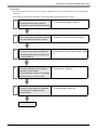
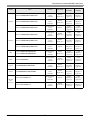
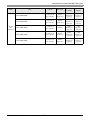
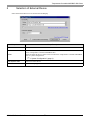
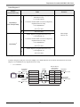
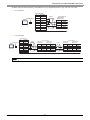
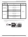
1
RKC Instrument Inc. Temperature Controller MODBUS SIO Driver 1 System Configuration....................................................................................................... 3 2 Selection of External Device ............................................................................................ 6 3 Example of Communication Setting ................................................................................. 7 4 Setup Items .................................................................................................................... 53 5 Cable Diagram ............................................................................................................... 58 6 Supported Device........................................................................................................... 83 7 Device Code and Address Code.................................................................................... 90 8 Error Messages.............................................................................................................. 92 1 Temperature Controller MODBUS SIO Driver Introduction This manual describes how to connect the Display (GP3000 series) and the External Device (target Temperature Controller). In this manual, the connection procedure will be described by following the below sections: 1 System Configuration This section shows the types of External Devices which can be connected and SIO type. ) "1 System Configuration" (page 3) 2 Selection of External Device Select a model (series) of the External Device to be connected and connection method. ) "2 Selection of External Device" (page 6) 3 Example of Communication Settings This section shows setting examples for communicating between the Display and the External Device. ) "3 Example of Communication Setting" (page 4 Setup Items This section describes communication setup items on the Display. Set communication settings of the Display with GP-Pro EX or in off-line mode. ) "4 Setup Items" (page 53) 5 Cable Diagram This section shows cables and adapters for connecting the Display and the External Device. ) "5 Cable Diagram" (page 58) Operation GP-Pro EX Device/PLC Connection Manual 2 7) Temperature Controller MODBUS SIO Driver 1 System Configuration The system configuration in the case when the External Device of RKC Instrument Inc. and the Display are connected is shown. Series CB FB400/ FB900 HA400/ HA900 Link I/F SIO Type Setting Example Cable Diagram CB100-*-5/Z-1021 CB400-*-5/Z-1021 CB500-*-5/Z-1021 CB700-*-5/Z-1021 CB900-*-5/Z-1021 Terminal block on the controller RS422/ 485(2 wire) Setting Example 1 (page 7) Cable Diagram 3 (page 62) FB900--*1/- FB400--*1/- Terminal block on the controller RS232C Setting Example 2 (page 9) Cable Diagram 6 (page 71) FB900--*4/- FB400--*4/- Terminal block on the controller RS422/ 485(4 wire) Setting Example 3 (page 11) Cable Diagram 7 (page 72) FB900--*5/- FB900--*X/- FB900--*Y/- FB400--*5/- FB400--*X/- FB400--*Y/- Terminal block on the controller RS422/ 485(2 wire) Setting Example 4 (page 13) Cable Diagram 3 (page 62) FB900--*W/- Terminal block on the controller RS232C Setting Example 2 (page 9) Cable Diagram 6 (page 71) FB400--*W/- Terminal block on the controller RS422/ 485(2 wire) Setting Example 4 (page 13) Cable Diagram 3 (page 62) HA900---*-6-// HA900---*-6-// HA901---*-6-// HA901---*-6-// HA400---*-6-// HA400---*-6-// HA401---*-6-// HA401---*-6-// Terminal block on the controller RS422/ 485(2 wire) Setting Example 5 (page 15) Cable Diagram 3 (page 62) HA900---*-8-// HA900---*-8-// HA901---*-8-// HA901---*-8-// HA400---*-8-// HA400---*-8-// HA401---*-8-// HA401---*-8-// Terminal block on the controller RS232C Setting Example 6 (page 17) Cable Diagram 6 (page 71) HA900---*-7-// HA901---*-7-// HA400---*-7-// HA401---*-7-// Terminal block on the controller RS422/ 485(4 wire) Setting Example 7 (page 19) Cable Diagram 7 (page 72) CPU continued to next page GP-Pro EX Device/PLC Connection Manual 3 Temperature Controller MODBUS SIO Driver Link I/F SIO Type Setting Example Cable Diagram MA900-4--*-6/ Terminal block on the controller RS422/ 485(2 wire) Setting Example 8 (page 21) Cable Diagram 3 (page 62) MA900-4--*-7/ Terminal block on the controller RS422/ 485(4 wire) Setting Example 9 (page 23) Cable Diagram 7 (page 72) MA900-4--*-8/ Terminal block on the controller RS232C Setting Example 10 (page 25) Cable Diagram 6 (page 71) MA901-8--*-6/ Terminal block on the controller RS422/ 485(2 wire) Setting Example 8 (page 21) Cable Diagram 3 (page 62) MA901-8--*-7/ Terminal block on the controller RS422/ 485(4 wire) Setting Example 9 (page 23) Cable Diagram 7 (page 72) MA901-8--*-8/ Terminal block on the controller RS232C Setting Example 10 (page 25) Cable Diagram 6 (page 71) SRV V-TIO-A--*---6 V-TIO-C--*---6 Terminal block on the controller RS422/ 485(2 wire) Setting Example 14 (page 33) Cable Diagram 3 (page 62) SRX X-TIO-A--* Terminal block on the controller RS422/ 485(2 wire) Setting Example 14 (page 33) Cable Diagram 3 (page 62) SA100 SA100--*-6/ Terminal block on the controller RS422/ 485(2 wire) Setting Example 6 (page 37) Cable Diagram 3 (page 62) SA200 SA200--*-6// Terminal block on the controller RS422/ 485(2 wire) Setting Example 6 (page 37) Cable Diagram 3 (page 62) H-PCP-A-1N-*Z-1021 Terminal block on the controller RS232C Setting Example 18 (page 41) Cable Diagram 1 (page 58) H-PCP-A-4N-*Z-1021 Terminal block on the controller RS422/ 485(4 wire) Setting Example 19 (page 43) Cable Diagram 2 (page 59) Series MA900 MA901 CPU SR Mini HG (H-PCP-A) continued to next page GP-Pro EX Device/PLC Connection Manual 4 Temperature Controller MODBUS SIO Driver Link I/F SIO Type Setting Example Cable Diagram H-PCP-J-4-D* Connector on the controller RS422/ 485(4 wire) Setting Example 20 (page 45) Cable Diagram 4 (page 65) H-PCP-J-5-D* Connector on the controller RS422/ 485(2 wire) Setting Example 21 (page 48) Cable Diagram 5 (page 68) H-PCP-J-1-D* Connector on the controller RS232C Setting Example 18 (page 41) Cable Diagram 1 (page 58) H-PCP-J-4-D* Connector on the controller RS422/ 485(4 wire) Setting Example 20 (page 45) Cable Diagram 8 (page 75) H-PCP-J-5-D* Connector on the controller RS422/ 485(2 wire) Setting Example 21 (page 48) Cable Diagram 9 (page 79) Series SR Mini HG (H-PCP-J) CPU GP-Pro EX Device/PLC Connection Manual 5 Temperature Controller MODBUS SIO Driver 2 Selection of External Device Select the External Device to be connected to the Display. Setup Items Maker Driver Setup Description Select the maker of the External Device to be connected. Select "RKC Instrument Inc.". Select a model (series) of the External Device to be connected and connection method. Select "Temperature Controller MODBUS SIO". Check the External Device which can be connected in "Temperature Controller MODBUS SIO" in system configuration. ) "1 System Configuration" (page 3) Use System Area Cannot use in this driver. Port Select the Display port to be connected to the External Device. GP-Pro EX Device/PLC Connection Manual 6 Temperature Controller MODBUS SIO Driver 3 Example of Communication Setting Examples of communication settings of the Display and the External Device, recommended by Digital Electronics Corp., are shown. 3.1 Setting Example 1 Settings of GP-Pro EX Communication Settings To display the setting screen, select [Device/PLC Settings] from [System setting window] in workspace. GP-Pro EX Device/PLC Connection Manual 7 Temperature Controller MODBUS SIO Driver Device Setting To display the setting screen, click ([Setting]) of the External Device you want to set from [Device-Specific Settings ] of [Device/PLC Settings ]. Settings of External Device Use the SET key, shift key, down key and up key on the front of the Temperature Controller for communication settings of the External Device. Please refer to the manual of the Temperature Controller for more details. Procedure 1. While pressing down the SET key, press the shift key to move from the PV/SV display mode to the communication setting mode. 2. Press the SET key to select the parameter. 3. Press the down/up keys to change the setting. 4. While pressing down the SET key, press the shift key to move from the communication setting mode to the PV/SV display mode. 5. To confirm the setting, restart the Temperature Controller. Setting Value Add 1 bPS 2 bIT 0 • Parameters to be set vary depending on the Temperature Controller. Please refer to the manual of the Temperature Controller for more details. GP-Pro EX Device/PLC Connection Manual 8 Temperature Controller MODBUS SIO Driver 3.2 Setting Example 2 Settings of GP-Pro EX Communication Settings To display the setting screen, select [Device/PLC Settings] from [System setting window] in workspace. GP-Pro EX Device/PLC Connection Manual 9 Temperature Controller MODBUS SIO Driver Device Setting To display the setting screen, click ([Setting]) of the External Device you want to set from [Device-Specific Settings ] of [Device/PLC Settings ]. Settings of External Device Use the SET key, shift key, down key and up key on the front of the Temperature Controller for communication settings of the External Device. Please refer to the manual of the Temperature Controller for more details. Procedure 1. While pressing down the SET key, press and hold the shift key to move from the PV/SV display mode to the engineering mode. 2. Press the up key several times to specify F60, and press the SET key. 3. Set 1 for CMP1. 4. While pressing down the SET key, press the shift key to move from the engineering mode to the PV/SV display mode. 5. While pressing down the SET key, press the shift key to move from the PV/SV display mode to the setup setting mode. 6. Press the SET key several times to select the parameter. 7. Press the down/up keys to change the setting. 8. While pressing down the SET key, press the shift key to move from the setup setting mode to the PV/SV display mode. 9. To confirm the setting, restart the Temperature Controller. Setting Value Add1 1 bPS1 9.6 bIT1 8n1 • Parameters to be set vary depending on the Temperature Controller. Please refer to the manual of the Temperature Controller for more details. GP-Pro EX Device/PLC Connection Manual 10 Temperature Controller MODBUS SIO Driver 3.3 Setting Example 3 Settings of GP-Pro EX Communication Settings To display the setting screen, select [Device/PLC Settings] from [System setting window] in workspace. GP-Pro EX Device/PLC Connection Manual 11 Temperature Controller MODBUS SIO Driver Device Setting To display the setting screen, click ([Setting]) of the External Device you want to set from [Device-Specific Settings ] of [Device/PLC Settings ]. Settings of External Device Use the SET key, shift key, down key and up key on the front of the Temperature Controller for communication settings of the External Device. Please refer to the manual of the Temperature Controller for more details. Procedure 1. While pressing down the SET key, press and hold the shift key to move from the PV/SV display mode to the engineering mode. 2. Press the up key several times to specify F60, and press the SET key. 3. Set 1 for CMP1. 4. While pressing down the SET key, press the shift key to move from the engineering mode to the PV/SV display mode. 5. While pressing down the SET key, press the shift key to move from the PV/SV display mode to the setup setting mode. 6. Press the SET key several times to select the parameter. 7. Press the down/up keys to change the setting. 8. While pressing down the SET key, press the shift key to move from the setup setting mode to the PV/SV display mode. 9. To confirm the setting, restart the Temperature Controller. Setting Value Add1 1 bPS1 9.6 bIT1 8n1 • Parameters to be set vary depending on the Temperature Controller. Please refer to the manual of the Temperature Controller for more details. GP-Pro EX Device/PLC Connection Manual 12 Temperature Controller MODBUS SIO Driver 3.4 Setting Example 4 Settings of GP-Pro EX Communication Settings To display the setting screen, select [Device/PLC Settings] from [System setting window] in workspace. GP-Pro EX Device/PLC Connection Manual 13 Temperature Controller MODBUS SIO Driver Device Setting To display the setting screen, click ([Setting]) of the External Device you want to set from [Device-Specific Settings ] of [Device/PLC Settings ]. Settings of External Device Use the SET key, shift key, down key and up key on the front of the Temperature Controller for communication settings of the External Device. Please refer to the manual of the Temperature Controller for more details. Procedure 1. While pressing down the SET key, press and hold the shift key to move from the PV/SV display mode to the engineering mode. 2. Press the up key several times to specify F60, and press the SET key. 3. Set 1 for CMP1. 4. While pressing down the SET key, press the shift key to move from the engineering mode to the PV/SV display mode. 5. While pressing down the SET key, press the shift key to move from the PV/SV display mode to the setup setting mode. 6. Press the SET key several times to select the parameter. 7. Press the down/up keys to change the setting. 8. While pressing down the SET key, press the shift key to move from the setup setting mode to the PV/SV display mode. 9. To confirm the setting, restart the Temperature Controller. Setting Value Add1 1 bPS1 9.6 bIT1 8n1 • Parameters to be set vary depending on the Temperature Controller. Please refer to the manual of the Temperature Controller for more details. GP-Pro EX Device/PLC Connection Manual 14 Temperature Controller MODBUS SIO Driver 3.5 Setting Example 5 Settings of GP-Pro EX Communication Settings To display the setting screen, select [Device/PLC Settings] from [System setting window] in workspace. GP-Pro EX Device/PLC Connection Manual 15 Temperature Controller MODBUS SIO Driver Device Setting To display the setting screen, click ([Setting]) of the External Device you want to set from [Device-Specific Settings ] of [Device/PLC Settings ]. Settings of External Device Use the SET key, shift key, down key and up key on the front of the Temperature Controller for communication settings of the External Device. Please refer to the manual of the Temperature Controller for more details. Procedure 1. While pressing down the SET key, press the shift key to move from the SV setting & monitor mode to the setup setting mode. 2. Press the SET key several times to select the parameter. 3. Press the down/up keys to change the setting. 4. While pressing down the SET key, press the shift key to move from the setup setting mode to the SV setting & monitor mode. 5. To confirm the setting, restart the Temperature Controller. Setting Value Add1 1 bPS1 9.6 bIT1 8n1 • Parameters to be set vary depending on the Temperature Controller. Please refer to the manual of the Temperature Controller for more details. GP-Pro EX Device/PLC Connection Manual 16 Temperature Controller MODBUS SIO Driver 3.6 Setting Example 6 Settings of GP-Pro EX Communication Settings To display the setting screen, select [Device/PLC Settings] from [System setting window] in workspace. GP-Pro EX Device/PLC Connection Manual 17 Temperature Controller MODBUS SIO Driver Device Setting To display the setting screen, click ([Setting]) of the External Device you want to set from [Device-Specific Settings ] of [Device/PLC Settings ]. Settings of External Device Use the SET key, shift key, down key and up key on the front of the Temperature Controller for communication settings of the External Device. Please refer to the manual of the Temperature Controller for more details. Procedure 1. While pressing down the SET key, press the shift key to move from the SV setting & monitor mode to the setup setting mode. 2. Press the SET key several times to select the parameter. 3. Press the down/up keys to change the setting. 4. While pressing down the SET key, press the shift key to move from the setup setting mode to the SV setting & monitor mode. 5. To confirm the setting, restart the Temperature Controller. Setting Value Add1 1 bPS1 9.6 bIT1 8n1 • Parameters to be set vary depending on the Temperature Controller. Please refer to the manual of the Temperature Controller for more details. GP-Pro EX Device/PLC Connection Manual 18 Temperature Controller MODBUS SIO Driver 3.7 Setting Example 7 Settings of GP-Pro EX Communication Settings To display the setting screen, select [Device/PLC Settings] from [System setting window] in workspace. GP-Pro EX Device/PLC Connection Manual 19 Temperature Controller MODBUS SIO Driver Device Setting To display the setting screen, click ([Setting]) of the External Device you want to set from [Device-Specific Settings ] of [Device/PLC Settings ]. Settings of External Device Use the SET key, shift key, down key and up key on the front of the Temperature Controller for communication settings of the External Device. Please refer to the manual of the Temperature Controller for more details. Procedure 1. While pressing down the SET key, press the shift key to move from the SV setting & monitor mode to the setup setting mode. 2. Press the SET key several times to select the parameter. 3. Press the down/up keys to change the setting. 4. While pressing down the SET key, press the shift key to move from the setup setting mode to the SV setting & monitor mode. 5. To confirm the setting, restart the Temperature Controller. Setting Value Add1 1 bPS1 9.6 bIT1 8n1 • Parameters to be set vary depending on the Temperature Controller. Please refer to the manual of the Temperature Controller for more details. GP-Pro EX Device/PLC Connection Manual 20 Temperature Controller MODBUS SIO Driver 3.8 Setting Example 8 Settings of GP-Pro EX Communication Settings To display the setting screen, select [Device/PLC Settings] from [System setting window] in workspace. GP-Pro EX Device/PLC Connection Manual 21 Temperature Controller MODBUS SIO Driver Device Setting To display the setting screen, click ([Setting]) of the External Device you want to set from [Device-Specific Settings ] of [Device/PLC Settings ]. Settings of External Device Use the SET key, shift key, down key and up key on the front of the Temperature Controller for communication settings of the External Device. Please refer to the manual of the Temperature Controller for more details. Procedure 1. While pressing down the SET key, press the <R/S key to move from the PV/SV monitor mode to the setup setting mode. 2. Press the SET key several times to select the parameter. 3. Press the down/up keys and the <R/S key to change the setting. 4. While pressing down the SET key, press the <R/S key to move from the setup setting mode to the PV/SV monitor mode. 5. To confirm the setting, restart the Temperature Controller. Setting Value Add 1 bPS 960 bIT 8n1 • Parameters to be set vary depending on the Temperature Controller. Please refer to the manual of the Temperature Controller for more details. GP-Pro EX Device/PLC Connection Manual 22 Temperature Controller MODBUS SIO Driver 3.9 Setting Example 9 Settings of GP-Pro EX Communication Settings To display the setting screen, select [Device/PLC Settings] from [System setting window] in workspace. GP-Pro EX Device/PLC Connection Manual 23 Temperature Controller MODBUS SIO Driver Device Setting To display the setting screen, click ([Setting]) of the External Device you want to set from [Device-Specific Settings ] of [Device/PLC Settings ]. Settings of External Device Use the SET key, shift key, down key and up key on the front of the Temperature Controller for communication settings of the External Device. Please refer to the manual of the Temperature Controller for more details. Procedure 1. While pressing down the SET key, press the <R/S key to move from the PV/SV monitor mode to the setup setting mode. 2. Press the SET key several times to select the parameter. 3. Press the down/up keys and the <R/S key to change the setting. 4. While pressing down the SET key, press the <R/S key to move from the setup setting mode to the PV/SV monitor mode. 5. To confirm the setting, restart the Temperature Controller. Setting Value Add 1 bPS 960 bIT 8n1 • Parameters to be set vary depending on the Temperature Controller. Please refer to the manual of the Temperature Controller for more details. GP-Pro EX Device/PLC Connection Manual 24 Temperature Controller MODBUS SIO Driver 3.10 Setting Example 10 Settings of GP-Pro EX Communication Settings To display the setting screen, select [Device/PLC Settings] from [System setting window] in workspace. GP-Pro EX Device/PLC Connection Manual 25 Temperature Controller MODBUS SIO Driver Device Setting To display the setting screen, click ([Setting]) of the External Device you want to set from [Device-Specific Settings ] of [Device/PLC Settings ]. Settings of External Device Use the SET key, shift key, down key and up key on the front of the Temperature Controller for communication settings of the External Device. Please refer to the manual of the Temperature Controller for more details. Procedure 1. While pressing down the SET key, press the <R/S key to move from the PV/SV monitor mode to the setup setting mode. 2. Press the SET key several times to select the parameter. 3. Press the down/up keys and the <R/S key to change the setting. 4. While pressing down the SET key, press the <R/S key to move from the setup setting mode to the PV/SV monitor mode. 5. To confirm the setting, restart the Temperature Controller. Setting Value Add 1 bPS 960 bIT 8n1 • Parameters to be set vary depending on the Temperature Controller. Please refer to the manual of the Temperature Controller for more details. GP-Pro EX Device/PLC Connection Manual 26 Temperature Controller MODBUS SIO Driver 3.11 Setting Example 11 Settings of GP-Pro EX Communication Settings To display the setting screen, select [Device/PLC Settings] from [System setting window] in workspace. GP-Pro EX Device/PLC Connection Manual 27 Temperature Controller MODBUS SIO Driver Device Setting To display the setting screen, click ([Setting]) of the External Device you want to set from [Device-Specific Settings ] of [Device/PLC Settings ]. Settings of External Device Use the SET key, shift key, down key and up key on the front of the Temperature Controller for communication settings of the External Device. Please refer to the manual of the Temperature Controller for more details. Procedure 1. While pressing down the SET key, press the <R/S key to move from the PV/SV monitor mode to the setup setting mode. 2. Press the SET key several times to select the parameter. 3. Press the down/up keys and the <R/S key to change the setting. 4. While pressing down the SET key, press the <R/S key to move from the setup setting mode to the PV/SV monitor mode. 5. To confirm the setting, restart the Temperature Controller. Setting Value Add 1 bPS 960 bIT 8n1 • Parameters to be set vary depending on the Temperature Controller. Please refer to the manual of the Temperature Controller for more details. GP-Pro EX Device/PLC Connection Manual 28 Temperature Controller MODBUS SIO Driver 3.12 Setting Example 12 Settings of GP-Pro EX Communication Settings To display the setting screen, select [Device/PLC Settings] from [System setting window] in workspace. GP-Pro EX Device/PLC Connection Manual 29 Temperature Controller MODBUS SIO Driver Device Setting To display the setting screen, click ([Setting]) of the External Device you want to set from [Device-Specific Settings ] of [Device/PLC Settings ]. Settings of External Device Use the SET key, shift key, down key and up key on the front of the Temperature Controller for communication settings of the External Device. Please refer to the manual of the Temperature Controller for more details. Procedure 1. While pressing down the SET key, press the <R/S key to move from the PV/SV monitor mode to the setup setting mode. 2. Press the SET key several times to select the parameter. 3. Press the down/up keys and the <R/S key to change the setting. 4. While pressing down the SET key, press the <R/S key to move from the setup setting mode to the PV/SV monitor mode. 5. To confirm the setting, restart the Temperature Controller. Setting Value Add 1 bPS 960 bIT 8n1 • Parameters to be set vary depending on the Temperature Controller. Please refer to the manual of the Temperature Controller for more details. GP-Pro EX Device/PLC Connection Manual 30 Temperature Controller MODBUS SIO Driver 3.13 Setting Example 13 Settings of GP-Pro EX Communication Settings To display the setting screen, select [Device/PLC Settings] from [System setting window] in workspace. GP-Pro EX Device/PLC Connection Manual 31 Temperature Controller MODBUS SIO Driver Device Setting To display the setting screen, click ([Setting]) of the External Device you want to set from [Device-Specific Settings ] of [Device/PLC Settings ]. Settings of External Device Use the SET key, shift key, down key and up key on the front of the Temperature Controller for communication settings of the External Device. Please refer to the manual of the Temperature Controller for more details. Procedure 1. While pressing down the SET key, press the <R/S key to move from the PV/SV monitor mode to the setup setting mode. 2. Press the SET key several times to select the parameter. 3. Press the down/up keys and the <R/S key to change the setting. 4. While pressing down the SET key, press the <R/S key to move from the setup setting mode to the PV/SV monitor mode. 5. To confirm the setting, restart the Temperature Controller. Setting Value Add 1 bPS 960 bIT 8n1 • Parameters to be set vary depending on the Temperature Controller. Please refer to the manual of the Temperature Controller for more details. GP-Pro EX Device/PLC Connection Manual 32 Temperature Controller MODBUS SIO Driver 3.14 Setting Example 14 Settings of GP-Pro EX Communication Settings To display the setting screen, select [Device/PLC Settings] from [System setting window] in workspace. GP-Pro EX Device/PLC Connection Manual 33 Temperature Controller MODBUS SIO Driver Device Setting To display the setting screen, click ([Setting]) of the External Device you want to set from [Device-Specific Settings ] of [Device/PLC Settings ]. Settings of External Device Use the address setting switch on the front of the Temperature Controller and the DIP switch inside the Temperature Controller for communication settings of the External Device. Please refer to the manual of the Temperature Controller for more details. Procedure 1. Use the address setting switch on the front of the Temperature Controller to set the module address for HOST link. The number added 1 to the set value becomes the module address. 2. Use the DIP switch inside the Temperature Controller to set the speed and the data bit configuration. Setting Value Address setting switch High digit setting 0 Low digit setting 0 DIP Switch DIP Switch Settings 1 ON 2 OFF 3 ON 4 OFF 5 OFF 6 ON 7 OFF 8 OFF Description Speed Data bit configuration Protocol selection Fixed • Parameters to be set vary depending on the Temperature Controller. Please refer to the manual of the Temperature Controller for more details. GP-Pro EX Device/PLC Connection Manual 34 Temperature Controller MODBUS SIO Driver 3.15 Setting Example 15 Settings of GP-Pro EX Communication Settings To display the setting screen, select [Device/PLC Settings] from [System setting window] in workspace. GP-Pro EX Device/PLC Connection Manual 35 Temperature Controller MODBUS SIO Driver Device Setting To display the setting screen, click ([Setting]) of the External Device you want to set from [Device-Specific Settings ] of [Device/PLC Settings ]. Settings of External Device Use the address setting switch on the front of the Temperature Controller and the DIP switch inside the Temperature Controller for communication settings of the External Device. Please refer to the manual of the Temperature Controller for more details. Procedure 1. Use the address setting switch on the front of the Temperature Controller to set the module address for HOST link. The number added 1 to the set value becomes the module address. 2. Use the DIP switch inside the Temperature Controller to set the speed and the data bit configuration. Setting Value Address setting switch High digit setting 0 Low digit setting 0 DIP Switch DIP Switch Settings 1 ON 2 OFF 3 ON 4 OFF 5 OFF Description Speed Data bit configuration 6 ON 7 OFF Fixed OFF Internal data bus Terminal resistance setting 8 Protocol selection • Parameters to be set vary depending on the Temperature Controller. Please refer to the manual of the Temperature Controller for more details. GP-Pro EX Device/PLC Connection Manual 36 Temperature Controller MODBUS SIO Driver 3.16 Setting Example 6 Settings of GP-Pro EX Communication Settings To display the setting screen, select [Device/PLC Settings] from [System setting window] in workspace. GP-Pro EX Device/PLC Connection Manual 37 Temperature Controller MODBUS SIO Driver Device Setting To display the setting screen, click ([Setting]) of the External Device you want to set from [Device-Specific Settings ] of [Device/PLC Settings ]. Settings of External Device Use the SET key, shift key, down key and up key on the front of the Temperature Controller for communication settings of the External Device. Please refer to the manual of the Temperature Controller for more details. Procedure 1. While pressing down the SET key, press the shift key to move from the PV/SV display mode to the communication setting mode. 2. Press the SET key to select the parameter. 3. Press the down/up keys to change the setting. 4. While pressing down the SET key, press the shift key to move from the communication setting mode to the PV/SV display mode. 5. To confirm the setting, restart the Temperature Controller. Setting Value Add 1 bPS 960 bIT 8n1 • Parameters to be set vary depending on the Temperature Controller. Please refer to the manual of the Temperature Controller for more details. GP-Pro EX Device/PLC Connection Manual 38 Temperature Controller MODBUS SIO Driver 3.17 Setting Example 17 Settings of GP-Pro EX Communication Settings To display the setting screen, select [Device/PLC Settings] from [System setting window] in workspace. GP-Pro EX Device/PLC Connection Manual 39 Temperature Controller MODBUS SIO Driver Device Setting To display the setting screen, click ([Setting]) of the External Device you want to set from [Device-Specific Settings ] of [Device/PLC Settings ]. Settings of External Device Use the SET key, shift key, down key and up key on the front of the Temperature Controller for communication settings of the External Device. Please refer to the manual of the Temperature Controller for more details. Procedure 1. While pressing down the SET key, press the shift key to move from the PV/SV display mode to the communication setting mode. 2. Press the SET key to select the parameter. 3. Press the down/up keys to change the setting. 4. While pressing down the SET key, press the shift key to move from the communication setting mode to the PV/SV display mode. 5. To confirm the setting, restart the Temperature Controller. Setting Value Add 1 bPS 960 bIT 8n1 • Parameters to be set vary depending on the Temperature Controller. Please refer to the manual of the Temperature Controller for more details. GP-Pro EX Device/PLC Connection Manual 40 Temperature Controller MODBUS SIO Driver 3.18 Setting Example 18 Settings of GP-Pro EX Communication Settings To display the setting screen, select [Device/PLC Settings] from [System setting window] in workspace. GP-Pro EX Device/PLC Connection Manual 41 Temperature Controller MODBUS SIO Driver Device Setting To display the setting screen, click ([Setting]) of the External Device you want to set from [Device-Specific Settings ] of [Device/PLC Settings ]. Settings of External Device Use the slave address setting switch on the front of the Temperature Controller and the DIP switch inside the Temperature Controller for communication settings of the External Device. Please refer to the manual of the Temperature Controller for more details. Procedure 1. Use the slave address setting switch on the front of the Temperature Controller to set the slave address for HOST link. The number added 1 to the set value becomes the slave address. 2. Remove the Temperature Controller from the mother block, and use the DIP switch inside the Temperature Controller to set the speed and the data configuration. Setting Value Slave address setting switch High digit setting 0 Low digit setting 0 DIP Switch DIP Switch Settings 1 ON 2 ON 3 ON 4 OFF Description Data configuration Speed • Parameters to be set vary depending on the Temperature Controller. Please refer to the manual of the Temperature Controller for more details. GP-Pro EX Device/PLC Connection Manual 42 Temperature Controller MODBUS SIO Driver 3.19 Setting Example 19 Settings of GP-Pro EX Communication Settings To display the setting screen, select [Device/PLC Settings] from [System setting window] in workspace. GP-Pro EX Device/PLC Connection Manual 43 Temperature Controller MODBUS SIO Driver Device Setting To display the setting screen, click ([Setting]) of the External Device you want to set from [Device-Specific Settings ] of [Device/PLC Settings ]. Settings of External Device Use the slave address setting switch on the front of the Temperature Controller and the DIP switch inside the Temperature Controller for communication settings of the External Device. Please refer to the manual of the Temperature Controller for more details. Procedure 1. Use the slave address setting switch on the front of the Temperature Controller to set the slave address for HOST link. The number added 1 to the set value becomes the slave address. 2. Remove the Temperature Controller from the mother block, and use the DIP switch inside the Temperature Controller to set the speed and the data configuration. Setting Value Slave address setting switch High digit setting 0 Low digit setting 0 DIP Switch DIP Switch Settings 1 ON 2 ON 3 ON 4 OFF Description Data configuration Speed • Parameters to be set vary depending on the Temperature Controller. Please refer to the manual of the Temperature Controller for more details. GP-Pro EX Device/PLC Connection Manual 44 Temperature Controller MODBUS SIO Driver 3.20 Setting Example 20 Settings of GP-Pro EX Communication Settings To display the setting screen, select [Device/PLC Settings] from [System setting window] in workspace. GP-Pro EX Device/PLC Connection Manual 45 Temperature Controller MODBUS SIO Driver Device Setting To display the setting screen, click ([Setting]) of the External Device you want to set from [Device-Specific Settings ] of [Device/PLC Settings ]. Settings of External Device Use the unit address setting switch on the front of the Temperature Controller and the DIP switch on the side of the Temperature Controller for communication settings of the External Device. Please refer to the manual of the Temperature Controller for more details. Procedure 1. Use the unit address setting switch on the front of the Temperature Controller to set the module address for HOST link. The number added 1 to the set value becomes the unit address. 2. Use the DIP switch on the side of the Temperature Controller to set the speed and the data configuration. Setting Value Unit address setting switch High digit setting 0 Low digit setting 0 DIP Switch COM.PORT1/COM.PORT2 setting switch SW2 Settings 1 OFF 2 OFF 3 OFF 4 OFF 5 ON 6 OFF 7 OFF 8 OFF Description Data bit configuration Speed Communication Protocol GP-Pro EX Device/PLC Connection Manual 46 Temperature Controller MODBUS SIO Driver COM.PORT3 setting switch SW3 Settings 1 OFF 2 OFF Description Data bit configuration 3 OFF 4 OFF 5 ON 6 OFF Initialization 7 OFF MODBUS mode selection 8 OFF Fixed Speed Communication Protocol • Parameters to be set vary depending on the Temperature Controller. Please refer to the manual of the Temperature Controller for more details. GP-Pro EX Device/PLC Connection Manual 47 Temperature Controller MODBUS SIO Driver 3.21 Setting Example 21 Settings of GP-Pro EX Communication Settings To display the setting screen, select [Device/PLC Settings] from [System setting window] in workspace. GP-Pro EX Device/PLC Connection Manual 48 Temperature Controller MODBUS SIO Driver Device Setting To display the setting screen, click ([Setting]) of the External Device you want to set from [Device-Specific Settings ] of [Device/PLC Settings ]. Settings of External Device Use the unit address setting switch in front of the Temperature Controller and the DIP switch on the side of the Temperature Controller for communication settings of the External Device. Please refer to the manual of the Temperature Controller for more details. Procedure 1. Use the unit address setting switch on the front of the Temperature Controller to set the module address for HOST link. The number added 1 to the set value becomes the unit address. 2. Use the DIP switch on the side of the Temperature Controller to set the speed and the data configuration. Setting Value Unit address setting switch High digit setting 0 Low digit setting 0 DIP Switch • COM.PORT1/COM.PORT2setting switch SW2 Settings 1 OFF 2 OFF 3 OFF 4 OFF 5 ON 6 OFF 7 OFF 8 OFF Description Data bit configuration Speed Communication Protocol GP-Pro EX Device/PLC Connection Manual 49 Temperature Controller MODBUS SIO Driver • COM.PORT3 setting switch SW3 Settings 1 OFF 2 OFF Description Data bit configuration 3 OFF 4 OFF 5 ON 6 OFF Initialization 7 OFF MODBUS mode selection 8 OFF Fixed Speed Communication Protocol • Parameters to be set vary depending on the Temperature Controller. Please refer to the manual of the Temperature Controller for more details. GP-Pro EX Device/PLC Connection Manual 50 Temperature Controller MODBUS SIO Driver 3.22 Setting Example 22 Settings of GP-Pro EX Communication Settings To display the setting screen, select [Device/PLC Settings] from [System setting window] in workspace. GP-Pro EX Device/PLC Connection Manual 51 Temperature Controller MODBUS SIO Driver Device Setting To display the setting screen, click ([Setting]) of the External Device you want to set from [Device-Specific Settings ] of [Device/PLC Settings ]. Settings of External Device Use the unit address setting switch in front of the Temperature Controller and the DIP switch on the side of the Temperature Controller for communication settings of the External Device. Please refer to the manual of the Temperature Controller for more details. Procedure 1. Use the unit address setting switch on the front of the Temperature Controller to set the module address for HOST link. The number added 1 to the set value becomes the unit address. 2. Use the DIP switch on the side of the Temperature Controller to set the speed and the data configuration. Setting Value Unit address setting switch High digit setting 0 Low digit setting 0 DIP Switch • COM.PORT3 setting switch SW3 Settings 1 OFF 2 OFF Description Data bit configuration 3 OFF 4 OFF 5 ON 6 OFF Initialization 7 OFF MODBUS mode selection 8 OFF Fixed Speed Communication Protocol • Parameters to be set vary depending on the Temperature Controller. Please refer to the manual of the Temperature Controller for more details. GP-Pro EX Device/PLC Connection Manual 52 Temperature Controller MODBUS SIO Driver 4 Setup Items Set communication settings of the Display with GP-Pro Ex or in off-line mode of the Display. The setting of each parameter must be identical to that of External Device. )"3 Example of Communication Setting" (page 7) 4.1 Setup Items in GP-Pro EX Communication Settings To display the setting screen, select [Device/PLC Settings] from [System setting window] in workspace. Setup Items Setup Description SIO Type Select the SIO type to communicate with the External Device. Speed Select speed between the External Device and the Display. Data Length Select data length. Parity Select how to check parity. Stop Bit Select stop bit length. Flow Control The communication control method to prevent overflow of transmission and reception data is displayed. Timeout Use an integer from 1 to 127 to enter the time (s) for which the Display waits for the response from the External Device. Retry In case of no response from the External Device, use an integer from 0 to 255 to enter how many times the Display retransmits the command. continued to next page GP-Pro EX Device/PLC Connection Manual 53 Temperature Controller MODBUS SIO Driver Setup Items Setup Description Wait To Send Use an integer from 0 to 255 to enter standby time (ms) for the Display from receiving packets to transmitting next commands. RI/VCC Switches RI/VCC of the 9th pin. Device Setting To display the setting screen, click ([Setting]) of the External Device you want to set from [Device-Specific Settings ] of [Device/PLC Settings ]. When you connect multiple External Device, click from [Device-Specific Settings] of [ Device/PLC Settings] to add another External Device. Setup Items Setup Description Series Select a model of the External Device. Slave Address Enter the Slave Address of the External Device. GP-Pro EX Device/PLC Connection Manual 54 Temperature Controller MODBUS SIO Driver 4.2 Setup Items in Off-Line Mode • Please refer to GP3000 Series User's Manual for more information on how to enter off-line mode or about operation. Cf. GP3000 Series User's Manual "Chapter 4 Setting" Communication Settings To display the setting screen, touch [Device/PLC Settings] from [Peripheral Equipment Settings] in the off-line mode. Touch the External Device you want to set from the displayed list. Setup Items Setup Description SIO Type Select the SIO type to communicate with the External Device. Speed Select speed between the External Device and the Display. Data Length Select data length. Parity Select how to check parity. Stop Bit Select stop bit length. Flow Control The communication control method to prevent overflow of transmission and reception data is displayed. Timeout Use an integer from 1 to 127 to enter the time (s) for which the Display waits for the response from the External Device. Retry In case of no response from the External Device, use an integer from 0 to 255 to enter how many times the Display retransmits the command. Wait To Send Use an integer from 0 to 255 to enter standby time (ms) for the Display from receiving packets to transmitting next commands. GP-Pro EX Device/PLC Connection Manual 55 Temperature Controller MODBUS SIO Driver Device Setting To display the setting screen, touch [Device/PLC Settings] from [Peripheral Equipment Settings]. Touch the External Device you want to set from the displayed list, and touch [Device Settings]. Setup Items Setup Description Device name Select the External Device to set. Device name is a title of the External Device set with GPPro EX.(Default [PLC1]) Series Displays a model of the External Device. Slave Address Enter the slave address of the External Device, using 1 to 99. GP-Pro EX Device/PLC Connection Manual 56 Temperature Controller MODBUS SIO Driver Option To display the setting screen, touch [Device/PLC Settings] from [Peripheral Settings]. Touch the External Device you want to set from the displayed list, and touch [Option]. Setup Items RI/VCC Setup Description Switches RI/VCC of the 9th pin. GP-Pro EX Device/PLC Connection Manual 57 Temperature Controller MODBUS SIO Driver 5 Cable Diagram The cable diagram shown below may be different from the cable diagram recommended by RKC Instrument Inc. Please be assured there is no operational problem in applying the cable diagram shown in this manual. • The FG pin of the main body of the External Device must be D-class grounded. Please refer to the manual of • SG and FG are connected inside the Display. When connecting SG to the External Device, design the system the External Device for more details. not to form short-circuit loop. • When using RS422/485 (2 wire) or RS422/485 (4 wire) for connection, you can connect maximum 16 units of Temperature Controller. Note that you can connect maximum 15 units of Temperature Controller when using RS422/485 (4 wire) to connect the FB400/900 Series. Cable Diagram 1 Display (Connection Port) Cable GP(COM1) Remarks Your own cable D-Sub 9 Pin (socket) Display Cable length: 10m or less Shield External Device Modular 6 Pin Pin Signal name Pin Signal name 2 RD(RXD) 2 SD 3 SD(TXD) 4 RD 4 ER(DTR) 3 SG 5 SG 6 Shield 6 DR(DSR) 7 RS(RTS) 8 CS(CTS) GP-Pro EX Device/PLC Connection Manual 58 Temperature Controller MODBUS SIO Driver Cable Diagram 2 Display (Connection Port) GP(COM1)*1 AGP-3302(COM2) Cable A COM port conversion adapter by Digital Electronics Corp. CA3-ADPCOM-01 + Connector terminal block conversion adapter by Digital Electronics Corp. CA3-ADPTRM-01 + Your own cable B Your own cable C Online adapter by Digital Electronics Corp. CA4-ADPONL-01 + Connector terminal block conversion adapter by Digital Electronics Corp. CA3-ADPTRM-01 + Your own cable D Online adapter by Digital Electronics Corp. CA4-ADPONL-01 + Your own cable GP(COM2)*1 *1 Remarks Cable length: 500m or less Except AGP-3302 Series A) When using the COM port conversion adapter (CA3-ADPCOM-01), the connector terminal block conversion adapter (CA3-ADPTRM-01) by Digital Electronics Corp. • 1:1 Connection Display Termination resistance 120Ω + 10% or less CA3-ADPCOM-01 CA3-ADPTRM-01 Termination resistance 120Ω + 10% or less Shield Signal name External Device COM.PORT1 Modular 6 Pin Pin Signal name T(B) RDA 4 RDB 5 T(A) SDA 2 R(B) SDB 1 R(A) SG 3 SG TERM 6 Shield Your own cable GP-Pro EX Device/PLC Connection Manual 59 Termination resistance 120Ω + 10% or less Termination resistance 120Ω + 10% or less Temperature Controller MODBUS SIO Driver • Display 1: n connection Termination resistance 120Ω + 10% or less CA3-ADPCOM-01 CA3-ADPTRM-01 Termination resistance 120Ω + 10% or less External Device COM.PORT2 COM.PORT1 Modular 6 Pin Modular 6 Pin Shield Signal name Shield External Device COM.PORT2 COM.PORT1 Modular 6 Pin Modular 6 Pin Pin Signal name Pin Signal name Pin Signal name Pin Signal name RDA 4 T(B) 4 T(B) 4 T(B) 4 T(B) RDB 5 T(A) 5 T(A) 5 T(A) 5 T(A) SDA 2 R(B) 2 R(B) 2 R(B) 2 R(B) SDB 1 R(A) 1 R(A) 1 R(A) 1 R(A) SG 3 SG 3 SG 3 SG 3 SG TERM 6 Shield 6 Shield 6 Shield 6 Shield Termination resistance 120Ω + 10% or less Termination resistance 120Ω + 10% or less Your own cable B) When using your own cable • 1:1 Connection Termination resistance 120Ω + 10% or less Display Termination resistance 120Ω + 10% or less D-Sub 9 Pin (socket) Shield Pin Signal name 1 RDA 4 2 RDB 5 T(A) 3 SDA 2 R(B) 7 SDB 1 R(A) 5 SG 3 SG 4 ERA 6 Shield 8 CSA 9 ERB 6 CSB T(B) Termination resistance 120Ω + 10% or less Termination resistance 120Ω + 10% or less FG Shell • External Device COM.PORT1 Modular 6 Pin Pin Signal name 1:n Connection Termination D-Sub 9 Pin (socket) resistance Pin Signal name 120Ω + 10% or less 1 RDA Display RDB 2 Termination resistance 120Ω + 10% or less Shield External Device COM.PORT2 COM.PORT1 Modular 6 Pin Modular 6 Pin Shield External Device COM.PORT2 COM.PORT1 Modular 6 Pin Modular 6 Pin Pin Pin Signal name Signal name Pin Signal name Pin Signal name 4 T(B) 4 T(B) 4 T(B) 4 5 T(A) 5 T(A) 5 T(A) 5 T(A) T(B) 3 SDA 2 R(B) 2 R(B) 2 R(B) 2 R(B) 7 SDB 1 R(A) 1 R(A) 1 R(A) 1 R(A) 5 SG 3 SG 3 SG 3 SG 3 SG 4 ERA 6 Shield 6 Shield 6 Shield 6 Shield 8 CSA 9 ERB 6 CSB Shell Termination resistance 120Ω + 10% o Terminatio resistance 120Ω + 10% FG C) When using the online adapter (CA4-ADPONL-01), the connector terminal block conversion adapter (CA3ADPTRM-01) by Digital Electronics Corp. • 1:1 Connection Display Termination resistance 120Ω + 10% or less CA4-ADPONL-01 CA3-ADPTRM-01 Termination resistance 120Ω + 10% or less GP-Pro EX Device/PLC Connection Manual Shield Signal name External Device COM.PORT1 Modular 6 Pin Pin Signal name RDA 4 RDB 5 T(A) SDA 2 R(B) SDB 1 R(A) SG 3 SG TERM 6 Shield 60 Termination resistance 120Ω + 10% or less T(B) Termination resistance 120Ω + 10% or less Temperature Controller MODBUS SIO Driver • Display 1:n Connection Termination resistance 120Ω + 10% or less CA4-ADPONL-01 CA3-ADPTRM-01 Termination resistance 120Ω + 10% or less Shield Signal name External Device COM.PORT2 COM.PORT1 Modular 6 Pin Modular 6 Pin Pin Pin Signal name Signal name RDA 4 RDB SDA External Device COM.PORT1 COM.PORT2 Modular 6 Pin Modular 6 Pin Pin Pin Signal name Signal name Shield T(B) 4 5 T(A) 2 R(B) R(A) 1 SG 3 Shield 6 T(B) 4 5 T(A) 2 R(B) SDB 1 SG 3 TERM 6 T(B) 4 5 T(A) 5 T(A) 2 R(B) 2 R(B) R(A) 1 R(A) 1 R(A) SG 3 SG 3 SG Shield 6 Shield 6 Shield T(B) Termination resistance 120Ω + 10% or les Termination resistance 120Ω + 10% or les Your own cable D) When using the online adapter (CA4-ADPONL-01) by Digital Electronics Corp. and your own cable • 1:1 Connection External Device COM.PORT1 Modular 6 Pin Pin Signal name D-Sub 9 Pin (plug) Display Termination resistance 120Ω + 10% or less CA4-ADPONL-01 Termination resistance 120Ω + 10% or less Pin Signal name Shield 1 TERMRX 2 RDA 4 7 RDB 5 T(A) 3 SDA 2 R(B) 8 SDB 1 R(A) 5 SG 3 SG 9 TERMTX 6 Shield Shell FG T(B) Termination resistance 120Ω + 10% or less Termination resistance 120Ω + 10% or less Your own cable • 1:n Connection Termination resistance 120Ω + 10% or less CA4-ADPONL-01 Display Termination resistance 120Ω + 10% or less D-Sub 9 Pin (plug) Pin Signal name Shield External Device COM.PORT2 COM.PORT1 Modular 6 Pin Modular 6 Pin Pin Pin Signal name Signal name Shield External Device COM.PORT2 COM.PORT1 Modular 6 Pin Modular 6 Pin Termination resistance Pin Pin Signal name Signal name 120Ω + 10% or less 4 T(B) 4 T(B) 1 TERMRX 2 RDA 4 T(B) 4 7 RDB 5 T(A) 5 T(A) 5 T(A) 5 T(A) 3 SDA 2 R(B) 2 R(B) 2 R(B) 2 R(B) 8 SDB 1 R(A) 1 R(A) 1 R(A) 1 R(A) 5 SG 3 SG 3 SG 3 SG 3 SG 9 TERMTX 6 Shield 6 Shield 6 Shield 6 Shield Shell FG T(B) Your own cable GP-Pro EX Device/PLC Connection Manual 61 Termination resistance 120Ω + 10% or less Temperature Controller MODBUS SIO Driver Cable Diagram 3 Display (Connection Port) Cable GP(COM1)*1 AGP-3302(COM2) A COM port conversion adapter by Digital Electronics Corp. CA3-ADPCOM-01 + Connector terminal block conversion adapter by Digital Electronics Corp. CA3-ADPTRM-01 + Your own cable B Your own cable C Online adapter by Digital Electronics Corp. CA4-ADPONL-01 + Connector terminal block conversion adapter by Digital Electronics Corp. CA3-ADPTRM-01 + Your own cable D Online adapter by Digital Electronics Corp. CA4-ADPONL-01 + Your own cable GP(COM2)*1 *1 Remarks Cable length: 600m or less Except AGP-3302 Series A) When using the COM port conversion adapter (CA3-ADPCOM-01) and the connector terminal block conversion adapter (CA3-ADPTRM-01) by Digital Electronics Corp. • 1:1 Connection Termination resistance 120 Ω (1/2W) Display CA3-ADPCOM-01 CA3-ADPTRM-01 Signal name Shield RDA External Device Terminal block RDB Signal name SDA T/R(B) SDB T/R(A) SG SG Termination resistance 120 Ω (1/2W) FG Your own cable • 1: n connection Termination resistance 120 Ω (1/2W) Display CA3-ADPCOM-01 CA3-ADPTRM-01 Signal name Shield RDA External Device Terminal block Shield External Device Terminal block RDB Signal name Signal name SDA T/R(B) T/R(B) SDB T/R(A) T/R(A) SG SG SG FG Your own cable GP-Pro EX Device/PLC Connection Manual 62 Termination resistance 120 Ω (1/2W) Temperature Controller MODBUS SIO Driver B) When using your own cable • 1:1 Connection D-Sub 9 Pin (socket) Termination resistance 120 Ω (1/2W) Display Pin Signal name 1 RDA External Device Terminal block 2 RDB Signal name 3 SDA T/R(B) 7 SDB T/R(A) 5 SG SG 4 ERA 8 CSA 9 ERB 6 CSB Termination resistance 120 Ω (1/2W) FG Shell • Shield 1:n Connection Termination resistance 120 Ω (1/2W) Display D-Sub 9 Pin (socket) Pin Signal name 1 RDA External Device Terminal block 2 RDB Signal name Signal name 3 SDA T/R(B) T/R(B) 7 SDB T/R(A) T/R(A) 5 SG SG SG 4 ERA 8 CSA 9 ERB 6 CSB Shield External Device Terminal block Shield Termination resistance 120 Ω (1/2W) FG Shell C) When using the online adapter (CA4-ADPONL-01), the connector terminal block conversion adapter (CA3ADPTRM-01) by Digital Electronics Corp. • 1:1 Connection Termination resistance 120 Ω (1/2W) Display CA4-ADPONL-01 CA3-ADPTRM-01 Signal name Shield RDA External Device Terminal block RDB Signal name SDA T/R(B) SDB T/R(A) SG SG Termination resistance 120 Ω (1/2W) FG Your own cable • 1:n Connection Termination resistance 120 Ω (1/2W) Display CA4-ADPONL-01 CA3-ADPTRM-01 Signal name Shield RDA External Device Terminal block RDB Signal name Signal name SDA T/R(B) T/R(B) SDB T/R(A) T/R(A) SG SG SG FG Your own cable GP-Pro EX Device/PLC Connection Manual 63 Shield External Device Terminal block Termination resistance 120 Ω (1/2W) Temperature Controller MODBUS SIO Driver D) When using the online adapter (CA4-ADPONL-01) by Digital Electronics Corp. and your own cable • 1:1 Connection D-Sub 9 Pin (plug) Pin Signal name 1 TERMRX 2 RDA External Device Terminal block 7 RDB Signal name 3 SDA T/R(B) 8 SDB T/R(A) 5 SG SG 9 TERMTX Shell FG Termination resistance 120 Ω (1/2W) CA4-ADPONL-01 Display Shield Termination resistance 120 Ω (1/2W) Your own cable • 1:n Connection D-Sub 9 Pin (plug) Termination resistance 120 Ω (1/2W) CA4-ADPONL-01 Display Pin Signal name 1 TERMRX 2 RDA External Device Terminal block 7 RDB Signal name Signal name 3 SDA T/R(B) T/R(B) 8 SDB T/R(A) T/R(A) 5 SG SG SG 9 TERMTX Shell FG Shield Your own cable GP-Pro EX Device/PLC Connection Manual 64 Shield External Device Terminal block Termination resistance 120 Ω (1/2W) Temperature Controller MODBUS SIO Driver Cable Diagram 4 Display (Connection Port) Cable GP(COM1)*1 AGP-3302(COM2) A COM port conversion adapter by Digital Electronics Corp. CA3-ADPCOM-01 + Connector terminal block conversion adapter by Digital Electronics Corp. CA3-ADPTRM-01 + Your own cable B Your own cable C Online adapter by Digital Electronics Corp. CA4-ADPONL-01 + Connector terminal block conversion adapter by Digital Electronics Corp. CA3-ADPTRM-01 + Your own cable D Online adapter by Digital Electronics Corp. CA4-ADPONL-01 + Your own cable GP(COM2)*1 *1 Remarks Cable length: 5m or less Except AGP-3302 Series A) When using the COM port conversion adapter (CA3-ADPCOM-01) and the connector terminal block conversion adapter (CA3-ADPTRM-01) by Digital Electronics Corp. • 1:1 Connection Shield Pin Signal name RDA 4 T(B) RDB 5 T(A) SDA 2 R(B) SDB 1 R(A) SG 3 SG FG 6 Shield Signal name Display CA3-ADPCOM-01 CA3-ADPTRM-01 External Device COM.PORT1 Modular 6 Pin Your own cable • 1: n connection Shield Signal name Display CA3-ADPCOM-01 CA3-ADPTRM-01 External Device COM.PORT2 COM.PORT1 Modular 6 Pin Modular 6 Pin Pin Signal name Pin Signal name Shield External Device COM.PORT2 COM.PORT1 Modular 6 Pin Modular 6 Pin Pin Signal name Pin Signal name RDA 4 T(B) 4 T(B) 4 T(B) 4 RDB 5 T(A) 5 T(A) 5 T(A) 5 T(A) SDA 2 R(B) 2 R(B) 2 R(B) 2 R(B) SDB 1 R(A) 1 R(A) 1 R(A) 1 R(A) SG 3 SG 3 SG 3 SG 3 SG FG 6 Shield 6 Shield 6 Shield 6 Shield Your own cable • Termination resistance is not necessary. GP-Pro EX Device/PLC Connection Manual 65 T(B) Temperature Controller MODBUS SIO Driver B) When using your own cable • 1:1 Connection D-Sub 9 Pin (socket) Display Pin Signal name Pin Signal name 1 RDA 4 T(B) 2 RDB 5 T(A) 3 SDA 2 R(B) 7 SDB 1 R(A) 5 SG 3 SG 4 ERA 6 Shield 8 CSA 9 ERB 6 CSB Shell • Shield External Device COM.PORT1 Modular 6 Pin FG 1:n Connection Shield D-Sub 9 Pin (socket) Display External Device COM.PORT2 COM.PORT1 Modular 6 Pin Modular 6 Pin Pin Signal name Pin Signal name Shield External Device COM.PORT2 COM.PORT1 Modular 6 Pin Modular 6 Pin Pin Signal name Pin Signal name Pin Signal name 1 RDA 4 T(B) 4 T(B) 4 T(B) 4 2 RDB 5 T(A) 5 T(A) 5 T(A) 5 T(A) 3 SDA 2 R(B) 2 R(B) 2 R(B) 2 R(B) 7 SDB 1 R(A) 1 R(A) 1 R(A) 1 R(A) 5 SG 3 SG 3 SG 3 SG 3 SG 4 ERA 6 Shield 6 Shield 6 Shield 6 Shield 8 CSA 9 ERB 6 CSB Shell T(B) FG • Termination resistance is not necessary. C) When using the online adapter (CA4-ADPONL-01), the connector terminal block conversion adapter (CA3ADPTRM-01) by Digital Electronics Corp. • 1:1 Connection Shield Display CA4-ADPONL-01 CA3-ADPTRM-01 Signal name Pin Signal name RDA 4 T(B) RDB 5 T(A) SDA 2 R(B) SDB 1 R(A) SG 3 SG FG 6 Shield Your own cable GP-Pro EX Device/PLC Connection Manual External Device COM.PORT1 Modular 6 Pin 66 Temperature Controller MODBUS SIO Driver • 1:n Connection External Device COM.PORT2 COM.PORT1 Modular 6 Pin Modular 6 Pin Pin Signal name Pin Signal name Shield Signal name Display CA4-ADPONL-01 CA3-ADPTRM-01 External Device COM.PORT2 COM.PORT1 Modular 6 Pin Modular 6 Pin Pin Signal name Pin Signal name Shield RDA 4 T(B) 4 T(B) 4 T(B) 4 RDB 5 T(A) 5 T(A) 5 T(A) 5 T(A) SDA 2 R(B) 2 R(B) 2 R(B) 2 R(B) SDB 1 R(A) 1 R(A) 1 R(A) 1 R(A) SG 3 SG 3 SG 3 SG 3 SG FG 6 Shield 6 Shield 6 Shield 6 Shield T(B) Your own cable • Termination resistance is not necessary. D) When using the online adapter (CA4-ADPONL-01) by Digital Electronics Corp. and your own cable • 1:1 Connection D-Sub 9 Pin (plug) CA4-ADPONL-01 Display External Device COM.PORT1 Modular 6 Pin Pin Signal name 1 TERMRX 2 RDA 4 7 RDB 5 T(A) 3 SDA 2 R(B) 8 SDB 1 R(A) 5 SG 3 SG 9 TERMTX 6 Shield Shell FG Shield Pin Signal name T(B) Your own cable • 1:n Connection D-Sub 9 Pin (plug) CA4-ADPONL-01 Display External Device COM.PORT2 COM.PORT1 Modular 6 Pin Modular 6 Pin Pin Signal name Pin Signal name Shield External Device COM.PORT2 COM.PORT1 Modular 6 Pin Modular 6 Pin Pin Signal name Pin Signal name Pin Signal name 1 TERMRX 2 RDA 4 T(B) 4 T(B) 4 T(B) 4 7 RDB 5 T(A) 5 T(A) 5 T(A) 5 T(A) 3 SDA 2 R(B) 2 R(B) 2 R(B) 2 R(B) 8 SDB 1 R(A) 1 R(A) 1 R(A) 1 R(A) 5 SG 3 SG 3 SG 3 SG 3 SG 9 TERMTX 6 Shield 6 Shield 6 Shield 6 Shield Shell Shield FG Your own cable • Termination resistance is not necessary. GP-Pro EX Device/PLC Connection Manual 67 T(B) Temperature Controller MODBUS SIO Driver Cable Diagram 5 Display (Connection Port) Cable GP(COM1)*1 AGP-3302(COM2) A COM port conversion adapter by Digital Electronics Corp. CA3-ADPCOM-01 + Connector terminal block conversion adapter by Digital Electronics Corp. CA3-ADPTRM-01 + Your own cable B Your own cable C Online adapter by Digital Electronics Corp. CA4-ADPONL-01 + Connector terminal block conversion adapter by Digital Electronics Corp. CA3-ADPTRM-01 + Your own cable D Online adapter by Digital Electronics Corp. CA4-ADPONL-01 + Your own cable GP(COM2)*1 *1 Remarks Cable length: 5m or less Except AGP-3302 Series A) When using the COM port conversion adapter (CA3-ADPCOM-01) and the connector terminal block conversion adapter (CA3-ADPTRM-01) by Digital Electronics Corp. • 1:1 Connection RDA External Device COM.PORT1 Modular 6 Pin Signal name Display CA3-ADPCOM-01 CA3-ADPTRM-01 Shield RDB Pin Signal name SDA 2 T/R(B) SDB 1 T/R(A) SG 3 SG FG 6 Shield Your own cable • 1: n connection Signal name Shield RDA Display CA3-ADPCOM-01 CA3-ADPTRM-01 External Device COM.PORT2 COM.PORT1 Modular 6 Pin Modular 6 Pin Shield External Device COM.PORT2 COM.PORT1 Modular 6 Pin Modular 6 Pin RDB Pin Signal name Pin Signal name Signal name Pin Signal name SDA 2 T/R(B) 2 T/R(B) 2 T/R(B) 2 T/R(B) SDB 1 T/R(A) 1 T/R(A) 1 T/R(A) 1 T/R(A) SG 3 SG 3 SG 3 SG 3 SG FG 6 Shield 6 Shield 6 6 Shield Your own cable • Termination resistance is not necessary. GP-Pro EX Device/PLC Connection Manual 68 Pin Shield Temperature Controller MODBUS SIO Driver B) When using your own cable • 1:1 Connection D-Sub 9 Pin (socket) Pin Signal name 1 RDA External Device COM.PORT1 Modular 6 Pin 2 RDB Pin Signal name 3 SDA 2 T/R(B) 7 SDB 1 T/R(A) 5 SG 3 SG 4 ERA 6 Shield 8 CSA 9 ERB 6 CSB Display FG Shell • Shield 1:n Connection D-Sub 9 Pin (socket) Display Pin Signal name 1 RDA 2 RDB External Device COM.PORT2 COM.PORT1 Modular 6 Pin Modular 6 Pin Pin Signal name Pin Signal name 3 SDA 2 T/R(B) 2 T/R(B) 2 T/R(B) 2 T/R(B) 7 SDB 1 T/R(A) 1 T/R(A) 1 T/R(A) 1 T/R(A) 5 SG 3 SG 3 SG 3 SG 3 SG 4 ERA 6 Shield 6 Shield 6 Shield 6 Shield 8 CSA 9 ERB 6 CSB Shield External Device COM.PORT2 COM.PORT1 Modular 6 Pin Modular 6 Pin Pin Signal name Pin Signal name Shield FG Shell • Termination resistance is not necessary. C) When using the online adapter (CA4-ADPONL-01), the connector terminal block conversion adapter (CA3ADPTRM-01) by Digital Electronics Corp. • 1:1 Connection RDA External Device COM.PORT1 Modular 6 Pin Signal name Display CA4-ADPONL-01 CA3-ADPTRM-01 Shield RDB Pin Signal name SDA 2 T/R(B) SDB 1 T/R(A) SG 3 SG FG 6 Shield Your own cable • 1:n Connection Signal name Display Shield RDA CA4-ADPONL-01 CA3-ADPTRM-01 External Device COM.PORT2 COM.PORT1 Modular 6 Pin Modular 6 Pin Shield External Device COM.PORT2 COM.PORT1 Modular 6 Pin Modular 6 Pin RDB Pin Signal name Pin Signal name Pin Signal name 2 T/R(B) 2 T/R(B) Pin 2 Signal name SDA T/R(B) 2 T/R(B) SDB 1 T/R(A) 1 T/R(A) 1 T/R(A) 1 T/R(A) SG 3 SG 3 SG 3 SG 3 SG FG 6 Shield 6 Shield 6 Shield 6 Shield Your own cable • Termination resistance is not necessary. GP-Pro EX Device/PLC Connection Manual 69 Temperature Controller MODBUS SIO Driver D) When using the online adapter (CA4-ADPONL-01) by Digital Electronics Corp. and your own cable • 1:1 Connection D-Sub 9 Pin (plug) CA4-ADPONL-01 Display Pin Signal name 1 TERMRX 2 RDA 7 RDB 3 SDA 2 T/R(B) 8 SDB 1 T/R(A) 5 SG 3 SG 9 TERMTX 6 Shield Shell FG Shield External Device COM.PORT1 Modular 6 Pin Pin Signal name Your own cable • 1:n Connection D-Sub 9 Pin (plug) Pin CA4-ADPONL-01 Display Signal name External Device COM.PORT1 COM.PORT2 Modular 6 Pin Modular 6 Pin Pin Pin Signal name Signal name External Device COM.PORT1 COM.PORT2 Modular 6 Pin Modular 6 Pin Pin Pin Signal name Signal name 1 TERMRX 2 RDA 7 RDB 3 SDA 2 T/R(B) 2 T/R(B) 2 T/R(B) 2 T/R(B) 8 SDB 1 T/R(A) 1 T/R(A) 1 T/R(A) 1 T/R(A) 5 SG 3 SG 3 SG 3 SG 3 SG 9 TERMTX 6 Shield 6 Shield 6 Shield 6 Shield Shell FG Shield Your own cable • Termination resistance is not necessary. GP-Pro EX Device/PLC Connection Manual 70 Shield Temperature Controller MODBUS SIO Driver Cable Diagram 6 Display (Connection Port) GP(COM1) Cable Remarks Your own cable Cable length: 10m or less When using your own cable D-Sub 9 Pin (socket) Shield External Device Terminal block Pin Signal name Signal name 2 RD(RXD) SD 3 SD(TXD) RD 5 SG SG 4 ER(DTR) 6 DR(DSR) Display 7 RS(RTS) 8 CS(CTS) Shell FG GP-Pro EX Device/PLC Connection Manual 71 Temperature Controller MODBUS SIO Driver Cable Diagram 7 Display (Connection Port) Cable GP(COM1)*1 AGP-3302(COM2) A COM port conversion adapter by Digital Electronics Corp. CA3-ADPCOM-01 + Connector terminal block conversion adapter by Digital Electronics Corp. CA3-ADPTRM-01 + Your own cable B Your own cable C Online adapter by Digital Electronics Corp. CA4-ADPONL-01 + Connector terminal block conversion adapter by Digital Electronics Corp. CA3-ADPTRM-01 + Your own cable D Online adapter by Digital Electronics Corp. CA4-ADPONL-01 + Your own cable GP(COM2)*1 *1 Remarks Cable length: 600m or less Except AGP-3302 Series A) When using the COM port conversion adapter (CA3-ADPCOM-01) and the connector terminal block conversion adapter (CA3-ADPTRM-01) by Digital Electronics Corp. • 1:1 Connection Termination resistance 120 Ω (1/2W) Display CA3-ADPCOM-01 CA3-ADPTRM-01 Termination resistance 120 Ω (1/2W) Shield External Device Terminal block Signal name Signal name RDA T(B) RDB T(A) SDA R(B) SDB R(A) SG SG Termination resistance 120 Ω (1/2W) Termination resistance 120 Ω (1/2W) FG Your own cable • 1: n connection Termination resistance 120 Ω (1/2W) Display CA3-ADPCOM-01 CA3-ADPTRM-01 Termination resistance 120 Ω (1/2W) External Device Terminal block Shield Signal name Shield External Device Terminal block Signal name Signal name RDA T(B) T(B) RDB T(A) T(A) SDA R(B) R(B) SDB R(A) R(A) SG SG SG FG Your own cable GP-Pro EX Device/PLC Connection Manual 72 Termination resistance 120 Ω (1/2W) Termination resistance 120 Ω (1/2W) Temperature Controller MODBUS SIO Driver B) When using your own cable • 1:1 Connection Shield Termination D-Sub 9 Pin (socket) resistance Pin Signal name 120 Ω (1/2W) Display 1 RDA Termination resistance 120 Ω (1/2W) Signal name Termination resistance 120 Ω (1/2W) Termination resistance 120 Ω (1/2W) T(B) 2 RDB T(A) 3 SDA R(B) 7 SDB R(A) 5 SG SG 4 ERA 8 CSA 9 ERB 6 CSB Shell • External Device Terminal block FG 1:n Connection Termination D-Sub 9 Pin (socket) resistance Pin Signal name 120 Ω (1/2W) Display 1 RDA Termination resistance 120 Ω (1/2W) External Device Terminal block Shield External Device Terminal block Shield Signal name Signal name T(B) 2 RDB T(A) T(A) 3 SDA R(B) R(B) 7 SDB R(A) R(A) 5 SG SG SG 4 ERA 8 CSA 9 ERB 6 CSB Shell Termination resistance 120 Ω (1/2W) Termination resistance 120 Ω (1/2W) T(B) FG C) When using the online adapter (CA4-ADPONL-01), the connector terminal block conversion adapter (CA3ADPTRM-01) by Digital Electronics Corp. • 1:1 Connection Termination resistance 120 Ω (1/2W) Display CA4-ADPONL-01 CA3-ADPTRM-01 Termination resistance 120 Ω (1/2W) Shield External Device Terminal block Signal name Signal name RDA T(B) RDB T(A) SDA R(B) SDB R(A) SG SG Termination resistance 120 Ω (1/2W) Termination resistance 120 Ω (1/2W) FG Your own cable • 1:n Connection Termination resistance 120 Ω (1/2W) Display CA4-ADPONL-01 CA3-ADPTRM-01 Termination resistance 120 Ω (1/2W) External Device Terminal block Shield Shield External Device Terminal block Signal name Signal name RDA T(B) T(B) RDB T(A) T(A) SDA R(B) R(B) SDB R(A) R(A) SG SG SG FG Your own cable GP-Pro EX Device/PLC Connection Manual 73 Signal name Termination resistance 120 Ω (1/2W) Termination resistance 120 Ω (1/2W) Temperature Controller MODBUS SIO Driver D) When using the online adapter (CA4-ADPONL-01) by Digital Electronics Corp. and your own cable • 1:1 Connection D-Sub 9 Pin (plug) Termination resistance 120 Ω (1/2W) CA4-ADPONL-01 Display Termination resistance 120 Ω (1/2W) External Device Terminal block Pin Signal name 1 TERMRX Signal name 2 RDA T(B) 7 RDB T(A) 3 SDA R(B) 8 SDB R(A) 5 SG SG 9 TERMTX Shell FG Shield Termination resistance 120 Ω (1/2W) Termination resistance 120 Ω (1/2W) Your own cable • 1:n Connection D-Sub 9 Pin (plug) Termination resistance 120Ω (1/2W) CA4-ADPONL-01 Display Termination resistance 120Ω (1/2W) External Device Terminal block External Device Terminal block Pin Signal name 1 TERMRX Signal name Signal name 2 RDA T(B) T(B) 7 RDB T(A) T(A) 3 SDA R(B) R(B) 8 SDB R(A) R(A) 5 SG SG SG 9 TERMTX Shell FG Shield Your own cable GP-Pro EX Device/PLC Connection Manual 74 Shield Termination resistance 120 Ω (1/2W) Termination resistance 120 Ω (1/2W) Temperature Controller MODBUS SIO Driver Cable Diagram 8 Display (Connection Port) Cable GP(COM1)*1 AGP-3302(COM2) A COM port conversion adapter by Digital Electronics Corp. CA3-ADPCOM-01 + Connector terminal block conversion adapter by Digital Electronics Corp. CA3-ADPTRM-01 + Your own cable B Your own cable C Online adapter by Digital Electronics Corp. CA4-ADPONL-01 + Connector terminal block conversion adapter by Digital Electronics Corp. CA3-ADPTRM-01 + Your own cable D Online adapter by Digital Electronics Corp. CA4-ADPONL-01 + Your own cable GP(COM2)*1 *1 Remarks Cable length: 5m or less Except AGP-3302 Series A) When using the COM port conversion adapter (CA3-ADPCOM-01) and the connector terminal block conversion adapter (CA3-ADPTRM-01) by Digital Electronics Corp. • 1:1 Connection Shield Display CA3-ADPCOM-01 CA3-ADPTRM-01 Signal name Pin Signal name RDA 4 T(B) RDB 5 T(A) SDA 2 R(B) SDB 1 R(A) SG 3 SG FG 6 Shield Your own cable GP-Pro EX Device/PLC Connection Manual External Device COM.PORT3 Modular 6 Pin 75 Temperature Controller MODBUS SIO Driver • 1: n connection Broadcast terminal Shield Display CA3-ADPCOM-01 CA3-ADPTRM-01 Shield Broadcast terminal Signal name Signal name Signal name RDA T(B) T(B) RDB T(A) T(A) SDA R(B) R(B) SDB R(A) R(A) SG SG SG FG Shield Shield W-BF-01 by RKC W-BF-01 by RKC COM.PORT3 Modular 6 Pin COM.PORT3 Modular 6 Pin Temperature controller Temperature controller Your own cable • Termination resistance is not necessary. B) When using your own cable • 1:1 Connection D-Sub 9 Pin (socket) Pin Display Signal name Pin Signal name 1 RDA 4 T(B) 2 RDB 5 T(A) 3 SDA 2 R(B) 7 SDB 1 R(A) 5 SG 3 SG 4 ERA 6 Shield 8 CSA 9 ERB 6 CSB Shell • Shield External Device COM.PORT3 Modular 6 Pin FG 1:n Connection D-Sub 9 Pin (socket) Display Broadcast terminal Shield Shield Broadcast terminal Pin Signal name Signal name Signal name 1 RDA T(B) T(B) 2 RDB T(A) T(A) 3 SDA R(B) R(B) 7 SDB R(A) R(A) 5 SG SG SG 4 ERA Shield Shield 8 CSA 9 ERB 6 CSB Shell W-BF-01 by RKC FG COM.PORT3 Modular 6 Pin Temperature controller • Termination resistance is not necessary. GP-Pro EX Device/PLC Connection Manual 76 W-BF-01 by RKC COM.PORT3 Modular 6 Pin Temperature controller Temperature Controller MODBUS SIO Driver C) When using the online adapter (CA4-ADPONL-01), the connector terminal block conversion adapter (CA3ADPTRM-01) by Digital Electronics Corp. • 1:1 Connection External Device COM.PORT3 Modular 6 Pin Shield Display CA4-ADPONL-01 CA3-ADPTRM-01 Signal name Pin Signal name RDA 4 T(B) RDB 5 T(A) SDA 2 R(B) SDB 1 R(A) SG 3 SG FG 6 Shield Your own cable • 1:n Connection Shield Broadcast terminal Shield Broadcast terminal Signal name Signal name Signal name RDA T(B) T(B) RDB T(A) T(A) SDA R(B) R(B) SDB R(A) R(A) SG SG FG Shield Display CA4-ADPONL-01 CA3-ADPTRM-01 SG Shield W-BF-01 by RKC W-BF-01 by RKC COM.PORT3 Modular 6 Pin COM.PORT3 Modular 6 Pin Temperature controller Temperature controller Your own cable • Termination resistance is not necessary. D) When using the online adapter (CA4-ADPONL-01) by Digital Electronics Corp. and your own cable • 1:1 Connection D-Sub 9 Pin (plug) Pin Signal name Shield External Device COM.PORT3 Modular 6 Pin Pin Signal name 1 TERMRX 2 RDA 4 7 RDB 5 T(A) 3 SDA 2 R(B) 8 SDB 1 R(A) 5 SG 3 SG 9 TERMTX 6 Shield Shell FG CA4-ADPONL-01 Display Your own cable GP-Pro EX Device/PLC Connection Manual 77 T(B) Temperature Controller MODBUS SIO Driver • 1:n Connection D-Sub 9 Pin (plug) Pin CA4-ADPONL-01 Display Signal name Broadcast terminal Shield Shield Broadcast terminal 1 TERMRX Signal name Signal name 2 RDA T(B) T(B) 7 RDB T(A) T(A) 3 SDA R(B) R(B) 8 SDB R(A) R(A) 5 SG SG SG 9 TERMTX Shield Shield Shell FG W-BF-01 by RKC COM.PORT3 Modular 6 Pin Temperature controller Your own cable • Termination resistance is not necessary. GP-Pro EX Device/PLC Connection Manual 78 W-BF-01 by RKC COM.PORT3 Modular 6 Pin Temperature controller Temperature Controller MODBUS SIO Driver Cable Diagram 9 Display (Connection Port) Cable GP(COM1)*1 AGP-3302(COM2) A COM port conversion adapter by Digital Electronics Corp. CA3-ADPCOM-01 + Connector terminal block conversion adapter by Digital Electronics Corp. CA3-ADPTRM-01 + Your own cable B Your own cable C Online adapter by Digital Electronics Corp. CA4-ADPONL-01 + Connector terminal block conversion adapter by Digital Electronics Corp. CA3-ADPTRM-01 + Your own cable D Online adapter by Digital Electronics Corp. CA4-ADPONL-01 + Your own cable GP(COM2)*1 *1 Remarks Cable length: 5m or less Except AGP-3302 Series A) When using the COM port conversion adapter (CA3-ADPCOM-01) and the connector terminal block conversion adapter (CA3-ADPTRM-01) by Digital Electronics Corp. • 1:1 Connection Signal name Display Shield RDA CA3-ADPCOM-01 CA3-ADPTRM-01 RDB Pin Signal name SDA 2 T/R(B) SDB 1 T/R(A) SG 3 SG FG 6 Shield Your own cable GP-Pro EX Device/PLC Connection Manual External Device COM.PORT3 Modular 6 Pin 79 Temperature Controller MODBUS SIO Driver • 1: n connection Shield Signal name Display CA3-ADPCOM-01 CA3-ADPTRM-01 RDA Broadcast terminal RDB Signal name Signal name SDA T/R(B) T/R(B) SDB T/R(A) T/R(A) SG SG SG FG Shield Shield Shield Broadcast terminal W-BF-01 by RKC W-BF-01 by RKC COM.PORT3 Modular 6 Pin COM.PORT3 Modular 6 Pin Temperature controller Temperature controller Your own cable • Termination resistance is not necessary. B) When using your own cable • 1:1 Connection D-Sub 9 Pin (socket) Pin Display Shield External Device COM.PORT3 Modular 6 Pin 1 RDA 2 RDB Pin Signal name 3 SDA 2 T/R(B) 7 SDB 1 T/R(A) 5 SG 3 SG 4 ERA 6 Shield 8 CSA 9 ERB 6 CSB Shell • Signal name FG 1:n Connection D-Sub 9 Pin (socket) Pin Display Signal name Shield 1 RDA Broadcast terminal 2 RDB Signal name Signal name 3 SDA T/R(B) T/R(B) 7 SDB T/R(A) T/R(A) 5 SG SG SG 4 ERA Shield Shield 8 CSA 9 ERB 6 CSB Shell W-BF-01 by RKC Shield Broadcast terminal W-BF-01 by RKC FG COM.PORT3 Modular 6 Pin Temperature controller • Termination resistance is not necessary. GP-Pro EX Device/PLC Connection Manual 80 COM.PORT3 Modular 6 Pin Temperature controller Temperature Controller MODBUS SIO Driver C) When using the online adapter (CA4-ADPONL-01), the connector terminal block conversion adapter (CA3ADPTRM-01) by Digital Electronics Corp. • 1:1 Connection Signal name Shield RDA Display CA4-ADPONL-01 CA3-ADPTRM-01 External Device COM.PORT3 Modular 6 Pin RDB Pin Signal name SDA 2 T/R(B) SDB 1 T/R(A) SG 3 SG FG 6 Shield Your own cable • 1:n Connection Signal name Display CA4-ADPONL-01 CA3-ADPTRM-01 Shield RDA Broadcast terminal RDB Signal name Signal name SDA T/R(B) T/R(B) SDB T/R(A) T/R(A) SG SG SG FG Shield Shield Shield Broadcast terminal W-BF-01 by RKC W-BF-01 by RKC COM.PORT3 Modular 6 Pin COM.PORT3 Modular 6 Pin Temperature controller Temperature controller Your own cable • Termination resistance is not necessary. D) When using the online adapter (CA4-ADPONL-01) by Digital Electronics Corp. and your own cable • 1:1 Connection D-Sub 9 Pin (plug) Pin CA4-ADPONL-01 Display Signal name External Device COM.PORT3 Modular 6 Pin 1 TERMRX 2 RDA 7 RDB Pin Signal name 3 SDA 2 T/R(B) 8 SDB 1 T/R(A) 5 SG 3 SG 9 TERMTX 6 Shield Shell FG Shield Your own cable GP-Pro EX Device/PLC Connection Manual 81 Temperature Controller MODBUS SIO Driver • 1:n Connection D-Sub 9 Pin (plug) Pin CA4-ADPONL-01 Display Signal name 1 TERMRX 2 RDA Broadcast terminal 7 RDB Signal name Signal name 3 SDA T/R(B) T/R(B) 8 SDB T/R(A) T/R(A) 5 SG SG SG 9 TERMTX Shield Shield Shell FG Shield W-BF-01 by RKC GP-Pro EX Device/PLC Connection Manual 82 Broadcast terminal W-BF-01 by RKC COM.PORT3 Modular 6 Pin COM.PORT3 Modular 6 Pin Temperature controller Temperature controller Your own cable • Termination resistance is not necessary. Shield Temperature Controller MODBUS SIO Driver 6 Supported Device Range of supported device address is shown in the table below. Please note that the actually supported range of the devices varies depending on the External Device to be used. Please check the actual range in the manual of your External Device. 6.1 CB Series This address can be specified as system data area. Device Holding Register *1 Bit Address Word Address 0000.0-001C.F 0000-001C 32 bits Remarks *1 When you write the bit address, the Display reads the word address corresponding to that of the External Device first. Then, it changes the target bit address among the word data once read and returns the word data to the External Device. Note that the correct data may not be written if you change the word address value in the ladder program while the Display reads the data of the External Device and returns it to the External Device. • To set [Enable System Data Area] in the system area setting of GP-Pro EX may cause malfunction. Do not set [Enable System Data Area]. • You can set only Read Area Size for the system data area available to use in the Temperature Controller. Please refer to the GP-Pro EX Reference Manual for reading area size. Cf. GP-Pro EX Reference Manual "Appendix 1.4 LS Area (only for direct access method)" • Please refer to the precautions on manual notation for icons in the table. ) "Manual Symbols and Terminology" • Even if you use the nonexistent address, read error may not be displayed. In this case, "0" is retained for the read data. Note that the writing error is displayed. 6.2 FB400/900Series This address can be specified as system data area. Device Holding Register *1 Bit Address Word Address 0000.0-150F.F 0000-150F 32 bits Remarks *1 When you write the bit address, the Display reads the word address corresponding to that of the External Device first. Then, it changes the target bit address among the word data once read and returns the word data to the External Device. Note that the correct data may not be written if you change the word address value in the ladder program while the Display reads the data of the External Device and returns it to the External Device. GP-Pro EX Device/PLC Connection Manual 83 Temperature Controller MODBUS SIO Driver • To set [Enable System Data Area] in the system area setting of GP-Pro EX may cause malfunction. Do not set [Enable System Data Area]. • You can set only Read Area Size for the system data area available to use in the Temperature Controller. Please refer to the GP-Pro EX Reference Manual for reading area size. Cf. GP-Pro EX Reference Manual "Appendix 1.4 LS Area (only for direct access method)" • Please refer to the precautions on manual notation for icons in the table. ) "Manual Symbols and Terminology" • Even if you use the nonexistent address, read error may not be displayed. In this case, "0" is retained for the read data. Note that the writing error is displayed. 6.3 HA900/400 Series This address can be specified as system data area. Device Holding Register *1 Bit Address Word Address 0000.0-0535.F 0000-0535 32 bits Remarks *1 When you write the bit address, the Display reads the word address corresponding to that of the External Device first. Then, it changes the target bit address among the word data once read and returns the word data to the External Device. Note that the correct data may not be written if you change the word address value in the ladder program while the Display reads the data of the External Device and returns it to the External Device. • To set [Enable System Data Area] in the system area setting of GP-Pro EX may cause malfunction. Do not set [Enable System Data Area]. • You can set only Read Area Size for the system data area available to use in the Temperature Controller. Please refer to the GP-Pro EX Reference Manual for reading area size. Cf. GP-Pro EX Reference Manual "Appendix 1.4 LS Area (only for direct access method)" • Please refer to the precautions on manual notation for icons in the table. ) "Manual Symbols and Terminology" • Even if you use the nonexistent address, read error may not be displayed. In this case, "0" is retained for the read data. Note that the writing error is displayed. GP-Pro EX Device/PLC Connection Manual 84 Temperature Controller MODBUS SIO Driver 6.4 MA900/901 Series This address can be specified as system data area. Device Holding Register *1 Bit Address Word Address 0000.0-14A0.F 0000-14A0 32 bits Remarks *1 When you write the bit address, the Display reads the word address corresponding to that of the External Device first. Then, it changes the target bit address among the word data once read and returns the word data to the External Device. Note that the correct data may not be written if you change the word address value in the ladder program while the Display reads the data of the External Device and returns it to the External Device. • To set [Enable System Data Area] in the system area setting of GP-Pro EX may cause malfunction. Do not set [Enable System Data Area]. • You can set only Read Area Size for the system data area available to use in the Temperature Controller. Please refer to the GP-Pro EX Reference Manual for reading area size. Cf. GP-Pro EX Reference Manual "Appendix 1.4 LS Area (only for direct access method)" • Please refer to the precautions on manual notation for icons in the table. ) "Manual Symbols and Terminology" • Even if you use the nonexistent address, read error may not be displayed. In this case, "0" is retained for the read data. Note that the writing error is displayed. 6.5 SRV Series This address can be specified as system data area. Device Holding Register *1 Bit Address Word Address 0000.0-1880.F 0000-1880 32 bits Remarks *1 When you write the bit address, the Display reads the word address corresponding to that of the External Device first. Then, it changes the target bit address among the word data once read and returns the word data to the External Device. Note that the correct data may not be written if you change the word address value in the ladder program while the Display reads the data of the External Device and returns it to the External Device. • To set [Enable System Data Area] in the system area setting of GP-Pro EX may cause malfunction. Do not set [Enable System Data Area]. GP-Pro EX Device/PLC Connection Manual 85 Temperature Controller MODBUS SIO Driver • You can set only Read Area Size for the system data area available to use in the Temperature Controller. Please refer to the GP-Pro EX Reference Manual for reading area size. Cf. GP-Pro EX Reference Manual "Appendix 1.4 LS Area (only for direct access method)" • Please refer to the precautions on manual notation for icons in the table. ) "Manual Symbols and Terminology" • Even if you use the nonexistent address, read error may not be displayed. In this case, "0" is retained for the read data. Note that the writing error is displayed. 6.6 SRX Series This address can be specified as system data area. Device Holding Register *1 Bit Address Word Address 0000.0-1883.F 0000-1883 32 bits Remarks *1 When you write the bit address, the Display reads the word address corresponding to that of the External Device first. Then, it changes the target bit address among the word data once read and returns the word data to the External Device. Note that the correct data may not be written if you change the word address value in the ladder program while the Display reads the data of the External Device and returns it to the External Device. • To set [Enable System Data Area] in the system area setting of GP-Pro EX may cause malfunction. Do not set [Enable System Data Area]. • You can set only Read Area Size for the system data area available to use in the Temperature Controller. Please refer to the GP-Pro EX Reference Manual for reading area size. Cf. GP-Pro EX Reference Manual "Appendix 1.4 LS Area (only for direct access method)" • Please refer to the precautions on manual notation for icons in the table. ) "Manual Symbols and Terminology" • Even if you use the nonexistent address, read error may not be displayed. In this case, "0" is retained for the read data. Note that the writing error is displayed. GP-Pro EX Device/PLC Connection Manual 86 Temperature Controller MODBUS SIO Driver 6.7 SA100 Series This address can be specified as system data area. Device Holding Register *1 Bit Address Word Address 0000.0-0021.F 0000-0021 32 bits Remarks *1 When you write the bit address, the Display reads the word address corresponding to that of the External Device first. Then, it changes the target bit address among the word data once read and returns the word data to the External Device. Note that the correct data may not be written if you change the word address value in the ladder program while the Display reads the data of the External Device and returns it to the External Device. • To set [Enable System Data Area] in the system area setting of GP-Pro EX may cause malfunction. Do not set [Enable System Data Area]. • You can set only Read Area Size for the system data area available to use in the Temperature Controller. Please refer to the GP-Pro EX Reference Manual for reading area size. Cf. GP-Pro EX Reference Manual "Appendix 1.4 LS Area (only for direct access method)" • Please refer to the precautions on manual notation for icons in the table. ) "Manual Symbols and Terminology" • Even if you use the nonexistent address, read error may not be displayed. In this case, "0" is retained for the read data. Note that the writing error is displayed. 6.8 SA200 Series This address can be specified as system data area. Device Holding Register *1 Bit Address Word Address 0000.0-001E.F 0000-001E 32 bits Remarks *1 When you write the bit address, the Display reads the word address corresponding to that of the External Device first. Then, it changes the target bit address among the word data once read and returns the word data to the External Device. Note that the correct data may not be written if you change the word address value in the ladder program while the Display reads the data of the External Device and returns it to the External Device. • To set [Enable System Data Area] in the system area setting of GP-Pro EX may cause malfunction. Do not set [Enable System Data Area]. GP-Pro EX Device/PLC Connection Manual 87 Temperature Controller MODBUS SIO Driver • You can set only Read Area Size for the system data area available to use in the Temperature Controller. Please refer to the GP-Pro EX Reference Manual for reading area size. Cf. GP-Pro EX Reference Manual "Appendix 1.4 LS Area (only for direct access method)" • Please refer to the precautions on manual notation for icons in the table. ) "Manual Symbols and Terminology" • Even if you use the nonexistent address, read error may not be displayed. In this case, "0" is retained for the read data. Note that the writing error is displayed. 6.9 SR Mini HG(H-PCP-A)Series This address can be specified as system data area. Device Holding Register *1 Bit Address Word Address 0000.0-02EE.F 0000-02EE 32 bits Remarks *1 When you write the bit address, the Display reads the word address corresponding to that of the External Device first. Then, it changes the target bit address among the word data once read and returns the word data to the External Device. Note that the correct data may not be written if you change the word address value in the ladder program while the Display reads the data of the External Device and returns it to the External Device. • To set [Enable System Data Area] in the system area setting of GP-Pro EX may cause malfunction. Do not set [Enable System Data Area]. • You can set only Read Area Size for the system data area available to use in the Temperature Controller. Please refer to the GP-Pro EX Reference Manual for reading area size. Cf. GP-Pro EX Reference Manual "Appendix 1.4 LS Area (only for direct access method)" • Please refer to the precautions on manual notation for icons in the table. ) "Manual Symbols and Terminology" • Even if you use the nonexistent address, read error may not be displayed. In this case, "0" is retained for the read data. Note that the writing error is displayed. GP-Pro EX Device/PLC Connection Manual 88 Temperature Controller MODBUS SIO Driver 6.10 SR Mini HG(H-PCP-J) Series This address can be specified as system data area. Device Holding Register *1 Bit Address Word Address 0000.0-1DEE.F 0000-1DEE 32 bits Remarks *1 When you write the bit address, the Display reads the word address corresponding to that of the External Device first. Then, it changes the target bit address among the word data once read and returns the word data to the External Device. Note that the correct data may not be written if you change the word address value in the ladder program while the Display reads the data of the External Device and returns it to the External Device. • To set [Enable System Data Area] in the system area setting of GP-Pro EX may cause malfunction. Do not set [Enable System Data Area]. • You can set only Read Area Size for the system data area available to use in the Temperature Controller. Please refer to the GP-Pro EX Reference Manual for reading area size. Cf. GP-Pro EX Reference Manual "Appendix 1.4 LS Area (only for direct access method)" • Please refer to the precautions on manual notation for icons in the table. ) "Manual Symbols and Terminology" • Even if you use the nonexistent address, read error may not be displayed. In this case, "0" is retained for the read data. Note that the writing error is displayed. GP-Pro EX Device/PLC Connection Manual 89 Temperature Controller MODBUS SIO Driver 7 Device Code and Address Code Use device code and address code when you select "Device Type & Address" for the address type in data displays. 7.1 CB Series Device Device Name Device Code (HEX) - 0080 Device Name Device Code (HEX) - 0080 Device Name Device Code (HEX) - 0080 Device Name Device Code (HEX) - 0080 Device Name Device Code (HEX) - 0080 Device Name Device Code (HEX) - 0080 Device Name Device Code (HEX) - 0080 Holding Register 7.2 Holding Register Holding Register Holding Register Holding Register Same as Word Address Address Code Same as Word Address Address Code Same as Word Address SRX Series Device Holding Register 7.7 Address Code SRV Series Device 7.6 Same as Word Address MA900/901 Series Device 7.5 Address Code HA900/400 Series Device 7.4 Same as Word Address FB900/400 Series Device 7.3 Address Code Address Code Same as Word Address SA100 Series Device Holding Register GP-Pro EX Device/PLC Connection Manual 90 Address Code Same as Word Address Temperature Controller MODBUS SIO Driver 7.8 SA200 Series Device Device Name Device Code (HEX) - 0080 Device Name Device Code (HEX) - 0080 Device Name Device Code (HEX) - 0080 Holding Register 7.9 Same as Word Address SR Mini Series Device Holding Register 7.10 Address Code Address Code Same as Word Address SR Mini HG Series Device Holding Register GP-Pro EX Device/PLC Connection Manual 91 Address Code Same as Word Address Temperature Controller MODBUS SIO Driver 8 Error Messages Error messages are displayed on the screen of the Display as follows: "No.:Device Name:Error Message(Error Occurrence Area)". Each description is shown below. Item Description No. Error No. Device Name Name of the External Device where error occurs. Device name is a title of the External Device set with GP-Pro EX.(Initial value[PLC1]) Error Message Displays messages related to the error which occurs. Displays IP address or device address of the External Device where error occurs, or error codes received from the External Device. Error Occurrence Area • IP address is displayed such as "IP address(Decimal): MAC address( Hex)". • Device address is displayed such as "Address: Device address". • Received error codes are displayed such as "Decimal[Hex]". Display Examples of Error Messages "RHAA035: PLC1: Error has been responded for device write command (Error Code: 2[02H])" • Please refer to the manual of the External Device for more detail of received error codes. GP-Pro EX Device/PLC Connection Manual 92