1
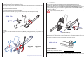
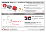
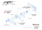
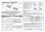
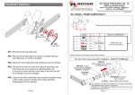
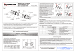
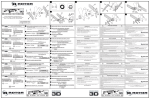
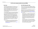
Read and understand
these instructions in
their entirety before
starting the installation
process.
SAFETY WARNING
This owner's manual contains important and useful information regarding the proper installation, operation,
care, and maintenance of your ROTORTM Ágilis crankset. Carefully read, follow and understand the
instructions given in this manual. You should keep this manual in a safe place for future reference.
Do not perform any modifications or adjustments that are not outlined in this manual. If you have any doubt
whatsoever regarding your ability to service or repair this product, please take your bicycle to a qualified
repair shop for the assistance of a professional mechanic.
Incorrect installation or service may impair performance, and could result in a dangerous situation leading
to injury or death.
Please have this product regularly inspected by a qualified mechanic for any signs of wear. Components
that have experienced excessive wear, cracks, deformations or impacts need immediate replacement.
Failure to perform maintenance could drastically reduce the service life of your Ágilis crankset and reduce
its performance.
If you have any questions, please contact a professional bike mechanic or your nearest ROTORTM dealer
for additional information.
Caution!: If any instructions within this User Manual are contrary to the instructions given by the
manufacturer of your BB set or pedals, contact their service department to explain your plan and request
their approval.
USER MANUAL
7
(REVISED: OCT-08)
Drive Side crank
arm (right)
Non-Drive Side
crank arm (left)
1
2 Semi-Integrated Spindle
(Adjustable lenght)
8 O-ring
6
Pedal
Washer
MAINTENANCE
Inspect your Ágilis cranks for cracks and serious scratches, looseness, damage or weakness before each
ride, and after every fall or crash. If any of the preceding conditions are present, do not use your Ágilis
cranks until they have been repaired or replaced.
WARNING: Continuing to use damaged parts may lead to loss of control of the bicycle and cause injury or
death.
It is the product users' responsibility to examine the product on a regular basis to determine the need for
service or replacement. Cyclist should inspect their bicycle and parts on a regular basis in order to detect
damage that may have occurred from normal use and abuse. Check all parts for damage and wear before
every use. Check the chainrings bolts and other fasteners periodically for tightness; do not over-tighten any
of them.
ROTOR WARRANTY POLICY:
- The Ágilis crankset and its components are guaranteed for 2 YEARS against any manufacturer defects or defective materials. In the
event of a warranty defect, Rotor´s sole obligation under this warranty is to repair or replace, at its option, the defective part or product at no
charge. Moreover, in some countries, Rotor is obliged to ensure any legal warranty defined by law for the customer's protection.
5 Aesthetic Bolt
(DO NOT TIGHTEN IT)
WARNING,
DO NOT DISASSEMBLE!
Parts #1, #2, #3 y #4 are a “semiintegrated” assembly.
Do not touch the fixed red nut (#4), and do not
disassemble the adjustment bolt (#3) of the non-drive
side crank arm (#1).
These parts are specially assembled at factory;
disassembling them may damage the parts.
Red Fixed Nut
4
DO NOT TOUCH
Steel Adjustment 3
bolt
DO NOT DISASSEMBLE,
only adjust.
- Elements subject to wear and breakdowns that the manufacturer is not responsible for, are not covered by this warranty.
- Failures or breakdowns caused by improper use, poor assembly or inadequate maintenance as declared in the instructions or the user
manual are not covered by this warranty.
Extractor Cap
- Always keep your receipt or invoice, this warranty does not cover products whose serial number or identification has been erased,
damaged or modified.
Sliding Washer 10
- The following acts void this warranty:
Drive-Side Crank Bolt 11
9
- Failure to fulfil the requirements above.
- Improper installation.
- Improper use or installation of inadequate parts.
Warranty Service: Original purchaser must send their Rotor product along with the retailer's original bill, credit card receipt or other
satisfactory proof of date of purchase of the product.
These instructions and instructions for other Rotor Bike Components products are available for download at:
www.rotorbike.com
Rotor Componentes Tecnológicos SL - [email protected]
Pol. Ind. Conmar C/Tajo Nave 6 AJALVIR MADRID SPAIN Tel. +34 918843846 Fax. +34 918843865
Aesthetic Bolt 5
(DO NOT TIGHTEN IT)
1.- Install your chainrings on the drive-side crank (#7).
If installing Q-Rings, be sure to regulate them correctly!
Use a small amount of low or medium strength thread-locker on the chainring bolts to prevent them from
loosening or creaking.
ADJUSTMENT:
Ensure that steps 1-6 have been completed successfully before proceeding to the next step.
3.- Insert the Spindle through the left side of the BB set.
Tip: Strap the crank to the chain-stay using a zip-tie or Velcro strap to ease later steps of assembly.
7.- If there is too little pressure on the BB bearings (evident if there is lateral play) tighten the
Adjustment-Bolt #3 on the left crank (tighten it clockwise with a 10mm Allen key). If there is too much
pressure (evident if there is too much rotational resistance), loosen bolt #3 (loosen it counterclockwise) and tighten again very slowly, ensuring that the cranks rotate freely without excessive play or
resistance in the BB set.
IMPORTANT: Be sure that the10mm Allen key reach the bottom of the adjustment bolt #3, and
keep it during the assembly step 7.
4.- Apply a small amount of grease to the o-ring (#8) and place it over the spindle.
DO NOT TIGHTEN the aesthetic bolts #5 of both crank arms.
2.- Install your BB set (Rotor-SABB, Rotor-BB1 or any other Shimano compatible BB set), following the
instructions for said bottom bracket set.
STEPS 1 TO 4
8 O-ring
TIGHTEN
STEP 7
LOOSEN
5.- Place the Drive-Side Crank on the spindle and using an 8mm Allen tool to fasten the Bolt (#11) to 26 ft·lbs
or 35 N·m.
5
6.- Using a 10mm Allen tool fasten the Extractor Cap (#9) softly, screwing approximately 90º (11 ft·lbs or 15
N·m).
Allen 10 mm
Aesthetic Bolt
(DO NOT TIGHTEN)
8.- Before installing the pedals, place a washer (#6) into the inset position located at each pedal hole.
9.- Place grease or medium strength removable thread-locker on the pedal threads in order to prevent
corrosion and noise.
10.- Tighten the pedal up to a torque of approximately 25.8 ft·lbs or 35 N·m.
STEPS 8 TO 10
STEP 5
Allen 8 mm
STEP 6
Allen 10 mm
35 N·m
15 N·m
DISASSEMBLY:
Slightly loosen the Extractor Cap (#9) on the DRIVE-SIDE CRANK ARM: unscrew it 90º counterclockwise using a 10mm Allen wrench.
DO NOT DISASSEMBLE THE EXTRACTOR CUP FROM THE DRIVE-SIDE CRANK ARM.
Then, unscrew the Drive-Side Crank Bolt (#11) counter-clockwise using a 8mm Allen wrench until the
crank arm is free of the tapered hectagon spindle.
* Chainrings are not shown in order to clarify the drawings.