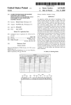
Transcript
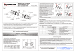
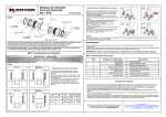
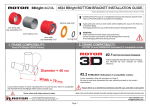
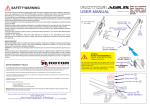
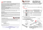
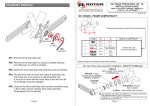
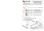
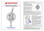
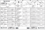
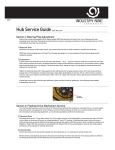
USER MANUAL
ROAD Self Aligning Bottom Bracket
Revised 12/06
S.A.B.B.
5 O-Ring (2x)
Fig #1
7 Right cup
1 Bearing cover
3 Spherical support
2 Bearing
Optional: ceramic bearing
2 Bearing
Optional: ceramic bearing
Flange
3 Spherical support
4 Left cup
1 Bearing cover
6 Internal sleeve
(Notice flange on the left end
of the internal sleeve)
We strongly recommend that you have a professional bike shop or expert bike mechanic install and service your ROTOR components.
Improper assembly and/or adjustment will significantly compromise the strength and life span of this component. If you choose to
install the component yourself, please follow the installation instructions carefully.
Compatibility: S.A.B.B. bottom brackets are compatible with BSA (68mm) or Italian (70mm) BB shells. They are also compatible with double
or triple chainring cranksets.
S.A.B.B. Installation Instructions
IMPORTANT – CAUTION !
If any instructions within this Technical Sheet are contrary to the instructions given by the manufacturer of your frame, including but
not limited to not using thread adhesive in the BB threads or not tightening the BB cups up to a torque value of 35-45 N-m or
26-35 ft-lbs, defer to the instructions from the frame manufacturer or phone their service department and explain your plan and
request their approval.
1- FRAME PREPARATION (VERY IMPORTANT)
A) Ensure that the BB shell ends are faced and square and clean
from paint.
B) It may be necessary for the BB shell to be “faced and chased” by
a professional bike mechanic.
C) Ensure that the BB shell threads are clean from all foreign particles
(machining chips, dirt, dust, etc).
D) Grease the BB shell threads before installing BB cups.
E) Ensure that your S.A.B.B. threads & width match your frame´s BB
shell width (see Fig #2 & below chart):
BB Shell
Nominal Width
BSA: 68 mm
ITA: 70 mm
Min/Max
Width Dimension
67/69 mm
69/71 mm
BB Shell
Thread
Right Cup
Thread
Clockwise
to tighten
Italian
36mm x 24tpi
Clockwise
to tighten
Clockwise
to tighten
2- INSTALL BB CUPS INTO FRAME
A) Apply a thin coat of thread adhesive (medium strenght removable
blue color) to the threads of the BB cups.
B) Hand press the flanged end of the internal sleeve into the left BB
cup until it bottoms-out. If your frame has BSA (English) threads,
notice that the right-cup and left-cup have different threads and are
marked Left-BSA or Right-BSA; the right cup has left-threads. If your
frame has Italian threads, both cups are the same and have rightthreads.
C) Thread the left BB cup (with internal sleeve installed) into the nondrive side of the frame´s BB shell as shown in Fig #3. The threads are
right-threads so turn it clockwise.
D) Using an external BB cup installation tool, (Park BBT-9 or Shimano
TL-FC32 / TL-FC33), tighten the left cup to 35-45 N·m / 26-33 ft-lbs
as shown in Fig #4.
E) Thread the right BB cup into the drive side of the frame´s BB shell
as shown in Fig #5. If English (BSA) threads, the threads are leftthreads so turn it counter-clockwise. If Italian threads, the threads are
right-treads so turn it clockwise.
F) Using the external BB cup tool, tighten the cup to 35-45 N·m /
26-33 ft-lbs as shown in Fig #6
-To remove the bearings from the cups:
1 Remove the cranks from the frame.
2 Remove the bearing-cover (#1) by inserting a finger into the
main hole and pulling the bearing-cover out. (See Fig #7)
3 See Fig-8 to remove the bearing-and-spherical-supportassembly from the cup using a strong flat-head screwdriver.
Insert the flat-head between the inside of the bearing-steeljacket and the flange on the inside of the cup; then twist the
handle which will twist the flat-head to pry the bearing-andspherical-support-assembly out.
4 Remove the bearing from the spherical-support; notice that
the spherical-support has an 'inside' and an 'outside'; it is
slightly tapered. The narrower tapered side faces into the
cup. If the spherical-support has grooves or is pitted in areas,
it should be replaced.
5 The bearing-seals can be carefully removed from the
bearings using a thin strong knife blade (work from the
outside diameter of the seal); be careful not to tear or
damage the seals. The bearings can be washed with solvent,
dried and re-lubricated with a very lightweight grease or oil.
Fig #7
1 Bearing cover
Fig #8
-To install the bearings back into the cups:
6 Apply a small amount of light grease into the cavity of the cup.
7 Hand press the spherical-support into the cup. The narrower tapered side faces into the cup.
8 Hand press the bearing into the spherical-support.
9 Hand press the bearing-cover over the bearing. Be sure that the edge of the bearing-cover fits into the
inner side of the spheric support.
10 Re-install the crankset into the frame.
- Never spray (shoot) water against the bottom bracket.
Fig #2
S.A.B.B. Spare parts list
Item Number
1
2
Left Cup
Thread
Counter-clockwise
English
BC1.37” x 24tpi to tighten
Maintenance
Drive
Side (R)
Non-Drive
Side (L)
3
BB Shell Width
Fig #3
4
5
6
Fig #4
7
Tightening
torque:
35-45 N·m
26-33 ft-lbs
Non-Drive
Side (L)
Fig #5
Drive
Side (R)
Fig #6
Tightening
torque:
35-45 N·m
26-33 ft-lbs
Italian
BB Shell
BSA BB
Shell
Description
Rotor code number
7P_SABB_TAP
7P_SABB_BSTD
7P_SABB_BCER
7P_SABB_HEM
7P_LCUP_SABB_R_B
7P_LCUP_SABB_R_I
7P_SABB_RING
7P_SABB_TUB
7P_RCUP_SABB_R_B
7P_RCUP_SABB_R_I
Bearing cover
Bearing-Steel
Optional ceramic bearing
Spherical support
Left cup English (BSA) Thread
Left cup Italian (ITA)Thread
O-Ring
Internal Sleeve
Right cup English (BSA) Thread
Right cup Italian (ITA) Thread
ROTOR WARRANTY POLICY
- All Rotor products and its components are guaranteed for 2 YEARS against any manufacturer defects or defective materials. In the event of
a warranty defect, Rotor´s sole obligation under this warranty is to repair or replace, at its option, the defective part or product at no charge.
Moreover, in some countries, Rotor is obligued to ensure any legal warranty defined by law for the customer´s protection.
- Elements subject to wear and breakdowns that the manufacturer is not responsible for, are not covered by this warranty.
- Failures or breakdowns caused by improper use, poor assembly or inadequate maintenance as declared in the instructions or the user
manual are not covered by this warranty.
- Always keep your receipt or invoice, this warranty does not cover products whose serial number or identification has been erased, damaged
or modified.
- Failure to fulfill the requirements above, improper installation, improper use or installation of inadequate parts void this warranty.
These instructions and instructions for other Rotor Bike
Components products are available for download at:
www.rotorbike.com
www.rotorbike.com
Rotor Componentes Tecnológicos SL - [email protected]
Ctra. Torrejón-Ajalvir, Km3’300 AJALVIR MADRID SPAIN
Tel. +34 918843846 Fax. +34 918843865