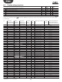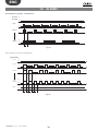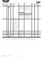
1
CPY controller Scheda per kit umidificatori KUE CAREL Control board for OEM humidifier kits KUE Manuale d’uso User manual NO POWER & SIGNAL CABLES TOGETHER READ CAREFULLY IN THE TEXT! High Efficiency Solutions ENG Content 1. INTRODUCTION & MODELS 5 2. ELECTRICAL CONNECTIONS 6 3. CPY & KUE: CONFIGURATION & RATED DATA 3.1 8 TAM (current transformer) configurations........................................................................................................................9 4. SIGNAL LEDS 10 5. USER TERMINAL (CODE CPYTERM*) 11 5.2 5.3 5.4 5.5 5.6 5.7 5.8 5.9 5.10 5.11 5.12 Keypad ....................................................................................................................................................................................11 Main display (parameter P0) .............................................................................................................................................12 Disabling.................................................................................................................................................................................12 Manually drain the water in the cylinder ........................................................................................................................12 Reset cylinder hour counter .............................................................................................................................................12 Accessing and setting the parameters .............................................................................................................................12 Recalling the manufacturer defaults ................................................................................................................................13 Parameters: Saving/recalling the user settings .............................................................................................................13 CPY configuration from CPYTERM200 terminal (and higher) ...................................................................................13 How to activate a configuration from CPYTREM200 (starting from release 8.3 only) .........................................14 How to activate a configuration from 1tool module Mod_CPY (starting from release 8.3 only) .....................14 6. CONFIGURATION PARAMETERS 6.1 6.2 6.3 6.4 15 Basic parameters ..................................................................................................................................................................15 Advanced parameters..........................................................................................................................................................15 Serial connection parameters (active when restarted) ................................................................................................15 Display-only parameters .....................................................................................................................................................16 7. CONTROLLING THE BOARD VIA NETWORK 7.1 7.2 7.3 7.4 7.5 20 Controlling production using variables I62 and I63 .....................................................................................................21 Read alarm log via the network ........................................................................................................................................21 Loss of network communication ......................................................................................................................................21 Modbus® RTU protocol on the CPY boards ................................................................................................................ 22 Exceptions managed .......................................................................................................................................................... 22 8. ADVANCED FUNCTIONS 8.1 8.2 8.3 8.4 8.5 8.6 8.7 8.8 8.9 22 Reset: cylinder hour counter “dA”, active alarms and alarm log .............................................................................. 22 Reset alarms and hour counter dA via terminal M2.7 ............................................................................................... 22 Reset via network ................................................................................................................................................................ 23 Reset from CPY terminal (parameter ‘dA’) .................................................................................................................. 23 Initial pre-wash of the lines and the cylinder............................................................................................................... 23 Reset e pre-lavaggio attraverso il terminale CPY - ..................................................................................................... 23 Description of alarms CY and Mn ................................................................................................................................... 23 Istruzioni per visualizzare release software ................................................................................................................... 23 Operating principle ............................................................................................................................................................. 24 3 +040000030 - rel. 2.7 - 07.10.2013 8.10 8.11 8.12 8.13 8.14 8.15 8.16 8.17 8.18 8.19 8.20 8.21 8.22 8.23 8.24 8.25 8.26 ON/OFF control ................................................................................................................................................................... 24 Proportional control............................................................................................................................................................ 24 Supply water conductivity.................................................................................................................................................. 24 Drain to dilute ...................................................................................................................................................................... 25 Manual calibration of the drain to dilute cycles ........................................................................................................... 25 Drain due to inactivity ........................................................................................................................................................ 26 Powered draining ................................................................................................................................................................ 26 Draining due to a significant reduction in the request for production ................................................................... 26 Periodical drain .................................................................................................................................................................... 26 Automatic insufficient supply water management ...................................................................................................... 27 Auxiliary contact management (active fan request) .................................................................................................... 27 Manual procedure............................................................................................................................................................... 27 Alarm relay switching ......................................................................................................................................................... 27 Management of high level and foam ............................................................................................................................. 27 Chattering of the drain valve during the fill cycles (not available with drain pump) .......................................... 28 Current limits for the electrodes: with & without current peaks in the first 20s after the contactor closes .. 28 Current limits for the electrodes: with & without current peaks in the first 20s after the contactor closes ... 29 9. TECHNICAL SPECIFICATIONS 29 10. ALARMS 30 MPORTANT WARNINGS: The CAREL product is a state-of-the-art device, whose operation is specified in the technical documentation supplied with the product or can be downloaded, even prior to purchase, from the website www.carel.com. The customer (manufacturer, developer or installer of the final equipment) accepts all liability and risk relating to the configuration of the product in order to reach the expected results in relation to the specific final installation and/or equipment. The failure to complete such phase, which is required/indicated in the user manual, may cause the final product to malfunction; CAREL accepts no liability in such cases. The customer must use the product only in the manner described in the documentation relating to the product. The liability of CAREL in relation to its products is specified in the CAREL general contract conditions, available on the website www.carel.com and/or by specific agreements with customers. DISPOSAL OF THE PRODUCT: The appliance (or the product) must be disposed of separately in accordance with the local waste disposal legislation in force The manual is available in other languages at www.carel.com ENG 1. INTRODUCTION & MODELS Electronic board for the control and management of CAREL KUE humidifier kits: • features all the inputs and outputs required to completely and independently control the humidifier; • features three LEDs to indicate active alarms present (red LED), steam production (yellow LED), 24 Vac power supply (green LED); • can be connected to the CPY terminal, or to the supervisor network with Modbus® or CAREL proprietary protocol (code CPYTERM***). CPY models for non-configured KUE humidifiers (to be configured using humiSet) CPY 00 0 * 0: protocoll CAREL A: Modbus 9600 Baud, B: Modbus 19200 Baud * 0o1 >=2 >=2 00 CPY models for KUE*R* humidifiers CPY ** R1: 1.5 kg/h reduced (3.3 lbs/hr) R3: 3 kg/h reduced (6.6 lbs/hr) * U: 208 Vac 1-ph.; D: 230 Vac 1-ph.; C: 200Vac 1-ph. *2 * P: drain pump V: drain valve 0 *2 * P: drain pump V: drain valve 0 *2 * P: drain pump V: drain valve 0 *2 * P: drain pump V: drain valve 0 *2 * P: drain pump V: drain valve 0 CPY models for KUE*1* humidifiers CPY ** 01: 1.5 kg/h (3.3 lbs/hr) 03: 3 kg/h (6.6 lbs/hr) * U: 208 Vac 1-ph. D: 230 Vac 1-ph.; C: 200Vac 1-ph.; U: 208 Vac 1-ph.; C: 200Vac 1-ph.; D: 230 Vac 1-ph.; J: 200 Vac 3-ph.; W: 208 Vac 3-ph. K: 230 Vac 3-ph.; L: 400 Vac 3-ph.; M: 460 Vac 3-ph. CPY models for KUE*2* humidifiers CPY ** 05: 5 kg/h (11 lbs/hr) 08: 8 kg/h (17 lbs/hr) * C: 200Vac 1-ph.; U: 208 Vac 1-ph.; D: 230 Vac 1-ph.; J: 200 Vac 3-ph.; W: 208 Vac 3-ph.; K: 230 Vac 3-ph.; L: 400 Vac 3-ph.; M: 460 Vac 3-ph.;N: 575 Vac 3-ph. J: 200 Vac 3-ph.; W: 208 Vac 3-ph.; K: 230 Vac 3-ph.; L: 400 Vac 3-ph.; M: 460 Vac 3-ph.; N: 575 Vac 3-ph. CPY models for KUE*3 humidifiers CPY ** 09: kg/h (20 lbs/hr) * U: 208 Vac 1-ph.; D: 230 Vac 1-ph. J: 200 Vac 3-ph. 10: 10 kg/h (22 lbs/hr) 15: 15 kg/h (33 lbs/hr) 18:18 kg/h (40 lbs/hr) W: 208 Vac 3-ph.; K: 230 Vac 3-ph.; L: 400 Vac 3-ph.; M: 460 Vac 3-ph.; N: 575 Vac 3-ph. L: 400 Vac 3-ph.; M: 460 Vac 3-ph.; N: 575 Vac 3-ph. CPY models for KUE*4 humidifiers (pump only) CPY ** 25: 25 kg/h (55 lbs/hr) 35: 35 kg/h (77 lbs/hr) 45: 45 kg/h (100 lbs/hr) * J: 200 Vac 3-ph. W: 208 Vac 3-ph.; K: 230 Vac 3-ph.; L: 400 Vac 3-ph.; M: 460 Vac 3-ph.; N: 575 Vac 3-ph. L: 400 Vac 3-ph.; M: 460 Vac 3-ph.; N: 575 Vac 3-ph. Options and accessories CAREL code CPYCONN000 CPYTERM000 con CPY****000 CPYTERM100 con CPY****100 CPYTERM200 con CPY****2*0 HUMISET0000 UMKDP00000 UEKTAM0001 Terminal kit (not supplied with CPY board) External CPY terminal with keypad humiSet (kit for programming CAREL humidifiers) CAREL strip remote LED plate External TAM 5 +040000030 - rel. 2.7 - 07.10.2013 ENG 2. ELECTRICAL CONNECTIONS Fig. 2.a J1 - tLAN connection and 30 Vdc power supply connection for CPY terminal 1 2 3 CAREL telephone cable code S90CONN000, already supplied with the CPY terminal (if other cables are used, do not exceed the length of 10 m (33 ft)(1)); two anti-EMI filters (code 0907858AXX) to be applied at the ends of the telephone cable, if the terminal is installed permanently; CPY terminal (CAREL code CPYTERM***). M8 - Power supply connection M8.1 In 24 Vac power supply (fit a 1A flast-blow fuse in the line - installer’s responsibility) M8.2 G0 24 Vac +10%/ -15%, 10 VA max, excluding solenoid valve M12 - tLAN network connection 9600 baud (default) / 19200 baud M12.1 In/Out tLAN data line M12.2 G0 Maximum cable length: 10 m (33 ft)(1), laid in separate conduits from power cables. M1 - RS485 network connection 9600 baud (default) / 19200 baud for CPY*000 e CPY*100 M1.1 + In/Out M1.2 M1.3 G0 for CPY*200 M1.1 In/Out M1.2 M1.3 Rx - / Tx Rx + / Tx + G0 Shielded cable, laid in separate conduits from power cables. Note: maximum shielded cable length: specified by the EIA RS485 protocol, equivalent to European standard CCITT V11, using shielded twisted pair cable, AWG26, 485 input stage impedance 1/8 unit-load (with this configuration, a maximum of 256 devices can be connected) laid in separate conduits from the power cables. M2 - Control signals (controller & ON/OFF) M2.1 Out M2.2 In M2.3 - +15 Vdc for power supply to active probe max 30 mA, protected against temporary short-circuit (max 1 minute) Control signal: ON/OFF contact between M2.2 and M2.3: open max 5 Vdc, closed max 7 mA 0 to 10 V & 2 to 10 V: impedance 20kΩ 0 to 20 & 4 to 20mA: impedance 100Ω G0 Ensure compliance with the electrical specifications shown in the table above, shielded cable; laid in separate conduits from power cables. +040000030 - rel. 2.7 - 07.10.2013 6 ENG M2 - Enable operation M2.4 In Input from external contact free; max 5 Vdc (open), max 5 mA (closed) M2.5 In Maximum cable length: 10 m (33 ft)(1), laid in separate conduit from power cables. M2 - Manual drain M2.6 In Input from external contact (to G0); max 5 Vdc (open), max 5 mA (closed) M2.5 In Maximum cable length: 10 m (33 ft)(1), laid in separate conduit from power cables. M2 - Reset ‘dA’ cylinder hour counter and alarms M2.7 In Input from contact; max 5 Vdc (open), max 5 mA (closed) M2.5 In Maximum cable length: 10 m (33 ft)(1), laid in separate conduit from power cables. M5 - Alarm M5.1 M5.2 Out Out NO contact (*) EN60730: 250 Vac 5 A res / 2 A ind (cos=0.4) UL: 1 FLA / 6 LRA, C300 P.D. (*) The CPY board can be programmed so that the coil is energised when there are no alarms (see parameter ‘b1’). M7 - Current transformer input for measuring immersed electrode current (TAM) M7.2 In TAM input M7.3 In Maximum cable length: 10 m, laid in separate conduits from power cables. M14 - AUX Relay M14.1 M14.2 M14.3 OUT NC C NO EN 60730: 250 Vac 8 A res / 2 A ind (cos=0.4) UL: 2A FLA / 12A LRA, C300 P.D. (N.O./N.C.) M11 - Fill and drain water solenoid valve control M11.1 Out fill solenoid valve: TRIAC connects 24Vac to ground G0; M11.2 24Vac, max: 0.75 A M11.3 Out drain control: TRIAC connects 24Vac to ground G0; Maximum cable length: 10 m (33 ft)(1) M6 - Drain pump activation M6.1 M6.2 Out NO contact EN60730: 250 Vac 5 A res / 2 A ind (cos=0.4) UL: 1 FLA / 6 LRA, C300 P.D. Maximum cable length: 10 m (33 ft)(1) (1) M10 - Contactor activation contact for immersed electrode voltage M10.1 M10.2 Out NO contact EN60730: 250 Vac 5 A res / 2 A ind (cos=0.4) UL: 1 FLA / 6 LRA, C300 P.D. Observe specifications of the loads, lay in separate conduits from power cables. M14 - Relè aux (ventilated steam distributor or indication of humidifier in production) M114.1 M114.2 M114.3 Out NC C NO EN 60730: 250 Vac 8 A res / 2 A ind (cos=0.4) UL: 2A FLA / 12A LRA, C300 P.D. (N.O./N.C.) 7 +040000030 - rel. 2.7 - 07.10.2013 ENG M3 - Conductivity meter M3.1 In Connection to CAREL conductivity meter M3.2 In Maximum cable length 10 m, laid in separate conduits from power cables. M9 - High water level sensor M9.1 In Connection to CAREL cylinder level sensor M9.2 In Maximum cable length 10 m, laid in separate conduits from power cables. JS6 - CAREL strip connection for remote LED plate JS6.1 JS6.2 JS6.3 JS6.4 Out Common +5 Vdc Red LED Yellow LED Green LED (1) For lengths greater than 10 m (33 ft) use shielded cable with the shield connected to PE both on the terminal side and the controller side. 3. KUE kg/h(1) (2) kW 1,5 KUESR* 3,0 KUETR* 3,0 1,5 KUE*1* 3,0 KUES2* KUES3* 5,0 8,7 9,0 5,0 KUET2* 8,0 CPY & KUE: CONFIGURATION & RATED DATA Vac 200 1,13 208 230 200 2,25 208 230 208 230 2,25 400 460 200 1,13 208 230 200 208 230 200 2,25 208 230 400 460 200 3,75 208 230 6,52 208 6,75 230 200 208 230 3,75 400 460 575 200 208 230 6,00 400 460 575 Ph 1 1 1 1 1 1 3 3 3 3 1 1 1 1 1 1 3 3 3 3 3 1 1 1 1 1 3 3 3 3 3 3 3 3 3 3 3 3 +040000030 - rel. 2.7 - 07.10.2013 Inom [A] 5.6 5.4 4.9 11.3 10.8 9.8 6.2 5.6 3.2 2.8 5.6 5.4 4.9 11.3 10.8 9.8 6.5 6.2 5.6 3.2 2.8 18.8 18.0 16.3 31.4 29.3 10.8 10.4 9.4 5.4 4.7 3.8 17.3 16.7 15.1 8.7 7.5 6.0 CPY board CPYR1C* CPYR1U* CPYR1D* CPYR3C* CPYR3U* CPYR3D* CPYR3W* CPYR3K* CPYR3L* CPYR3M* CPY01C* CPY01U* CPY01D* CPY03C* CPY03U* CPY03D* CPY03J* CPY03W* CPY03K* CPY03L* CPY03M* CPY05C* CPY05U* CPY05D* CPY09U* CPY09D* CPY05J* CPY05W* CPY05K* CPY05L* CPY05M* CPY05N* CPY08J* CPY08W* CPY08K* CPY08L* CPY08M* CPY08N* TAM TAM (fig. 3.1) for cylinder Turns settings with snap-on connection 100 1 a 100 1 a 100 2 d 300 2 d 300 2 d 100 1 a 100 1 a 100 1 a 100 2 d 100 2 d 100 1 a 100 1 a 100 2 d 300 2 d 300 2 d 100 1 a 100 1 a 100 1 a 100 1 a 100 2 d 100 2 d 500 2 d(*) 500 2 d(*) 500 2 d(*) 500 1 a 500 1 a 300 2 d(*) 100 1 c 100 1 c 100 1 a 100 2 d 100 2 d 500 2 d(*) 500 2 d(*) 300 2 d(*) 100 1 a 100 1 a 100 1 a 8 TAM (fig. 3.1) for cylinder with screw connection a a d d d a a a d d a a d d d a a a a d d d d d a a d a a a d d d d d a a a ENG KUE KUET3* kg/h(1) (2) kW 10,0 7,50 15,0 11,25 18,0 13,50 KUET3* 25 KUET4* 35 45 33,75 Vac Ph 200 208 230 400 460 575 200 208 230 400 460 575 400 460 575 200 208 230 400 460 575 200 208 230 400 460 575 400 460 575 3 3 3 3 3 3 3 3 3 3 3 3 3 3 3 3 3 3 3 3 3 3 3 3 3 3 3 3 3 3 Inom [A] 21.7 20.8 18.8 10.8 9.4 7.5 32.5 31.2 28.2 16.2 14.1 11.3 19.5 16.9 13.6 54.1 52.0 47.1 27.1 23.5 18.8 75.8 72.9 65.9 37.9 32.9 26.4 48.7 42.4 33.9 CPY board CPY10J* CPY10W* CPY10K* CPY10L* CPY10M* CPY10N* CPY15J* CPY15W* CPY15K* CPY15L* CPY15M* CPY15N* CPY18L* CPY18M* CPY18N* CPY25J* CPY25W* CPY25K* CPY25L* CPY25M* CPY25N* CPY35J* CPY35W* CPY35K* CPY35L* CPY35M* CPY35N* CPY45L* CPY45M* CPY45N* TAM TAM (fig. 3.1) for cylinder Turns settings with snap-on connection 300 1 c 300 1 c 300 1 c 300 1 a 100 1 a 100 1 a 500 1 c 500 1 c 300 1 c 300 1 a 300 1 a 300 1 a 300 1 a 300 1 a 300 2 d 500 1 b 500 1 b 500 1 b 500 1 c 500 1 c 500 1 c 700 1 c 700 1 c 700 1 c 500 1 c 500 1 c 500 1 c 700 1 c 700 1 c 700 1 c TAM (fig. 3.1) for cylinder with screw connection a a a a a a a a a a a a a a d b b b c c c c c c c c c c c c Tab. 3.a 3.1 TAM (current transformer) configurations 100 300 500 700 one cable turn one turn of the two two cable turns one cable in “double three cable turns cables of the same of the same turn” mode of the same phase phase phase 100 300 500 700 (2) 100 300 500 700 (1) The TAM must be positioned upstream of the contactor when using cylinders with snap-on connection. The average steam production is affected by external factors, such as: ambient temperature, quality of the supply water and steam distribution system. Tolerance on the rated values: from -10% to +5 % (EN 60335-1). 100 300 500 700 : 100 300 500 700 (*) CPY* Fig. 3.b Fig. 3.c Fig. 3.d 9 Fig. 3.e Fig. 3.f +040000030 - rel. 2.7 - 07.10.2013 ENG 4. SIGNAL LEDS Legenda 3 2 1 3 M14 LED on board 2 COM R Y G M7 Terminal Symbols Meaning (R) Red alarm active (the alarm can be identified by the type of flashing, see the table of alarms) (Y) Yellow steam production in progress(LED always on 100% production, 2 flashes 20%, 3 flashes 30%, …) (G) Green 24 Vac power connected JS 6 Note: The yellow and red LEDs are active only if the display is disconnected. Fig. 4.a Diagrams describing the flashes 1. Steam production: yellow LED - Temporary production (“short flashes”) PRODUZIONE ON < 1% OFF 1 ON 1 1-19% 1 3s 1 3s 1 1 3s 3s time 1 3s 3s OFF time 1 2 ON 1 2 20-29% 3s 1 2 1 2 3s 1 2 3s 1 2 3s 3s OFF time 1 ON 5 9 90-99% 1 5 9 1 3s 5 9 3s OFF 1s time Fig. 4.b 2. Steam production: yellow LED - Steady production (“long flashes”) PRODUZIONE ON < 1% OFF time 20-29% ON 1 2 1 2 1 3s 2 3s 1 2 3s OFF time 90-99% ON 1 2 3 4 5 6 7 8 9 1 3s OFF time 100% ON OFF 1s 1s 1s 1s 1s time Fig. 4.c Fast flash: 0.2 seconds ON and 0.2 seconds OFF; Slow flash: 1 second ON and 1 second OFF Each set of impulses is separated from the next by a 3 second pause, to allow the user to count the impulses in each set: this allows the instant steam production to be identified. +040000030 - rel. 2.7 - 07.10.2013 10 ENG 5. USER TERMINAL CODE CPYTERM* The CPY board - via terminal J1 - can be connected to the CPY terminal (CAREL code CPYTERM000) for displaying the status and alarms relating to the board and setting the operating parameters (useful for service or maintenance). drain esc humiSteam easy Fig. 5.a Attention: the softwares of CPY* and CPYTERM* must match each other, i.e. the 8th digits of the respective codes must be equal. In case there is no match, some parameters di CPY* might not be accessible. If there is no match, on power-up after displaying the software release, and in normal operation when pressing UP+PRG, the red LED of CPY* will remain on for 5 seconds, and the following error message will be displayed: “X – Y”, where “X” and “Y” are the 2 different 8th digits. Refer to the after-sales service. Symbols on the terminal manual cylinder drain steam flow-rate (international system, default) power supply (green LED) parameter programming in progress (parameter setup) humidifier operating (yellow LED) Flashing: steam production not yet in steady operation Steady: steam production in steady operation alarm (red LED, not flashing) Alarm activated: LED flashing and buzzer active If an alarm is active pressing ESC mutes the buzzer and the LED comes on steady, pressing ESC again resets the alarms (see Chap. 8) conductivity value maintenance request (alarm in progress) or display alarm log (HYS) 3 digits, after 999 it displays to indicate 1000 (displays three digits with a point at the top between the first and the second digit). steam production in progress time in seconds instant current in amperes cylinder filling in progress foam in the cylinder hours water present steam production as a percentage of rated capacity cylinder water drain in progress on steady: external fan or steam production active. Flashing: external fan or steam production awaiting start/stop Tab. 5.a 5.2 Keypad button function return to the previous display from the main screen: pressed for 5 seconds disables/enables the humidifier UP DOWN ENTER (and PRG) from the main screen: display the humidification values (current, conductivity,....), from the list of parameters: circular navigation of the parameters and set the values from the main screen: display the humidification values (current, conductivity,....), from the list of parameters: circular navigation of the parameters and set the values for 2 seconds: access the list of parameters from the list of parameters: select and confirm (like the “Enter” key on a computer keyboard) Tab. 5.b 11 +040000030 - rel. 2.7 - 07.10.2013 ENG 5.3 Main display (parameter P0) The display normally shows the current steam production (kg/h, basic display). To display other values, press UP or DOWN and scroll the following list: • current (A) • supply water conductivity (μS/cm) • cylinder hour counter (h) • input signal (0-100%, or ON/OFF if A0=0) • maximum steam production control (parameter P0) (*) • access alarm log (HIS ) (**) To return to the basic display, press ESC. Parameter C0 can be used to change the value of the basic display (default: current steam production). (*) To modify the maximum steam output (P0) press: • ENTER (display: ) • UP or DOWN to set the production as a percentage (from 20 to100%) • ENTER to confirm the new value Press ESC to return to the main screen Parameter P0 can also be accessed from the list of parameters. (**) To display the alarm log (HIS ) press: • ENTER (the most recent alarm is shown) • UP or DOWN to scroll the list of alarms in chronological order Press ESC to return to the main screen. To delete the list of alarms press UP and DOWN for 5 seconds (inside the alarm log), when the list has been reset the display will show ‘res’. 5.4 Disabling The humidifier can be disabled in 3 different ways: • Opening contact M2.4 and M2.5 (enable) : the display shows C--; • From serial (see Chap. 7 Digital 2) : the display shows S--; • From terminal (see ESC button) : the display shows t--. 5.5 Manually drain the water in the cylinder Total drain in operation Press UP and DOWN together for 2 seconds (the message ‘dr’ on the display alternating with ‘tot’ indicates the function has been activated). Press UP and DOWN again for 2 seconds to stop the drain cycle. The drain cycle in any case ends automatically. 5.6 Reset cylinder hour counter • access parameter ‘dA’ • press UP & DOWN for 5 seconds When the counter has been reset, the display shows ‘res’. 5.7 Accessing and setting the parameters The configuration parameters are used to select and control the functions and the status of the humidifier. From the main screen press: • ENTER for 2 seconds, enter the password 77 using the UP or DOWN button, • ENTER to confirm and access the list of parameters, • UP or DOWN to scroll the list cyclically, • ENTER to select a parameter (display: ‘set’), • UP to modify (increase) the value of the parameter. To scroll the values faster press UP together with DOWN, • DOWN: as for UP to decrease the value • ENTER to save the new value and return to the list of parameters, or ESC to return to the list without saving the new value, Press ESC to return to the main screen. +040000030 - rel. 2.7 - 07.10.2013 12 ENG 5.8 Recalling the manufacturer defaults From the main screen press ENTER until the password screen is shown: • Enter the password 50 • The message dEF is displayed, flashing Confirm by pressing ENTER or exit by pressing ESC If no button is pressed for 30 seconds, the display returns to the main screen. 5.9 Parameters: Saving/recalling the user settings From the main screen, a copy of the user settings can be saved at any time, and then later recalled. To save the settings: From the main screen press: • ENTER for 2 seconds, • enter the password 51 using the UP or DOWN button and press ENTER, the message UbP (Backup User parameters) flashes, • press ENTER: the message -L- is displayed, flashing, • press UP or DOWN, the message–S- (Save) is displayed, flashing, • press ENTER to save a copy of the user settings, or press ESC to cancel the operation. NOTE: the copy of the user parameters saved previously will be overwritten with current user settings. To recall the settings: From the main screen press: • ENTER for 2 seconds, • enter the password 51 using the UP or DOWN button and press ENTER, the message UbP (Backup User parameters) flashes, • press ENTER: the message -L- (Loading) is displayed flashing, • press ENTER to recall the previously saved copy of the user settings, or press ESC to cancel the operation. If no button is pressed for 30 seconds, the display returns to the main screen, without performing the operation. 5.10 CPY configuration from CPYTERM200 terminal (and higher) The CPY boards with software release 8.1 or higher have all the configurations (kg/h, Vac) stored permanently in the memory; boards with release 8.0, on the other hand, receive the configuration from humiSet. The configurations can be activated at any time, as follows: • CPY rel. 8.0, 8.1 and 8.2: from humiSet only. humiSet transfers the configurations to CPY 8.0, and activates those resident in the memory on CPY 8.1 and 8.2 • CPY rel. 8.3 and higher: from humiSet, from CPYTERM200 or 1tool module Mod_CPY (the following tables are to be used together with the 1tool modulel) KUE KUESR KUES1 KUESR KUETR KUES1 KUET1 kg/h 1.5 1.5 1.5 1.5 1.5 1.5 3 3 3 3 3 3 3 3 3 3 3 3 3 3 3 Vac 200 208 230 200 208 230 200 208 230 208 230 400 460 200 208 230 200 208 230 400 460 PH 1 1 1 1 1 1 1 1 1 3 3 3 3 1 1 1 3 3 3 3 3 Drain device pump pump pump pump pump pump pump pump pump pump pump pump pump pump pump pump pump pump pump pump pump CFG NO. 1 2 3 4 5 6 7 8 9 10 11 12 120 13 14 15 16 17 18 19 20 KUE KUES2 KUET2 KUET2 KUES3 13 kg/h 5 5 5 5 5 5 5 5 5 8 8 8 8 8 8 09 09 Vac 200 208 230 200 208 230 400 460 575 200 208 230 400 460 575 208 230 PH 1 1 1 3 3 3 3 3 3 3 3 3 3 3 3 1 1 Drain device pump pump pump pump pump pump pump pump pump pump pump pump pump pump pump pump pump CFG NO. 21 22 23 24 25 26 27 28 29 30 31 32 33 34 35 36 37 +040000030 - rel. 2.7 - 07.10.2013 ENG KUE KUET3 KUET4 kg/h 10 10 10 10 10 10 15 15 15 15 15 15 18 18 18 25 25 25 25 25 25 35 35 35 35 35 35 45 45 45 Vac 200 208 230 400 460 575 200 208 230 400 460 575 400 460 575 200 208 230 400 460 575 200 208 230 400 460 575 400 460 575 PH 3 3 3 3 3 3 3 3 3 3 3 3 3 3 3 3 3 3 3 3 3 3 3 3 3 3 3 3 3 3 Drain device pump pump pump pump pump pump pump pump pump pump pump pump pump pump pump pump pump pump pump pump pump pump pump pump pump pump pump pump pump pump CFG NO. 38 39 40 41 42 43 44 45 46 47 48 49 50 51 52 53 54 55 56 57 58 59 60 61 62 63 64 65 66 67 kg/h 1.5 1.5 1.5 1.5 1.5 1.5 3 3 3 3 3 3 3 3 3 3 3 3 3 3 3 5 5 5 5 5 5 5 5 5 8 8 8 8 8 8 09 09 Vac 200 208 230 200 208 230 200 208 230 208 230 400 460 200 208 230 200 208 230 400 460 200 208 230 200 208 230 400 460 575 200 208 230 400 460 575 208 230 PH 1 1 1 1 1 1 1 1 1 3 3 3 3 1 1 1 3 3 3 3 3 1 1 1 3 3 3 3 3 3 3 3 3 3 3 3 1 1 Drain device valve valve valve valve valve valve valve valve valve valve valve valve valve valve valve valve valve valve valve valve valve valve valve valve valve valve valve valve valve valve valve valve valve valve valve valve valve valve CFG NO. 68 69 70 71 72 73 74 75 76 77 78 79 121 80 81 82 83 84 85 86 87 88 89 90 91 92 93 94 95 96 97 98 99 100 101 102 103 104 Tab. 5.c KUE KUESR KUES1 KUESR KUETR KUES1 KUET1 KUES2 KUET2 KUET2 KUES3 +040000030 - rel. 2.7 - 07.10.2013 KUE KUET3 kg/h 10 10 10 10 10 10 15 15 15 15 15 15 18 18 18 Vac 200 208 230 400 460 575 200 208 230 400 460 575 400 460 575 PH 3 3 3 3 3 3 3 3 3 3 3 3 3 3 3 Drain device valve valve valve valve valve valve valve valve valve valve valve valve valve valve valve CFG NO. 105 106 107 108 109 110 111 112 113 114 115 116 117 118 119 Tab. 5.d 5.11 How to activate a configuration from CPYTERM200 (starting from release 8.3 only) Proceed as follows: 1. Ritornare alla schermata principale 2. Press SEL + + together for at least 2 seconds until the display shows 00 3. Enter 64 using the arrows and press SEL to confirm 4. CFG is displayed 5. Press SEL 6. r1 is displayed: this is the first configuration, and refers to “r”educed cylinder 1.5 kg/h (“1”) 7. Scroll the configurations until reaching the desired option, using the arrows 8. Press SEL to select the option in kg/h 9. 1PH is displayed if the kg/h selected supports both single-phase and three-phase power, otherwise 3PH is displayed for kg/h values that only accept three-phase power (VAC) 10. Select the VAC with the arrows and press SEL to confirm 11. P is displayed, referring to the drain pump 12. Select P or U (for drain valve) with the arrows, then confirm by pressing SEL 13. Press SEL to activate the chosen configuration 14. “Loading” is displayed during activation (around 10 s), after which CPY will begin normal operation 5.12 How to activate a configuration from 1tool module Mod_CPY (starting from release 8.3 only) Send the configuration number read in the CFG NO. column of the table to CPY using the 1tool module Mod_CPY (see the corresponding manual for further information; the manual is included in 1tool together with the module). 14 ENG 6. 6.1 CONFIGURATION PARAMETERS Basic parameters P0 A0 A1 A2 maximum production (see prev. page “main display”) operating mode: 0= ON/OFF control; 1= proportional unit of measure: 0= kg/h; 1= lb/h type of production request signal (the parameter can be displayed when A0=1): 1=0 to 10 V; 2= 2 to 10 V; 3= 0 to 20 mA; 4= 4 to 20 mA A6 Relay M14 activation delay for signalling presence of steam production request / activating external fan A7 Relay M14 deactivation delay for signalling presence of steam production request / deactivating external fan C0 value normally displayed 1= input/control signal displayed; 2= steam production; 3= hour counter; 4 = conductivity; 5= current UoM % - Range 20...100 0...1 0...1 1...4 DEF Note 100 1 0 1 s 0…300 0 s 0…300 180 - 1...5 2 Visible only if function activated (parameter b1, see par 11.6) Visible only if function activated (parameter b1, see par 11.6) Tab. 6.a 6.2 b1 b2 b4 b5 b6 b7 b8 b9 bb bE bF Advanced parameters optional functions (see following paragraph) off delay time Override conductivity of the water 0= automatic measurement; >0 = conductivity forced by b4 conductivity pre-alarm threshold (*) conductivity alarm threshold (*) foam control threshold 0= no foam detection; 1= max. foam detection sensitivity; 100= min. foam detection sensitivity conductivity control inside the cylinder in steady operation compared to rated value (less than 100%: the conductivity increases) adjust duration of the drain to dilute cycle cylinder maintenance limit time (in hours): 0= the cylinder life alarm “CY” and maintenance required alarm “Mn” are not shown. (*) time limit between two periodical drain cycles (available only if the periodical drain is enabled, 64 set for b1) days delay for drain due to inactivity (not available if the drain due to inactivity has been disabled, 8 set for b1) UoM s μS/cm Range 0…255 0…120 0…1250 DEF 0 0 0 μS/cm 0…2000 μS/cm 0....2000 % 0…100 1500 2000 50 % 50…200 100 % h 50…200 0...4000 100 3000 h 1…240 24 days 1…199 3 Note Tab. 6.b (*) after 999 the display shows to indicate 1000 (three digits plus a point at the top between the first and second digit are displayed). 6.3 C3 C4 C5 C6 C7 C8 Serial connection parameters (active when restarted) serial address baud rate: 0= 9,600; 1= 19,200 supervisor: frame (character bits, parity, stop bits) 0=8,N,2 1=8,N,1 2=8,E,2 3=8,E,1 4=8,O,2 5=8,O,1 6=7,N,2 7=7,N,1 8=7,E,2 9=7,E,1 10=7,O,2 11=7,O,1 serial response transmission delay protocol: 0= CAREL supervisor; 1=Modbus® maximum time with no data (sent to controller) over RS485 to generate stop production and “SU” alarm UoM - Range 1…207 0...1 0 … 11 ms 0...199 0...1 0.1s 0...300 (es: 50=5s) DEF 1 0 0 0 0 5.0 Note see table “I” 62 Tab. 6.c 15 +040000030 - rel. 2.7 - 07.10.2013 ENG 6.4 d1 d3 d5 d6 d7 d9 dA db Display-only parameters display external request signal (only if A0=1) display instant steam flow-rate (instant value) supply water conductivity (*) current display maximum production (corresponding to value set for P0) rated steam production cylinder hour counter (can be reset) unit hour counter (cannot be reset, read only) UM % kg/h μS/cm A kg/h kg/h h h Range 0.0...100 0.0...199 0...1500 0.0...199 0.0...199 0.0...199 DEF Note - Tab. 6.d (*) after 999 the display shows to indicate 1000 (three digits plus a point at the top between the first and second digit are displayed). b1 Dilution Alarm relay oscillation when drain with “CY” alarm is on contactor 0 (def ) 1 2 3 4 5 6 7 8 9 10 11 12 13 14 15 16 17 18 19 20 21 22 23 24 25 26 27 28 29 30 31 32 33 34 35 36 37 38 39 40 41 42 43 44 45 46 47 48 49 50 51 52 53 54 55 OFF ON OFF ON OFF ON OFF ON OFF ON OFF ON OFF ON OFF ON OFF ON OFF ON OFF ON OFF ON OFF ON OFF ON OFF ON OFF ON OFF ON OFF ON OFF ON OFF ON OFF ON OFF ON OFF ON OFF ON OFF ON OFF ON OFF ON OFF ON open open closed closed open open closed closed open open closed closed open open closed closed open open closed closed open open closed closed open open closed closed open open closed closed open open closed closed open open closed closed open open closed closed open open closed closed open open closed closed open open closed closed +040000030 - rel. 2.7 - 07.10.2013 Drain if new request ≤ 2/3 current request (contact open) ) YES YES YES YES NO NO NO NO YES YES YES YES NO NO NO NO YES YES YES YES NO NO NO NO YES YES YES YES NO NO NO NO YES YES YES YES NO NO NO NO YES YES YES YES NO NO NO NO YES YES YES YES NO NO NO NO Total drain Display of “CL” due to inactivity & “CP” alarms ON (bF) ON ON (bF) ON ON (bF) ON ON (bF) ON ON (bF) ON ON (bF) ON ON (bF) ON ON (bF) ON OFF ON OFF ON OFF ON OFF ON OFF ON OFF ON OFF ON OFF ON ON (bF) OFF ON (bF) OFF ON (bF) OFF ON (bF) OFF ON (bF) OFF ON (bF) OFF ON (bF) OFF ON (bF) OFF OFF OFF OFF OFF OFF OFF OFF OFF OFF OFF OFF OFF OFF OFF OFF OFF ON (bF) ON ON (bF) ON ON (bF) ON ON (bF) ON ON (bF) ON ON (bF) ON ON (bF) ON ON (bF) ON OFF ON OFF ON OFF ON OFF ON OFF ON OFF ON OFF ON OFF ON ON (bF) OFF ON (bF) OFF ON (bF) OFF ON (bF) OFF ON (bF) OFF ON (bF) OFF ON (bF) OFF ON (bF) OFF 16 Alarm relay activated Periodical Enable management of if... total drai steam request signal / external fan control relay M14 alarms in progress OFF Disabled alarms in progress OFF Disabled alarms in progress OFF Disabled alarms in progress OFF Disabled alarms in progress OFF Disabled alarms in progress OFF Disabled alarms in progress OFF Disabled alarms in progress OFF Disabled alarms in progress OFF Disabled alarms in progress OFF Disabled alarms in progress OFF Disabled alarms in progress OFF Disabled alarms in progress OFF Disabled alarms in progress OFF Disabled alarms in progress OFF Disabled alarms in progress OFF Disabled alarms in progress OFF Disabled alarms in progress OFF Disabled alarms in progress OFF Disabled alarms in progress OFF Disabled alarms in progress OFF Disabled alarms in progress OFF Disabled alarms in progress OFF Disabled alarms in progress OFF Disabled alarms in progress OFF Disabled alarms in progress OFF Disabled alarms in progress OFF Disabled alarms in progress OFF Disabled alarms in progress OFF Disabled alarms in progress OFF Disabled alarms in progress OFF Disabled alarms in progress OFF Disabled no alarms in progress OFF Disabled no alarms in progress OFF Disabled no alarms in progress OFF Disabled no alarms in progress OFF Disabled no alarms in progress OFF Disabled no alarms in progress OFF Disabled no alarms in progress OFF Disabled no alarms in progress OFF Disabled no alarms in progress OFF Disabled no alarms in progress OFF Disabled no alarms in progress OFF Disabled no alarms in progress OFF Disabled no alarms in progress OFF Disabled no alarms in progress OFF Disabled no alarms in progress OFF Disabled no alarms in progress OFF Disabled no alarms in progress OFF Disabled no alarms in progress OFF Disabled no alarms in progress OFF Disabled no alarms in progress OFF Disabled no alarms in progress OFF Disabled no alarms in progress OFF Disabled no alarms in progress OFF Disabled no alarms in progress OFF Disabled ENG b1 Alarm relay Dilution oscillation when drain with “CY” alarm is on contactor 56 57 58 59 60 61 62 63 64 65 66 67 68 69 70 71 72 73 74 75 76 77 78 79 80 81 82 83 84 85 86 87 88 89 90 91 92 93 94 95 96 97 98 99 100 101 102 103 104 105 106 107 108 109 110 111 112 113 114 115 116 117 118 119 120 121 122 123 124 125 126 127 OFF ON OFF ON OFF ON OFF ON OFF ON OFF ON OFF ON OFF ON OFF ON OFF ON OFF ON OFF ON OFF ON OFF ON OFF ON OFF ON OFF ON OFF ON OFF ON OFF ON OFF ON OFF ON OFF ON OFF ON OFF ON OFF ON OFF ON OFF ON OFF ON OFF ON OFF ON OFF ON OFF ON OFF ON OFF ON OFF ON open open closed closed open open closed closed open open closed closed open open closed closed open open closed closed open open closed closed open open closed closed open open closed closed open open closed closed open open closed closed open open closed closed open open closed closed open open closed closed open open closed closed open open closed closed open open closed closed open open closed closed open open closed closed Drain if new request ≤ 2/3 current request (contact open) ) YES YES YES YES NO NO NO NO YES YES YES YES NO NO NO NO YES YES YES YES NO NO NO NO YES YES YES YES NO NO NO NO YES YES YES YES NO NO NO NO YES YES YES YES NO NO NO NO YES YES YES YES NO NO NO NO YES YES YES YES NO NO NO NO YES YES YES YES NO NO NO NO Total drain Display due to of “CL” inactivity & “CP” alarms OFF OFF OFF OFF OFF OFF OFF OFF OFF OFF OFF OFF OFF OFF OFF OFF ON (bF) ON ON (bF) ON ON (bF) ON ON (bF) ON ON (bF) ON ON (bF) ON ON (bF) ON ON (bF) ON OFF ON OFF ON OFF ON OFF ON OFF ON OFF ON OFF ON OFF ON ON (bF) OFF ON (bF) OFF ON (bF) OFF ON (bF) OFF ON (bF) OFF ON (bF) OFF ON (bF) OFF ON (bF) OFF OFF OFF OFF OFF OFF OFF OFF OFF OFF OFF OFF OFF OFF OFF OFF OFF ON (bF) ON ON (bF) ON ON (bF) ON ON (bF) ON ON (bF) ON ON (bF) ON ON (bF) ON ON (bF) ON OFF ON OFF ON OFF ON OFF ON OFF ON OFF ON OFF ON OFF ON ON (bF) OFF ON (bF) OFF ON (bF) OFF ON (bF) OFF ON (bF) OFF ON (bF) OFF ON (bF) OFF ON (bF) OFF OFF OFF OFF OFF OFF OFF OFF OFF OFF OFF OFF OFF OFF OFF OFF OFF 17 Alarm relay activated Periodical Enable management of if... total drai steam request signal / external fan control relay M14 no alarms in progress OFF Disabled no alarms in progress OFF Disabled no alarms in progress OFF Disabled no alarms in progress OFF Disabled no alarms in progress OFF Disabled no alarms in progress OFF Disabled no alarms in progress OFF Disabled no alarms in progress OFF Disabled alarms in progress ON (bE) Disabled alarms in progress ON (bE) Disabled alarms in progress ON (bE) Disabled alarms in progress ON (bE) Disabled alarms in progress ON (bE) Disabled alarms in progress ON (bE) Disabled alarms in progress ON (bE) Disabled alarms in progress ON (bE) Disabled alarms in progress ON (bE) Disabled alarms in progress ON (bE) Disabled alarms in progress ON (bE) Disabled alarms in progress ON (bE) Disabled alarms in progress ON (bE) Disabled alarms in progress ON (bE) Disabled alarms in progress ON (bE) Disabled alarms in progress ON (bE) Disabled alarms in progress ON (bE) Disabled alarms in progress ON (bE) Disabled alarms in progress ON (bE) Disabled alarms in progress ON (bE) Disabled alarms in progress ON (bE) Disabled alarms in progress ON (bE) Disabled alarms in progress ON (bE) Disabled alarms in progress ON (bE) Disabled alarms in progress ON (bE) Disabled alarms in progress ON (bE) Disabled alarms in progress ON (bE) Disabled alarms in progress ON (bE) Disabled alarms in progress ON (bE) Disabled alarms in progress ON (bE) Disabled alarms in progress ON (bE) Disabled alarms in progress ON (bE) Disabled no alarms in progress ON (bE) Disabled no alarms in progress ON (bE) Disabled no alarms in progress ON (bE) Disabled no alarms in progress ON (bE) Disabled no alarms in progress ON (bE) Disabled no alarms in progress ON (bE) Disabled no alarms in progress ON (bE) Disabled no alarms in progress ON (bE) Disabled no alarms in progress ON (bE) Disabled no alarms in progress ON (bE) Disabled no alarms in progress ON (bE) Disabled no alarms in progress ON (bE) Disabled no alarms in progress ON (bE) Disabled no alarms in progress ON (bE) Disabled no alarms in progress ON (bE) Disabled no alarms in progress ON (bE) Disabled no alarms in progress ON (bE) Disabled no alarms in progress ON (bE) Disabled no alarms in progress ON (bE) Disabled no alarms in progress ON (bE) Disabled no alarms in progress ON (bE) Disabled no alarms in progress ON (bE) Disabled no alarms in progress ON (bE) Disabled no alarms in progress ON (bE) Disabled no alarms in progress ON (bE) Disabled no alarms in progress ON (bE) Disabled no alarms in progress ON (bE) Disabled no alarms in progress ON (bE) Disabled no alarms in progress ON (bE) Disabled no alarms in progress ON (bE) Disabled no alarms in progress ON (bE) Disabled no alarms in progress ON (bE) Disabled Tab. 6.e +040000030 - rel. 2.7 - 07.10.2013 ENG b1 128 129 130 131 132 133 134 135 136 137 138 139 140 141 142 143 144 145 146 147 148 149 150 151 152 153 154 155 156 157 158 159 160 161 162 163 164 165 166 167 168 169 170 171 172 173 174 175 176 177 178 179 180 181 182 183 184 185 186 187 188 189 190 191 192 193 194 195 196 197 198 199 200 Alarm relay Dilution Drain if new oscillation when drain with request ≤ 2/3 “CY” alarm is on contactor current request (contact open) ) OFF open YES ON open YES OFF closed YES ON closed YES OFF open NO ON open NO OFF closed NO ON closed NO OFF open YES ON open YES OFF closed YES ON closed YES OFF open NO ON open NO OFF closed NO ON closed NO OFF open YES ON open YES OFF closed YES ON closed YES OFF open NO ON open NO OFF closed NO ON closed NO OFF open YES ON open YES OFF closed YES ON closed YES OFF open NO ON open NO OFF closed NO ON closed NO OFF open YES ON open YES OFF closed YES ON closed YES OFF open NO ON open NO OFF closed NO ON closed NO OFF open YES ON open YES OFF closed YES ON closed YES OFF open NO ON open NO OFF closed NO ON closed NO OFF open YES ON open YES OFF closed YES ON closed YES OFF open NO ON open NO OFF closed NO ON closed NO OFF open YES ON open YES OFF closed YES ON closed YES OFF open NO ON open NO OFF closed NO ON closed NO OFF open YES ON open YES OFF closed YES ON closed YES OFF open NO ON open NO OFF closed NO ON closed NO OFF open YES +040000030 - rel. 2.7 - 07.10.2013 Total drain Display of Alarm relay activated Periodical Enable management of due to “CL” & “CP” if... total drai steam request signal / inactivity alarms external fan control relay M14 ON (bF) ON alarms in progress OFF Enabled ON (bF) ON alarms in progress OFF Enabled ON (bF) ON alarms in progress OFF Enabled ON (bF) ON alarms in progress OFF Enabled ON (bF) ON alarms in progress OFF Enabled ON (bF) ON alarms in progress OFF Enabled ON (bF) ON alarms in progress OFF Enabled ON (bF) ON alarms in progress OFF Enabled OFF ON alarms in progress OFF Enabled OFF ON alarms in progress OFF Enabled OFF ON alarms in progress OFF Enabled OFF ON alarms in progress OFF Enabled OFF ON alarms in progress OFF Enabled OFF ON alarms in progress OFF Enabled OFF ON alarms in progress OFF Enabled OFF ON alarms in progress OFF Enabled ON (bF) OFF alarms in progress OFF Enabled ON (bF) OFF alarms in progress OFF Enabled ON (bF) OFF alarms in progress OFF Enabled ON (bF) OFF alarms in progress OFF Enabled ON (bF) OFF alarms in progress OFF Enabled ON (bF) OFF alarms in progress OFF Enabled ON (bF) OFF alarms in progress OFF Enabled ON (bF) OFF alarms in progress OFF Enabled OFF OFF alarms in progress OFF Enabled OFF OFF alarms in progress OFF Enabled OFF OFF alarms in progress OFF Enabled OFF OFF alarms in progress OFF Enabled OFF OFF alarms in progress OFF Enabled OFF OFF alarms in progress OFF Enabled OFF OFF alarms in progress OFF Enabled OFF OFF alarms in progress OFF Enabled ON (bF) ON no alarms in progress OFF Enabled ON (bF) ON no alarms in progress OFF Enabled ON (bF) ON no alarms in progress OFF Enabled ON (bF) ON no alarms in progress OFF Enabled ON (bF) ON no alarms in progress OFF Enabled ON (bF) ON no alarms in progress OFF Enabled ON (bF) ON no alarms in progress OFF Enabled ON (bF) ON no alarms in progress OFF Enabled OFF ON no alarms in progress OFF Enabled OFF ON no alarms in progress OFF Enabled OFF ON no alarms in progress OFF Enabled OFF ON no alarms in progress OFF Enabled OFF ON no alarms in progress OFF Enabled OFF ON no alarms in progress OFF Enabled OFF ON no alarms in progress OFF Enabled OFF ON no alarms in progress OFF Enabled ON (bF) OFF no alarms in progress OFF Enabled ON (bF) OFF no alarms in progress OFF Enabled ON (bF) OFF no alarms in progress OFF Enabled ON (bF) OFF no alarms in progress OFF Enabled ON (bF) OFF no alarms in progress OFF Enabled ON (bF) OFF no alarms in progress OFF Enabled ON (bF) OFF no alarms in progress OFF Enabled ON (bF) OFF no alarms in progress OFF Enabled OFF OFF no alarms in progress OFF Enabled OFF OFF no alarms in progress OFF Enabled OFF OFF no alarms in progress OFF Enabled OFF OFF no alarms in progress OFF Enabled OFF OFF no alarms in progress OFF Enabled OFF OFF no alarms in progress OFF Enabled OFF OFF no alarms in progress OFF Enabled OFF OFF no alarms in progress OFF Enabled ON (bF) ON alarms in progress ON (bE) Enabled ON (bF) ON alarms in progress ON (bE) Enabled ON (bF) ON alarms in progress ON (bE) Enabled ON (bF) ON alarms in progress ON (bE) Enabled ON (bF) ON alarms in progress ON (bE) Enabled ON (bF) ON alarms in progress ON (bE) Enabled ON (bF) ON alarms in progress ON (bE) Enabled ON (bF) ON alarms in progress ON (bE) Enabled OFF ON alarms in progress ON (bE) Enabled 18 ENG b1 201 202 203 204 205 206 207 208 209 210 211 212 213 214 215 216 217 218 219 220 221 222 223 224 225 226 227 228 229 230 231 232 233 234 235 236 237 238 239 240 241 242 243 244 245 246 247 248 249 250 251 252 253 254 255 Alarm relay Dilution Drain if new oscillation when drain with request ≤ 2/3 “CY” alarm is on contactor current request (contact open) ) ON open YES OFF closed YES ON closed YES OFF open NO ON open NO OFF closed NO ON closed NO OFF open YES ON open YES OFF closed YES ON closed YES OFF open NO ON open NO OFF closed NO ON closed NO OFF open YES ON open YES OFF closed YES ON closed YES OFF open NO ON open NO OFF closed NO ON closed NO OFF open YES ON open YES OFF closed YES ON closed YES OFF open NO ON open NO OFF closed NO ON closed NO OFF open YES ON open YES OFF closed YES ON closed YES OFF open NO ON open NO OFF closed NO ON closed NO OFF open YES ON open YES OFF closed YES ON closed YES OFF open NO ON open NO OFF closed NO ON closed NO OFF open YES ON open YES OFF closed YES ON closed YES OFF open NO ON open NO OFF closed NO ON closed NO Total drain Display of Alarm relay activated Periodical Enable management of due to “CL” & “CP” if... total drai steam request signal / inactivity alarms external fan control relay M14 OFF ON alarms in progress ON (bE) Enabled OFF ON alarms in progress ON (bE) Enabled OFF ON alarms in progress ON (bE) Enabled OFF ON alarms in progress ON (bE) Enabled OFF ON alarms in progress ON (bE) Enabled OFF ON alarms in progress ON (bE) Enabled OFF ON alarms in progress ON (bE) Enabled ON (bF) OFF alarms in progress ON (bE) Enabled ON (bF) OFF alarms in progress ON (bE) Enabled ON (bF) OFF alarms in progress ON (bE) Enabled ON (bF) OFF alarms in progress ON (bE) Enabled ON (bF) OFF alarms in progress ON (bE) Enabled ON (bF) OFF alarms in progress ON (bE) Enabled ON (bF) OFF alarms in progress ON (bE) Enabled ON (bF) OFF alarms in progress ON (bE) Enabled OFF OFF alarms in progress ON (bE) Enabled OFF OFF alarms in progress ON (bE) Enabled OFF OFF alarms in progress ON (bE) Enabled OFF OFF alarms in progress ON (bE) Enabled OFF OFF alarms in progress ON (bE) Enabled OFF OFF alarms in progress ON (bE) Enabled OFF OFF alarms in progress ON (bE) Enabled OFF OFF alarms in progress ON (bE) Enabled ON (bF) ON no alarms in progress ON (bE) Enabled ON (bF) ON no alarms in progress ON (bE) Enabled ON (bF) ON no alarms in progress ON (bE) Enabled ON (bF) ON no alarms in progress ON (bE) Enabled ON (bF) ON no alarms in progress ON (bE) Enabled ON (bF) ON no alarms in progress ON (bE) Enabled ON (bF) ON no alarms in progress ON (bE) Enabled ON (bF) ON no alarms in progress ON (bE) Enabled OFF ON no alarms in progress ON (bE) Enabled OFF ON no alarms in progress ON (bE) Enabled OFF ON no alarms in progress ON (bE) Enabled OFF ON no alarms in progress ON (bE) Enabled OFF ON no alarms in progress ON (bE) Enabled OFF ON no alarms in progress ON (bE) Enabled OFF ON no alarms in progress ON (bE) Enabled OFF ON no alarms in progress ON (bE) Enabled ON (bF) OFF no alarms in progress ON (bE) Enabled ON (bF) OFF no alarms in progress ON (bE) Enabled ON (bF) OFF no alarms in progress ON (bE) Enabled ON (bF) OFF no alarms in progress ON (bE) Enabled ON (bF) OFF no alarms in progress ON (bE) Enabled ON (bF) OFF no alarms in progress ON (bE) Enabled ON (bF) OFF no alarms in progress ON (bE) Enabled ON (bF) OFF no alarms in progress ON (bE) Enabled OFF OFF no alarms in progress ON (bE) Enabled OFF OFF no alarms in progress ON (bE) Enabled OFF OFF no alarms in progress ON (bE) Enabled OFF OFF no alarms in progress ON (bE) Enabled OFF OFF no alarms in progress ON (bE) Enabled OFF OFF no alarms in progress ON (bE) Enabled OFF OFF no alarms in progress ON (bE) Enabled OFF OFF no alarms in progress ON (bE) Enabled Tab. 6.f 19 +040000030 - rel. 2.7 - 07.10.2013 ENG 7. CONTROLLING THE BOARD VIA NETWORK The variables shown in the list are only some of the total variables available. DO NOT CONFIGURE VARIABLES THAT ARE NOT SHOWN IN THE TABLE, OTHERWISE THE OPERATION OF THE HUMIDIFIER MAY BE AFFECTED. NOTE: The software release is made up of 4 digits and is shown on the sticker on the back of the controller. For example, the code “1.080” indicates: hardware release “1.0” and software release “8.0”. Make sure the correct network address has been set for parameter C3 (internal variable I13) before setting the address of the CPY controllers. Each humidifier is configured by default with address 1, two units cannot have the same address. “A” CAREL - Modbus® 3 4 15 30 33 analogue variables* (Modbus® RTU: REGISTERS) param. d9: rated capacity in kg/h (see the table of parameters) param. d7: maximum production in kg/h (see the table of parameters) param. d3: instant steam flow-rate in kg/h; read-only. Format “#### = #### (100 = 100 kg/h)”. param. d6: current (A); read-only. Format “#### = #### (16 = 16a)”. param. C8: maximum time with no data (sent to controller) over RS485 to generate stop production and “SU” alarm (see parameters table) Tab. 7.a * I dati provenienti dal controllo vanno interpretati con una cifra decimale. Es: var. 3=150 significa 15.0 kg/h CAREL 1 2 3 4 5 6 7 8 9 10 11 12 13 14 15 16 17 18 19 20 44 “I” Modbus® 256 257 258 259 260 261 262 263 264 265 266 267 268 269 270 271 272 273 274 275 299 46 301 47 302 49 54 55 62 304 309 310 317 63 64 67 83 318 319 322 338 84 339 integer variables (Modbus® RTU: REGISTERS) param. P0: maximum production (see the table of parameters) param. A0: operating mode (see the table of parameters) param. A1: unit of measure (see the table of parameters) param. A2: type of production request (see the table of parameters) param. b1: additional functions (see the table of parameters) param. b2: off delay time (see the table of parameters) param. b4: override water conductivity (see the table of parameters) param. b5: conductivity pre-alarm threshold (see the table of parameters) param. b6: conductivity alarm threshold (see the table of parameters) param. b7: foam control threshold (see the table of parameters) param. b8: conductivity control inside the cylinder in steady operation compared to rated value param. C0: rated value displayed (see the table of parameters) param. C3: serial port address (see the table of parameters) param. C4: baud rate (see the table of parameters) param. C5: supervisor: frame (see the table of parameters) param. C6: serial response transmission delay (see the table of parameters) param. b9: reduce duration of drain to dilute cycle (see the table of parameters) param. bb: cylinder maintenance limit time in hours (see the table of parameters) param. bE: time limit between two periodical drain cycles (see the table of parameters) param. bF: days delay for drain due to inactivity (see the table of parameters) param. d1: external control signal - see paragraph “controlling production using variables I62 and I63, read-only; example format “ #### = #### (0%-100%, step 1%)” humidifier status (read-only)0 = not active (no request, shutdown or disabled); 1 = start evaporation cycle; 2 = water fill in progress; 3 = evaporation in progress ; 4 = AFS drain ; 5 = water drain (to dilute or manual); 6 = end of water drain; 7 = complete drain for long inactivity; 8 = complete drain from manual or network control; 9 = no water management; 10 = pre-wash; 11 = periodical drain type of humidification stage (read-only) 0 = not active; 1 = soft start; 2 = start of steady production the reduced production; 3 = steady production; 4 = reduced production; 5, 6, 7 = soft start param. d5: conductivity of supply water (μS/cm) read-only, see the table of parameters param. db: unit hour counter (not resettable, see the table of parameters) param. dA: cylinder hour counter (resettable, see the table of parameters) controls via RS485 ; bit 0: reset alarm log; bit 1: reset counter dA; bit 2: production request via variable I63; bit 3: pre-wash; bit 4: reset active alarms; Bit 6: flag to enable stop production + alarm for serial disconnected; Bit 7: flag to request oldest alarm; Bit 8: flag to request most recent alarm; Bit 9: flag to load first alarm in log; Bit 12: flag to enable create user backup. Except for bit2, the others are always read as 0. On power-up, all the bits are equal to 0. production request via network (when I62 bit2 = 4) (0%-100%, step 1%). control board match-digit (read-only) param. c7 (see the table of parameters) alarm status: Bit 0: at least one BLOCK alarm present ; Bit 1:at least one DISAB alarm present; Bit 2: at least one WARN alarm present alarms with shutdown (read-only) bit n=0 alarm not active, bit n=1 alarm active. See table of alarms: bit 0: alarm Mn; bit 1: alarm EC; bit 2: alarm E1; bit 3: alarm E0; bit 4: alarm EH; bit 5: alarm EP; bit 6: not used; bit 7: not used. +040000030 - rel. 2.7 - 07.10.2013 20 ENG 85 340 86 341 89 344 alarms with disabling (read-only) bit n=0 alarm not active, bit n=1 alarm active. See table of alarms: bit 0: alarm EU (automatic reset); bit 1: alarm E3; bit 2: alarm EF (automatic reset); bit 3: alarm Ed; bit 4: not used; bit 5: not used; bit 6: Alarm SU; bit 7: not used. warnings (read-only) bit n=0 alarm not active, bit n=1 alarm active. See table of alarms: bit 0: pre-alarm CY; bit1: warning EA; bit 2: warning CP; bit 3: warning CL; bit 4: warning E2; bit 5, bit 6, bit 7: not used read line in alarm log (see variable I62, bit7-8-9 ) Tab. 7.b “D” CAREL - Modbus® 1 2 3 4 5 6 7 8 10 17 19 DIGITAL VARIABLES (Modbus® RTU: COILS) humidifier disabled by remote ON/OFF (terminals M2.4 M2.5) read-only disabling control signal: D2=1 => CPY disabled; D2=0 => CPY enabled (similar to remote ON/OFF) humidifier ready and awaiting request (read-only) contactor status: 0 = open, 1 = closed (read-only) status of 24 Vac drain output: 0 = no drain, 1 = drain (read-only) status of drain relay output: 0 = no drain, 1 = drain (read-only) cumulative alarm relay: 0 = not energised, 1 = energised (read-only) status of 24 Vac fill output: 0 = no fill, 1 = fill (read-only) high water level: 0 = probes not activated, 1 = probes activated (read-only) manual drain control: 0 = not active, 1 = active; if set to 1 via the network, the drain will be performed until maximum time or variable ‘D17’ is reset CPY terminal connected and on-line: 0 = not on-line, 1 = on-line (read-only) Tab. 7.c 7.1 Controlling production using variables I62 and I63 1. Via network, immediately after start-up, set D2 = 0 (D2 does not need to be set again if the board is not switch off ). 2. Set I2 = 0 for ON/OFF control (A0 = 0), I2 = 1 for proportional control (A0 = 1) 3. Set I62 = 4 to send the request via variable I63. If A0=0, if I63 ≤50: OFF; if I63≥51: ON 4. Write the production request to variable I63, format 000 to 100 (0% to 100%). Note: if bit6=1 in variable I62, steam production will stop when there is no control data flow over the RS485 serial link for a period exceeding the time set for parameter C8. Production can resume when new data is sent. 7.2 Read alarm log via the network Supervisor variable I89 shows the alarms saved in the log, one at a time. Normally this variable will always show the code of the most recent alarm; to scroll all the alarms saved, set the following bits of variable I62: Variable I62 - bit7: Flag to request previous alarm (write-only) Loads the code of the alarm saved prior to the current alarm displayed into variable I89. If the current alarm is the oldest, the value 0 is loaded. Variable I62 - bit8: Flag to request next alarm (write-only) Loads the code of the alarm saved immediately after the current alarm displayed into variable I89. If the current alarm is the most recent (for example after having set bit 0x0200), the value 0 is loaded Variable I62 - bit9: Flag to load the last alarm in the log (write-only) Loads the code of the most recent alarm into variable I89 Note: if I89 is showing the most recent alarm, when a new alarm is activated, this new alarm will be shown. If on the other hand it is showing any alarm prior to the most recent, the same alarm will continue to be shown. The log can contain a maximum of 366 alarms. 7.3 Loss of network communication If there is a loss in network communication, CPY stops the KUE unit by opening the contactor; CPY then goes into standby, without producing steam, and alarm E3 is displayed. Steam production resumes as follows: • Communication is restored with the external controller: CPY automatically responds to the request from the external controller, and alarm E3 disappears. 21 +040000030 - rel. 2.7 - 07.10.2013 ENG CPY is switched off and on again: CPY responds to the request from the external controller (if communication has been restored) or from the external signal (0-10 V, 4-20 mA, etc.) sent to terminals M2:1-2-3. In this way, if communication with the external controller is interrupted, steam production can be started again by switching CPY off an on again and sending the request using an external signal, 0-10 V (4-20 mA, etc.). 7.4 Modbus® RTU protocol on the CPY boards The Modbus® protocol can be selected using parameter C7 (see “Serial connection parameters”). Chapter 7 shows a list of variables and the corresponding addresses. For multiple read/writes, the maximum number of “Register” or “Coil” variables is 20. The following functions are available: MB_READ_COIL_STATUS 1: used to request the status (ON or OFF) of a certain number of “Coil” variables (binary, 1 bit), starting from the specified address. Broadcast mode is not allowed. MB_READ_INPUT_STATUS 2: operationally identical to the above. MB_READ_HOLDING_REG 3: used to request the value of a consecutive block of “Register” variables (numeric, 16 bit). Broadcast mode is not allowed. MB_READ_INPUT_REG 4: operationally identical to the above. MB_FORCE_SINGLE_COIL 5: used to set the status of an individual “Coil” variable (binary, 1 bit) to ON or OFF (specifying the address of the bit in question). Broadcast mode is allowed. MB_PRESET_SINGLE_REG 6: used to set the value of an individual “Register” variable (numeric, 16 bit). Broadcast mode is allowed. MB_FORCE_MULTIPLE_COIL 15: used to set the status of a consecutive block of “Coil” variables (binary, 1 bit) (specifying the number of bits and number of bytes). Broadcast mode is allowed MB_PRESET_MULTIPLE_REG 16: used to set the value of a consecutive block of “Register” variables (numeric, 16 bit). Broadcast mode is allowed. Tab. 7.d 7.5 Exceptions managed 01 illegal fuction 02 lillegal data address 03 illegal data value 8. 8.1 ADVANCED FUNCTIONS Reset: cylinder hour counter “dA”, active alarms and alarm log The counter can be reset via terminal M2.7, or via network or from the terminal. The cylinder hour counter “dA” must be set to zero when changing cylinder to ensure rapid restart. The unit hour counter “db” cannot be set to zero, because it records the total life of the unit. 8.2 Reset alarms and hour counter dA via terminal M2.7 Short-circuit M2.7 with terminal M2.5 using a voltage-free contact, observing the following times: mode: reset alarms only, no reset cylinder hour counter dA M2.7: ON = closed; OFF = open 1 0 5s 10 s Fig. 8.a 1 Opening after 5 seconds and before the 10 second limit: reset (not counter dA); after 5 seconds the red LED stays on steady to await the opening of the contact. +040000030 - rel. 2.7 - 07.10.2013 22 ENG mode: no reset alarms, only reset cylinder hour counter dA M2.7: ON = closed; OFF = open M2.7 1 ON 2 OFF 0 5s 10 s 20 s Fig. 8.b 1 Opening after 10 seconds and before the 20 second limit: reset the hour counter dA (not the active alarms); red LED flashing awaiting the opening of the contact. Opening after 20 seconds: operation cancelled. 2 Red LED on steady. Terminal M2.7 can be used to reset the active alarms, but not delete the alarm log. The alarm log can be deleted via network (see below) or from the CPY terminal (CPYTERM000). 8.3 Reset via network Reset alarms and alarm log: write bit 0 of integer variable I62 to 1 to delete the alarm log; the active alarms are not reset. Write bit 4 of integer variable I62 to 1 to delete the active alarms; the alarm log is not reset. Reset cylinder hour counter: write bit 1 of integer variable I62 to 1 to reset the hour counter dA. Counter db cannot be reset. 8.4 Reset from CPY terminal (parameter ‘dA’) See the chapter on the CPY terminal. 8.5 Initial pre-wash of the lines and the cylinder This procedure is used to clean the water lines and the cylinder, above all after having completed the water connections and/ or replaced the cylinder. The cylinder is filled (with the contactor closed) and emptied 3 times to remove any impurities in the hoses and in the cylinder. The pre-washing of the lines and the cylinder can be performed at any time, via terminal M2.7 or the network. Pre-wash via terminal M2.7: 1) turn the CPY board off ; 2) short-circuit M2.7 with M2.5; 3) switch the CPY board on; 4) start the pre-wash. Pre-wash via network: write bit 3 of integer variable I62 to 1. 8.6 Reset e pre-lavaggio attraverso il terminale CPY - See the chapter on the CPY terminal. 8.7 Description of alarms CY and Mn The CPY board has a pre-alarm (warning) and a maintenance alarm with shutdown, set respectively to 3000 and a 4500 hours: • the warning (no shutdown, CY) recalls the attention of the operator to the need to carry out the periodical check of the cylinder, by the flashing of the red LED (7 fast flashes) and the intermittent activation of the alarm relay (activated intermittently if no other warnings or alarms are active); • the alarm (shutdown, Mn) obliges the operator to check and, if necessary, replace the cylinder after 4500 operating hours from the last maintenance operation (8 fast flashes of the red LED and alarm relay on steady; the warning is shown for 50% of ‘bb’ hours before shutdown. These signals have been introduced to prevent a lack of maintenance on the cylinders from damaging the units. Both the warning and the alarm can be reset by setting the hour counter to zero.The enabling/disabling of the function and the setting of the timeouts at 3000 and 4500 hours can usually be performed from the terminal or via network, by modifying parameter ‘bb’; the warning is generated after ‘bb’ hours, the shutdown alarm after “1.5x bb” hours. 8.8 Istruzioni per visualizzare release software 1) On power-up: a) flashes of the yellow and red LEDs (see below); b) the display shows “rel. x.y” (e.g. rel. 1.0). 2) during operation: a) display: from the main screen, press ESC and UP at the same time; b) via network using integer variable 81. Format “## = #.#” (e.g. 13 = release 1.3)”. 23 +040000030 - rel. 2.7 - 07.10.2013 ENG Flashes of yellow and red LED to display the software release. With the CPY board off : a) Switch the CPY board on; b) The green LED comes on, indicating that the board is powered; c) Count the number of flashes of the yellow LED (e.g. 1 flash); d) Count the number of flashes of the red LED (e.g. 7 flashes). The count ends when the 3 LEDs come on together. In the example, the software release is 1.7. 8.9 Operating principle Immersed electrode humidifiers manufacture steam by boiling the water contained inside the cylinder. The heat required to boil the water is produced by passing an electrical current through the cylinder. This is done by applying a voltage to the electrodes immersed in the water. Initially, when the cylinder is new or has just been cleaned, the current depends almost exclusively on the type of supply water: the more salts in the water, the higher the current, and the required steam production is achieved quicker. Over time the salt deposits in the cylinder increase (these do not evaporate with the water), helping achieve the rated production. In steady operation, the level of production required is maintained automatically by controlling the current input, adjusting the level of water in the cylinder. The salts that deposit over time cause the progressive depletion of the cylinder. To avoid excessive accumulation, the humidifier automatically drains and replenishes a certain quantity of water at set intervals. 8.10 ON/OFF control The action is all or nothing, activated by an external contact that consequently determines the control set point and differential. The external contact may be a humidistat, whose status determines the operation of the humidifier: • contact closed: the humidifier produces steam if the remote ON/OFF contact is also closed; • contact open: the production of steam ends. 8.11 Proportional control The production of steam is proportional to the value of a signal “Y” from an external device. The type of signal can be selected between the following standards: 0 to 10 Vdc, 2 to 10 Vdc, 0 to 20 mA, 4 to 20 mA. The entire range is indicated as the proportional band. The maximum production of the humidifier, corresponding to the value maximum of the external signal, can be set from 20% to 100% of the rated value of the humidifier (parameter P0). The minimum production has an activation hysteresis, hy, equal to 5% of the proportional band of the external signal “Y” (hy=5%, non-modifiable). Produzione di vapore Steam production Pmax P0 hy hy hy Pmin OFF ON Y PB Banda proporzionale/ Proportional band Fig. 8.c 8.12 Supply water conductivity Conductivity measurement and alarms. The conductivity of the supply water is measured by the conductivity meter when the fill solenoid valve is opened (max value measurable 2000 μS/cm). Two programmable alarm thresholds are available: • b5: warning threshold (signal only without activating the alarm relay, automatic reset when the condition is no longer present); • b6: alarm threshold (unit shutdown with activation of the alarm relay). The alarm is activated when the reading exceeds one of the two thresholds continuously for 60 minutes, or alternatively instantly if the value read is 3 times higher than the threshold. +040000030 - rel. 2.7 - 07.10.2013 24 ENG 8.13 Drain to dilute The humidifier automatically drains and replaces some of the water contained in the cylinder, to prevent an excessive concentration of salts following the evaporation process. The drain pump is opened for a set time whenever the conductivity exceeds the maximum limit; this situation is measured indirectly by evaluating the evaporation speed. During the automatic draining phase, the electrodes are off, so as to prevent the drain water from carrying current (the display shows ‘dr’). 8.14 Manual calibration of the drain to dilute cycles The drain to dilute cycles are performed automatically so as to manage the concentration of mineral salts contained in the cylinder (internal concentration): a) if the internal concentration is too high, phenomena will arise such as foam, corrosion of the electrodes and electric discharges between the electrodes through the water; b) sif the internal concentration is too low the humidifier will be slow in following variations in the demand for steam production. CPY performs the drain to dilute cycles so as to maintain an optimum internal concentration. The production of steam increases the concentration of salts in the water inside the cylinder, as the water evaporates without carrying away the salts: with the drain to dilute cycles, CPY can return the internal concentration to the optimum values, as during each drain cycle some of the water in the cylinder is replaced with mains water, thus diluting the water inside the cylinder. The algorithm on the CPY is suitable for almost all types of water available around the world; nonetheless, in some cases the drain to dilute cycles may need to be calibrated manually. Manual calibration is necessary if CPY cannot correct/eliminate the following phenomena: foam, corrosion of the electrodes, discharges between the electrodes through the water. It is recommended to wait a few hours from such phenomena occur before performing the manual calibration procedure, so as to allow CPY to act independently, unless the safety of people, animals and things is endangered. The manual calibration should be performed by firstly increasing the frequency of the drain to dilute cycles and, only if this is not sufficient, by also increasing the duration of the cycles. Each drain cycle, in fact, affects the production of steam and reduces the efficiency of humidity control, as: • if the contactor is open during the drain cycle, steam production stops for the entire drain time; • during the next fill cycle, the mains water added reduces the water temperature inside the cylinder, thus further decreasing steam production. This effect occurs even if the contactor is closed during the drain cycle (see parameter b1 regarding drain with/without power to the electrodes). It is clear that, from the point of view of humidity control, it is preferable to have more frequent yet shorter drain cycles. The calibration can be performed using the following settings: 1. frequency of the drain cycles: parameter b8 (this can be set via network or from the display); 2. duration of the drain cycles: parameter b9 (this can be set via network or from the display); The manual calibration procedure, explained in detail in the following sections, is a process that occurs slowly because the effects of the changes to the frequency and/or the duration of the drain to dilute cycles take time to be seen. Phenomena such as foam, corrosion and electrical discharges through the water cannot be resolved in a short time: the manual calibration procedure should be performed with care and patience. b8 and b9 can be used to set the frequency and the duration of the drain to dilute cycles respectively: • increasing b8 decreases the frequency of the drain cycles and vice-versa; • increasing b9 increases the duration of the drain cycles and vice-versa. b8 and b9 can be set via network or on the terminal • b8: range 50%-200%, default 100%; • b9: range 50%-200%, default 100%. The recommended calibration procedure is described below. Always wait a couple of a drain to dilute cycles after each change to monitor the effect: 1. Set b8 = 110%b9: range 50%-200%, default 100%. 2. Increase b8 in steps of 10% (maximum value 200%) 3. Wait a couple of a drain to dilute cycles: a) if the phenomena disappear, stop here; b) otherwise if: b8 < 200% , repeat from step 2) b8 = 200% (maximum), continue on as below 4. If b9 < 200%, increase b9 in steps of 10% (maximum value 200%) and repeat from step 1). 25 +040000030 - rel. 2.7 - 07.10.2013 ENG The calibration procedure is explained schematically below: CAREL parameter b8: increase frequency of drain to dilute cycles 100% Wait a couple of a drain to dilute cycles (may take up to 30 min): • problems resolved end • problems still occurring continue on below 110% Wait a couple of a drain to dilute cycles (may take up to 30 min): • problems resolved end • problems still occurring continue on below 120% Wait a couple of a drain to dilute cycles (may take up to 30 min): • problems resolved end • problems still occurring continue on below … 200% Wait a couple of a drain to dilute cycles (may take up to 30 min): • problems resolved end • problems still occurring continue on below 100% Wait a couple of a drain to dilute cycles (may take up to 30 min): • problems resolved end • problems still occurring continue on below CAREL parameter b9 increase duration of drain to dilute cycles 100% 100% 100% … 100% 110% 110% Wait a couple of a drain to dilute cycles (may take up to 30 min): • problems resolved end • problems still occurring continue on below … 200% Wait a couple of a drain to dilute cycles (may take up to 30 min): • problems resolved end • problems still occurring continue on below If the problem persists, contact your nearest CAREL representative or [email protected] 110% … 200% 8.15 Drain due to inactivity If the humidifier does not operate for an extended time (it remains on but does not produce steam), the water in the cylinder is drained automatically, to avoid stagnation and hygiene risks. The inactivity time is set using parameter “bF” (default 3 days). The function can be disabled by setting parameter b1. 8.16 Powered draining When running an automatic drain cycle due to excessive salt, the electrodes are not powered and the production of steam is thus reduced. To keep the electrodes powered during the drain cycle set parameter b1. 8.17 Draining due to a significant reduction in the request for production In the event of a significant reduction in the request for steam production, the humidifier, rather than wait for the level of water (and thus the production) to decrease due to the effect of the production itself, performs a drain cycle. The reduction in the request for steam production is considered significant if the current is 33% higher than that relating to the requested level. This function can be disabled. Set parameter b1. 8.18 Periodical drain When using water rich in substances such as humus and lime, a periodical drain cycle should be set for the cylinder to avoid accumulating residues. To enable the periodical drain, set parameter b1 bit7=1. In this way, every 24 h the humidifier will drain all the stagnant water in the cylinder, and the display will show code “dP” (periodical drain). If the periodical drain is enabled, the number of hours between two periodical drain cycles can be set using parameter “bE”. +040000030 - rel. 2.7 - 07.10.2013 26 ENG 8.19 Automatic insufficient supply water management The humidifier checks whether there is no supply water (or the flow-rate of supply water is too low), by controlling if the current at the electrodes increases after opening the fill solenoid valve. In this case, the humidifier: - displays alarm “EF” - activates the alarm relay, opens the contactor and closes the fill solenoid valve for 10 minutes. After the 10 minutes, the fill solenoid valve is opened, the contactor closed and the phase current measured: if it increases the alarm is deactivated, otherwise the procedure is repeated. Note: the alarm is reset automatically and is managed according to the procedure described above. 8.20 Auxiliary contact management (active fan request) The auxiliary contact can be used to: • remote signalling of steam production request (but not the actual value); • activation/deactivation of an external fan unit, based on whether the steam production request is present. Activating this function by parameter b1 (see par. 11.6), the contact is activated during steam production, with a delay of A6 seconds, and deactivated with a delay of A7 seconds. During A6 and A7 the symbol (fan) will flash on the display, during activation the symbol (fan) will be on steady. Note: only two exceptions for the operation, are: • During the manual drain (see Chap. 6.12) the contact will be deactivated (always after the delay A7) • During pre-wash (see Chap. 6.1) the contact be activated, with the corresponding delays. 8.21 Manual procedure This procedure is used to manually control the devices on the humidifier. • from the main screen, press the PRG button for 2 seconds. • enter the password 70 using UP or DOWN. • the display will show MAn • press PRG. • the display will show tlr Then scroll the various devices using UP and DOWN: - tlr = Contactor - drn = Drain pump - FiL = Fill EV - drt = Draintempering EV - ALr = Alarm relay - FAn = Auxiliary contact (steam production/external fan) Pressing PRG from any these options shows: ON: if the device is currently active OFF: if the device is currently inactive Press PRG; the display starts flashing • Press UP or DOWN to modify the value; • Press PRG to confirm. Press ESC to return to the previous display. Note: The mode can only be exited using the esc button from the man display or by switching off the humidifier. 8.22 Alarm relay switching Once the operating hours corresponding to the cylinder maintenance request have been reached (“CY” alarms), the alarm relay (if there are no other alarms active) will switch for 10 seconds every 12 hours, until reaching the “Mn” alarm. This function is activated using parameter b1; normally disabled. 8.23 Management of high level and foam When water or foam activate the high level sensor, the CPY board runs a partial drain cycle, after which it attempts to guarantee the steam demand by concentrating the water at the new level, lower than before the drain cycle. Before reaching demand, production at the level lower is called “reduced production”. If the high level sensor is activated too frequently by foam, the CPY board runs a number of partial drain cycles followed from fill cycles with mains water so as to reduce the concentration of substances that generate the foam and thus eliminate it. If the partial drain cycles do not manage to eliminate the foam, the CPY completely drains the cylinder and production restarts with an empty cylinder. 27 +040000030 - rel. 2.7 - 07.10.2013 ENG 8.24 Chattering of the drain valve during the fill cycles (not available with drain pump) The chattering of the drain valve during the fill cycle is aimed at eliminating any leaks through the drain due to residual lime scale that keeps the drain valve partially open (KUE*R*-KUE*3* only). During the fill cycle, if the current does not reach the desired value in a certain time, the CPY board assumes there is a leak through the drain (which would in fact cause a slow increase in the current): as a consequence, the drain valve is opened/closed 5 times in rapid succession (chattering) so as to eliminate any debris that keeps the drain valve open. This operation is performed only once during the full cycle: when the chattering is terminated, if the current still does not reach the desired value within the timeout, the automatic management of supply water interruption procedure is started. This function is only available for the KUE with drain valves and not for the models with drain pump: chattering, in fact, is not allowed for the pump and, in addition, the use of the pump and of the drain column together prevent leaks through the drain due to residual lime scale. 8.25 Current limits for the electrodes: with & without current peaks in the first 20s after the contactor closes 1. param. b2=0 (default): phase current limits without current peaks in the first 20s after the contactor closes. Fig. 8.d 1 Peak: 2 brief flashes of red LED (EH); shutdown 2 No peak 3 Peak: 5 second discharge; max 5 drain cycles in the same evaporation cycle > automatic restart, otherwise 2 brief flashes of red LED (EH) and shutdown Contactor closing time t 2. param. b2=0 (default): phase current limits with current peaks in the first 20s after the contactor closes. Amps 1 2x I nom 3 2 1.7x I nom 4 1.5x I nom 1.3x I nom 0 0,5s 60s 20s t Fig. 8.e 1 Peak: 2 brief flashes of red LED (EH); shutdown 2 1st peak: 10 second discharge; automatic restart 3 4 t 2nd peak: 30 second discharge, 2 brief flashes of red LED (EH); shutdown Max. value: 5 seconds discharge; max 5 drain cycles in the same evaporation cycle > automatic restart, otherwise 2 brief flashes of red LED (EH) and shutdown Contactor closing time +040000030 - rel. 2.7 - 07.10.2013 28 ENG 8.26 Current limits for the electrodes: with & without current peaks in the first 20s after the contactor closes 3. Param. b2>0: Amps 1 1.3xI nom t 0 Fig. 8.f 1 Peak: 5 second discharge; max. 5 drain cycles in the same evaporation cycle > automatic restart, otherwise 2 brief flashes of red LED (EH) and shutdown t Contactor closing time 9. Power supply: Power input: Inputs and outputs: Operating conditions: Storage conditions: Environmental pollution: External TAM Software class Type of action Assembly Class according to protection against electric shock Dimensions (in mm) Index of protection TECHNICAL SPECIFICATIONS 24 Vac, from -15 % to +10 %, 50/60 Hz (protect with a 1 A fast-blow fuse, installer’s responsibility, to be connected in series with terminal M8.1) 10 VA (not including utilities) - 40 VA max. (including utilities) see electrical connections 0T60 °C; <90% rH non-condensing -10T70 °C; <90% rH non-condensing class 2 code 09C412A017 / 09C565A042 class A 1.C - 1.Y DIN rail double insulation 6-DIN plastic casing (W x H x D = 105.3 x 111.3 x 48.9) IP00 Tab. 9.a CPYTERM dimensions: 134 humiSteam Ø4 drilling template 127x69 mm 18 34.5 Ø4 drain 67 82 esc easy 156 30 125 Fig. 9.a 29 +040000030 - rel. 2.7 - 07.10.2013 ENG 10. ALARMS Alarm diagram (red LED) “short flashes” ALLARME NESSUNO ON OFF 1 flash ON 1 1 1 3s 1 3s 1 3s 1 3s time 1 3s 3s OFF time ON 1 2 1 2 2 flashes 3s 1 2 1 2 3s 1 2 3s 1 2 3s 3s OFF time 9 flashes ON 1 5 9 1 5 9 1 3s 5 9 3s OFF 1s time Fig. 9.a Alarm diagram (red LED) “long flashes” PRODUCTION ON < 1% OFF ON 1 1 1-19% 3s 1 1 3s 3s 1 3s 1 time 3s OFF time ON 1 2 1 20-29% 2 1 3s 2 3s 1 2 3s OFF time ON 1 2 3 4 5 6 90-99% 7 8 9 1 3s OFF time ON 100% OFF 1s 1s 1s 1s 1s time Fig. 9.b +040000030 - rel. 2.7 - 07.10.2013 30 ENG Red LED on CPY terminal board (if terminal not connected) (*) 2 fast flashes EH var. code I89 description 3 fast flashes E0 - 1008Hex Internal memory error 4 fast flashes E1 - 5 fast flashes EC 1010Hex Excess electrode current: current> maximum limits cause solution Conductivity of the water too high, errata configuration TAM TAM electrical circuit not configured correctly Malfunction in the TAM electrical circuit The water conductivity must AUTO be between 75 and1250 μS/cm. Softening the water may worsen the problem Switch unit off and configure TAM jumper. Switch unit on and check if the alarm is repeated. Check the correct operation of the TAM circuit: 1. Check the signal generated by the TAM: this must be between 0-2 Vac. 2. Check the correct connection between the TAM and the board: restore the connection if necessary. 3. Replace the TAM. 4. Replace the board - The software or the configuration parameters are corrupted. 1004Hex Configuration The configuration parameter error. parameters are corrupted 1002Hex Conductivity of the High water water too high. The conductivity alarm threshold. alarm occurs: • After 1 hour if conductivity > b6 for more than 1 hour, OR • Immediately if conductivity > 3x b6 Conductivity of the water higher than 1250 μS/cm. reset (press) Download the correct configuration via humiSet; replace the board. Increase the high water AUTO conductivity alarm threshold with parameter “b6”. alarm relay action activation yes humidif. stopped yes humidif. stopped yes humidif. stopped yes signal only humidif. stopped Treat the supply water with RO and ensure the minimum supply water requirements (see the KUE manual) . The water conductivity must be between 75 and 1250 μS/cm. Softening the water may worsen the problem. Clean the probes Conductivity probes shortcircuited. Malfunction in the a. Check the correct conductivity meter operation of the electrical circuit conductivity meter electrical circuit: 1. Check the electrical connections between the conductivity meter and the board: if necessary, restore the connection. 2. Replace the conductivity meter/fill tank. 3. Replace the board. 4. Replace the board.. 31 +040000030 - rel. 2.7 - 07.10.2013 ENG Red LED on CPY terminal board (if terminal not connected) (*) 6 fast flashes E2 var. code I89 7 fast flashes CY 8 fast flashes Mn 3001Hex Maintenance time expired. This is displayed when: hour counter > bb (default 3000 hours). 1001Hex Life timer expired. Life timer expired. This is displayed when the hour counter> 1.5xbb (default 1.5x3000 = 4500 h) 2040hEX serial disconnected Cable broken / disconnected / not properly connected after the previous set. 2004Hex No supply water: Low supply water the humidifier tries pressure. to add water but Steam hose bent, the level inside choked or blocked the cylinder does not increase at the by condensate: this may cause high expected speed (the level of water backpressure that prevents the water is estimated by the TAM electrical from being filled into the cylinder circuit). Excessive backpressure in the hoses 2 slow flashes SU 3 slow flashes EF - description 3010Hex memory backup fails cause solution internal memory error if the problem persists, -contact the CAREL service center Maintenance time Replace /clean the ESC expired. cylinder, then set the hour counter to zero via RS485. 32 alarm relay action activation no signal only no signal only Replace /clean the counter cylinder, then set the hour reste counter to zero. yes humidif. stopped check the connection of electricity and their supervisor AUTO si humidif. stopped if enabling (see “I” 62) The water supply pressure must be between 0.1 and 0.8 MPa (1-8 bars). Check and reposition/ replace automatic (after 10 minute delay) yes (in 10 minute delay ) humidif. stopped only for 10 minutes To check this, switch the unit off, remove the steam hose from the cylinder and switch the unit on: fill water into the cylinder, then reconnect the steam hose. Check and reposition / clean/replace Internal fill hoses bent, choked or blocked The drain valve Check and clean leaks Fill valve blocked or Check the correct malfunctioning. operation of the fill valve: 1. Switch the unit off and on again: can the noise of the valve opening be heard? YES: go to “2”; NO: go to “3”. 2. Clean/replace. If the internal flow limiter, installed at the valve outlet, is detached from the valve, the water may flow directly to the drain through the fill tank as the flow-rate is too high. If this is the case, replace the valve. 3. Replace the board. +040000030 - rel. 2.7 - 07.10.2013 reset (press) ENG Red LED on CPY terminal board (if terminal not connected) (*) 4 slow flashes EP 5 slow flashes Ed var. code I89 description 1020Hex Low steam flow-rate during reduced production. The steam flow-rate is estimated by the TAM circuit 2008Hex cause solution Conductivity of the mains water too low. Too much foam in the cylinder. Excess scale in the cylinder. TAM electrical circuit not config. correctly. Malfunction in the TAM electrical circuit. Drain problem The water conductivity ESC must be between 75 and1250 μS/cm. Perform the pre-wash (see “Advanced functions”) Clean/replace the cylinder. Manifold blocked 6 slow flashes CP 7 slow flashes E3 8 slow flashes EU - Cylinder filter blocked 3004Hex The cylinder requires The lime scale maintenance due to limits steam the accumulation production. of lime scale. The “Cylinder almost depleted” and “Cylinder depleted” warnings can be disabled by b1parameter 2002Hex External control Cable broken/ disconnected/ signal not connected correctly not connected (2-10V only); or - for correctly. control via serial (variable I62 bit2=1) Incorrect voltage - no data over 485 of external control serial connection signal. (cable probably disconnected). 2001Hex High water level without humidification demand. Alarm ON if the water reaches the high level electrodes when the humidifier is shutdown or disabled (contactor open, fill & drain valves closed) Leaks from the fill valve. High level sensor short-circuited. Malfunction of the high level sensor electrical circuit . 33 reset (press) alarm relay action activation yes humidif. stopped Check the drain pump and ESC fill connection Check that the drain valve is working correctly: 1. Switch unit off ; 2. short-circuit M2.5 with M2.6; 3. switch unit on; 4. can noise of the drain valve opening be heard? YES: remove drain valve and clean; NO: replace the valve. Remove cylinder and valve and clean manifold. Replace the cylinder. yes humidif. stopped Routine maintenance: check the correct operation of the cylinder, clean it and, if necessary, replace it. ESC no signal only Check and connect correctly. ESC yes humidif. stopped AUTO yes humidif. stopped See solution to EF (relating to TAM electrical circuit not configured) Set A0 =1; based on external signal set A2 = 0: 0-1V, A2=1 0-10V, A2=2 2-10V, A2=3 0-20mA, A2=4 4-20mA Check for any leaks from the fill valve and clean/ replace If possible, open the cylinder and clean it. Make sure the electrical connections between the sensor and the board are correct: reconnect if necessary or replace the board. +040000030 - rel. 2.7 - 07.10.2013 ENG Red LED on CPY terminal board (if terminal not connected) (*) 9 slow flashes EA var. code I89 description 3002Hex Foam cause solution reset (press) alarm relay action activation Lubricants, solvents, detergents in the supply water (at times the water hoses are dirty after installation). Wash all water supply hoses thoroughly. The water conductivity must be between 75 and1250 μS/cm. Softening the water may worsen the problem. ESC no signal only -- no signal only -- -- -- -- -- -- Softened water. High level sensor short-circuited. Malfunction of the high level sensor electrical circuit. 10 slow flashes CL none Pre/ Cln none dr (both codes displayed alternating) none dr / TOT AF - 3008Hex Cylinder depleted. The cylinder is full The alarm is of flakes. displayed when the cylinder is almost depleted - and production cannot satisfy demand within 3 hours from the cylinder almost depleted warning. The “Cylinder almost depleted” and “Cylinder depleted” warnings can be disabled by b1parameter. Cylinder cleaning phase started signal Cylinder drain in progress Complete drain due to inactivity Antifoam active If possible, open the cylinder and clean it. Make sure the electrical connections between the sensor and the board are correct; if necessary replace the board Replace the cylinder -- -- -- -- To reset the alarms, press ESC once to mute the buzzer, press ESC a second time to reset the alarm itself. (*) Fast flash: 0.2 seconds ON and 0.2 seconds OFF; Slow flash: 1 second ON and 1 second OFF (see the alarm diagrams). +040000030 - rel. 2.7 - 07.10.2013 34 -- CAREL INDUSTRIES HQs Via dell’Industria, 11 - 35020 Brugine - Padova (Italy) Tel. (+39) 049.9716611 - Fax (+39) 049.9716600 e-mail: [email protected] - www.CAREL.com +040000030 - rel. 2.7 - 07.10.2013 Agenzia / Agency: