1
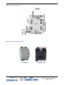
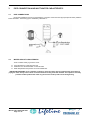
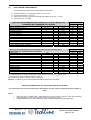
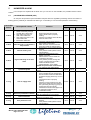
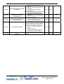
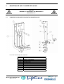
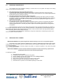
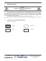
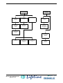
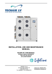
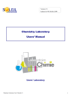
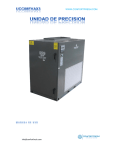
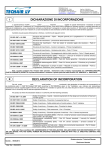
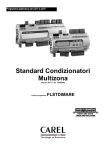
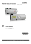
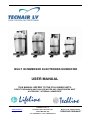
BUILT IN IMMERSED ELECTRODES HUMIDIFIER USER MANUAL THIS MANUAL REFERS TO THE FOLLOWING UNITS: DIRECT EXPANSION AND CHILLED WATER AIR CONDITIONERS WHIT ACCESSORY “INTERNAL HUMIDIFIER” www.tecnairlv.it [email protected] TECNAIR LV S.p.A Via Caduti della Liberazione 53 21040 UBOLDO (VA) Tel. +39029699111 / Fax +390296781570 Manual code 75803107B.0807 “VERSIONE ORIGINALE” Manual code 75803107B.0807 Page 2 of 24 INDEX 1 PURPOSE OF THIS MANUAL 5 2 COMPONENTS DESCRIPTION 6 3 PIPE CONNECTION AND INLET WATER CARACTERISTIC 8 3.1 3.2 3.3 8 8 9 4 OPERATING PRINCIPLES, CONTROL AND OTHER FUNCTIONS 10 4.1 4.2 10 10 10 10 11 11 11 4.3 4.4 4.5 5 6 7 8 PIPE CONNECTIONS WATER CIRCUIT CARACTERISTIC INLET WATER CARACTERISTIC ATER CONDUCTIVITY CONTROL HIGH LEVEL SENSOR 4.2.1 FOAM PRESENCE CONTROL CURRENT PEAK VALUE CONTROL DRAINING MODE 4.4.2 MANUAL DRAINING MODE PRE-WASH FUNCTION HUMIDIFIER ALARM 12 5.1 5.2 12 14 µAC MICROPROCESSOR (CP4) pCO MICROPROCESSOR MAINTENANCE AND CYLINDER REPLACING 16 6.1 6.2 6.3 6.4 16 17 17 18 HUMIDIFIER COMPONENT DESCRIPTION (MAINTENANCE) PERIODICAL MAINTENANCE REPLACING THE CYLINDER OTHER IDRAULIC COMPONENT MAINTENANCE TROUBLE ANALYSIS 19 7.1 19 CHECK AND SOLVE THE HUMIDIFIER PROBLEM NOTE 22 Manual code 75803107B.0807 Page 3 of 24 Manual code 75803107B.0807 Page 4 of 24 1 PURPOSE OF THIS MANUAL This handbook introduces you to the installation, use and maintenance procedure of the internal humidifier. In the following chapter we will explain some points of extreme importance so to allow you to use this unit in the best way. Therefore TECNAIR LV suggests you to take a deepened reading of this handbook. Some of the arguments refer to operation modality, components and accessories of the unit that are not described in this handbook. For these TECNAIR LV suggests to read the MICROPROCESSOR USE handbook, placed in the unit. If, after the reading of this handbook, you still find yourselves in a situation of difficulty do not hesitate to contact our after sales service: After sales office Tel. +39029699111/Fax +390296781570 @:[email protected] Manual code 75803107B.0807 Page 5 of 24 2 COMPONENTS DESCRIPTION The internal humidifier whit immersed electrodes are following made: N° 1 2 3 4 4a 5 6 DESCRIPTION Bearing frame Cylinder Drain solenoid valve 90° revolving drain connection Straight drain connection (optional) Conductimeter + Fill tank Fill solenoid valve Component details: N° 1 2 3 4 5 6 7 8 9 10 11 12 13 DESCRIPTION Fill solenoid valve Flow rate limit device Supply pipe Fill pope Overflow pipe Conductivity measuring electrodes Fill tank – overflow device* High level electrodes Steam outlet Elecrodes (2/6 mono-phase, 3/6 threephase) Cylinder casing Bottom filter Drain solenoid valve * Device used to avoid water overflowing from the fill tank above the safety level (for example if there are a malfunction of the controller or a likage on the fill valve). The fill tank is equipped whith an overflow septum that discharges the excess water through a special pipe. The overflow septum is located in a lower position then the fill one ( -40mm) to avoid back-flow into the fill pipe. Manual code 75803107B.0807 Page 6 of 24 µAC electronic regulation board: pCO elecronic regulation board end TAM: PCOUMID200 EXTERNAL TAM Manual code 75803107B.0807 Page 7 of 24 3 PIPE CONNECTION AND INLET WATER CARACTERISTIC 3.1 PIPE CONNECTIONS During the installation of the unit is requested the connection of the inlet water pipe (see picture below) whith the follow caracterisc. The draining pipe is installed by TECNAIR LV. 3.2 WATER CIRCUIT CARACTERISTIC These condition satisfy a good idric circuit: Line interrupted by a intercept water tap Installation of a mechanical filter on the inlet water Water temperature and pressure on the accettable limit IMPORTANT WARNING: upon installation completion, drain the supply pipe for approximately 30 minutes by piping the water direcly into the drain connection without sending it into the umidifier. This operation avoid any possible residual product that could clog the fill valve and/or produce foam during boiling. Manual code 75803107B.0807 Page 8 of 24 3.3 INLET WATER CARACTERISTIC The humidifier need normal water whit the following caracteristic: Pressare between 0.1 and 0.8 Mpa (1-8 bar, 14.5-116 PSI) Temperature between 1 and 40 °C Istant flow rate not lower than the fill solenoid valve rated flow rate (0.6 – 1.2 l/m) Connection type ¾”G Male LIMIT VALUES FOR MEDIUM-HIGH CONDUCTIVITY SUPPLY WATER OF A HUMIDIFIER WITH IMMERSED ELECTRODES Hydrogen ions Specific conductivity at 20 °C Total dissolved solids Dry residue at 180 °C Total hardness Temporary hardness Iron + Manganese Chlorides Silica Residual chlorine Calcium sulphate Metallic impurities Solvents, diluents, soaps, lubricants pH σR, 20 °C TDS R180 TH - µS/cm mg/1 mg/1 mg/l CaCO3 mg/l CaCO3 mg/l Fe Mn Ppm Cl mg/l SiO2 mg/l Cl mg/l CaSO4 mg/l mg/l LIMITS Min. Max. 7 300 (¹) (¹) 100 (²) 60(³) 0 0 0 0 0 0 0 8,5 1250 (¹) (¹) 400 300 0,2 30 20 0,2 100 0 0 LIMIT VALUES FOR MEDIUM-LOW CONDUCTIVITY SUPPLY WATER OF A HUMIDIFIER WITH IMMERSED ELECTRODES LIMITS Min. Max. Hydrogen ions Specific conductivity at 20 °C Total dissolved solids Dry residue at 180 °C Total hardness Temporary hardness Iron + Manganese Chlorides Silica Residual chlorine Calcium sulphate Metallic impurities Solvents, diluents, soaps, lubricants 7 125 (¹) (¹) 50 (²) 30(³) 0 0 0 0 0 0 0 pH σR, 20 °C TDS R180 TH - µS/cm mg/1 mg/1 mg/l CaCO3 mg/l CaCO3 mg/l Fe Mn Ppm Cl mg/l SiO2 mg/l Cl mg/l CaSO4 mg/l mg/l 8,5 500 (¹) (¹) 250 150 0,2 20 20 0,2 60 0 0 (1) Values depending on specific conductivity; in general: TDS ≅ 0.93 * σ20; R180 @ 0.65 * σ20 (2) not lower than 200% of chlorides content in mg/l of Cl(3) not lower than 300% of chlorides content in mg/l of ClWarning: no relation can be demonstrated between water hardness and conductivity. IMPORTANT WARNING! DO NOT TREAT WATER WHITH SOFTENERS! This could cause corrosion of the electrodes or the formation of foam, leading to potential operative problem or failure. Avoid: 1. 2. Using well water, industrial water or water drawn from cooling circuits; in general, avoid using potentially contaminated water, either from a chemical or bacteriological point of view. Adding disinfectants or corrosion inhibiters to water, as these substances are potentially irritant. Manual code 75803107B.0807 Page 9 of 24 4 OPERATING PRINCIPLES, CONTROL AND OTHER FUNCTIONS 4.1 ATER CONDUCTIVITY CONTROL The humidifier have a double control on the water conductivity. The first is made directly on the inlet water and the second on the cylinder water during the boiling. The inlet water conductivity value is compared with two alarm threshold for the pre- alarm end alarm of high conductivity. Is necessari don’t go over this threshold to not compromise the good working of the humidifier, in this case the software give a pre-alarm end if the problem continue stop completely the production. The second control is made direcly on the water of the cylinder. During the boiling and the evaporation the conductivity of the water increase for the concentration of the salts. This measuring is indirect by the reduction time of the current from the nominal value to the -5%. This time is compared whith a nominal one (one for each cylinder) and, if it is lower is make a draining (dilution draining) of a certain quantity of water and re-fill a lower conductivity fresh water. Shuld remeber that the value of conductivity under the I/O loop is the inlet water value and it is re-fresh at each filling phases. 4.2 HIGH LEVEL SENSOR The high level alarm can be made by one of the following problem: Total filling of the cylinder – whith humidifier OFF – foe a leakage on the fill solenoid valve For the high level on the first start-up filling For the cylinder full of limestone For the foam on the cylinder, totally indipendent by the water level For all of these problem the internal algorithm start a specific procedure to come beck to the normal working. On the last three case the humidifier start the low production phase. 4.2.1 FOAM PRESENCE CONTROL If the high level sensors are touched by the water, the internal function are not able to recognise if it is water or foam. If after few draining cycle and few stabilization cycle the sensors are already covered, then start the anti-foam cycle (if the alarm situation remain the umidifier start a complete washing cycle [complete draining Æ complete fill Æ complete draining]) If after the wasing cycle, the electrodes are already covered and another cycle is necessary, then the system give the alarm of PRESENCE OF FOAM. 4.3 CURRENT PEAK VALUE CONTROL Any time the humidifier is activated is possible see, for a short time, a big peak value of current. On the system, this peak value of current, can be accepted for the first 60 second whith this limitation: If the current is In*170% bigger then the nominal one, there are a HIGH CURRENT DRAINING. At the end of the draining the humidifier restart. On the first 60 sec. for the second time , or over the 60 sec. for the first time, if the current is In*150% bigger then the nominal one, there are a 30 second draining. At the end of the draining there are a “HIGH CURRENT” alarm. Over the 60 sec. if the current is alwais In*130% bigger then the nominal one. there are a HIGH CURRENT DRAINING for 5 seconds. At the end of the draining the humidifier restart. If the problem remain there are a “HIGH CURRENT” alarm. Manual code 75803107B.0807 Page 10 of 24 4.4 DRAINING MODE The draining is activated for depends on several factors (es. High level, high current , etc.) the difference between the draining type is the drain time. The type of draining (DRAIN_MODE) are the follow: 4.4.1 Set-point reduction draining. Drain for no current whith full cylinder. First high current drain Second high current drain on the first 60 sec. Drain before the enabling Default drain AUTOMATIC DRAIN MODE The humidifier have the follow automatic drain mode: Set-point reduction drain: during this mode, in case the reduction of the set-point is more then 33%, the humidifier drain a little bit of water. This function is usefull to produce immediately the right quantity of steam wen the set-point is drastically reduced. This function is always active. Inactivity drain: the inactivity drain is usefull to empty the cylinder when the humidifier don’t produce steam for a longer period (default 1 day). The function is actived by default, is possibile disabile and ch’ange the periode by the user loop. Periodic drain: During the normal working, if the water is heavy hardness, the humidifier empty the cylinder after a settable period (default 24 hours). This function is usefull to drain the limeston and increase the life of the cylinder. in modo da favorire la fuoriuscita dei sedimenti.The function is actived by default, is possibile disabile and ch’ange the periode by the user loop. Diluition drain under tension: During the steam production, the cumul of salt increase the internal conductivity and, for a good working, have to stay under certain limit. To make this the humidifier, in automatic way, make a little drain at the right time (called “Diluition drain”) and fill a new water with a lower conductivity. During this drein by default the power is stopped, in this way the drained water have not tension. In this little period the production is stopped. Is possible make the drain with tension, whith the main power on, disabling the parameter: Drain without tension. 4.4.2 MANUAL DRAINING MODE The manual draining is usefull durino the maintenance, and any other activity on the cylinder, to remove any presence of water inside the cylinder. The draining is different by the microprocessor installed: µAC: To make the comlete draining you have to press the apposite key inside the elecrical panel for minimum 120s (see electrical wiring diagam). pCO: To make the comlete draining you have to enable the apposite parameter on the maintenance loop for minimum 120s. At the end of the draining disabile the parameter. (See the use manual of the microprocessor). 4.5 PRE-WASH FUNCTION Is possible enable this function during the periodic maintenance. This function have two different working phases: Whith power OFF, the drain valve and the fill valve are opened for a certain time how depends on the cylinder capacity. This phase is necessary to clean-up the pipe and the solenoid valve. Three full filling phases and relative draining phases whith the power on. This phase is necessary to clean-up the wall and the electrodes of the cylinder. Manual code 75803107B.0807 Page 11 of 24 5 HUMIDIFIER ALARM In this chapter are explaned all the alarm how you can have on the humidifier, the possible reasons and the solution. 5.1 µAC MICROPROCESSOR (CP4) On the µAC microprocessor (CP4 humidifier board) the alarm are signalled by a flashing red led. The number of flashing give the possibility to understand the alarm type. In the table you can reach the explanation of the flashing. Red LED flashes 2 Short Description & causes Electrodes over-current: 1 Water conductivity too high (usually after a short stop) 2 High water level due to a drain valve malfunction 3 High water level due to a fill valve malfunction 4 Electrodes malfunction 3 Short Not current on the elecrodes: when the uniti s on the steam is not produced 4 Short Internal memory error 5 Short High conductivity on the inlet water 2 Long Cylinder depleted 3 Long Lack of supply water 4 Long Excessive production reduction 5 Long Drain malfunction 6 Long User parameters error Manual code 75803107B.0807 Page 12 of 24 Solution 1 2 3 Drain some water and re-start Verify if the fill valve is properly working Check for any leakage of the fill valve when the unit is OFF Check the esternal signal:Type (V o mA)? Value? Connection? 2 Swich OFF the unit, disconnect the power and check the internal wiring 1 Download the correct konfiguration by Humiset 2 If the problem remain please contact Carl assistance 1 Control the parameter B6 by the RS485 connection 2 Switch OFF the unit and wash the conductivity elecrodes 3 If the problem persists, change the source of supply water or install a suitable treatment system (demineralisation, even partial). NOTE: the problem will not be solved by softening the supply water. Do maintenance and/or replace the cylinder 1 Check that the fill pipe from the mains to the humidifier and the internal pipe are not blocked or bent and that there is sufficient supply pressure (0.1 to 0.8 MPa); 2 Check the fill valve is properly working; 3 Check for counter-pressure onto the steam hose higher than the maximum limit, preventing the entry by gravity of supply water into the cylinder; 4 Check that the steam outlet pipe is not is choked and that there is no condensate inside it Cylinder completely depleted or excessive foam. Do maintenance to the cylinder Check the drain circuit and the proper operation of the drain valve 1 Download the correct konfiguration by Humiset 2 If the problem remain please contact Carl assistance Alarm Type Reset Alarm relay Block Manual Active Block Manual Active Block Manual Active Block Manual Active Signal Manual - Disable Manual Active Disable Manual Active Disable Manual Active Block Manual Active 1 Check the conductibility of the supply water 2 Check the limit set by parameter b5 via RS485 3 If necessary, install a suitable demineralizer. NOTE: the problem will not be solved by softening the supply water. 1 Check the connection to the external regulator 2 Check the settings of parameters A0 and A2 via RS485 With the OEM turned off: 1 Check for any leaks from the fill valve or the condensate return pipe 2 Check that the level sensors are clean Foam is usually caused by surfactants in the water (lubricants, solvents, detergents, water treatment agents, softeners) or an excessive concentration of dissolved salts: 1 Drain and clean the water supply pipes 2 Clean the cylinder 3 Check for the presence of softeners (in this case, use another type of supply water or reduce the softening) Do maintenance and/or replace the cylinder 1 7 Long Supply water high conductivity pre-alarm 8 Long External command signal not properly connected (only 2 to 10V) 9 Long Cylinder full with production not in progress 10 Long Foam inside the cylinder 11 Long Cylinder almost completely depleted Signal Manua - Disable Manua Active Disable Manual Active Signal Manua - Signal Manua - Manual code 75803107B.0807 Page 13 of 24 5.2 pCO MICROPROCESSOR On the pCO microprocessor the alarm reaching is automatic by the software. The problem are explaned in the alarm mask of the display. In the follow table are explaned the type of alarm: ALARM CAUSES SOLUTION RESET ACTION Check the pressure of the fill pipe water (0.1÷0.8 MPa, 1÷8 bar); Check the fill valve state; Check if the steam pipe haven’t a high counterpressure or a narrowing passage Manual Production stopped Cylinder full of limestone or too high foam. Make the maintenance of the cylinder Manual Production stopped Check the drain valve or the drain pipe Manual Production stopped Check and wash the conductivity sensor and, if the problem persist, change the type of water quality NOTE : The problem are not solved by the water softeners. Manual Production stopped It appear at the follow situations: 1 During the fill state. 2 If the difference between the initial current and the measuring current Low current Whit the unit OFF and the main power OFF is different of a limit calculed by alarm check the internal wiring connection the target current, or if is at full 3 If the water touch the high level 4 If the current is minor then a limit calculated on the target current Manual Production stopped It appear at the follow situations: 1 If before 60 seconds there are one second peack of current over the 150% of the nominal, there are a 1 High current draining of 30s. At the and of the 2 alarm draining the Humidificator was stopped and the unit give the 3 alarm. 2 If, over the first 60s, the current reach the 130% of the nominal. Manual Production stopped This alarm incoming: 1 Cylinder empty of water Low production alarm 1 2 During the fill if: • The maximum fill time is spired • If there are a strange value. If during the pre-wash the water level don’t tuch the high level electrodes. This alarm incoming if, durino the low production phases, the current at the end of the filling is lower then a calculated threshold. 2 3 This alarm incoming during the drain: Drain alarm 1 2 If the current do not decrease; If during a foam problem or a prewash the water tuch the high level sensor. This alarm icoming if the threshold are High exeed for 60 minute during the conductivity production or immediately if the water alarm supply conductivity are 3 time bigger then the threshold. Manual code 75803107B.0807 Page 14 of 24 Check the drain valve working Check if there are some lickages on the fill valve Drain some water and restart the unit This alarm incoming: 1 Foam alarm 2 If after a the anti-foam cycle (Drain Æ Fill Æ Drain) the water tuch the high level sensor; If after a complete washing the high level sensor are already tuched. 1 Wash the fill pipe 2 Wash the cylinder 3 Check the presence of a salt reducer and disable them Manual Production stopped Manual Production stopped This alarm incoming if the water tuch the high level sensor when: Cylinder full 1 of water 2 Check if the fill valve have no lickage or the the unit is in OFF position or the elecrodes are clean. humidifier is disabled; the first phase of the pre-wash are not finished This alarm incoming if after some Full cylinder cycle of stabilizing the production pre-alarm parameter are higher that certain internal parameter. Make the periodical maintenance Manual Only signal This alarm incoming if after 3 hours Full cylinder after the full cylinder pre alarm the alarm parameter are already over the threshold Change or wash the cylinder Manual Only signal Manual code 75803107B.0807 Page 15 of 24 6 MAINTENANCE AND CYLINDER REPLACING CAUTION! BEFORE ALL WORKS PUT THE MAIN SWITCH IN POSITION “O” 6.1 HUMIDIFIER COMPONENT DESCRIPTION (MAINTENANCE) In the table are descripted the component: N° 1 2 3 4 5 6 7 8 9 10 11 12 Manual code 75803107B.0807 Page 16 of 24 DESCRIPTION Main structure Cylinder blocking system Fill box + conductimeter Full pipe Cylinder fill pipe Fill box pipe Fill valve Fill/drain group O-Ring 90° revolving drain connection Straight drain connection (optional) Drain valve 6.2 PERIODICAL MAINTENANCE The humidifier need some periodical checking to increase the life of the cylinder and improve the working modus. The checking are be made as follow: Every fortnight and no more than 300 working hours For both the disposable and openable cylinders, check that no significant water leak is present and verify cylinder operation and the general conditions of the container. Also check that no arc or spark originate between the electrodes when the machine is operating. Every three months and no more than 1,000 working hours For disposable cylinders, verify cylinder operation, check that no significant water leak is present and replace the cylinder, if required. For openable cylinders, check the container for markedly blackened areas: in case they are present, check the scale condition of the electrodes and, if necessary, replace them together with the Orings and the cover gasket. Every year and no more than 2,500 working hours For disposable cylinders, replace the cylinder. For openable cylinders, check that no significant water leak is present, verify cylinder operation and the general conditions of the container. Also check the container for markedly blackened areas: in case they are present, replace the electrodes together with the O-rings and the cover gasket. After extended use or due to the use of water with a high salt content, the solid deposits that form naturally on the electrodes might spread until they cover the cylinder internal wall. In case particularly conductive deposits form, the heat consequently produced might overheat plastic and melt it; in the most severe cases, heat might perforate plastic, causing the water to leak from the cylinder to the tank. As a precaution, check the quantity of deposits and verify that no deformation or blackening is present on the wall of the cylinder, otherwise replace it. 6.3 REPLACING THE CYLINDER IMPORTANT WARNING: the cylinder might be hot: before touching it, let it cool or use protective gloves. The duration of the cylinder depends on different factors, including: complete filling with limestone and/or partial or total corrosion of the electrodes, proper use and dimensioning of the humidifier, working output, water quality, careful and regular maintenance. After a variable period is necessary replace the cylinder. To made this operation in the proper way please respect the following instruction. IMPORTANT WARNING: all service and/or maintenance operations must be carried out by specialist and qualified personnel aware of the necessary precautions. To replacing the cylinder: 1) 2) 3) 4) 5) 6) 7) Place the unit in OFF position Completely drain the water contained in the cylinder Turn the appliance off and open the mains knife switch (safety procedure) Remove the steam pipe from the cylinder Disconnect the electrical connections from the top of the cylinder Release the cylinder from the fasteners and lift it for removal Assemble the new cylinder on the humidifier operating in reverse order. Manual code 75803107B.0807 Page 17 of 24 6.4 OTHER IDRAULIC COMPONENT MAINTENANCE WARNING: 1) 2) 3) For the plastic component washing do not use solvent or aggressive agent; To remove the limeston you can use vinegar or vinegar acid at 20%, after you can wash whit water. After the changing or the control of the component please check if all the connection are made in the right way. Start-up the unit and make some pre-wash cycle, then check if there are some water filling. Filling valve: Disconnect the pipe and the elecric wire, remove the valve and check if the filter are clean; If necessary, wash it whit water and a soft brush. Fill/Drain group: Chek and wash the cylinder connection whith water. Check the O-ring status; if necessari change it. Draining valve: Disconnect the elecric wire and the draining pipe, remove the valve by the screw, wash it whit water and a soft brush. Fill box and conducimeter: Check if there are some limeston iside the connection and on the elecrodes; Wash it whit water. Fill and high level pipe: Check if there are some limeston iside and wash it whit water. Manual code 75803107B.0807 Page 18 of 24 7 TROUBLE ANALYSIS CAUTION! BEFORE ALL WORKS PUT THE MAIN SWITCH IN POSITION “O” The following chapter aims at assisting the operator in searching possible troubles in the unit equipment. Starting from the type of problem in question, indication is given of the possible sequential causes of the trouble itself and the possible remedies. The description of the causes is general, so it takes into consideration the most complete possible versions of the units; the operator shall take care to identify, from time to time, only the matters of interest and/or the functions actually featured in the unit in question. Any intervention on the unit shall be carried out only by competent skilled personnel. We recommend not executing any kind of operation if you have not enough knowledge of the unit working principle. 7.1 CHECK AND SOLVE THE HUMIDIFIER PROBLEM Legend of the failure diagram: FAILURE FUNCTION CAUSE REMEDY Manual code 75803107B.0807 Page 19 of 24 NON WATER CHARGING LACK OF TENSION IN CHARGING SOLENOID FAILURE OF THE CHARGING VALVE SOLENOID CHE CK THE HUMIDIFIER‘S ELECTRONIC CARD DISCONNECT AND REPLACE THE SOLENOID SHORTCIRCUITED CYLINDER LACK OF WATER TOO CONDUCTIVE WATER PROVIDE A SOFTENER ACCORDING TO THE ACCEPTED VALUES CHECK THE CONTACTOR’S CONSENT PRESENCE OF POLYPHOSPHATE MEASURING DEVICES CHECK WATER TAPS Manual code 75803107B.0807 Page 20 of 24 CLEAN PRESSURE REDUCER AT CHARGING VALVE OUTLET CLEAN WATER CHARGING VALVE FILTER ELIMINATE MEASURING DEVICES CONTINUOUS WATER DISCHARGE FOAM IN THE CYLINDER TOO FULL CYLINDER DUE TO MAGNETOTHERMIC SWITCH INTERVENTION TOO FULL CYLINDER DUE TO LOW WATER CONDUCTIVITY MANUALLY DISCHARGE THE CYLINDER MANUALLY DISCHARGE AND RESTORE THE MAGNETOTHERMIC SWITCH LACK OF BOIL OPEN DISCHARGING VALVE DISC PUT SALT IN THE FILLING BAC CLEAN SOLENOID AND FILLING BAC CHECK WATER TAPS TOO FULL CYLINDER MAGNETOTHERMI C SWITCH INTERVENTION MANUALLY DISCHARGE AND RESTORE LACK OF WATER CLEAN FILTER AND WATER DISCHARGING VALVE OPEN DISCHARGIN G VALVE DISC MANUALLY DISCHARGE AND RESTORE THE MAGNETOTHERMIC SWITCH DEFECTIVE DISCHARGING VALVE SOLENOID DISCONNECT THE SOLENOID AND REPLACE IT RUN-DOWN CYLINDER DISCONNECT AND REPLACE THE CYLINDER CLEAN SOLENOID AND DISCHARGING VALVE THE WATER RUN OVER THE BAC NON WATER DISCHARGE LOW WATER CONDUCTIVITY MAGNETOTH ERMIC SWITCH INTERVENTIO N LACK OF TENSION IN DISCHARGING SOLENOID CHECK THE HUMIDIFIER’S ELECTRONIC CARD CLOGGED AND COUNTERINCLINED DISCHARGING PIPELINE VERY SMALL DISCHARGING PIPELINE CLEAN AND ELIMINATE THE COUNTERINCLINATION DISCONNECT AND REPLACE THE PIPELINE Manual code 75803107B.0807 Page 21 of 24 8 NOTE Manual code 75803107B.0807 Page 22 of 24 Manual code 75803107B.0807 Page 23 of 24 Manual code 75803107B.0807 Page 24 of 24