1
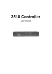
MPBB1 Uploader
P/N 35000011
user manual
© 1997 - 1999 Martin Professional A/S, Denmark.
All rights reserved. No part of this manual may be
reproduced, in any form or by any means, without
permission in writing from Martin Professional A/S,
Denmark.
Printed in Denmark.
P/N 35000011, Rev. B, 990611-MA
section 1
I N T RO D U C TI ON
Thank you for selecting the Martin MPBB1 Uploader. The MPBB1 is a “multi-purpose
black box” that works together with the Martin Software Uploader program to allow you
to update software and adjust settings on selected Martin fixtures remotely via the serial
link
Please familiarize yourself with this manual before using the MPBB1.
Sa fe ty p r ec au ti on s
•
The MPBB1 is NOT for household use.
•
Always unplug from AC power when replacing the fuse or removing any
cover.
•
For protection against fire and electrical shock, ensure that the fixture is
properly grounded (earthed), and do not expose it to rain or moisture.
•
Do not block air vents.
•
Refer service to a qualified technician.
S u p p o r te d M ar t i n p ro d uc ts
The MPBB1 currently supports the following Martin fixtures:
•
Exterior 600
•
MAC 250
•
MAC 300
•
MAC 500
•
MAC 600
•
RoboScan Pro 918
F ea tu r e s
•
•
•
•
•
•
•
4-digit LED control panel
3-pin and 5-pin locking XLR data output jacks
Rear panel 115/230 V selection
Compact design for easy portability
Rugged steel construction
Standard IEC power socket
On/off switch
3
section 2
SE T UP
The MPBB1 package includes
•
MPBB1 Uploader
•
Power cable
•
9-pin to 25-pin RS-232 cable
•
User manual
Powe rin g th e MP B B1
WA R N I N G !
For safe operation, the MPBB1 must be grounded (earthed).
C he ck vo l t ag e se t t i ng
The MPBB1 may be switched between 115 and 230 V. Make sure the switch, located on
the back of the unit, is correctly set before applying electricity.
I n s t al l pl ug
The fixture may be delivered without a plug on the power cord. Install an approved 3prong grounding type plug per the manufacturer’s instructions, connecting the wires to
the pins as shown below. The table shows some possible pin identification schemes. If the
pins are not clearly identified, or if you have any doubts about proper installation, consult a qualified electrician.
Wire
Pin
Marking
Screw (US)
brown
live
“L”
yellow or brass
blue
neutral
“N”
silver
yellow/green
ground (earth)
green
App ly power
Plug the power cord into the MAINS INPUT socket and the AC outlet. To turn on the fixture, flip the power switch to the “I” position. To turn it off, flip the power switch to the
“O” position.
When powered on, the MPBB1 displays the version of its firmware and the type and version of fixture software loaded in memory.
4
section 3
D OW N L OA D IN G T O TH E M P B B 1
UPLd
PC
FIXT
FACT
Fixture software updates (MU2 files) are available from your Martin dealer or the Martin
web site at http://www.martin.dk. The software must be transferred to the MPBB1 from
your Windows PC via the COM port using the Martin Software Uploader program. The
MPBB1’s memory holds 1 fixture file at a time.
C o n n ec t t h e M P B B 1 to a W i n dow s P C
The MPBB1 connects to the computer with an RS-232 serial link cable wired straight
through, i.e., RXD to RXD, TXD to TXD, and SG to SG. A 9-pin to 25-pin cable is provided. If your computer has a 9-pin serial (COM) output, construct or obtain a cable with
9-pin female DSUB connectors on both ends. The cable connections are shown below.
9-pin to 25-pin
serial cable
9-pin to 9-pin
serial cable
9-pin 25-pin
female
female
2 RXD TXD 2
3
3
SG
5
7
4
5
6
9-pin 9-pin
female female
2 RXD 2
3 TXD 3
SG
5
5
1.
With the power off, connect the 9-pin RS-232 connector to the MPBB1.
2.
With the power off, connect the 25-pin RS-232 connector to the computer’s serial COM port.
3.
Turn on the MPBB1 and the computer.
D ow n l o a d M U 2 f i l e
1.
Start the Martin Software Uploader.
2.
Click on Setup. Click on Hardware.
3.
Select the COM port. Make sure that no other devices such as a mouse
or modem are using the selected port. The verify function confirms the
presence of the COM port and checks that no other drivers are using
the same port, but it does not check the actual connection to the
MPBB1.
5
6
4.
Click on OK.
5.
Click on Download Software to the MPBB1.
6.
Select fixture type.
7.
Click on Get File, select the MU2 file to download, and click on Open.
8.
Click on Download Software.
9.
Press [Menu] on the MPBB1.
10. Select PC from the MPBB1 menu. Press [Enter] to continue.
11. Click on Go.
12. Wait for the software to download to the MPBB1.
13. Exit the Martin Software Uploader.
7
section 4
U P L OA D I N G T O F IX T U R E S
UPLd
dMX
MART
boot
C o n n ec ti n g t he M P B B 1 to t he s er i a l l i n k
1.
Connect the MPBB1 to the fixture or serial link as if connecting a controller. Both the 5-pin and 3-pin XLR outputs are wired to the DMX-512
standard, but may be configured to the Martin standard if desired. See
section 6 for details.
2.
Power up the fixtures and allow them to reset. Turn on the MPBB1.
D M X / M ar t i n m o d e u pl oa d
1.
Use the arrow keys to select UPLd from the MPBB1 menu. Press
[Enter] to continue or [Menu] to escape.
2.
Select DMX or Martin protocol. If the fixtures are set for auto protocol
detection, either protocol may be used. If not, the protocol must match
the fixture PSET setting. If neither DMX or Martin upload is possible,
boot mode can be used. See below.
3.
Press [Enter]. The MPBB1 tells the fixtures they are about to receive
software; the fixtures respond by displaying boot. When the upload finishes, the MPBB1 displays dONE and the fixtures reset.
B o o t m od e u p l o ad
If an upload is interrupted, the fixtures must be powered off for at least 10 seconds before
a new upload can be attempted. When powered on, they automatically go into boot mode,
ready for a second upload attempt; skip step 1 below. If necessary, a fixture can be set to
boot mode from its control panel, or if the software is corrupted, by setting jumpers on
the circuit board - see the fixture manual.
1.
8
Set the fixture to boot mode per the fixture manual.
2.
Select UPLd from the MPBB1 menu. Press [Enter] to continue.
3.
Select boot mode on the MPBB1. Press [Enter] to continue.
4.
The MPBB1 tells the fixture it is about to receive software; the fixture
responds by displaying boot. When the upload is finished the MPBB1
displays dONE and the fixture resets with the new software. If jumpers
were moved, remember to return the jumpers to their original position.
section 5
SE T T I NG F I X T U R E PE RS ON A L IT IES
After uploading - the fixture and the MPBB1 must have identical software in memory - a
subset of fixture settings are remotely adjustable just as if setting the fixture from its control panel. Refer to the fixture manual for personality setting information.
Settings can be changed on all fixtures of the type on the link, or just 1. It is not possible
though to distinguish between fixtures with the same address.
Some changes, such as protocol settings, do not take effect until the fixture is powered up
again. This is to avoid communication failure due to a change of protocols.
To help find an unknown fixture address when using DMX protocol, the MPBB1 causes
the fixture to light when an address is within the fixture’s address space. To find the start
address, scroll through the addresses until you find the lowest address at which the fixture
responds by opening the light. (The lamps must warm up before you can see them.)
To indicate the current mode, 2 decimals flash in the display to indicate DMX or Martin
protocol, and whether a single fixture or all fixtures are selected.
e
gl
X
M
D
tin
ar
M
l
Al
n
Si
The uploader does not receive data from the fixtures; readouts such as lamp hours and
settings requiring feedback are therefore not supported. Settings cannot be read remotely
so you may want to restore some or all of the settings to their factory defaults before
making adjustments. The MPBB1 offers a convenient way to do this.
R es to r e fa ct o r y d ef au l t s
FACT
1.
FAC1
FAC2
FAC3
FAC4
dMX
MART
ALL
SING
address
Select FACT from the MPBB1 menu. Press [Enter] to continue or
[Menu] to escape.
9
2.
Select the restore level (see below). Restoring all fixtures to the factory
default address (FAC3 and FAC4) sets the address on all fixtures to 1 .
Restore
Level
Address
Protocol
Offsets
All Others
FAC1
no
no
no
yes
FAC2
no
no
yes
yes
FAC3
yes
yes
no
yes
FAC4
yes
yes
yes
yes
3.
Press [Enter] to continue.
4.
Select DMX or Martin protocol. Press [Enter] to continue.
5.
Select ALL to restore all fixtures (of the type) on the link, or SING to
set a particular fixture. Press [Enter] to continue.
6.
If restoring a single fixture, select the address with the up and down
keys. Press [Enter] to restore.
7.
Confirm by pressing [Enter], or press [Menu] to escape.
S e t pe rsona li tie s
FIXT
10
dMX
MART
ALL
menu
SING
address
menu
1.
Select FIXT from the MPBB1 menu. Press [Enter] to continue or [Menu]
to escape.
2.
Select DMX or Martin protocol. Press [Enter] to continue.
3.
Select ALL to set all fixtures (of the type) on the link, or SING to set a
particular fixture. Press [Enter] to continue.
4.
If you selected SING, select the fixture start address. Use the up and
down keys to scroll through the addresses. Press [Enter] to continue.
5.
Set the fixture(s) as you would from the control panel. Scroll through
menus with the arrow keys, select items by pressing [Enter], or escape
by pressing [Menu]. A few settings, such as fixture address, require an
extra confirmation - press [Enter] when SURE is displayed to set the
value.
section 6
B AS I C S E R V I C E
WA R N I N G !
Ensure the MPBB1 is unplugged before performing these
procedures.
C h an g i n g t he f us e
1.
Unplug the MPBB1.
2.
Remove the 2 screws from the top near the air vent and the 4 screws
from the front.
3.
Lift off the cover.
4.
Locate and replace the fuse with one of the same rating. The rating is
shown on the serial number label.
5.
Replace the cover.
C h an g i n g t he X LR p i n - o u t
2
-
2
-
+
3
+
3
Martin pin-out
DMX pin-out
1.
Unplug the MPBB1.
2.
Remove the 2 screws from the top near the air vent and the 4 screws
from the front.
3.
Lift off the cover.
4.
Locate the 2 jumpers labelled “PL07” and “PL08” behind the 3-pin XLR
output.
5.
Position the jumpers as shown above and push them all the way down.
6.
Replace the cover.
11
appendix a
TRO UBL E S HOOT IN G
problem
The unit appears dead.
Fixture(s) do not to
respond to the MPBB1.
Software Uploader cannot download to
MPBB1.
probable cause(s)
suggested remedy
Power off.
Apply power.
Blown fuse.
Replace fuse.
Incorrect voltage setting.
Set voltage switch to
match AC supply.
Link polarity reversed.
Swap pins 2 and 3
between the fixture and
the MPBB1. (See fixture manual or section
6.)
The MPBB1 is set to
DMX and the fixture
(PSET) is set to Martin,
or vice versa.
Select the same protocol as the fixture.
No or wrong software
loaded in MPBB1.
Power up the MPBB1 to
check fixture type.
Download the correct
software.
Defective data link.
Check the data link by
connecting it to a controller; correct if necessary.
Bad RS-232 connection.
Check connection.
Wrong COM port
selected.
Select correct COM
port.
COM port conflict.
Select another COM
port.
If the suggested remedies do not solve the problem, contact your Martin dealer for service.
12
appendix b
SP E CI F I CAT I ON S
D im en si o n s
•
•
•
•
Length ..................................................................... 130 mm
Width ........................................................................181 mm
Height ........................................................................ 72 mm
Weight ........................................................................ 1.1 kg
(5.1
(7.1
(2.8
(2.4
in)
in)
in)
lb)
E l ec t r ic a l
•
•
•
•
•
Power supply settings ............................115/230 V, switch selectable
Power consumption .....................................................................5 W
Current ..................................................................... 30 mA at 230 V
AC frequency .................................................................... 50 - 60 Hz
Fuse .........................................................0.315 A, time delay, 250 V
Construction
•
•
Housing .................................................................................... steel
Finish .................................................... electrostatic powder coating
C onne c t io ns
•
•
•
Power ............................................................................ IEC 3-prong
RS-485 ............................. 3 and 5-pin XLR, pins 2 and 3 switchable
RS-232 ...........................................................................9-pin DSUB
13
Martin Professional A/S
Olof Palmes Allé 18
DK-8200 Aarhus N, Denmark
Phone: +45 8740 0000
Internet: http://www.martin.dk