1
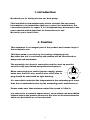
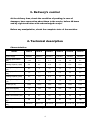
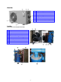
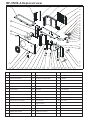
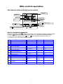
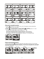
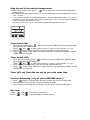
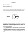
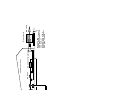
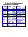
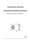
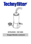
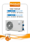
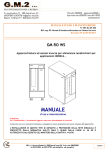
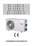
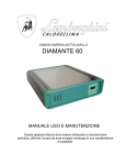
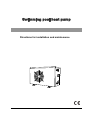
Directions for installation and maintenance contents 1. Introduction ………………….…………………………….……..………….p3 2. Caution …………………………………………………….………………….…..p3 3. Delivery control …………………………………………........................p4 4. Delivery control …………………………….………………………………..p4 Technical characteristics Outside Inside explored view Wire control operation General diagram of the refrigerating circuit Safety and control systems Electric diagram 5. Installation ……………………….………………………………….......p14 Rules of installation Hydraulic connections Electric connections Procedure of use 6. Water flow and refrigerating circuit pressure........................p18 7. Defrosting ……………………………………………………………………p19 8. Environment problem ………………………………………............p19 9. Error messages and what to do 2 ………………………………..…p20 1- Introduction We thank you for having chosen our Heat pump. This installation and maintenance notice contains the necessary information to its installation (delivery control, the installation, the connections) and to its repair. It is a complementary document to the user’s manual which describes its instructions for use. We invite you to read it first. 2- Caution This document is an integral part of the product and it must stays in the technical room. This Heat pump is exclusively for heating swimming pools. Any other use not in conformity and random will be considered as dangerous and unsuitable. The assembly, the electric connection and the start up must be carried out by specialized and professional person. When connect plug to socket (power supply), please make sure that live wire, neutral wire, earth wire to plug should be connected as right drawing. (L) (N) 16A 250V~ It is essential to maintain the temperature in the swimming pool lower than the recommended value by the swimming pool’s manufacturer. Please make sure that minimum water flow speed is 3.5m³/h. In a concern to a constant improvement, our products can be modified without notice; the present pictures in this note or the characteristics which are described are not contractual. 3 3- Delivery’s control At the delivery time, check the condition of packing; in case of damages, have reservation about them to the carrier, before 48 hours and by registered letter with acknowledged receipt. Before any manipulation, check the complete state of the machine. 4- Technical description Characteristics: MODEL 50HS-A 85HS-A 100HS-A 130HS-A 160HS-A 210HS-A 230/50/1 230/50/1 230/50/1 230/50/1 230/50/1 380/50/3 Heating Input Power * (kW) 1.05 1.7 2.1 2.6 3.5 4.3 Heating Capacity *(kW) 5.5 8.5 10.5 13 17.5 22.5 Heating Running Current *(A) 5.2 8 10 13 17 7*3 Cooling Input Power * (kW) 1.0 1.7 2.0 2.5 3.5 4.2 Cooling Capacity *(kW) 4.0 7.2 8.2 10 14 17 5 8 10 12 17 7*3 Air flow (m3/H) 1600 2000 2400 2500 3400 4000 Noise level (d(B)A) <51 <53 <55 <56 <58 <60 R410a R410a R410a R410a R410a R410a Water Connection*(mm) 50 50 50 50 50 50 Net weight of the unit (kg) 50 54 65 80 112 128 95*30*55 95*30*55 100*30*60 100*30*69 112*43*79 122*43*95 Power supply Cooling Running Current *(A) Refrigerant gas Overall sizes L x W x H (cm) * possible variations of value according to climatic conditions 4 Outside: 1 2 3 4 5 6 7 8 Inside: (Front sheet cover and panel removed) 9 10 11 12 13 14 15 16 17 18 Evaporator Fan Compressor High and low pressure interruptor Titanium heat exchanger Temperature sensor of swimming pool water Four way valve Ambient temperature sensor Defrost sensor Water flow switch 5 Fan protection grid ( blow side ) Metal cabinet Control panel Refrigerant charge valve Refrigerant pressure manometer Fast connection for water outlet Wire connection for power supply Fast connection for water intlet BP- 85HS- A Ex plored view 41 40 39 38 37 36 35 34 33 42 32 31 43 30 29 28 44 27 26 25 24 45 23 22 21 20 1 19 2 3 4 5 6 7 8 9 10 11 12 13 14 15 16 17 18 1 Fa n protection net 17 Po we r cord 33 Co mpr essor capacitor 2 Fr ont panel 18 Ri ght rear board 34 Fr ame 3 Co ntrol panel cover 19 Re frigerant charge valve 35 Ca pillary 4 Wire controller 20 Pr essure man omet er 36 Re ar net 5 Verge board polyfoam 21 Fa st connection 37 Co ndenser 6 Verge board 22 Gas ket 38 Co ndenser top polyfoam 7 Ex haust pipe 23 Termi nal 39 Left carriage 8 Fo ur wa y valve 24 Pu blic termi nal 40 Left net 9 Co mpr essor 25 El ectrical box 41 Top cover 10 Hi gh pressure interruptor 26 Transformer 42 Mot or bracket 11 27 Ci rcuit board 43 Fa n mot or 12 Water flow swi tch 28 Co pper sensor 44 Fa n 13 Gas returning pipe 29 Water sensor 45 Drain tube 14 Titanium heat exchanger 30 Ambi en t sen sor 15 Ru bber wa ter fender 31 Co mpr essor sensor 16 Ri ght size board 32 Mot or capacitor Low pressure interruptor Wire control operation The function of the LCD display and control: Heating mode (‘SUN’symbol) Cooling mode (‘SNOW’symbol) S ET LCD srceen T EM P water outlet temp. Parameter valve wat er set t ing t emp. Timer on Timer off Digit no. Pr ess t o t ur n on and t ur n of f t he unit s. Press button to choose cooling or heating mode Press this button 3 seconds to set or review data. Press Press M to start timer on / timer off. seconds 3 to checktemperature. coercive defrosting Press to set and check the operation data. Set the operation parameter: "button 3 seconds to enter operation parameter setting interface. When the unit stops, press" "again to start setting(parameter from 0-11, see Operation Parameter Table). ◎ Press" ◎ Under parameter setting, press " " or " " to set data for parameter from 0-11. ◎ No press in 10s, it will exit the setting interface. NO 0 1 2 3 4 5 6 7 8 9 10 11 Meaning Range Change Max. setting water temperature Defrosting start temperature Defrost exit temperature Turnround of defrosting Under heat mode Time of exit defrost Under heat mode Compressor protection Exhaust temperature Temperature of electrical valve switch on Water pump mode Automatic restart Mode (heat/coo & heat/cool/two tank) Water temperature difference to restart Water pump/Condenser heater 0/1 (5 ~ 45/60°C) -20 ~ 10°C 5 ~ 45°C Not change Can change Can change Can change 30 ~ 150 min 1 ~ 15 min 70 ~ 110°C Can change Can change No use 0 ~ 60°C 0/1 0/1 No use Not change Suggest not change Can change 0/1/2/3 1 ~ 10°C 0/1 Not change 7 Factory setting 0 (5 ~ 45°C) -7°C 12°C F0 (45 min) 2 min 95°C 7°C 1 1 1 3°C 0 Parameter 2 P a ra m e te r 1 Parameter 0 to set the max setting water temperature. (5~45/60 C) factory setting: 5~45 C. defrosting exit temperature (5~45 C) factory setting: 12 C to set the defrosting start temperature under heating mode (-20~10 C) factory setting:-7 C P a ra m e te r 6 P a ra m e te r 5 P a ra m e te r 4 temperature of solenoid valve switch on (0~60 C) factory setting: 7 C com p res sor protec tion e xh a u st te m p e ra tu re (70 ~110 C ) fac to ry s etting: 95 C tim e of de fro sting (1-15 m in) factory setting: 2 m in. M M Parameter 9 Parameter 8 Parameter 10 Mode: 0(heating only) 1(cooling and heating) 2(heating only) 3(2 tank) AUX factory setting: 1 a uto ma tic re sta rting (0/1) factory setting: 1 Water te m perature d iffere nce to res tart unit 1 ~ 10 C factory s etting: 3 C Parameter 3 Turnround of defrosting (30 ~ 150min.) M factory setting: 150 min. Parameter 7 water pump mode: 0: already open 1: 30s start before compressor start 30s stop after compressor stop. M Parameter 11 Mode: 0(water pump) 1(condenser heater) factory setting: 0 Choose the operation mode: ◎ Press “ ” to power on unit. Under running, the LCD displays the water setting temp, water temperature and current mode. ◎ Press “ ” to choose mode(mode can be changed under running) ◎ Press “ ” to set temperature 1 °C higher, press “ ” to set temperature 1 °C lower. ◎ The temperature setting range of water heating is 5 °C ~ 45°C . The temperature setting range of water cooling is 5 °C ~ 40°C . When water temperature reaches to setting temperature, the unit will stop; the unit has to restart when water temperature drop 3°C on HEATING mode. the unit has to restart when water temperature increase 3°C on COOLING mode. C o o l i ng m o d e M H e a ti ng m o d e M Check current temperature: ◎Under running, press “ ” 3 seconds to check the current status of the unit. You can check water/ambient/compressor/condenser temperature. If no buttons are depressed within 10 seconds, the LCD will display water-setting/water temperature. When the unit is switched off, current water temperature is displayed. W a te r outlet te m p . compressor exhaust temp. Ambient te m p . Condenser te m p . M M M 8 Stop the unit in low ambient temperature: ◎when the unit is OFF mode, press “ ” button 3 seconds to enter ambient temperature setting interface. ◎the range of stop temperature is from -15°C to 97°C,the range of restart temperature is from -13°C to 99°C. ◎ –F on left panle means -15°C (stop temperature), -d on the right panel means -13°C (restart temperature). The unit will stop when ambient temperature is -15°C, and the unit will restart when ambient temperature increase to -13°C. the display panel show “ EE C “ when ambient temperature drop down to -15°C. M Timer switch ON: 1. When the unit stops, press “ ” botton to set time for TIMER ON, press the botton again once to cancel the TIMER ON. Press “ ” and “ ” to set the time interval of 1 hour in a cycle manner : 1,2…24 2. When it reaches the switch-ON time, the unit will operate in the pre-set modes. 3. Press “ ” botton under TIMER ON setting, then the unit will start immediately, and the TIMER setting is cancelled. Timer switch OFF: 1. When the unit is running, press “ ” botton to set time for TIMER OFF, press the botton again once to cancel the TIMER OFF. Press “ ” and “ ” to set the time interval of 1 hour in a cycle manner: 1,2…24 2. When it reaches the switch-OFF time, the unit will automatically stop. 3. Press “ ” botton under TIMER OFF setting, then the unit will stop immediately, and the TIMER setting is cancelled. Timer OFF and Timer ON can not be set at the same time. Coercive Defrosting ( only on water HEATING mode ): 1. press “ ” botton 5 seconds when the unit is running, the unit go to defrost state. 2. When the defrost time reaches 2 minutes, defrost is stopped. 3. After exiting the defrosting, the unit will stop 1 minute, then it will heat water again. Key lock: Press “ Press “ ” and “ ” and “ ” 5 seconds, to set keylock. ” 5 seconds again to release keylock. 9 General diagram of the refrigerating circuit The heat pump is reversible allowing the swimming-pool’s heating or cooling: Swimming-pool water’s heating mode: The cold and liquid refrigerant fluid absorbs the heat contained in the air through the evaporator (gilled radiator), in which it is vaporizing; it is then put up in pressure and in temperature by the compressor which sends it in the condenser (exchanger) where it loses its heat (in giving it to the water of swimming pool) and comes back in liquid state; it loses its pressure and still cools in the expansion capillaries before turning back to the evaporator for a new cycle. Hot air Evaporator (gilled radiator) Single way valve Cold air Expansion capillary Pressure and gas intake 4 way valve Hot water Cold water Compressor Condenser (exchanger) 10 Swimming-pool water’s cooling mode: The 4 way valve reverses the circulation of the refrigerant fluid; the fluid vaporizes in the exchanger (evaporator) in getting the heat of the water, goes through in the compressor which reheats it and through in the gilled radiator (which becomes condenser) where it comes back to liquid state. Cold air Evaporator (gilled radiator) Single way valve Hot air Expansion capillary Pressure and gas intake 4 way valve Cold water Heat water Compressor Evaporator (exchanger) 11 Safety and control systems The heat pump is fitted out: Temperature control: A temperature sensor of the evaporator, starting the defrosting operation. An ambient temperature sensor ensuring the cut of the heat pump when the temperature of the external air goes down under -15°C (factory settings). The normal cycle restarts when the outside temperature goes up to -13°C (factory settings). A temperature sensor placed on the exchanger, ensuring the cut of the heat pump when the temperature of the water reaches the required temperature. The normal cycle restarts when the temperature in the exchanger goes down to a temperature lower of 3°C (factory settings) than this required. With 4 safety systems: A water flow detector placed at the exit of the exchanger A high pressure gas circuit breaker, a low pressure gas circuit breaker An outlet compressor temperature sensor If a defect occurs on one of these systems (defective system, off-line or abnormal measured value) a message of defect appears on the display screen; see the paragraph “Error codes and what to do” of this note. Caution: the removal or the shunt of one of the control or safety systems involves the cancellation of the guarantee. 12 Electric diagram Y/G CM S R RED BLACK C C2 BXT2 FM WHITE Y/G BLUE BLACK YV C1 TRANSFORMER BLUE CN1 OUT3 OUT4 OUT5 OUT6 OUT7 CN4 CN2 4 PCB 4 3 COMPRESSOR TEMPERATURE AMBIENT TEMPERATURE WATER TEMPERATURE COPPER SENSOR 3 LDB-1 N CN3 L HIGHLO / W PRESSURE SWITCH 3 WATER FLOW SWITCH / L ED Y/G Y/ G N WHITE L BLACK XT1 BROWN YV FOUR WAY VALVE LDB-1 CREEPAGE EXAMINE XT1 TERMINAL C1 FM FAN MOTOR PCB CONTROL BOARD XT2 PUBLIC TERMINAL C2 CM COMPRESSOR 13 POWER BLUE COMPRESSOR CAPACITOR 1 FAN MOTOR CAPACITOR 2 5- Installation Rules of installation: Electric and hydraulic connections must be carried out according to standards in effect (NF C 15 100, CE I 364). The machine must be installed outside. The machine must be posed on its ant vibratory studs, set and lying flat and on a massive base (concrete slab); this base must have a sufficient height to prevent any entry of water by the bottom of the machine. Height must be adjusted to fit the connector collecting the condensates. The obstacles such as wall and vegetation must be separated from the machine as indicated on the diagram below. 0,5 m mini Blowing 0,3 m mini Exhausting side side 2,5 m mini 0,5 m mini Do not to install the Heat pump in a confined place (the fan would recycle its air and the Heat pump would be down performance). The fan should not blow towards the windows or crossing point. Safety distance between the swimming pool and the foot bath: the fitter must imperatively refer to the standard C15-100 section 702; the machine should not be installed in volume 1 surrounding the swimming pool but at least in volume 2 so at a distance of 3 m minimum of the swimming pool and foot bath. Other precautions of installation: - Do not to install the machine near a way with circulation of car in order to avoid mud projections. - Avoid directing blowing against dominant winds. - If the machine is intended to be used in winter, put it in a place protected from the falls of snow. - The machine must be able to be supervised in order that children do not play around 14 15 To Swimming-Pool Connect intake/outlet water PVC pipes DN50 to the openings of the machine in following the inlet / outlet indications (grease the worms before screwing) Connection is carried out with a by-pass located on the circuit of filtration, upstream appliances of the chemical treatment of water. Hydraulic connections: respect imperatively Filter By-pass Chemical treatment Technical room Drain of the condensates: insert the plastic elbow in the hole of evacuation of the bottom and connect the pipe if need. Blowing Heat Pump Electric connections: CAUTION: before connecting the machine, make sure that the feeder is disconnected to the electrical network. The electric installation must be carried out by an experienced electrician and the supply must come from a severing equipment and differential protection; the whole must be carried out according to standards' in force in the country where the material is installed. Characteristics of the electric supply: - 230 V +/- 10%, single-phase current, 50 Hz - Mode of neutral TT and TN.S; the circuit of heat pump must be connected to an earth circuit. Characteristic minimum of the protection: - Protection must be of 16 A, by circuit breaker or fuse; it must protect the Heat pump exclusively; the circuit breaker must be specified with curve D, the fuse must be specified Am. - Differential protection : 30 mA (the length of cable between the connector block of the heat pump and the protection of should not exceed 12 m). Control : The heat pump is fitted out with a water flow detector which function is to apply the signal to the electronic card when the water flow is sufficient. We recommend when it is possible to control the heat pump to the filtration pump (by contacting relay non supplied to insert in the feeding circuit of the heat pump). The remmonded water flow speed is 3.5m³/h. Removed control panel: An extension cord allows the removal of the panel in inserting it in a standard electric box into the technical local; the option is supplied with a cover allowing to seal the aperture let by the removal of the control panel. 16 Procedure of use Action Put the heat pump under tension Put in circulation the swimming pool water into the pipes External Appliance or Button of heat pump Display Engage the circuit breaker of the heat pump Display current water temperature Engage the circuit breaker of pump of filtration Press the button Start between 1 second and 3 minutes in the previous operation mode (heating or cooling) Start Go from heating mode to cooling mode or inversely from cooling to heating Set the water temperature into the swimming pool Press the button Stop for 3 minutes, reverse of cycle and restart in a new mode , The heat pump heats or cools until the required temperature adjustable from 5°C to 45°C Press the button Immediate stop and wait Stop Switch off Heat pump answer Use the circuit breaker of pump of filtration, and heat pump Complete stop 17 6- Water Flow and refrigerating circuit pressure After putting into service, do the settings of pressure of the refrigerant circuit for having an optimal operating of the heat pump, following: Stage 1: Before starting the Heat Pump, ambient temperature around 20°C, refrigerant meter shows pressure from 14 to 16kg/cm². Stage 2: Close completely the by pass valve and open large inlet and outlet valves of the Heat Pump; in these conditions the totality of the water flow goes by the Heat Pump. Put into service the Heat Pump in heating mode, wait for the indicated pressure being stabilized; the correct setting of the pressure is from 21 to 35 kg/cm²; In most of cases (pump of filtration given a flow until 20m³/h) you do not have to open the by pass valve. If the stabilized pressure is under 21kg/cm², the progressive opening of the by pass valve will allow rising this pressure. The adjustment of the by pass valve done, you have in principle no reason to modify it during the season. See the paragraph “Environment problem” too. 18 7- Defrosting The defrosting is necessary only in heating mode. Sequences of the defrosting: 1- Start The defrosting is engaged if the following conditions are at the same time fulfilled: - the defrosting sensor temperature goes down to -7°C - the compressor runs without stopping for 5 minutes - the compressor had run totally 45 minutes 2- The compressor and the fan stop 3- After 20 seconds, the 4 way valve shifts 4- One minute after its stop, the compressor starts alone and the accumulated freeze on the gills becomes melting, what is generally with a steam cloud 5- Stop: The defrosting stops if one of the following conditions is fulfilled: - the defrosting operates 20 seconds and the detected temperature by the defrost sensor goes up to 12°C. - the compressor had run totally 3 minutes 6- The compressor stops 7- After 1 minute the 4 way valve shifts 8- Two minutes after its stop the compressor and the fan start for restarting in heating mode. 8 – Environment problem Under certain external conditions the heat exchanges between the refrigerant and the water on one hand and between the fluid and the air on the other hand are insufficient; the consequence is that the refrigerating circuit runs up in pressure and the compressor consumes more electricity. The temperature sensors compressor outlet and the magnetic circuit breaker on the compressor power supply protect the compressor from these extreme conditions; the error messages EE 6 occur. The condition causing this situation is as follows: In heating mode: - insufficient water flow: close the by-pass valve for increasing the refrigerant exchange water In cooling mode: - too important water flow: open the by pass valve for decreasing the water flow and so the exchange water refrigerant - insufficient air flow: be sure that the real net of condenser are not blocked. Note: these error codes are likely to occur if temperature of swimming pool water is high and the ambient air is hot. 19 2 9 – Error codes and what to do: This table explains the error codes caused by a defective regulating component or by a security operation. Screen and state of the heat water pump EE 1 Compressor and fan stop EE 2 Compressor and fan stop EE 3 The heat pump continues running Component Water temperature sensor Ambient air temperature sensor Oultlet compressor temperature sensor EE 4 The heat pump continues running Defrost sensor EE 6 Compressor and fan stop Oultlet compressor temperature sensor EE 7 Compressor and fan stop Magnetic circuit breaker EE8 Wire control Communication error EE 9 High pressure, Low pressure protection EE b Flow switch EE C Ambient temperature sensor Possible Sensor disconnected, non supplied or defective Sensor disconnected, non supplied or defective Sensor disconnected, non supplied or defective The defrosting is incomplete and the automatism decides to stop the heat pump Outlet compressor temperature detected up to 105°C more than 3 times in 24h Electric current leak from the compressor, the fan or an electrical valve; electric safety system of the heat pump Intervention Second reason if the intervention is without effect Check the connections, the wires, change it or replace the electronic card Check the connections, the wires, change it or replace the electronic card Check the connections, the wires, change it or replace the electronic card Increase lightly the water flow going into the heat pump; the effect is to increase the temperature of the refrigerant in the evaporator. Environment problem Refrigerant leakage Capillary is half blocked Switch off the current and call an electrician for repairing or replacing the defective component Signal cable of wire Control is loose Check the connection of signal cable protector is disconnected, or defective Water temperature is too high Ambient temperature is too high Capillary is blocked Call a refrigerating engineer who will do the necessary controls of the circuit pressure Flow switch disconnected, non supplied or defective Ambient temperature low than minimum temperature 20 Check the connections, the wires, change it or replace the electronic card WASTE OF ELECTRICAL / ELECTRONIC EQUIPMENT RACCOLTA RIFIUTI DI MATERIALE ELETTRICO / ELETTRONICO RECOLHA DE RESÍDUOS DE MATERIAIS ELÉCTRICO / ELECTRÓNICOS ABFALLENTSORGUNG ELEKTRISCHES / ELEKTRONISCHES MATERIAL RECOGIDA DE RESIDUOS ELECTRICOS / ELECTRONICOS COLLECTE DES DÉCHETS DE MATÉRIEL ELECTRIQUE / ELECTRONIQUE VERZAMELING AFVAL ELEKTRISCH / ELEKTRONISCH MATERIAAL (UK) EU directive 2002/96/EC classifies this product as an electrical or electronic tool. Do Not dispose of this tool as unsorted municipal waste. Dispose of this tool at a collection or recycling centre according to local and national law. The consumer has an important role in reducing the disposal of waste by returning waste electronic/electrical tool for recycling. Recycling avoids the dispersion of hazardous materials into the municipal waste stream. The crossed-out bin symbol reminds the user not to dispose of this product as unsorted municipal waste. (I) Ai sensi dell’art. 13 del Decreto Legislativo 25 luglio 2005, n°151 “Attuazione delle Direttive 2002/95/CE, 2002/96/CE e 2003/108/CE, relative alla riduzione dell’uso di sostanze pericolose nelle apparecchiature elettriche ed elettroniche, nonché allo smaltimento dei rifiuti. Il simbolo del cassonetto barrato riportato sull’apparecchiatura o sulla confezione indica che il prodotto alla fine della propria vita utile deve essere raccolto separatamente dagli altri rifiuti. L’utente dovrà, pertanto, conferire l’apparecchiatura giunta a fine vita agli idonei centri di raccolta differenziata dei rifiuti elettronici ed elettrotecnici, oppure riconsegnarla al rivenditore al momento dell’acquisto di una nuova apparecchiatura di tipo equivalente, in ragione di uno a uno. L’adeguata raccolta differenziata per l’avvio successivo dell’apparecchiatura dismessa al riciclaggio, al trattamento e allo smaltimento ambientale compatibile contribuisce ad evitare possibili effetti negativi sull’ambiente e sulla salute e favorisce il reimpiego e/o riciclo dei materiali di cui è composta l’apparecchiatura. Lo smaltimento abusivo del prodotto da parte dell’utente comporta l’applicazione delle sanzioni amministrative previste dalla normativa vigente. (P) A directiva 2002/96/EC classifica este producto como um instrumento eléctrico/electrónico. Não deitar este instrumento com lixo municipal não classificado. Deitar este aparelho em um centro de recolha ou de reciclagem segundo a lei local e nacional. O consumidor tem uma importante responsabilidade na redução do lixo, preparando a reciclagem dos instrumentos eléctrico/electrónicos. A reciclagem previne a dispersão de materiais perigosos nos lixos minicipais. O símbolo da barra no barril lembra ao utilizador de não jogar este producto como um lixo municipal não classificado. (D) Gemäß Richtlinie 2002/96/EC wird diese Produkt als elektrisches/elektronisches Gerät eingestuft. Dieses Gerät nicht als nicht klassifizierten Stadtmüll beseitigen. Diese Gerät an eine dafür vorgesehene Sammelstelle bringen, gemäß den vorortigen und auf nationalem Gebiet geltenden Gesetzesbestimmungen. Der Verbraucher kann beträchtlich dazu beitragen den Abfall zu verringern, indem er ein Recycling der elektrischen/elektronischen Geräte vorsieht. Ein Recycling verhindert, dass gefährliches Material im allgemeinen Stadtmüll beseitigt wird. Das Symbol mit ausgestrichener Tonne soll bedeuten, dass das damit gekennzeichnete Produkt nicht als nicht klassifizierter Stadtmüll zu beseitigen ist. (ES) La directiva 2002/96/EC clasifica este producto como un aparato eléctrico/electrónico. No tire este aparato como si fuera un residuo municipal no clasificado. Tire este aparato en un centro de recogida o de reciclaje según la ley local o nacional. El consumador cumple un papel importante en la reducción de la eliminación de residuos, predisponiendo el reciclaje de los aparatos eléctricos/electrónicos. El reciclaje previene la dispersión de materiales peligrosos en la gran cantidad de residuos municipales. El símbolo del bidón con una banda transversal recuerda al usuario que no debe tirar este producto como si fuera un residuo municipal no clasificado. (F) La directive 2002/96/EC classifie ce produit comme appareil électrique/électronique. Ne pas jeter cet appareil avec les déchets municipaux non classifiés. Jeter cet appareil dans un centre de collecte ou de recyclage conformément à la loi locale et nationale. Le consommateur joue un rôle important dans la réduction des déchets, en prévoyant le recyclage des appareils électriques/électroniques. Le recyclage permet d’éviter la dispersion de matériau dangereux dans la masse des déchets municipaux. Le symbole du bidon barré rappelle à l’utilisateur de ne pas jeter ce produit avec les déchets municipaux non classifiés. (NL) De richtlijn 2002 / 96 / EC classificeert dit product als een elektrisch / elektronisch gereedschap. Gooi dit gereedschap niet weg als een niet geclassificeerd gemeentelijk afval. Breng dit gereedschap in een verzamel- of verwerkingscentrum volgens de plaatselijke en nationale wet. De verbruiker speelt een belangrijke rol in het verminderen van het afval door de verwerking van de elektrische / elektronische gereedschappen voor te bereiden. De verwerking voorkomt de verspreiding van gevaarlijk materiaal in de massa van het gemeentelijk afval. Het symbool van de versperde vuilnisbak herinnert aan de verbruiker dit product niet weg te gooien als een niet geclassificeerd gemeentelijk afval.