1
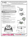
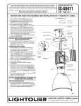
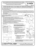
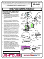
READ AND UNDERSTAND THESE INSTRUCTIONS BEFORE INSTALLING FIXTURE INSTRUCTION SHEET NO. This luminaire is intended for installation in accordance with the National Electrical Code and local regulations. To assure full compliance with local codes and regulations, check with your local electrical inspector before installation. To prevent electric shock, turn off electricity at fuse box before proceeding. IS:40421 Retain these instructions for maintenance reference. Page 1 of 2 C1101 INSTRUCTION SHEET FOR ASSEMBLY AND INSTALLATION OF 12 & 16” PENDALYTE SERIES WITH CORD AND CABLE OUTLET BOX Note: This instruction sheet covers several luminaire styles. Powerhead assembly, lamp type, and reflector system may vary slightly from that shown, but installation is the same. WIRE NUTS SUPPORT CABLE CROSSBAR STUD POWER HEAD ASSEMBLY: 1. 2. 3. 4. 5. 6. 7. Remove DOOR from POWERHEAD by loosening SCREW on top of MOUNTING PLATE (SCREW is located directly above PIN on POWERHEAD DOOR which protrudes through BOTTOM PLATE). Pull DOOR directly away from POWERHEAD (Fig. 1). Partially thread two SCREWS (provided with SUSPENSION KIT) into POWERHEAD MOUNTING PLATE Thread CABLE ADJUSTER into SUPPORT PLATE and fully tighten (Fig. 2). Place POWERCORD down through hole in SUPPORT PLATE. Note: The end of POWERCORD with fiberglass sleeving and tape on each conductor should be placed inside the POWERHEAD. Secure POWERCORD in place by wrapping SNAP-IN BUSHING around POWERCORD and pushing BUSHING down into hole in SUPPORT PLATE. Note: Allow at least six inches of POWERCORD inside POWERHEAD (Fig. 1). Loosen KNURLED RING on CABLE ADJUSTER. Pass SUPPORT CABLE down into opening in top of CABLE ADJUSTER. Note: SUPPORT CABLE end without CRIMP should be placed into CABLE ADJUSTER. Make certain ADJUSTING COLLAR has been placed up SUPPORT CABLE so CRIMP will go down into recessed portion of ADJUSTING COLLAR prior to passing SUPPORT CABLE into CABLE ADJUSTER (Fig. 1 & Fig. 2). Pass POWERCORD through hole in MOUNTING PLATE and align KEYSLOTS in SUPPORT PLATE with two SCREWS on top of MOUNTING PLATE. Turn SUPPORT PLATE counter-clockwise until SCREWS are in the small slot area of the KEYSLOT. Fully tighten SCREWS. (Fig. 1 & Fig. 2). Make wiring connections inside POWERHEAD using WIRE NUTS (local hardware item). Compact fluorescent and incandescent luminaires: Black luminaire lead to hot (black) POWERCORD lead; White luminaire lead to neutral (white) POWERCORD lead. Attach bare copper ground wire attached to BOTTOM PLATE to green ground wire from POWER CORD and BALLAST (if supplied). For metal halide luminaires, refer to wiring diagram in Fig. 4. CANOPY CABLE ADJUSTER ADJUSTING COLLAR POWERCORD SNAP-IN BUSHING CRIMP 2. 3. 4. 5. 6. 7. Determine approximate overall height of luminaire. If necessary cut excess POWERCORD. Note: Add a minimum of six inches to overall length determined for wiring into OUTLET BOX. If POWERCORD has been shortened; strip outside insulation back a minimum of six inches. Strip insulation on each conductor by approximately 3/8”. Adjust the overall length of SUPPORT CABLE to approximately the same length as POWERCORD by pushing excess CABLE down into CABLE ADJUSTER. Caution: make certain CABLE does not interfere with internal wiring and components (Fig. 1 & Fig. 2). Pass POWERCORD through hole in CANOPY (Fig. 1). Partially thread STUD into CROSSBAR. Using appropriate slots in CROSSBAR, secure CROSSBAR to OULTLET BOX using OUTLET BOX SCREWS (provided with OUTLET BOX). While supporting CANOPY ASSEMBLY make connections: black POWERCORD lead to hot supply lead; white POWERCORD lead to neutral (white) supply lead Green POWERCORD lead is a ground wire and must be connected to grounding terminal or ground lead inside OUTLET BOX. Use WIRE NUTS (local hardware item). Push supply wires and connections back into OUTLET BOX. Place CANOPY over STUD and thread ADJUSTING COLLAR onto STUD until CANOPY is fully secure against ceiling. SNAP-IN BUSHING POWERCORD SNAP-IN BUSHING SUPPORT PLATE APPROX. 6” MOUNTING PLATE KEYSLOT FIG. 2 SCREW POWER HEAD DOOR PIN NECK COLLAR BOTTOM PLATE COLLAR PIN COLLAR HALOGEN LAMP CANOPY INSTALLATION AND HEIGHT ADJUSTMENTS: 1. KNURLED RING OUTLET BOX SCREW (AUXILIARY OPTION ONLY) LIP FIG. 3 LENS REFLECTOR/ REFRACTOR RING FIG. 1 277V 240V 208V 120V COMMON BLACK WHITE CONNECT TO APPROPRIATE VOLTAGE POWER CORD GROUND GROUND METAL HALIDE BALLAST CAUTION: MAKE CERTAIN WIRES ARE NOT PINCHED BETWEEN PARTS. FIG. 4 A COMPANY 631 Airport Road, Fall River, MA 02720 INSTRUCTION SHEET NO. READ AND UNDERSTAND THESE INSTRUCTIONS BEFORE INSTALLING FIXTURE IS:40421 This luminaire is intended for installation in accordance with the National Electrical Code and local regulations. To assure full compliance with local codes and regulations, check with your local electrical inspector before installation. To prevent electric shock, turn off electricity at fuse box before proceeding. C1101 Retain these instructions for maintenance reference. Page 2 of 2 FINAL HEIGHT ADJUSTMENT AND INSTALLATION: 1. 2. 3. 4. 5. Adjust luminaire to final height: To raise POWERHEAD push down on KNURLED RING on CABLE ADJUSTER and push SUPPORT CABLE into CABLE ADJUSTER. To lower POWERHEAD, push down on KNURLED RING on CABLE ADJUSTER and allow SUPPORT CABLE to come out of CABLE ADJUSTER. Fully tighten KNURLED RING on CABLE ADJUSTER. Push any excess POWERCORD into hole in CANOPY, secure POWERCORD in place by wrapping SNAP-IN BUSHING around POWERCORD and push BUSHING into hole in CANOPY (Fig. 1). Reinstall DOOR and secure in place by tightening SCREW firmly onto MOUNTING PLATE (Fig. 1). Follow steps below for REFLECTOR/REFRACTOR installation. Install recommended lamp(s). Note: On metal halide luminaires with auxiliary lamp option, install halogen lamp as shown in Fig. 3. FOAM GASKET NECK CAUTION: MAXIMUM WATTAGE AS MARKED ON LUMINAIRE MUST NOT BE EXCEEDED. FIG. 4 TAB NOTCH SLOT REFLECTOR/REFRACTOR INSTALLATION: 1. 2. 3. 4. COLLAR Slide COLLAR up NECK. Peel off backing from FOAM GASKET and adhere to TABS on REFLECTOR PLATE (Fig. 4). Tip REFLECTOR/REFRACTOR over REFLECTOR PLATE and allow REFLECTOR/REFRACTOR to rest on FOAM GASKET. Secure REFLECTORREFRACTOR in position by aligning SLOT in COLLAR over PINS and slide COLLAR down NECK. Twist COLLAR counter-clockwise allowing PINS to rest in NOTCHES (Fig. 5). COLLAR PIN FIG. 5 12” REFRACTOR SUPPORT PLATE INSTALLATION: (Required for luminaires using 12” REFRACTORS only) 1. 2. Align SUPPPORT PLATE over SOCKET MOUNTING PLATE. Secure SUPPORT PLATE to SOCKET MOUNTING PLATE using two SCREWS provided with REFRACTOR (Fig. 7). LENS INSTALLATION (WHEN PROVIDED): 1. Place lens up into lip of REFLECTOR/REFRACTOR. Secure in place by expanding RING around outside lip of REFLECTOR/REFRACTOR allowing spring tension of RING to close around lip (Fig. 1). SOCKET MOUNTING PLATE CROSSBLADE LOUVER INSTALLATION (when provided): 1. 2. 3. Hook “J” shaped end of SUPPORT SPRING through the two holes in SOCKET MOUNTING PLATE as shown in Fig. 6. While carefully pulling down on SUPPORT SPRING hook “V” shaped end of SUPPORT SPRING through hole in CROSSBLADE LOUVER. Carefully allow SUPPORT SPRING to pull CROSSBLADE LOUVER up into REFLECTOR making certain TABS on CROSSBLADE LOUVER sits securely into recessed LIP of REFLECTOR (Fig. 6). SOCKET SUPPORT PLATE SOCKET MOUNTING PLATE SUPPORT PLATE SCREW SUPPORT SPRING REFRACTOR CROSSBLADE LOUVER TAB FIG. 7 FIG. 6 A COMPANY 631 Airport Road, Fall River, MA 02720