1
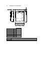
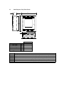
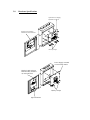
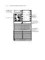
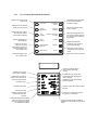
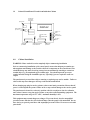
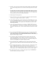
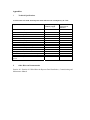
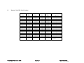
ZT 37 -250
PREMIER AL Local Panel
Repeater Application,
Installation and
Commissioning Manual
For the PREMIER AL
Contents
1.0 Introduction ........................................................................................................... 2
2.0 Cabinet Specifications ........................................................................................... 3
2.1 Repeater Panel Order Codes & Descriptions ..................................................... 3
2.2
Small Repeater Semi-Flush Bezel..................................................................... 4
2.3
Small Repeater Fully Flush Bezels ................................................................... 5
3.0 Hardware Specifications........................................................................................ 6
3.1 User Controls & Indications (General Overview).............................................. 7
3.2 Printed Circuit Board Viewed from Inside the Cabinet ........................................ 9
4.0 Cabinet Installation................................................................................................ 9
5.0 Display Address Setting ...................................................................................... 11
6.0 Commissioning Procedure................................................................................... 11
Appendices .................................................................................................................... 14
i Technical Specifications...................................................................................... 14
ii Other Relevant Documentation ........................................................................... 14
iii
Repeater Node DIL Switch Settings ................................................................ 15
1.0
Introduction
The A1575 Premier AL Repeater (REP AL) range of repeaters is designed for use with the Premier AL
Panel. Three versions are available for each panel: 1)
The Basic LCD display Repeater with user controls (Please refer to the section on user controls for
a full specification). It is powered from the panel and comes in a smaller cabinet size as shown in
the Cabinet Specifications.
2)
The repeater complete with power supply, in the smaller enclosure as above.
3)
The repeater complete with zone LEDs and space for optional printer. This unit is housed in the
larger cabinet detailed in the Cabinet Specifications.
The display with the data cable terminations is fitted to the removable door. The power supply option is
fitted to a detachable chassis, thus facilitating a completely empty enclosure for first fix installation. Top
entry plastic grommets, bottom/rear entry plastic grommets (for mains) and rear entry knockouts are
designed to assist with cable installation.
The repeater has a 4 line x 20 character backlit LCD display, showing device address, zone, type, status and
location text. The user controls are accessed by means of keyswitch enabled membrane controls.
Up to 14 repeater panels can be connected to the RS 485 repeater terminals. The basic repeater can be
powered either from the panel’s auxiliary supply (See Battery and Loop calculator for maximum values) or
from a local power supply.
Only One Repeater can be powered from the Premier AL Aux Power Rail. ( 28v 0v). Any additional
Repeater will need a separate power source, unless a power supply is fitted in the Unit.
2.0
Cabinet Specifications
The repeater panels are available with surface, semi flush or fully flush enclosures to match the PREMIER
AL panels. The section of this manual shows the two panel cabinet options.
c
b
a
Protection Plugs
a
b
c
2.1
Dimensions
13 off
370mm
325mm
106mm
Repeater Panel Order Codes & Descriptions
Part No
2500/830
2500/842
2500/844
Description
Premier AL LCD repeater panel powered from main panel. Size - 370h x 325w x 100d
Premier AL repeater c/w 1A psu). Size 370h x 325w x 100d
Premier AL LCD repeater with zone LEDs c/w 1A psu and space for printer.
Size – 480h x 410w x 140d
2.2
Small Repeater Semi-Flush Bezel
h
c
e
g
f
a
d
b
Hole height
Hole width
Hole depth
Max bezel height
Max bezel width
a
b
c
d
e
Dimensions
375mm
330mm
76mm
435mm
388mm
Bezel overlap
Bezel depth
Door protrusion
f
g
h
30mm
30mm
30mm
Part No
2501/121
2501/124
Description
Semi-flush bezel to fit A1575 Small Repeater
Semi-flush bezel to fit A1575 large Repeater
2.3
Small Repeater Fully Flush Bezels
e
c
a d
b
f
Hole height
Hole width
Hole depth
Bezel height
Bezel width
Hinge protrusion
Part No
2501/127
2501/128
2501/129
2501/153
2501/154
2501/155
a
b
c
d
e
f
Dimensions
375mm
345mm
106mm
411mm
423mm
20mm
Description
Fully-flush painted bezel for A1575 small repeater panel (painted to customer's specification)
Fully-flush stainless steel bezel for A1575 small repeater panel (brushed or polished)
Fully-flush brass bezel for A1575 small repeater panel (brushed or polished)
Fully-flush painted bezel for A1575 large repeater panel (painted to customer's specification)
Fully-flush stainless steel bezel for A1575 large repeater panel (brushed or polished)
Fully-flush brass bezel for A1575 large repeater panel (brushed or polished)
3.0
Hardware Specifications
Optional Power Supply
Mounted on Chassis
Display board assembly
mounted on removable door
Battery Clamps
Power Supply mounted
on removable chassis
Display board and zone
LED assembly mounted
on removable door
Battery Clamps
Optional Printer
3.1
User Controls & Indications (General Overview)
20 character by 4 line
LCD display. Back-lit
when event present or
Access controls switch
ON.
User indications
1
EVACUATE
OVERRIDE
DELAY
2
SCROLL
MESSAGES
SILENCE
BUZZER
3
TEST
ALARMS
SILENCE / RESOUND
ALARMS
4
TEST
DISPLAY
RESET
5
ACCESS MENU
MENU UP
6
MENU DOWN
User controls. Only
override delay is
available without
operating the access
controls keyswitch
ESCAPE
FAULT
ENTER
Switch to 1 to enable
controls (enter level 2).
Override delay operates
with switch in either
position.
ACCESS
CONTROLS
1
2
3
4
5
6
7
8
9
10
11
12
13
14
15
16
17
18
19
20
21
22
23
24
25
26
27
28
29
30
31
32
ZONAL FIRE AND FAULT INDICATION
Zonal fire (red) and fault
(yellow) indications.
Pulse to indicate a nonsilenced event,
continuous to indicate an
event has been silenced
3.1.1
User Controls and Indications in Detail
Operates all sounder circuits
continuously
1
EVACUATE
OVERRIDE
DELAY
2
SCROLL
MESSAGES
SILENCE
BUZZER
Activates all alarm outputs
when pressed. Alarms
silenced when released
3
TEST
ALARMS
SILENCE / RESOUND
ALARMS
Tests all indications and
internal buzzer
4
TEST
DISPLAY
RESET
Displays the next message
at the current event level
Enters the user menu
system for access to
further level 2 and level 3.
Increments digits in user
menu number entry
5
6
ACCESS MENU
MENU UP
MENU DOWN
ESCAPE
ENTER
Overrides the delay to outputs
function and immediately
actions the outputs
Silences the internal buzzer
for any condition
Silences sounding devices for
fire events. If already silenced
the previous alarm condition is
re-activated
Resets all fire and fault
indications. (Fire conditions
must be silenced first)
Used within access menu to
delete items and escape from
menus
Enters text in the access menus
Decrements digits in user
menu number entry
Constant to indicate delay is
active, pulsing when delay
running
Indicates power supply
active (mains or battery)
Indicates Discovery device drift
compensation limit reached. [Not
used on Xplorer]
Indicates some part of the system
has been disabled
Pulses when a new fire is
active, continuous when all
fires have been silenced
Pre-alarm active
Indicates internal fault
Continuous when the buzzer has been
silenced
FAULT
Pulses if new fault
detected, continuous if all
active faults have been
silenced
Pulses if fault detected with either
alarm circuit or any loop alarm
controller. Continuous for alarm
circuit disabled conditions
Continuous to indicate some part of
the system is in test mode
Pulses to indicate another message is
available for viewing with the scroll events
button
3.2
Printed Circuit Board Viewed from Inside the Cabinet
EPROM WITH
SOFTWARE
REFERENCE
PROC RESET
DISPLAY
NODE ADDRESS
DIL SWITCH
PROC FAILED
COMMS FAILED
PRINTER
INTERFACE
4.0
ZONE BOARD DISABLE
MONITORING LINK
B/+
A/SCN
B/+
A/SCN
FLT
24V
0V
CONNECT TO
PANEL
CONNECT TO
NEXT REPEATER
24V AND 0V
SUPPLY
ZONE BOARD
INTERFACE
Cabinet Installation
WARNING: Please read this section completely before commencing installation.
Prior to commencing installation of the control panel, ensure that adequate precautions are
taken against static damage to the sensitive electronic components on the control board. You
should discharge any static electricity you may have accumulated by touching a convenient
earthed object, e.g. an unpainted copper radiator pipe. You should repeat the process at
regular intervals during the installation process, especially if you are required to walk over
carpets.
The panel must be powered down before removing or replacing any card or module. Failure to
observe this may cause damage to the loop cards and the motherboard.
When changing any plug-in cards or printers, observe anti-static precautions. Ensure that all
power is removed from the system. Failure to do so may result in damage to the cards or panel.
The panel must be located in a clean, dry position which is not subject to shock or vibration
and at least 2 metres away from pager systems or any other radio transmitting equipment. The
maximum temperature range is 0ºC - 40ºC; maximum humidity is 95%.
This equipment may contain dangerous voltages. To prevent electric shock to unqualified
personnel ensure that the door is locked at all times when the panel is left unattended. Do not
leave the key to open the panel door with unqualified personnel. There are no user-serviceable
parts inside.
IMPORTANT NOTES ON BATTERIES:
DANGER: Batteries are electrically live at all times, take great care never to short circuit the
battery terminals.
WARNING: Batteries are often heavy, take great care when lifting and transporting batteries.
For weights above 24 kilos, lifting aids should be used.
WARNING: Do not attempt to remove battery lid or tamper with the battery internal workings.
Electrolyte is a highly corrosive substance, and presents significant danger to yourself and to
anything else it touches. In case of accidental skin or eye contact, flush the affected area with
plenty of clean, fresh water and seek immediate medical attention.
VRLA batteries are “low maintenance” requiring no electrolyte top-up or measurement of
specific gravity.
WARNING: If required, clean the case with a cloth that has been soaked or dampened with
distilled water. Do not use organic solvents (such as petrol, paint thinner, benzene or mineral
spirits) and other materials can substantially weaken the case.
WARNING: Avoid operating temperatures outside the range of -15°C/5°F to +50°C/122°F for
float/standby applications.
DANGER: Do not incinerate batteries. If placed in a fire, the batteries may rupture, with the
potential to release hazardous gases and electrolyte. VRLA batteries contain substances
harmful to the environment. Exhausted batteries must be recycled. Return them to the battery
manufacturer or take them to your Council tip for appropriate disposal.
The versions of this repeater panel fitted with a power supply requires a 230V AC supply. All
installation work should be carried out in accordance with the recommendations of BS5839
Part 1 and the current edition of the IEE regulations by suitably qualified and trained
personnel.
The panel must be earthed.
Locate the panel keys and the Installation Kit containing installation spares as follows:
1 set of battery leads (positive, negative and a jumper lead)
3k9 resistors
1A spare fuse for 24V Aux Supply
1.5A spare battery fuse
Open the display door with the key provided. Carefully remove the repeater panel interior by
releasing the cables to the display (where fitted) and unscrewing the door pin located in the
bottom fold of the door. On the repeater panel version fitted with a power supply, remove the top
two chassis screws (located top left and right and removing the lower two screws (located bottom
left and right) on the chassis plate.
NOTE: The chassis screws are bright chrome finish.
Fix the empty enclosure to the wall using the fixing hole(s) in the upper section of the enclosure.
Complete the fixing operation using the remaining fixing holes in the enclosure.
Gland installation wiring into the enclosure using the cable entry points provided. Leave plugs in
any unused cable entry holes.
Replace and fix the repeater panel door and chassis. Reconnect any internal earth wires.
5.0
Display Address Setting
Each repeater is given an individual address to enable the main panel to monitor its presence on
the system. It is necessary to set the repeater address number at each repeater panel by means of
the node address DIL switch and also to set the number of displays on the main panel via the
engineers set up menu (Please refer to the relevant panel manual to set the number of displays).
The table in Appendix iii shows the setting options for the node address DIL switch.
6.0
Commissioning Procedure
1. If a power supply unit is fitted then gland a 230 VAC mains supply into the enclosure
and attach the cables to the mains terminal block. DO NOT SWITCH THE MAINS
POWER ON AT THIS TIME.
2. Set the node address DIL switch on the A1575 board to the required display number
as shown in Appendix iii. Each repeater must be addressed sequentially without gaps
in the numbering system.
3. Connect the cables from the B/+ and A/- terminals on the main fire alarm panel to the
B/+ and A/- terminals respectively on the A1575 board. Connect the data screens to
the SCN terminal adjacent to the A/- terminal.
4. Connect the d.c. power supply cables to the 0V and 24V terminals on the A1575
board. The d.c. supply may be provided by the main fire alarm panel or by a local
power supply unit if fitted.
NOTE: If the D.C. supply is derived from the main fire alarm panel then ensure
that the panel is switched off before connecting any cables.
5. If a local power supply unit is fitted then check that the FLT terminal on the power
supply unit is connected to the FLT terminal on the A1575 board.
6. If the D.C. power is derived from the main fire alarm panel then ensure that the drain
wires of the incoming cables have been connected to an Earth point at the fire alarm
panel.
7. If a printer and/or zone board is fitted then check that the ribbon cables are correctly
connected. If the zone board is fitted then ensure that the link at LK1 on the back of
the A1575 board is removed. If this link is fitted then the zone A1575 display board
will not monitor the zone board for ribbon disconnection.
8. Switch the main fire alarm panel on.
9. If the A1575 derives its power from a local power supply then connect the batteries
to the local power supply unit and switch the a.c. mains on.
10. At the main fire alarm panel access the engineer menu with the highest access code
and select NUMBER OF DISPLAYS as described in the panel’s installation manual.
Set the number of displays to the required value. When this has been done exit the
menu mode completely.
11. At the A1575 repeater the display may be showing a COMMS FAILED indication.
Press CLEAR DISPLAY on the repeater. The display should clear and show only the
time and fire alarm panel name. The same should be displayed at the main fire alarm
panel.
12. Press and hold the TEST DISPLAY button on the repeater. Check that all the LEDs
on the repeater illuminate, the LCD backlight illuminates, the LCD shows all the
pixels as black, the buzzer sounds and the zonal LEDs illuminate if fitted. Release the
button to return the display to normal.
13. If a local power supply is fitted then disconnect the negative battery lead at the
repeater and check that the repeater displays a local power supply fault. Press the
SILENCE BUZZER button to silence the fault buzzer. Re-connect the battery lead
and press CLEAR DISPLAY to return the display to normal.
14. Press and hold the TEST ALARMS button on the repeater and check that all the
alarm circuits operate. Release the button and check that all the alarm circuits switch
off.
15. Remove the data cable from the A/- terminal on the repeater. Check that the repeater
shows a COMMS FAILED indication and the main fire alarm panel shows a
DISPLAY OFF-LINE message (the display number will depend on the switch setting
of the repeater). Note: The fault indications could take up to 60 seconds to appear.
16. Re-connect the cable to the A/- terminal on the repeater. Press CLEAR DISPLAY
and check that the system returns to normal.
If you are installing more than one A1575 repeater then each repeater should be installed
and commissioned individually.
Appendices
i
Technical Specifications
A1575 Premier AL Stand Alone Repeater mains failed current consumption @ 25 V DC.
Repeater status
Mains failed battery current
40mA
Powered from
local 1A p.s.u.
batteries
105mA
Alarm condition battery current
Maximum battery current
75mA
80mA
140mA
145mA
40mA
80mA
180mA
105mA
145mA
245mA
45mA
80mA
420mA
110mA
145mA
485mA
45mA
85mA
560mA
110mA
150mA
625mA
With zone board
Mains failed battery current with zone board
Alarm condition battery current with one board
Maximum battery current with zone board
With printer
Mains failed battery current with printer
Alarm condition battery current with one board
Maximum battery current with printer
With printer and zone board
Mains failed battery with zone board and printer
Alarm condition battery current with one board
Maximum battery current with zone board and
printer
ii
Powered from panel
auxiliary supply
Other Relevant Documentation
Premier AL / Premier AL Global Network Repeater Panel Installation , Commissioning and
Maintenance Manual.
iii
Repeater Node DIL Switch Settings
Decimal
Value
0
1
2
3
4
5
6
7
8
9
10
11
12
13
14
15
Document Ref: A1575ins.doc / Rev 1 19/9/01
S13 – 1
Bit 0
OFF
ON
OFF
ON
OFF
ON
OFF
ON
OFF
ON
OFF
ON
OFF
ON
OFF
ON
S13 – 2
Bit 1
OFF
OFF
ON
ON
OFF
OFF
ON
ON
OFF
OFF
ON
ON
OFF
OFF
ON
ON
Page 15 of 15
S13 – 3
Bit 2
OFF
OFF
OFF
OFF
ON
ON
ON
ON
OFF
OFF
OFF
OFF
ON
ON
ON
ON
S13 – 4
Bit 3
OFF
OFF
OFF
OFF
OFF
OFF
OFF
OFF
ON
ON
ON
ON
ON
ON
ON
ON
PREMIER AL
Assignment
Not used
Repeater 1
Repeater 2
Repeater 3
Repeater 4
Repeater 5
Repeater 6
Repeater 7
Repeater 8
Repeater 9
Repeater 10
Repeater 11
Repeater 12
Repeater 13
Repeater 14
Not used for
Repeaters
Originator JBJ Checked by ___