1
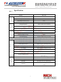
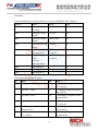
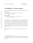
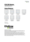
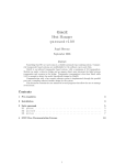
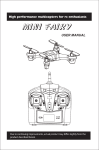
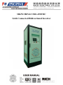
30KW/380VAC/300~450VDC
Grid-Connected Bidirectional Inverter
Content
Specification ............................................................................... 3
Front Panel.................................................................................. 4
HMI Display ............................................................................. 10
Communication Protocol .......................................................... 14
Trouble Shooting ...................................................................... 19
2
一、 Specification
Supply
Characteristics
Control
Input Power
Rating
MODEL
SDC-30K
Rated Output Capacity KW
30KWA
Rated Output Current (DC) A
80A
Rated Input Current (AC) A
85A
Rated Output Voltage
300-450VDC
Voltage/Frequency
380V to 460 VAC at 50/60 Hz
Allowable Voltage Fluctuation
+10% to -15%
Allowable Frequency Fluctuation
±3Hz/300ms
Control Method
Sine wave PWM method
Input Power Factor
0.95 or more
Output Voltage Accuracy
±10%
Overload Capacity
150% of rated current per minute
Protective Function
Constant Setting
Using the digital operator
Instantaneous Overcurrent
Stops at approx. 200% of the input current
Overload
Stops after 1 minute at 150% of rated current
Undervoltage (Output)
Stops at approx. 200 VDC or less
Undervoltage (input)
Stops at approx. 300 VAC or less
Overvoltage
Stops at approx. 500VAC or less
Fin Overheat
Protected by thermistor
Ground Fault
Protected by electronic circult
Stops at fluctuation of more than ±3 Hz of rated
Conditions
Environmental
Power Frequency Error
input frequency
Location
Indoors(Protected from corrosive gases and dust)
Ambient Temperature
-10℃ to +55℃
Humidity
90% RH or less (no condensation)
2
9.8m/s at less then 20 Hz, up to1.96m/s2 at 20 Hz
Vibration
to 50Hz
3
Front Panel
Human-Machine Interface
Card Reader
Emergency Stop
Start
(Red)
Stop
(Green)
4
Interior Layout-Upper Part
(α)
Main Power
Breaker
3-Phase AC
Power Meter
(β)
3-Phase 380V
Input Power
Terminal
DC voltage/
current detector
(γ)
Battery Terminal
5
Interior Layout-Lower Part
Bidirectional
Inverter
(30KW)
3-Phase Transformer
380V/190V 50KWA
Reactor Choke
6
Rear Panel-Upper Part
DC Fuse
3-Phase
AC Fuse
Fuses
External
Communication
port
(δ) Control
Power Breaker
7
Rear Panel-Lower Part
8
Side
External Fault Signal Input
Terminal Description:
1.
2.
3.
D and A should be closed for the inverter operation
E and A are short circuit when external fault is input
F and G are for Inverter ready signal (dry contact)
9
Human-Machine Interface
Display 1
(B)
(B) Change to discharging
(A)
(A)In the charging
mode
(C) Voltage
(F) Discharge
(F)
(C)
Current
Voltage/Current Settings
(G) Temp. Indication
(G)
(D)(D)
Status
Indicator
(H) Page Change
(H)
(E)Current,
(E) Voltage,
(I)
(I) Card Log-in Indicator
Power monitor
(
)
(J) Error Message Display
Operation Steps:
1.
Connect the DC terminals:Pay attention to the correct connection and fault
messages display.
2.
Switch on the main power breaker.
3.
Switch on the control power breaker.
4.
Choose (A) or (B) for Charging or Discharging mode.
5.
Set (C) or (F) Voltage/Current. In the charging mode, press (A) first and then set
(C)
6.
In the discharging mode, press (B) and then set (F)
7.
Complete the settings (Display 2)
8.
Card Reader for log-in
9.
Press the Start key
10
Display 2
Back to Menu
Charging Mode Setting
Discharging Mode Setting
After setting all the conditions on 1st display, it goes to the 2nd display.
In charging mode, the operation steps
1. Timer Function
z
z
z
Press (N) to enable the timer function.
Set the timer in the unit of minute in (K).
In the charging mode, the time set in (K) limits the time and when it is finished,
the “complete" on the right side shows.
2. CV Function
When battery voltage is ≧ setting voltage-(L)Delta and continues for (Q)
minutes,the completed status will be displayed when it is finished.
3. The minimum current
When the battery current is ≦(M)Ilim and continues for (R) minutes,the
completed status will be displayed when it is finished.
The operation in the discharging mode is the same as in the charging mode
11
Display 3
AC Power Monitor
(
)
(
)
(
)
(V)
Press AC Power on the Menu page to go to this page
(S) The voltage, current, balanced voltage and current in each phase out of the three
phase AC power
(T) Efficiency, power, apparent power, power factor, frequency Hz
(U) Battery voltage, current and status indicator
(V) Transformer and choke temperature
12
Display 4
Card Number Setting
Card 1-5
Card 6-10
Back to Main Menu
User
Press “Card setting” on the menu page, and then enter the password.
Introduction:
Using this setting to control the personnel of operating the machine; please use
the new card to swipe the card machine, then the user password will display on W, if
the password has stored in Y (the maximum 10 sets), then the X light will be light in
green. If not, then please set the user code (W) into card 1~10 column.
13
Protocol
Protocol 9600 baud, No parity, 8bits data, 1stop bit, MODBOS RTU, Address=1
Address
Name
Range
W/R
6010
Charging Voltage
Setting
300V~450V
W
6011
Charging Current
Setting
1~100%
W
6012
Discharge Voltage
Setting
300V~450V
W
6013
Discharge Current
Setting
1~100%
W
6014
5555H START
AAAAH STOP
5555H
AAAAH
W
6015
5555H Charging
Mode
AAAAH
Discharge Mode
5555H
AAAAH
W
6016
State Register
6017
State Register 1
6018
State Register 2
R
6016 Operating State Register
bit
State
bit
State
0
0:Charge 1:Discharge
8
1: Charging completed within
CV capacity
1
0:STOP 1:RUN
9
1: Charging completed within I
lim capacity
2
0:Normal 1:Error
10
1: Discharge completed within
stipulated time
3
0:Not Ready
11
1: Discharge completed within
CV capacity
4
1: Charging completed within
stipulated time
12
1: Discharge completed within
I lim capacity
5
1: Charging completed within
CV capacity
13
1: Discharge completed within
stipulated time
1:Ready
14
6
1: Charging completed within I
lim capacity
14
1: Discharge completed within
CV capacity
7
1: Charging completed within
stipulated time
15
1: Discharge completed within
I lim capacity
15
6017 Operating State Register 1
bit
State
bit
State
0
FU: fuse on the converter burnt out
8
OH: Over Heat
1
UV1:Main Circuit Under Voltage
9
OH1: Over Heat1
2
UV2:Control Power Under Voltage
10
OL1: Over Load1
3
UV3:MC Trip
11
OL2: Over Load2
4
SC: Short Circuit
12
OL3: Over Load3
5
GF: Ground Fault
13
OL4: Over Load4
6
OC: Over Current
14
7
OV: Over Voltage
15
Reserve
Reserve
6018 Operating State Register 2
bit
State
bit
State
0
Emergency STOP button
16
DC fuse burnt out
1
Reserve
Reserve
Reserve
Reserve
17
AC fuse burnt out
18
Charging Trip
19
SD low voltage
20
Low voltage or battery not
ready
Reserve
Reserve
Reserve
Reserve
21
22
Door improperly closed
Reactance overheat >90℃
23
Transformer overheat >90℃
24
Unmatched Transformer or
battery
25
13
Reserve
Reserve
Reserve
Reserve
Reserve
14
Converter EEPROM ERROR
30
15
Reserve
31
Reserve
Reserve
Reserve
Reserve
Reserve
Reserve
Reserve
2
3
4
5
6
7
8
9
10
11
12
26
27
28
29
16
Address Name
Format
Unit
Write (W) /
Read (R)
7605
R phase voltage
###.#
V
R
7609
R phase current
###.#
A
R
7606
S phase voltage
###.#
V
R
7610
S phase current
###.#
A
R
7607
T phase voltage
###.#
V
R
7611
T phase current
###.#
A
R
7608
Average voltage
###.#
V
R
7612
Average current
###.#
A
R
7617
Active Power
-###.#
KW
R
7621
Reactive Power
-###.#
KVar
R
7625
Apparent Power
-###.#
KVA
R
7629
Power Factor
-#.###
PF
R
7600
Frequency
##.##
Hz
R
Address Name
Format
Unit
Write (W) /
Read (R)
6070
Charging Voltage
setting
###
V
R
6071
SOC setting
###
%
R
6072
Current charging
Voltage
###.##
V
R
6073
Current charging
Current
-###.#
A
R
6074
Current Battery
Power
-###.#
KW
R
6075
Current Temperature
of transformer
-###.#
℃
R
6076
Current Temperature
of reactor
-###.#
℃
R
6077
Discharge Voltage
setting
###
V
R
17
6078
Discharge current
setting
###
%
R
※Those setting value above are decimal, the hexadecimal will shows "H" at the end
of the digital, and the "-"on format column means signed number.
18
Trouble Shooting
When AC Capacitor R-phase fuse burnt out, the NFB1 will OFF.
When AC Capacitor S-phase fuse 2 burnt out, the NFB2 will OFF.
When AC Capacitor T-phase fuse 3 burnt out, the NFB3 will OFF.
R-phase fuse 4 burnt out, the NFB4 will OFF
S-phase fuse 5 burnt out, the NFB5 will OFF
T-phase fuse 6 burnt out, the NFB6 will OFF
AC fuse burnt out, the NFB7 will OFF
Please check the cause then change the fuse.
Marquee message:
OH: heat sink of transformer overheated, please check the unit or fan of transformer.
SC: DC or AC shorted
GF: DC grounded error
OC: DC over current, please check the output current
OV: Battery or DC voltage over 500V
Transformer or battery unmatched: battery is not connected when operating or the
voltage of transformer cannot reach to 250VDC in 60 seconds.
19