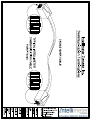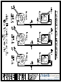
1
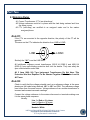
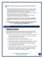
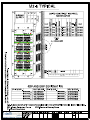
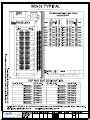
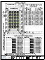
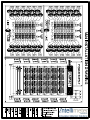
[email protected] intellimeter.on.ca M3 8-16-24 Centres – Installation & Operation Manual – Copyright © 2013 1125 Squires Beach Road, Pickering, Ontario L1W 3T9 Phone: 905-839-9199 Fax: 905-839-9198 Revision 5.0 2013-06-24 INDEX Part One .................................................................................................................................... 3 1. Measurement Canada Requirements .............................................................................. 3 Part Two .................................................................................................................................... 4 2. Metering Rules ................................................................................................................ 4 Part Three .................................................................................................................................. 5 3. Installation Instructions .................................................................................................... 5 Part Four .................................................................................................................................... 6 4. Service Types.................................................................................................................. 6 Part Five .................................................................................................................................... 7 5. CT Wiring and Lengths .................................................................................................... 7 Part Six ...................................................................................................................................... 8 6. M3 - Meter Field Installation, Testing, and Troubleshooting Procedure ........................... 8 Part Seven ................................................................................................................................. 8 7. LED Indicators ................................................................................................................. 8 Part Eight ..................................................................................................................................10 8. Communication Cable ....................................................................................................10 Part Nine ...................................................................................................................................11 9. Pre Site Visit Check List .................................................................................................11 Appendix ...................................................................................................................................11 Communication Terminations ................................................................................................12 Wiring for X00:5 AMP CTs .....................................................................................................13 Typical Layout M3-8 Panels Configuration .............................................................................15 Typical Layout M3-16 Panels Configuration ...........................................................................16 Typical Layout M3-24 Panels Configuration ...........................................................................17 M24 Installation Drawing ........................................................................................................18 INSTALLATION INSTRUCTIONS FOR M3 8-16-24 Centres Copyright © 2013 Intellimeter Canada Inc. 2 of 18 || Revision 5.0 2013-06-24 Part One 1. Measurement Canada Requirements Measurement Canada Notice to all Electrical Contractors and Owners (Applies to milli-Amp type CT’s only) This is to inform the electrical contractors who are installing any static type metering system that Current Transformers (CT’s) are assigned to a specific meter and are required to stay with that meter. Any CT’s that are not installed on the meter assigned and sealed with will void the meters seal and be considered a non-legal billing meter. On the side of the CT’s, the serial number of the meter and the potential line is indicated as a guide for the contractor. FOLLOW THE INSTALLATION DRAWINGS! Match the CT’s with the meter, and install them on the correct line to the correct phase. If there are any differences with the drawings compared to your distribution panel, CALL US IMMEDIATELY! CAUTION Phasing and CT installation are very important. If the metering system is not installed according to the installation drawings, the system will not work and any cost in correcting the installation by Intellimeter will be charged back to the installer / developer. INSTALLATION INSTRUCTIONS FOR M3 8-16-24 Centres Copyright © 2013 Intellimeter Canada Inc. 3 of 18 || Revision 5.0 2013-06-24 Part Two 2. Metering Rules #1. Current Transformers (CT’s) are directional. #2. Voltage references must be in phase with the load being metered and from the same source. #3. CT’s (milli-Amp) are certified to an assigned meter and to the meters assigned phase. Rule #1: If the CT’s are mounted in the opposite direction, the polarity of the CT will be opposite. The arrow on the CT’s indicates the direction from LINE to LOAD. HI LINE LOAD Similarly the “H1” is on the LINE SIDE. All Intellimeter milliamp current transformers (200:0.1A (2000:1) and 400:0.1A (4000:1)) have self-shorting protection built into the device. They can safely be open circuited while under load. All 5 Amp (X00: 5A) Type Instrument Transformers Do Not Have This Protection And Are Required To Be Shorted Together While Under Load At All Times. Rule #2: Check to verify that the voltage potential used, as a reference voltage, is the same phasing as the loads being metered. ABC is ABC not CBA. The reference voltage must come from the same source. Voltage reference from another transformer is incorrect and causes inaccurate readings. Connect the voltage reference to the meters disconnect or terminals making sure it is the same phase sequence. Usually: Line 1 = Red or ‘A’ phase Line 2 = Black or ‘B’ phase Line 3 = Blue or ‘C’ phase Neutral = White INSTALLATION INSTRUCTIONS FOR M3 8-16-24 Centres Copyright © 2013 Intellimeter Canada Inc. 4 of 18 || Revision 5.0 2013-06-24 Rule #3: (Intellimeter milliamp current transformers 200:0.1A and 400:0.1A only) When the metering system was tested at the factory, the CT’s were assigned to a meter and to a specific element of that meter. Under Measurement Canada regulation for electronic static sub-metering, the CT’s must be installed and used only with the meter and element that it was certified with. We have identified each CT so it can be easily installed following the installation drawing that was designed for that particular distribution. Follow the Installation Drawing! If there is a discrepancy with the drawing in comparison to your distribution panel, call us for assistance. For all 5Amp type Instrument Transformers, make sure you identify the phase that it was installed on for proper connection at the meter terminal block. PLEASE CALL IF ANYTHING IS NOT CLEAR. IT IS DIFFICULT TO CORRECT ERRORS ONCE INSTALLATION HAS BEEN COMPLETED! Technical Assistance: 905-839-9199 Part Three 3. Installation Instructions These installation instructions are generic for both types of multi-customer submetering systems. Again, call before you install if you require additional information on this process. If any of these steps are incorrect, call for assistance. 1. Confirm the drawings that were sent with the metering system are accurate. Verify the type of panel and that the distribution is the same. It is important that all assigned breaker phasing is correct. 2. Assign the proper panel to the identified distribution. 3. Verify the number of loads is the same as the number of meters. 4. Verify the type of system is the same as the meters supplied, (Ex. 120/208V, 100A or 200A, 3 phase 4 wire, single phase 3 wire network system, etc). 5. Mount the panel as indicated by the drawing. Call to inquire if a different mounting configuration would work better. 6. Refer to the drawings to sort out the CT’s to be installed on the load feeders. 7. One feeder at a time, install the CT’s so the arrow is pointing towards the load. Confirm on the drawing, the installed CT corresponds to the correct phase of the suite. Continue until all CT’s are installed. INSTALLATION INSTRUCTIONS FOR M3 8-16-24 Centres Copyright © 2013 Intellimeter Canada Inc. 5 of 18 || Revision 5.0 2013-06-24 8. Supply a voltage reference from the distribution panel. Depending on the configuration, minimum is a 15A breaker and the number of phases should match what is required on the drawing. 9. If the system is automated, a CAT 5, 4 pair #24 (Network cable) is required to be pulled from one metering panel to the next until it reaches the communication cabinet that is usually mounted in the communication room or main electrical room. Refer to single line drawing. 10. Attached is a checklist that is to be completed, verified and faxed back to Intellimeter before commissioning is scheduled. NOTE: The electrical contractor will provide an electrician for the duration of the commissioning for inspection and for any modification re-work required. Intellimeter is not liable to work on the electrical distribution and will only be terminating the communication lines. All deficiencies will be recorded and sent to the electrical contractor for correction before returning to site. Part Four 4. Service Types ***** Single Phase (120/240) Line 1 = CT1 Line 2 = CT2 Network Two Phase Three Wire (120/208) - (3 sets) Typical Colour Code Line 1 = CT1 = A phase = Red Line 2 = CT2 = B phase = Black & Line 1 = CT1 = C phase = Blue Line 2 = CT2 = A phase = Red & Line 1 = CT1 = B phase = Black Line 2 = CT2 = C phase = Blue If the load is on B & C phase, Line 1 (CT1) is on B phase and Line 2 (CT2) is on C phase. This staggering of phasing is to match the typical three-phase four-wire distribution panel for 2 phase loads. Three Phase Meter Typical (120/208, 277/480, 347/600) Colour Code Line 1 = CT1 = A phase = Red / Orange Line 2 = CT2 = B phase = Black / Brown Line 3 = CT3 = C phase = Blue / Yellow INSTALLATION INSTRUCTIONS FOR M3 8-16-24 Centres Copyright © 2013 Intellimeter Canada Inc. 6 of 18 || Revision 5.0 2013-06-24 Part Five 5. CT Wiring and Lengths Current Transformers (CT’s) are directional ( “H1” also indicates Line Side. ). An arrow points to the load. HI LINE LOAD Typical: Install CT1 on Line 1 (Red), CT2 on Line2 (Black), and CT3 on Line3 (Blue). Refer to “Service Types” above for your system. External Current Transformers (CT’s) Twisted Pair #18-14 stranded colour code Intellimeter CT’s White (+) #1 200A (ICI30CT21) Black (-) Intellimeter CT’s Yellow / Black trace (+) #2 400A (ICI30CT41) Yellow (-) Instrument Transformers (CT’s) White (+) = X1 #3 (All X00: 5A Type) Black (-) = X2 The maximum length the CT leads can be extended is 400 feet for #1 & #2 and 50 feet only for #3. 1 twisted pair wire only for each CT. Intellimeter CT’s: <50ft = #18 minimum >50 to <150ft = #16 minimum >150 to 250ft = #14 minimum >250 to 400ft = #12 minimum Instrument CT’s: #14 minimum Identify the polarity and the phase the CT is installed on for proper termination. Always identify all wires. Refer to installation drawings and terminal labels for polarity and connection. INSTALLATION INSTRUCTIONS FOR M3 8-16-24 Centres Copyright © 2013 Intellimeter Canada Inc. 7 of 18 || Revision 5.0 2013-06-24 Part Six 6. M3 - Meter Field Installation, Testing, and Troubleshooting Procedure The M3 Centre is a solid-state multi-customer metering system that comes in three configurations: M3-8, M3-16 & M3-24. The M3-8 model has the metering capability of up-to 8 meters and one PT2000 twin unit pulse recorders with 8 spare input zones. The M3-16 model has the metering capability of up-to 16 meters and one PT2000 twin unit pulse recorders with no spare zones. The M3-24 has the metering capability of up to 24 meters and two PT2000 twin unit pulse recorders with 8 spare input zones. These models are modular and can be interconnected along with the TX2005 meters to meter any number of loads, any one location. Each individual customer has its register mounted to the meter circuit board: Quad has four electro mechanical registers and the twin has two electromechanical registers. Each individual meter has two LEDs and a form “A” pulse output mapped to a given pin location for recording metered data. Installation: Refer to above. Part Seven 7. LED Indicators: Dir1 Load1 ORG / RED Dir3 Load3 Dir4 Load4 Dir2 Load2 PWR ORG / RED ORG / RED ORG / RED / GRN Dir1 Load1 Dir2 Load2 PWR (Continued on next page) INSTALLATION INSTRUCTIONS FOR M3 8-16-24 Centres Copyright © 2013 Intellimeter Canada Inc. 8 of 18 || Revision 5.0 2013-06-24 Dir LEDs: When OFF, it indicates CT is installed correctly. When ON (Orange), CT is installed backwards, majority of load is in the negative direction, or phasing is incorrect. Re-verify the installation LOAD LEDs: Under load, this LED (Red) will pulse. The more load, the faster the pulsing. Refer to attach label for pulse rate (Ks). PWR: This LED (Green) indicates power is ON. Accuracy test: (Referring to the LOAD LED pulse) The M3 Centre Meter has a LOAD LED (Red) that will allow the meter to register a pulse at attached label for pulse rate (Ks). This will enable you to determine the accuracy of the meter with a radian standard or to mathematically determine the time between pulses for a given load. Voltage=Phase to Neutral Amperage=SUM of all currents 1 / ((Voltage x Amperage) Ks 3600) = seconds per pulse This is the time in seconds between pulses in test mode. Troubleshooting: “LOAD” LED NOT ON or PULSING “DIR” LED ON “POWER” LED NOT ON - No load on service - CT’s installed incorrectly - Phasing out of sequence CT’s and phasing should be matched: CT1 on Line1, CT2 on Line2, and CT3 on Line3 - Indicates the majority of the load is in the negative direction - CT is installed backwards, phasing is not correct - Apply some load - Refer to above wiring - Correct the install - Power not connected or not ON, Line1 and Neutral required to power the meter. - Verify the voltage reference is energised - Correct the CT installation - Refer to above installation directions INSTALLATION INSTRUCTIONS FOR M3 8-16-24 Centres Copyright © 2013 Intellimeter Canada Inc. 9 of 18 || Revision 5.0 2013-06-24 Part Eight 8. Communication Cable: Refer to the enclosed sheet for communication cable pathway, connection and termination configuration between all automation. M3-Series typically uses PT2000 only. Refer to the PT2000 connection drawing for termination and specifications. For any additional installation and troubleshooting questions, please call and ask for technical help. (905) 839-9199 – Technical Support. INSTALLATION INSTRUCTIONS FOR M3 8-16-24 Centres Copyright © 2013 Intellimeter Canada Inc. 10 of 18 || Revision 5.0 2013-06-24 Part Nine 9. Pre Site Visit Check List Description of Work Yes / No 1 All loads have been identified and confirmed at the distribution panels. “Suite to Breaker Verification” 2 The installation drawings are accurate. 3 All distribution/metering equipment installed. 4 5 6 7 8 9 10 11 Tech: All suite feeders has been pulled and connected to their designated breaker through the CT’s provided for that position. Main feed are pulled, connected, and panel energised. All suites or loads have been documented on the installation drawings. All communication cables (if applicable) are pulled accordingly to the single line drawing. (CAT5 cable, 4 pair, #24) In each metering cabinet, the communication cable is identified and has enough length for proper termination. The PTLS communication cabinet is mounted in designated area and a 120VAC, 15A circuit is assigned to it. The PTLS is limited to a maximum ambient temperature of 32 degrees Celsius / 90 degrees Fahrenheit with a maximum relative humidity of 68%. Is the PTLS located in an area with these requirements? A communication cable (CAT5) from the communication cabinet to the phone board or network hub is supplied for remote communication. 12 The metering panels are all energised and working. 13 There are no ORANGE lights indicated on any of the metering panels (Page 8). Job Name: Job #: Company: Office Number: Forman: Site Number: Date: Signature: Date Requesting for Site Visit: Intellimeter Canada Service Department: Phone: 905-839-9199, Fax: 905-839-9198 INSTALLATION INSTRUCTION FOR M3 8-16-24 Centres Copyright © 2013 Intellimeter Canada Inc. 11 of 18 || Revision 5.0 2013-06-24