1
January 11, 2010
(Operating-Manual_Minitron_e)
Manual
MINITRON ®
Incubator Shaker
page 1 of 53
January 11, 2010
(Operating-Manual_Minitron_e)
INFORS EQUIPMENT
Read this FIRST!
SAFETY
COMPLIANCE
SPECIFICATIONS
MAINTENANCE & SERVICING
page 2 of 53
January 11, 2010
(Operating-Manual_Minitron_e)
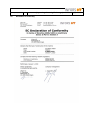
CE conformity declaration
INFORS equipments are CE-labelled from the factory and supplied with an EC
declaration of conformity. It can be found in the appendix of this manual, too.
INFORS equipment complies with the following Directives:
Directive on Machinery 2006/42/EC
EMC Directive 2004/108/EC
Quality Management Systems
All INFORS equipment is manufactured in accordance with INFORS’ quality
management system which is certified by BVQI in accordance with the
requirements of ISO 9001.
Testing
All INFORS equipment undergoes electro-mechanical operational testing before
it leaves the factory. The exact nature of the tests varies according to the
equipment type.
All equipment is delivered with a signed test certificate. The tests described are
conducted in accordance with the procedures set out in INFORS’ quality
management system and in accordance with international classification
companies.
Applicability
This is specified in the specifications table included within this section of the
document.
If any of these specific sections appears to be missing for your equipment please
contact INFORS and this can be rectified.
Please be aware that if the equipment is acquired second-hand from an original
user, it may have been modified, upgraded and enhanced such that some details
of the configuration may differ to those described in this manual. We will
provide any help and information necessary to bring the documentation up to
date but individual options may not be the standard ones supplied by Infors. In
this case, it is the responsibility of the previous owner to supply any additional
manuals, configuration information and safety-related items. INFORS disclaims
responsibility for all equipment that is not in original condition i.e.
modified by the user without prior agreement from INFORS.
page 3 of 53
January 11, 2010
(Operating-Manual_Minitron_e)
Identification plate
The identification plate is located on the housing of every piece of equipment
The identification plate must never be removed from the equipment.
If the name plate is removed, it is not possible to identify the equipment,
and it will not be possible for warnings contained in this manual to relate
to the specific applications for which the equipment is used.
page 4 of 53
January 11, 2010
(Operating-Manual_Minitron_e)
General Safety Points
NEVER open or remove covers (internal or external with the power
switched on.
No operations beyond those expressly stated in this guide are
authorised by INFORS as being suitable for the equipment.
All work on the equipment – including adjustments, repairs, pipe
couplings, etc. – must be undertaken by professionally qualified staff.
When repair and maintenance work has been completed, any safety
equipment provided must be refitted in its original state before the
equipment is started.
The equipment must be installed in accordance with the instructions
contained in this user manual.
The equipment’s weight is over the permitted allowance of
kilos/pounds that people may lift, so it must be lifted mechanically. –see
specifications sheet.
Users are responsible for ensuring that the equipment is used in
accordance with safety procedures applicable to their work and is free of
any biological or chemical contamination if an examination by INFORS staff
is requested.
INFORS will not be held responsible for any equipment which has been
improperly used, maintained, modified or repaired; nor for any
consequential losses arising.
All the housing covers of the basic unit and operating panel are, as
they may cover critical areas, only to be removed by personnel explicitly
authorised by INFORS to do so.
If in doubt about any aspect of the use of this equipment or its suitability for
an application, please contact INFORS.
Please ensure a Risk Assessment is carried out according to your
safety regulations before using the equipment
page 5 of 53
January 11, 2010
(Operating-Manual_Minitron_e)
Safety points relating to installation & use
Electrical connections should only be installed and fitted by a qualified
electrician to current electrical safety regulations.
Installation of all services lines should be made only with pressure
resistant tubing retained with suitable tubing clamps.
Authorization for use of an oxygen supply and its operation in accordance
with your own safety guidelines are the responsibility of the customer’
Never use the main ON/OFF switch to end operation!
Always work to GMP and observe other appropriate standards
Observe all safety issues relating to hazardous chemicals, biological
material and equipment under pressure, especially points regarding skin and eye
contact.
The equipment is only to be operated by suitably qualified and trained
personnel, both in terms of equipment use & microbiological expertise.
In normal use, operators should ware appropriate safety clothing, gloves,
safety goggles and a face mask as appropriate to the degree of microbiological
risk.
The nature of the microbiological and chemical risks associated with the
use of individual units cannot be assessed by the manufacturer and its
specification is the responsibility of the user.
The environmental hazards associated with the use of individual units
cannot be assessed by the manufacturer and its specification is the responsibility
of the user.
page 6 of 53
January 11, 2010
(Operating-Manual_Minitron_e)
Safety points related to testing the equipment
The main power switch should not be used as a functional ON/OFF.
Never put your hand into an operating unit – risk of injury due to high
rotational forces.
Handle glass vessels, reagent bottles and other glass components with
care to minimise the risk of breakage or other damage resulting is sharp edges
Do not apply excessive pressure when handling any glass components in
case of breakage and consequent sharp edges.
Ensure hair, loose clothing etc cannot come into contact with any rotating
parts.
Emissions and Warning indications
Any loud and/or unusual noise from any part of the equipment should be
taken as a sign of a problem and the equipment closed down and inspected
immediately.
Any smoke or smell of burning should be taken as a sign of a problem and
the equipment closed down and inspected immediately.
In normal operation, some additional noise and heat may be generated, the
extent depending on the phase of operation (see performance data)
Service & Maintenance
Only fully qualified and authorised persons may service the equipment
Cleaning and routine maintenance information in provided in the main manual.
page 7 of 53
January 11, 2010
(Operating-Manual_Minitron_e)
MINITRON ® - Incubator Shaker
Table of Contents
Chapter
1.
Safety Considerations
2.
2.1
2.2
2.3
2.4
2.5
2.6
2.7
Description of the Product, Technical Specifications
Comfort
Useful Space & Required Space
Technical description
Safety
Fittings
Dimensional Drawing
Technical Data
3.
3.1
3.2
3.3
Transport
Transport
Packing
Unpacking
4.
4.1
4.2
Location
In General
Chemical Resistance
5.
5.1
5.2
5.3
5.4
5.5
Interfaces
Electricity
External Cooling
External Gassing
Drain
Serial Port
6.
6.1
6.1.1
6.1.2
6.2
Assembly, Installation
Levelling of the MINITRON ®
Fixing and levelling the MINITRON ® with trolley base
Levelling the MINITRON ® with base support
Stacking
7.
7.1
7.2
7.2.1
7.2.2
7.2.3
7.2.4
7.2.5
7.3
7.4
7.5
Putting into Operation
Main Switch
Control Panel with Operating Display
General
Display
Operation
Timer
Operating hours counter
Over-temperature cut-out
Humidification
CO2
page 8 of 53
January 11, 2010
(Operating-Manual_Minitron_e)
Chapter
8.
8.1
8.2
8.3
8.4
8.5
8.5.1
8.5.2
8.5.3
8.6
8.6.1
8.6.2
8.6.3
8.6.4
8.7
8.8
Operation
Loading the Tray
Shaking speed
Starting the Apparatus
Opening the door, Pause
Application of the Tray and Handling of the Interior
Handling of the Shaker Contents without Removing the Tray
Removing the Tray
Inserting the Tray
Alarm function
Signal (Buzzer)
Alarm relay contact
Testing of the alarm function
Power failure (Message on Display “P Fail” !)
Serial Communication (RS 232)
Additional Safety Measures
9.
9.1
9.2
Putting out of Operation
Stopping the Shaker
"EMERGENCY"-Stop
10.
Trouble Shooting / Fault Rectification
11.
11.1
11.2
11.3
11.4
11.5
Maintenance / Service
Operating Hour Counter
Service
Cleansing of the Apparatus
Cleansing of Tray and Shaker Table
Opening of the Shaker Table
12.
Replacement Parts
13.
13.1
13.2
Additional Equipment, Options
Software
Points for Using Green Sticky Stuff
14.
Components from Suppliers
15.
15.1
15.2
15.3
Graphics, Overview
Identification Plate
Wiring Diagram
MINITRON ® fuses
16.
Reselling
17.
Disposal
18.
Example of temperature distribution in the incubation chamber
19.
19.1
19.2
INFORS-Agencies, guarantee regulations
INFORS Agencies
Guarantee
20.
21.
22.
Safety advice for working with CO2
Alarm description (from version V1.50)
Declaration of Conformity
page 9 of 53
January 11, 2010
(Operating-Manual_Minitron_e)
page 10 of 53
Copyright
You may not copy or duplicate any part of this manual without the prior written consent of INFORS AG
Switzerland.
Modifications
Due to the constant development and improvement of our products, the equipment supplied may differ from
the description in this manual. INFORS explicitly retains the right to make such deviations and
modifications.
Guarantee
You can find the guarantee in chapter 18.2.
1.
Safety Considerations
The MINITRON ® incubator shaker corresponds to modern demands for safe and easy-handling.
Any exposed current-carrying components (exception: lamps outside of the incubation chamber)
are low-voltage only, switching networks are physically separated and the chance of mechanical
injuries minimised.
Nevertheless, the following basic hints are indispensable for the safety of the user and the
protection of the machine. These hints, both here and in the following text, are printed
in italics in conjunction with a warning symbol (hand with pointed finger). They are to
be followed in every case.
All the housings and covers of the shaker are only to be removed by personnel explicitly authorised by
INFORS to do so. This is because safety-critical zones may be covered by housing panels.
The movement of the shaker table can cause injury due to the high torque when in operation. Therefore,
the tray is only to be handled when at rest.
The vent holes at the sides and in the back are not to be obstructed in any way. On no account allow
objects to become stuck in the fan or air intake openings.
The minimum distance has to be followed when installing the shaker.
Remove the transport security device before bringing the shaker into operation.
If rollers are attached to the shaker the front swivelling rollers have to be pulled so that they are
approximately 2-3mm above the level of the floor, with the machine resting on the static feet located
beneath the wheels.
During long absences or interruptions of operation, according to location (eg. humid laboratory or
unprotected position), it is recommended to withdraw the main power plug in order to avoid the risk of
accidents.
The shaker must never be operated without a tray.
The specifications in chapter “4.2. Chemical Resistance” have to be followed precisely.
January 11, 2010
(Operating-Manual_Minitron_e)
2.
Description of the Product, Technical Specifications
2.1
Comfort
page 11 of 53
In the same way as its successful "siblings" the UNITRON ® & MULTITRON ®, the downwards
opening door provides a convenient and practical place on which to rest the tray whilst exchanging
flasks.
The important features of simple operation and virtually silent running are guaranteed for a wide
range of applications in your laboratory, coupled with an attractive design.
A range of parameter set-points and timer functions can be programmed via a sensitive and
ergonomic splashproof operating panel eg. day/night cycling or switching between temperatures.
2.2
Useful Space and Required Space
Despite having a relatively small footprint, the MINITRON ® offers all the possible features required
in an incubator shaker. It provides space for cooling, lighting and humidification in addition to the
room required for a tray of 480x420mm.
Thanks to the downwards-opening front door, it is not only a bench-top shaker but can also be
located under a laboratory bench. In the best traditions of the MULTITRON ®, one unit can be
stacked on top of another. A substantial base support is used to raise the bottom unit when a
stackable system is assembled.
2.3
Technical points
After decades of experience of building magnetic drive systems, a completely new version has been
developed which is so well enclosed that liquids cannot penetrate.
The heating system for the incubation chamber guarantees a rapid and even temperature distribution
across the whole of the shaker tray. Supply of coolant is regulated for the most economical use of
energy.
The latest innovations in the field of micro processing and PID-regulation allow precise maintenance of
the set values.
The RS-232 interface for data logging and control is standard, as for all the latest Infors machines.
2.4
Safety
Additional operational safety is provided by an over temperature cut-out and a potential-free output
for linking to a central alarm system.
Following a power failure, the machine will automatically re-start using the current set-point on
resumption of the power supply.
Thanks to the sealed drive chamber and control electronics, the infamous consequences of
cleaning up following a flask breakage can be greatly reduced. As the walls of the incubation
chamber finish below the level of the shaker table, it is possible to rinse this area with water.
2.5
Fittings
In the most basic configuration, the MINITRON ® is provided with shaker, temperature and timer
functions.
Cooling can be supplied either from an external chiller connected to a cooling coil with magnetic
control valve or via an integral cooling system.
Optional extras include a gassing nozzle, daylight or photosynthesis lighting, CO 2 and
humidification control.
January 11, 2010
(Operating-Manual_Minitron_e)
page 12 of 53
A shelf is also available for static cultures within the incubation chamber eg. Petri dishes.
The “N” size table can has standard options for adhesive matting, clamps and/or test tube racks.
2.6
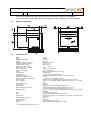
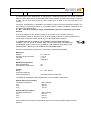
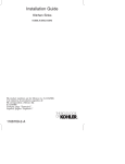
Dimensional Drawing
2.7
Technical Data
fig. 1
width
depth:
depth with opened door:
height:
incubation chamber: (h x b x d)
incubation chamber: (volume)
required footprint: (b x d)
weight without tray- cooling
weight without tray -no cooling
electric connection:
current consumption:
power:
rotation speed:
max. deviation:
temperature control:
temperature precision (Pt-100):
3)
temperature range : (without light)
3)
with ext. cooling :
3)
with int. cooling :
air circulation: (total)
heating power:
cooling power:
power capacity of the cooling
allowed humidity:
tray:
flask:
weight of tray:
allowed loading: (incl. tray)
dimension drawing:
order number:
Lighting:
3)
for outside temperature up to max. 30 °C
800 mm
674 mm
1105 mm
732 mm
410 x 555 x 495 mm
approx. 113 l
960 x 774 mm
90 kg
75 kg
230 V ± 10%, 50/60 Hz
approx. 6 amperes
approx. 750 watt (heating, excl. cooling)
see chapter 8.2.
1 % with maximal speed of rotation
electronic proportional action controller with Pt-100 probe
± 0.2 °C
5 °C over ambient temperature to 65 °C
depending on the temperature of the coolant and the environment
approx. 14 ± 1°C beneath ambient temperature up to 65 °C, but not under
5°C
3
110 m /h
500 watt
213 watt/hour at an evaporating temperature of 1 °C
105 watt at 230V/50Hz at an outside temperature of 32 °C
115 watt at 115/60Hz at an outside temperature of 32 °C
90 % r.H. at 37°C incubation temperature (controlled, if required, higher
available)
tray size N (480 x 420 mm)
according to the specifications of the customer
average value approx. 8.5 kg (depending on the size of the clamps and
the quantity)
see 8.2
see above
varies according to the type
Various spectral options available, if required
January 11, 2010
3.
Transport
3.1
Transport
(Operating-Manual_Minitron_e)
page 13 of 53
In view of the heavy weight of the MINITRON ® it should never be transported or moved by one
person alone. For displacements over longer distances within a building the use of a fork liT or a
small trolley is recommended. However the shaker is only to be moved by a fork lift if it is still
standing on the original palette on which it was delivered by the manufacturer. Also, transport on a
small trolley has to be effected with great care.
Danger of shearing off the shaker's feet and of collapsing the bottom plate in case of
exceptional stress. Therefore, never push the apparatus without lifting it.
Should it no longer be possible to transport the MINITRON ® using a small trolley it should be
carried by two adults using the two handles on each side. Weight without tray and cooling 75 kg.
3.2
Packing
Depending on the version and the destination the MINITRON ® shaker is either packed seaworthy
or placed on a large special palette. Non-polluting packing material was chosen in order to
minimize pollution.
3.3
Unpacking
Please be sure that the shaker, especially the window, will not sustain damage (scratches) during
unpacking.
4.
Location
4.1
In General
The following points have to be considered when choosing the location:
Protection from mechanical dangers (small trolleys, kicks, etc.)
For a shaker without cooling, the outside temperature should not be higher than 5 °C above
the desired minimal incubation temperature.
For a shaker with cooling the outside temperature should not be higher than 15 °C above the
desired minimal incubation temperature.
The outside temperature may not exceed 30 °C.
The machine should not be exposed to direct sunlight!
The surface on which the shaker stands has to be horizontal and absolutely flat.
The shaker should not be unprotectedly exposed to extreme masses of dust and dirt.
The control panel is not waterproof and must not be exposed to spraywater.
The optional base on which the shaker may be placed must be positioned safely and stable.
Please think of all the different connections you need for the interfaces.
The main switch must stay free and easily accessible.
(Operating-Manual_Minitron_e)
January 11, 2010
4.2
page 14 of 53
Chemical Resistance
The housing was tested with different solvents. With the solvents listed below neither a relevant
change of weight nor a change of the Shore D-hardness was found:
water
inorganic acids: phosphorus, nitric, hydrochloric or sulphuric acid, watery 10%
organic acids: formic, acetic and lactic acid, watery 10 %
inorganic bases: soda lye, at 10 % solution (aqueous)
inorganic chemicals in aqueous solution: hydrogen peroxide 10 %, calcium chloride saturated
solution, bleaching lye solution concentrated
hydrocarbons: fuel, motor oil, diesel
The housing should not be exposed to the following solvents in large quantities nor over a long
period of time:
methanol
ethanol
acetone
cyclohexanon
ethyl acetate
ethylglycolacetate
methylenchloride
The inner inspection window can be cleaned with a damp cloth and a normal neutral cleaner.
5.
Interfaces
5.1
Electricity
Sparkplug with a double protective system ("Europlug")
115/230 Volt +- 10 %
50/60 cps
5.2
External Cooling
The temperature of the coolant depends on the cooling system. We would like to point out that
temperatures of the cooling medium below freezing point may cause icing of the radiator grill.
Connection
internal width nipple 8 mm
internal width tube 10 mm
When using an external cooling the maximal pressure must not exceed 4.0 bar.
For a higher pressure, please contact an INFORS representative.
5.3
External Gassing
Connection
bore internal thread 1/4" with hose nipple
internal width nipple 8 mm
internal width tube 10 mm
(Operating-Manual_Minitron_e)
January 11, 2010
5.4
page 15 of 53
Drain
For security reasons the drain is supplied with a blind plug. A hose liner is enclosed with every unit.
Please install it (screw it in place) yourself.
Connection
bore internal thread 1/4" with hose nipple
internal width nipple 8 mm
internal width tube 10 mm
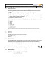
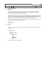
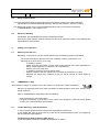
5.5
Serial Port
RS 232, 9-PIN
Standard PINs: potentialfree exit integrated into the RS 232 interface as control for the alarm (pins
1, 6, 7) contact 1-6 = observation, contact 1-7 = alarm.
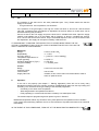
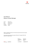
Connections at the rear of the unit
External Cooling
External Gassing
RS232
Drain
fig. 2
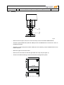
6.
Assembly, Installation
For special equipment the installation manual is printed on a separate sheet and is enclosed with
every unit.
Please make sure that the main switch is always freely accessible.
6.1.
Levelling of the MINITRON ®
When a unit on a base support is installed for the first time or an existing unit is moved to a new
location, the whole structure must be levelled to prevent vibration and mis-balancing.
January 11, 2010
6.1.1
(Operating-Manual_Minitron_e)
page 16 of 53
Levelling of the MINITRON ® with movable base
- Pull the front, swivelling wheels so that they are approximately 2-3mm above the level of the
floor, with the machine resting on the static feet located beneath the wheels.
- To level the movable base, adjust the orange nut on the front wheels.
- Start all shakers at 100 rpm and look for any rocking or obvious vibration of the machine.
-
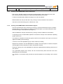
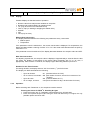
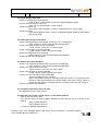
6.1.2
Also refer to the instructions given in Sections 6.1,2 & 3.
Levelling of the MINITRON ® with fixed base support
- The front, left-hand foot can be moved up or down by a screw thread with the help of an SW12
spanner (item 2). First, a locking nut at the top of the thread (item 1) must be loosened to allow
movement using an SW18 spanner (see figure 3)
-
Start all shakers at 100 rpm and look for any rocking or obvious vibration of the machine.
-
If everything is OK, increase shaker speeds in increments of 100 rpm to the maximum operating
speed of each unit.
-
If movement or vibration is found at any speed, look for the foot which is too high or too low and
adjust the levelling foot accordingly.
-
To do this, screw the adjustable leg up or down a little as necessary.
-
Repeat this procedure until the MINITRON ® is steady at the test speed. Increment the speed
and test again until the maximum for each unit has been reached.
-
Ensure the locking nut on the adjustable foot has been tightened before allowing normal use of
the machine.
-
For a particularly slippery floor surface, the use of small friction pads under each foot of the
MINITRON ® is recommended.
-
Any vibration or movement during normal use must be reported so a re-levelling can be carried
out.
January 11, 2010
6.2.
(Operating-Manual_Minitron_e)
page 17 of 53
Stacking
fig. 3
Remove the four caps on the four corners of the top cover of the bottom MINITRON ®.
Screw the special EMF"bolt" (Part No 24646) onto the threaded bolt on the left rear corner on
the bottom machine.
Screw the 3 other bolts (Part number 24635) into the remaining corner threaded bolts on the
bottom machine.
Mount the upper unit onto the lower.
Remove the covers from the left and right sides of the top unit (see figure 4).
Screw in the M6x16 retaining screws to secure the locating bolts in place.
Covers
(2 per side)
fig. 4
January 11, 2010
7.
Putting into Operation
7.1
Main Switch
(Operating-Manual_Minitron_e)
page 18 of 53
The main switch of the shaker is located on the right side wall. It is an ON/OFF selection switch
which has to be turned on (position ON) first of all. If you turn off the switch (position OFF) the
shaker is completely separated from the power system.
It is possible to leave the main switch on during normal operation even if neither shaker nor heating
are working. In this "Stand-by" position the shaker consumes approx. 6 Watt. Frequent turning on
and off (e.g. every hour) should be avoided in order to minimize stress of the electronic parts. If the
shaker is not used for several days we recommend you switch off at the mains switch.
The set points of all parameters (temperature, speed, timer, lights) are memorized after turning off
the main switch or during an interruption of current.
7.2
Operating Panel
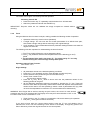
7.2.1.
General
Several parameters are set with the help of the operating panel, which is located at the top right of
the machine.
The panel comprises:
5 Keys
1 alphanumeric display
9 icons for:
timer functions
Power
Speed
Temperature
Humidification
Lights
The icons are only visible when activated.
(Operating-Manual_Minitron_e)
January 11, 2010
page 19 of 53
Keys
Function Key "current phase"
Plus Key
On/off Key
INFORS AG 4103-BOTTMINGEN
F
FT
CO2
RPM C°
Function Key "nexT phase"
FT
Minus Key
fig. 5
There are two different groups of icons:
Parameter
These light when the corresponding value is shown on the display, during which the set point
values can be changed for that parameter. They are:
The lights diode
The speed diode
The temperature diode
The humidity diode
The power diode, which comes on when the mains switch is turned ON
If the parameters humidity, light and CO2 have not been installed, they can not be selected.
Timer
These are shown during the display and programming of the various timer functions. They are:
The "Duration" diode, which lights when this value is to be changed
The "Timer" diode lights when the timer function is switched ON.
The "Cycle" diode is on when the unit is set to operates by switching between two different sets
of operation conditions eg. day and night simulation
The "NexT phase" diode lights when the non-current (later) time phase is being programmed.
(Operating-Manual_Minitron_e)
January 11, 2010
7.2.2
page 20 of 53
Display
Possible displays in Standard mode of operation:
Numeric value for actual process variables or set-points
Numbers and symbols relating to operating hours
"ini" (only when the unit is first switched on)
"Sta" or "Stp" (on starting or stopping the shaker drive)
ON/OFF
hi/lo
Time (only for timer)
Without User Intervention
The display alternates between the following two parameters every 10 seconds:
Shaker speed
Temperature
If the parameter control is switched on, the current actual value is displayed. For temperature, the
display will also indicate a warning of either "hi" or "lo" if the actual value deviates from set point by
more than 1.5oC.
If the parameter control is switched off, the display alternates between the set-point value and OFF.
With User Intervention
On adjusting a parameter, the set-point value is displayed. Approximately 2 seconds after the last
key press, the display is exchanged for the actual value (eventually with "hi" or "lo" also, if
appropriate). After a further 10 seconds, the display begins alternating between rpm and oC.
Duration for the Timer function
For setting duration, the display shows a "tick" for minutes ( ' ) and h for hours.
The display can alternate between the following:
Up to 99 minutes:
99' (numbers before the "tick")
UP to 9 hours, 50 minutes: 9h5 (first number for hours, second for increments of 10
minutes)
Up to 95 hours:
95h (numbers before the "h")
UP to 9 days, 23 hours:
9.23 (whole numbers for days, decimal value for hours)
7.2.3
Operation
Before switching each Parameter on, the set-points must be entered:
Entering the Values for RPM, oC, Humidity & Lights
Press the function key "F" repeatedly until the desired icon is illuminated
Enter the required set-point value using the Plus and Minus keys. For lights, the only
possible options are ON or OFF.
(Operating-Manual_Minitron_e)
January 11, 2010
page 21 of 53
The control can be given concurrently with this operation.
Switching Control ON
Press the function key "F" repeatedly until the desired icon is illuminated.
Switch the parameter ON with the ON/OFF key.
IMPORTANT: Set-point values are not validated but simply accepted as entered without
checking.
7.2.4
Timer
Using the Minitron timer functions is simple, making possible the following modes of operation:
Operation without any timer functions (standard)
A single change. The unit runs with the chosen parameters for a definite time span,
then makes a single change without returning to the original settings.
Cyclic operation. The unit alternates all active parameter settings between two states at
regular time intervals.
The following rules are important for understanding the timer functions:
1. The "F" key ALWAYS sets the current parameter values
2. The "FT" key ALWAYS sets the relevant parameters for the following (or nexT)
phase
3. The unit always finds itself in the phase "F". The values set by "FT" are only
utilised when (if) the next exchange actually takes place.
Operation without Timer Function
See Section 7.2.3.
Single Change
All parameters are set to the desired operating conditions
Press the "F" key repeatedly until the Timer Duration symbol is lit (Hour)
Set the duration of the phase using the Plus and Minus keys
Switch Timer control to ON
The hourglass begins to blink
Press the "FT" key. The FT diode is shown and now the parameter values for the
following phase can be given.
All the alternative parameter values are accepted by pressing the "F T" key. These will
become active after the previously defined time interval has expired. Either alternative
values can be used or it is also possible to switch control of parameters OFF (eg. After
12 hours the temperature is reduced to 4oC and the shaker drive switched off)
WARNING: Don't forget that as well as entering set-point values, the control for each desired
parameter also has to be switched ON! The Display of the set-point value switches to OFF or ON
to indicate if the control is switched on or off.
Timer function in the "FT" phase is not switched to ON, as this starts cyclic operation.
End (the FT diode goes out after a short time)
If you wish to know when the current phase expires, press the "F" key until duration time is
selected once more. The time remaining is then shown in the display. A single key press of the
Plus or Minus key shows the original set time for the current phase.
(Operating-Manual_Minitron_e)
January 11, 2010
page 22 of 53
NOTE: press more than once and the set-point time is shown once again. By pressing the key
ON/OFF twice, the timer can be reset.
Cyclic Operation
All parameters are set to the desired operating conditions (eg. lights ON)
Press the "F" key repeatedly until the Timer Duration symbol is lit (Hour)
Switch Timer control to ON
The hourglass begins to blink
Set the duration of the phase using the Plus and Minus keys
Press the "FT" key. The FT diode is shown and now the parameter values for the
following phase can be given.
All the alternative parameter values are accepted by pressing the "F T" key. These will
become active after the previously defined time interval has expired (eg Lights OFF).
WARNING: Don't forget that the as well as entering set-point values, the control for each desired
parameter also has to be switched ON!
Enter the duration for the following (nexT) phase
Switch ON the Timer control in the "FT" phase
The cycle icon lights
End
7.2.5
Operating Hour Counter
See Section 11.1
7.3
Over-temperature Cut Out
The MINITRON has a temperature "watchdog" to prevent uncontrolled overheating of the machine.
This is set to 80°C.
7.4
Humidity
The operation is the same as for the other parameters (see 7.2.3). Please make sure that the
supply is connected:
- Water with max. 1 bar pressure (0.5 bar is sufficient)
- Hose connected
- Water on
This option is used for sequential control of relative humidity in the range of 55-85% rH in
temperature controlled incubation chambers. Relative Humidity means: the capability of the air to
absorb water depends strongly on the temperature. After an increase of the temperature setpoint,
the relative humidity will go down until the system supplied enough water. On the other hand, after
a strong decrease of the temperature setpoint the relative humidity will rise to 100% and even
condensation might eventually occur inside the chamber. The humidification system works actively
only in one way, it does not perform a de-humidification. For this reason it is possible that after a
strong decrease of the temperature setpoint the alarm “Humidity HI” will be displayed for a longer
period of time. In this case, open the door to let the moist air escape.
If there should be a lack of water, the alarm “Err” and the humidity diode light up. In this situation
the humidity control will be automatically turned off.
Caution:
Only use demineralized (soft) water! The use of tap water will lead to a breakdown
of the system. On the other hand, distilled water is very aggressive and will shorten
the lifetime of the vaporizer membranes.
The spray device of the humidification system must be cleaned with vinegar only!
January 11, 2010
(Operating-Manual_Minitron_e)
page 23 of 53
The bottom part of the MINITRON® is designed as a watertight well which can accept condense
water or culture liquid after a flask breakage without any damage to parts of the machine. Removal
of water can be done easily using the drain nozzle which is fitted on the left hand side of the
housing.
The option “humidification” is available in two different versions: with and without door heating. If a
door heating is necessary depends on the gradient deltaT between Incubation Temperature (IT)
and Room Temperature (RT):
IT – RT > 15°C: Door heating is highly recommended to prevent condensation on the door
window!
A very high setpoint for the relative humidity of up to 100% is not necessary and is not
recommended. Usually, a setpoint of 70% rH will be entirely sufficient to prevent evaporation of
culture liquid. A setpoint of 85% should only be used under ideal conditions!
IF CONDENSATION OCCURS IN THE CHAMBER THE MAXIMUM POSSIBLE
HUMIDITY OF THE AIR IS REACHED AND THE SETPOINT MUST BE REDUCED.
OTHERWISE IT WILL LEAD TO A FAILURE OF THE HUMIFICATION DUE TO AN
PREMATURELY WEAR OF THE HUMIDIFICATION MEMBRANES!
While the humidification is switched on, the cooling is automatically disabled.
Measuring
Ranges
Accuracy at 20°C at 54%rF
Indication
Probe
20…100% rH
3% rH
1% rH
Capacitive
Maximum Temperature
With humidification
Humidification switched off
40°
65°
Control
Range
Control by Vaporizer
Water Inlet Pressure
20….max. 85% rH
max 1Bar (0.5 Bar is sufficient)
The maximum available humidity depends also on the incubation temperature:
System without door heating
Incubation temperature
27°C
33°C
37°C
Max. Humidity
85% rH
80% rH
70% rH
System with door heating
Incubation temperature
27°C
33°C
37°C
Max. Humidity
85% rH
85% rH
85% rH
If these values are exceeded, condensation might occur and the humidity setpoint must be
reduced.
January 11, 2010
7.5
(Operating-Manual_Minitron_e)
page 24 of 53
CO2
The operation is the same as for the other parameters (see 7.2.3). Please make sure that the
supply is connected:
- CO2 gas with max. 0.5 bar pressure, flow 40-60 lt/h
If the pressure of the gas supply is too high the control will show a „shoot over“ and the actual
value will oscillate around the setpoint! An adjustment of the flow without a control valve can be
achieved following this procedure:
Connect a hose to the CO2-supply and put the loose end in a beaker with water. Open the supply
carefully until bubbles rise up in the beaker with a frequency of about 1-2 bubbles per second.
Then, connect the hose to the machine. Only if the desired setpoint of CO2 can not be reached with
this adjustment, the supply can be opened carefully a little bit more.
IT IS IMPORTANT TO ENSURE THE DOOR IS FULLY CLOSED WHILE USING THE CO2
OPTION, OTHERWISE IT WILL LEAD TO A HIGH CONSUMPTION OF GAS. FOLLOW THE
SAFETY ADVICES IN THE APPENDIX!
Measuring
Ranges
Repeatability
Accuracy at 25°C
Temperature dependence of
output (typically)
Pressure dependence (Typic.)
Long-term stability
Control
Range
Control by Valve
Inlet Pressure
Supply Gas CO2
8.
0-10% or 0-20% CO2
<+- 1%FS
+- [1%vFS + 1.5% of reading]
0.1%FS/ °C
0.1 FS/ hPa
< +- 5%FS/2 years
0-10% CO2 or 0-20% CO2
max. 0.5 Bar
40-60lt/h, a flow control valve is recommended in order to
reach an optimal control
Operation
If the unit is set properly (see chapter 7. ‘Starting Apparatus’) there will not be many many
alterations necessary during the ordinary operation of MINITRON ® apart from the tray loading and
unloading. The unit will be running according to the selected programme:
Constantly in the same mode of operation
Alternating between two operational modes or
Firstly operating in a timed mode and then constantly in a subsequent mode
The relevant steps for programming these options is given in Section 7.
MINITRON ® operates without any emissions of any kind apart from the operational sound. Sudden
noise, smell, abnormal strong vibrations and so on are indicators of a problem and have to be examined
immediately.
IN THE EVENT OF SUCH EMISSIONS, TURN OFF AT THE MAINS SWITCH IMMEDIATELY.
(Operating-Manual_Minitron_e)
January 11, 2010
8.1
page 25 of 53
Loading the Tray
A counterweight works to compensate the centrifugal forces of the moving tray.
For physical reasons this counterweight has to be balanced for a certain tray weight.
Equally important is the height of the centre of gravity of the shaken load above the tray (high load
= higher centre of gravity, low load = lower centre of gravity). The higher the total height of the
load, the more the unit can vibrate.
Although INFORS has optimised the band width of the possible loading, the following points should
be respected in order to minimise possible wearing:
- Always load the tray as evenly as possible, so that the weight of the flasks is spread over the
whole tray.
- Flasks with an extraordinary height and an extremely high centre of gravity should not be
shaken at too high a speed.
- The allowed loading should generally not exceed or remain under the following values:
An under or over loading around these values does not have an acutely damaging effect on the
unit (especially at low speed) but should be avoided if possible.
A constantly higher or lower loading is possible but you have to contact a representative of
INFORS first in order to obtain the necessary advice.
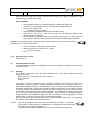
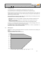
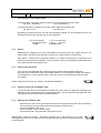
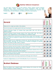
8.2
Shaking speed
The maximum rotation speed allowable depends on the position, the diameter and the loading (see
above).
Weight: tray, clamps, flask and medium
The following standard values must be observed:
12 kg
11.5 kg
11
kg
10.5 kg
10
kg
9.5 kg
9
kg
8.5 kg
8
kg
7.5 kg
7
kg
6.5 kg
6
kg
5.5 kg
5
kg
4.5 kg
4
kg
3.5 kg
3
kg
2.5 kg
2
kg
1.5 kg
1
kg
0.5 kg
0.0 kg
0
50
100
150
200
250
300
350
400
fig. 7
January 11, 2010
(Operating-Manual_Minitron_e)
page 26 of 53
It is possible to achieve higher rotation speed, however the customer has to contact a
representative of INFORS first in order to obtain the necessary advice.
With the stacked Minitron version vibrations can occur at a higher rotation speed (300-400 rpm)
although the load limit has been controlled as in the diagram. This appears when both units run
with almost the same rotation speed.
AT HIGHER SPEED (>200 RPM) WITH LITTLE LOAD, FLASKS WITH WATER SHOULD BE APPLIED
TO BALANCE THE TRAY!
8.3
Starting the Apparatus
see chapter 7. ‘Putting into Operation’
8.4
Opening the Door, Pause
When the door opens, the shaker brakes gently and comes to a complete stop (unless the brake
function has been deliberately de-activated by the user). The working light goes off. As soon as the
shaker platform is still, the tray can be handled.
The temperature control and the blowers stop working when the incubation chamber is opened in
order to avoid an internal environment change and reduce energy costs. The operational lights also
go out automatically.
If you close the door the blower, and the set-point control, will automatically start working again
after a brief delay.
8.5
Application of the Tray and Handling of the Interior
8.5.1
Handling of the Shaking Load Without Removing the Tray
-
Stop the Shaker temporarily (open door slightly)
Wait until the motor has come to a complete stop
Open the door
Manipulate the shaker contents
Close the door again
The shaker starts operating again automatically
ATTENTION: The moving shaker table can cause injuries because of the considerable torque.The tray is
therefore only to be handled in state of rest.
8.5.2
Removing the Tray
-
Stop the machine temporarily (open the door slightly)
Wait until the motor has come to a complete stop
Open door to an angle of 90°
Remove the retaining screw at the front of the tray
Pull out the tray at the handle along the guide rails
ATTENTION: The moving shaker table can cause injuries because of the considerable torque.
The tray is therefore only to be handled in state of rest.
(Operating-Manual_Minitron_e)
January 11, 2010
8.5.3
page 27 of 53
Inserting the Tray
The insertion of the tray functions independently of the position of the shaking table. Note the
following rules:
- Put the tray between the two lateral guide rails
- Push the tray on the platform in the incubation chamber up to the end stop.
- Make sure the tray locks right in both cones.
- Fix tray with retaining screw.
- If the tray cannot be pushed into the proper position, remove the tray and check it for distortion
and curves.
- If the shape of the tray is normal, search for items lost in the incubation chamber and remove
them.
- If the tray still cannot be positioned properly please contact the nearest INFORS dealer.
- The shaker restarts automatically if the tray is positioned properly
NEVER START THE SHAKER IF THE TRAY IS NOT INSERTED CORRECTLY!
The door is designed to resist to forces which result from normal service (e.g. weight of a
tray loaded according to instructions). Under no circumstances should you use the door as
charging space for heavy weights or even as a seat. Such stress may cause damage to the
shaker.
8.6
Operational and Working Lights
A single press of any key on the operating panel will switch on the working light in the incubation
chamber. This light only has an observation function. The working light automatically goes out after
approximately 1 minute.
8.7
Alarm functions
MINITRON
®
distinguishes between alarms and errors:
Alarm: Setpoint is not reached
Mostly operating error!
See below for a trouble shooting guide
Error (Malfunction): Display shows „Err“
Shaker blocked or some part defective
Continue in chapter 10
In the case of errors (display shows Err) please see chapter 10 „Trouble shooting“.
Alarms:
An alarm will not occur on opening or closing the door and if the value of the respective parameter is
rising/falling with normal speed. The alarm will occur only if a desired set point is not reached. Then, the
alarm relay switches and opens the contact. It is not necessary to confirm an alarm, it will disappear as
soon as the condition triggering the alarm is no longer fulfilled.
The display will show the message “HI” or “LO” respectively as long as the actual value of the
corresponding parameter shows a deviation from it’s setpoint for more than one unit (°C, RPM or %).
(Operating-Manual_Minitron_e)
January 11, 2010
page 28 of 53
If an alarm occurs the reason is mostly an operating error and can be corrected easily:
Function
Display
Description
Description
Temp
LO
Temperature remains too low
after a time (deviation > 1°)
and is not increasing
Over-temperature safety switch open or
ventilators not running. Door not fully closed.
Temp
HI
Temperature remains too high
after a time (deviation > 1°)
and does not decrease
External Cooling: valve closed or ventilators
not working
RPM
LO
The speed does not reach set
point
Loading too high. Drive belt is loose or
greasy.
RPM
HI
The speed is above the set
point
Resonance effect. Control problem.
CO2
LO
CO2-concentration is too low
after some time (deviation >
1%) and does not rise
CO2-valve blocked or closed. Bottle empty.
CO2
HI
CO2-concentraiton is too high
after some time (deviation
>1%) and does not sink
Gas pressure too high, control overshoot
Humidity
LO
Humidity is too low after some
time (deviation > 10%) and
does not rise
Door not fully closed. Vaporizer defective/
membrane worn out. Fuse Humidification
burned.
Humidity
HI
Humidity is too high after
some time (deviation > 10%)
and does not sink
Strong decrease of the temperature setpoint. Open the door to let the moist air
escape.
IF A SETPOINT IS NOT REACHED AND THERE IS NO ALARM OR ERROR, PLEASE CHECK IF
THIS PARAMETER IS SET TO “ON” (see 7.2.3)!
8.7.1
Alarm relay contact
The alarm relay shows an existing error or an alarm and can be connected to a central alarm system to
provide acoustic indication and/or optical display. The alarm relay constantly indicates an existing error
or alarm condition. In the event of a power failure, alarm or error conditions contact on PIN 1-7 of the
serial port is closed, contact on PIN 1-6 is open.
8.7.2
Testing of the alarm function
For testing the function of the alarm or the alarm relay, follow this procedure:
Set the Temperature to a very low value (e.g. 0°C, see chapter 7.2). Block the door in a slightly open
position, e.g. by placing a folded peace of paper in the gap. The machine will not be able to reach this
setpoint and the alarm will occur after some time.
8.7.3
Power failure
In the event of a power failure, the alarm relay closes and all functions (RPM temperature control etc.)
cease. As soon as the power is restored, the machine immediately re-starts using the previous set-point
values. The alarm relay operates normally again.
January 11, 2010
8.8
(Operating-Manual_Minitron_e)
page 29 of 53
Serial Communication
For information about serial communication and control please contact your nearest INFORS
representative or INFORS Switzerland directly. Also see the diagram in Section 5.5 (fig 2).
For display and control of one or several MINITRON ® we offer you as option the software
"LABWORLDSOFT" (see chapter 13.1).
8.9
Electronic Breaking
As standard, the MINITRON has electronic breaking activated.
Should very shear-sensitive cells be cultured, this can be de-activated. Please contact INFORS AG
Switzerland for further details.
9.
Putting out of Operation
9.1
Switching the Unit OFF
Depending on the time the unit is to be left switched off, the following options are available
A short stop intending to allow access to the incubation chamber (see Section. 8.4
Switching off for some hours, up to a day
In addition to Pause
Switch off at the main switch (control need not be switched off for each parameter if it
will be needed again the next time the unit is operational).
Switching off for a longer time
In addition to switching off at the mains switch
Clean the inside of the unit, (liquids can accumulate at the bottom over time)
Withdraw the mains plug, especially if the unit will be unused for some weeks or
months.
9.2
"EMERGENCY"-Stop
Should there be danger for humans and /or the shaker turn off the main switch immediately.
Danger may especially arise when there are sudden unusual emissions (loud noise, smoke, smell,
strong vibrations).
After an "EMERGENCY"-stop please note the following:
- Avert the danger (in case it still exists)
- If a repair is necessary to the shaker or if the cause of the emergency cannot be found, please
contact your nearest INFORS representative.
10.
Trouble Shooting / Fault Rectification
In case of trouble please read the following list and follow the instructions.
If your shaker still does not work correctly or the fault is not listed please contact your supplier or
the next INFORS representative.
The Operational Display Shows "ERR" (Error)
In this case please contact an INFORS representative for repairs.
January 11, 2010
(Operating-Manual_Minitron_e)
page 30 of 53
The Large Display Stays Dark
- Check if the working light still functions
if NO continue, if YES please contact your nearest INFORS supplier
- Check if the main switch is turned on
if NO: turn it on and try again, if YES continue
- Check the power cord
if the power cord is plugged in: continue, otherwise plug it in and try again
- Check the socket
if the socket supplies current: contact an INFORS supplier, otherwise eliminate the
fault and try again
The Heating/Cooling Does Not Work
- Check if the large display shows "ERR" and the icon for oC is displayed
if NO: continue, if YES: contact INFORS representative
- Check if the heating/cooling control is activated
if YES: continue, if NO: turn it on and try again
- Check if the set point is correctly adjusted
if YES: continue, if NO: adjust it and try again
- Check the ventilator fans are operating
if NO: continue, if YES: contact INFORS representative
- Contact an INFORS representative
The Shaker Drive Does Not Work
- Check if the large display shows "ERR" and the icon for RPM is lit
if NO: continue, if YES: contact INFORS representative
- Check if the motor control is activated
if YES: continue, if NO: turn it on and try again
- Check if the set point is correctly adjusted
if YES: continue, if NO: adjust it and try again
- Check if you can manually turn the shaker table
YES it is possible to turn it: continue
NO it is not possible: dismount the shaker table (see Section. 11.5) and search the
interior for mechanical obstacles and foreign matter. Remove the foreign matter. In
case a new test results in no improvement or no foreign matter is found: continue
- Contact an INFORS representative
The incubation illumination does not work
- Not applicable to the current machine
The table does not locate on both 'Cones" on the shaker platform
Take out the tray and try again
If the tray still does not locate properly, withdraw the tray and turn it over to check for any
warping
Tray is normal: Continue
Tray in twisted: Continue
- Contact an INFORS representative
NEVER START THE SHAKER WHEN THE TRAY IS NOT PROPERLY LOCATED AND IS
NOT LOCKED WITH A HAND NUT !
(Operating-Manual_Minitron_e)
January 11, 2010
page 31 of 53
The Parameter Values Cannot Be Reached
Check if the control of the concerned function (temperature, speed or light) has been activated (see
Section 7)The °C and/or the RPM-LED light up if the control is activated.
Operating Mode/Timer Function Cannot Be Programmed
Follow every instruction systematically. Complex programming steps should not be taken in a hasty
way i.e. you should wait for the results before you continue.
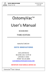
11.
Maintenance / Service
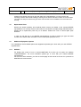
11.1
Operating Hour Counter
The operating hours display can show the following three times:
Operating hours for the motor drive control
Icons "Timer" and “RPM” lit
Operating hours for the temperature control
Icons "Timer" and “oC” lit
Operating hours for the time the mains switch has been ON.
Icon "Timer" lit
Timer
N
E
G
N
IM
T
T
O
B
-3
0
1
4
Function key Current Phase
F
FT
CO2
RPM C°
FT
G
A
S
R
O
F
N
I
Power
fig. 8
Speed
Temperature
Function key NexT Phase
The following steps are employed to activate the operating hour counter:
Press the "F" key (keep the key depressed)
Press the "FT" key (keep the key depressed)
Thereupon, the operating hour counter will cycle between the three possible displays.
Each part of the overall display switches between two types of displayed value.
(Operating-Manual_Minitron_e)
January 11, 2010
page 32 of 53
The meaning of each display phase
In the first phase, the display shows thousands of hours expressed as 00.0 to 99.9
Eg. 00.5 = 5000 Hours
10.3= 103,000 hours
In the second phase, hundreds of hours are shown expressed as 000 to 999.
Eg. 005=5 hours
163=163 hours
By adding the values from the first and second display together, the total operating time for the
parameter shown by the relevant icon can be determined:
Eg. The first phase
The second phase
TOTAL
11.2
= 01.4 = 14,000 hours
= 042 =
42 hours
= 14,042 hours
Service
MINITRON ® is designed as a service-free shaker and does not need any regular services. The
shaker table works with closed bearings, the electronic system needs no maintenance.
After approx. 10.000 hours of operation however, we would recommend an overhauling of the
shaker by the specialists of INFORS. You are invited to contact your INFORS representative when
your shaker reaches this operation time.
11.3
Cleaning the Apparatus
You can clean the apparatus with a damp cloth and a normal neutral cleaner without any
difficulties. We recommend to take off the shaker platform only if liquids were spilled on the bottom
of the apparatus e.g. from a broken flask. In this case, remove the platform and clean the base
accordingly.
Please observe the instructions in chapter "4.2 Chemical Resistance".
11.4
Cleaning of the Tray and Shaker Table
The tray and the table can be cleaned in the same way as the rest of the apparatus. But after every
cleaning, the two cones and the two corresponding holes in the tray should be lubricated with a thin
lubricating film (use Molikot paste or similar lubricants)
11.5
Opening of the Shaker Table
-
Detach the two rear screws (countersunk screws with hexagonal recess M5 x 16) as well as the
two front screws (cheese-head screws with hexagonal recess M5 x 20)
remove the platform (with cone)
Clean the bottom, remove foreign matter
Put the table (with cone) back down and replace screws
IMPORTANT: Tighten the screws * alternating crosswise (as for the wheels of a car). Onesided tightening of the screws may cause poor fixing of the table and thus considerable damage
to the apparatus.
January 11, 2010
(Operating-Manual_Minitron_e)
page 33 of 53
Cleaning of the bottom well can be done with water and a mild detergent. In order to remove the
remaining nutritions after a flask breakage, washing out the bottom well with hot water is recommended.
The water can easily be drained using the hose connector that can be installed on the back side of the
housing.
12.
Replacement Parts
Should your shaker suddenly show defects please contact your dealer or the nearest INFORS
representative. For security reasons and because of the shaker’s complex design INFORS offers a
detailed list of replacement parts only to its dealers. Please find a list of normal spare parts
attached.
In case you will ask one of our INFORS representatives for advice please give type and serial
number of the shaker. Both are written on the number plate (see point 15.1).
13.
Additional Equipment, Options
For a detailed list of all available options and supplements please get in touch with your next INFORS
representative.
13.1
Software
For display and control of one or several MINITRON ® we offer you as option the software
"LABWORLDSOFT". For more information please get in touch with your nearest INFORS
representative.
For the use of other software, you find on the last page of this manual a voucher for a protocol for
MINITRON ® communication.
January 11, 2010
13.2
(Operating-Manual_Minitron_e)
page 34 of 53
Points for Using Sticky Stuff
Always use protective goggles and gloves while handling
glassware!
Only use containers with a wide, flat base. Large Erlenmeyer
flasks (e.g. 3000 mL) will stick stronger than small ones (e.g.
100 mL)
Before putting on the INFORS reagent tubes holders, clean the
Sticky Stuff to esure the maximum adhesice power.
Before putting on containers:
Check that bottom is dry and clean
Check flask for any damages:never use damaged flasks!
Before shaking:
Tug gently to ensure each flask is stuck.
Keep in mind that formation of condense water might occur at low
temperatures or using the timer function, possibly causing accidental
release of containers.
To remove flask:
Push or pull neck gently and evenly and wait a few seconds. Do
not use much power!
With large containers, it can take up to 30 seconds until flasks is
released.
Flasks which are firmly attached can be released with water.
Simply apply water with a syringe to the bottom.
Especially Fernbach-flasks are difficult to remove because of their
geometry (large bottom, short neck), therefore cover the adhesive
matting partly with the protective foil supplied with each new tray.
The adhesive power will diminish gradually, due to dust and dirt sticking
on the surface. To regenerate proceed as follows:
Clean regularly with water and mild detergent. Shrub vigorously with
a brush or hard sponge. Do NOT use solvents!
Let dry over night
Disinfection with 70% ethanol or usual disinfectants.
Do not exceed specified treatment times and rinse thoroughly with
water. If disinfection is done routinely, it might be necessary to
replace the Sticky Stuff earlier.
It is possible to apply the Green Adhesive Matting “Sticky Stuff®” to
universal trays.
(Operating-Manual_Minitron_e)
January 11, 2010
0
page 35 of 53
Changing of adhesive matting:
Thoroughly wet the tray
Release Adhsive Matting on a side and pull obliquely away from the
tray. Deagrease tray with Acetone and apply new matting with
water (see installation instructions). Do not remove protective foil
until first use.
The Adhesive Matting is reusable and can be applied again after
regeneration in water.
Max shaking speed
Angabe
Wert
25 up to
Max. 200 rpm
750 mL
1000 mL
Max. 250 rpm
2000 mL
Max. 250 rpm
3000 mL
Max. 300 rpm
5000 mL
Max. 250 rpm
14.
Maximum shaking speeds are only valid on condition that:
Only original Schott Duran Erlenmeyer flasks with 20% filling volume
and paper- or cotton stoppers are used. Plastic Erlenmeyer flasks are
not appropriate for use with the adhesive matting.
Glass and Adhesive matting must be totally undamaged, clean, dry and
free of grease.
All information supplied without liability.
Data in the left column are valid for 50 mm shaking diameter. With 25 mm
shaking diameter, slightly higher shaking speeds are possible
Components from Suppliers
All the components from suppliers have been tested before the constructional implementing into
the INFORS product. As a general rule INFORS uses only proven components.
In exceptional cases faults may still occur in suppliers' products. In such cases INFORS cannot
take any liability leading further than the normal warranty. We kindly ask the customer for
understanding and will of course do our best to keep the highest quality standard possible.
The above mentioned exclusion of liability is not effective for safety issues.
January 11, 2010
(Operating-Manual_Minitron_e)
15.
Graphics, Overview
15.1
Where to Find the Identification Plate (Serial No., Type etc.)
page 36 of 53
Identification plate below the door
fig. 10
January 11, 2010
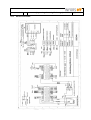
15.2
Electrical schematic
(Operating-Manual_Minitron_e)
page 37 of 53
January 11, 2010
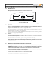
15.3
(Operating-Manual_Minitron_e)
page 38 of 53
MINITRON ® Fuses
Both fuses are identical and located above the power cable inlet socket.
Fuse type: T 6.3 A, slow blow fuse
Two fuses, 250V: T 6.3 A
16.
fig. 11
Reselling
For reasons of operating reliability, for legal reasons, in order to ensure a smooth maintenance and
supply of replacement parts and to protect the intellectual property of INFORS the customer is
obliged to inform INFORS in case of resale or change of the owner.
As a service in return for this information INFORS offers, if necessary, support for the new
installation as well as the training of the new operator.
Should a customer not fulfil this duty INFORS reserves the right to henceforth refuse any possible
maintenance or supply of replacement parts.
Disposal
17.
The plastic housing of MINITRON ® is produced without CFC elements. It consists of polyurethane
and a normal disposal is possible.
Also elements like the motor, blower, flywheel etc. may be treated the same way.
Please make sure that the coolant will be handled correctly (freezing mixture R 134 a) in the event
of disposal of the refrigerator. The whole cooling or at least the cooling fluid should be handed over
to an official handler.
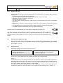
18.
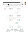
Example for the temperature distribution in the incubation chamber
If the temperature distribution in the incubation chamber is to be checked, it is necessary to strictly follow
the protocol given below, otherwise the measured values will be wrong. Especially the use of a
calibrated thermometer and the observation of the incubation times are indispensable. The data shown
on the following page are examples, measurements on other machines may yield different results.
-
Temperatures are measured in 5 closed Erlenmeyer flasks of 2000 mL, one flask in the middle and one
on each corner of the tray (see graphic on the following page).
-
The flasks must be incubated at least 4 h at 100 rpm for each temperature.
-
Take at least two measurements in a distance of minimum 4 h.
January 11, 2010
-
(Operating-Manual_Minitron_e)
page 39 of 53
January 11, 2010
(Operating-Manual_Minitron_e)
19.
INFORS Agencies, guarantee regulations
19.1
INFORS Agencies
Infors AG
Headoffice, Schweiz
Rittergasse 27
CH-4103 Bottmingen
T +41 (0)61 425 77 00
F +41 (0)61 425 77 01
[email protected]
[email protected]
Infors Benelux BV
Logistiekweg 20-02
7007 CJ Doetinchem
P.O. Box 613
NL-7000 AP Doetinchem
T +31 (0)314 36 44 50
F +31 (0)314 37 80 76
[email protected]
Infors GmbH
Dachauer Str. 6
D-85254 Einsbach
T +49 (0)8135 8333
F +49 (0)8135 8320
[email protected]
Infors Canada
8350 rue Bombardier
Anjou, Quebec
Canada H1J 1A6
T +1 514 352 5095
F +1 514 352 5610
[email protected]
Infors UK Ltd
The Courtyard Business Centre
Dovers Farm, Lonesome Lane, Reigate
Surrey, UK-RH2 7QT
T +44 (0)1737 22 31 00
F +44 (0)1737 24 72 13
[email protected]
Infors Sarl
Zl de la Bonde
6, rue Marcel Paul
F-91742 Massy Cedex
T +33 (0)1 69 30 95 04
F +33 (0)1 69 30 95 05
[email protected]
page 40 of 53
Infors Bio-Technology
(Beijing) Co., Ltd.
Room 505C, Building 106
Lize Zhongyuan
Wangjing New Industrial Zone
Chaoyang District, Beijing
100102 P.R. of China
T +86 10 51652068
F +86 10 64390585
[email protected]
Contact details of our local dealers
world wide can be found on our website
Engineering and production in Switzerland
www.infors-ht.com
January 11, 2010
19.2
(Operating-Manual_Minitron_e)
page 41 of 53
Guarantee
The perfect functioning of our equipment is warranted, as long as it has been installed and handled
correctly, according to our instructions (Glass equipment excluded).
Our warranty becomes invalid, if, without our specific permission, the customer or a third party
interferes with or makes changes on the equipment. The warranty is valid for 2 years from the date
of delivery.
If Production or Material faults can be proved, the defective parts will be repaired or replaced free
of charge at our discretion. The duration of the warranty is not influenced through making a claim
on the warranty service.
January 11, 2010
20
(Operating-Manual_Minitron_e)
page 42 of 53
Safety advice for working with CO2
Extract from EC safety data sheet
CO2 is a colour- and odourless, non flammable gas, which may cause asphyxiation in high
concentrations. Heavier than air, may accumulate in confined spaces, particularly at or below
ground level.
Exposure limit value TLV(ACGIH) 5000 ppm.
EC-classification:
Not classified as dangerous substance.
Personal Precautions:
Ensure adequate air ventilation.
Accidental Release Measures:
Evacuate area. Wear self-contained breathing apparatus when entering area unless atmosphere is
proved to be safe. Ensure adequate ventilation and try to Stop release. Prevent from entering
sewers, basements and workpits, or any place where its accumulation can be dangerous.
First Aid Measures:
Symptoms may include loss of mobility/consciousness. Victim may not be aware of asphyxiation.
Low concentrations of CO2 cause increased respiration and headache. Remove victim to
uncontaminated area wearing self contained breathing apparatus. Keep victim warm and rested.
Call a doctor. Apply artificial respiration if breathing stopped.
Other Information:
The hazard of asphyxiation is often overlooked and must be stressed during operator training.
General:
When discharged in large quantities may contribute to the greenhouse effect.
January 11, 2010
21.
(Operating-Manual_Minitron_e)
page 43 of 53
Alarm Description (from version V1.50)
The Minitron makes the difference between alarm and error. Errors only occur at a failure.
There is an alarm, if a wished set point is not reached after a certain time. It is signalised with an
alarm relay and its contacts, who are switching. Loss of power (Net power fail) is also defined as
an alarm. In this case, the relay is also switched.
RPM Alarm
There is a RPM Alarm if difference is > 20RPM. The alarm is activated after 60 seconds after
starting (end of ramp).
Temperature Alarm
There is a temperature alarm if difference of measurement and set point is > 1°C, after a certain
time. The alarm is activated 5 min after start of temperature control, or closing the door. If the rise
of temperature is greater than 1°C in 5 minutes by heating, the time calculation of 5 min is reset to
0. Therefore, there is no alarm if temperature is normally rising in heating phase. If the sink of
temperature is greater 0.5°C in 5 minutes by cooling, the time calculation of 5 min is reset to 0.
Therefore, there is no alarm if temperature is normally decreasing in cooling phase.
CO2 Alarm
There is a CO2 Alarm if difference of measurement and set point is > 1%, after a certain time. The
alarm is activated 5 min after start of CO2 control, or closing the door.
Phase actual value < setpoint: If the CO2 value is rising more than 1% in direction of set point in 5
minutes, the time calculation of 5 min is reset to 0. Therefore, there is no alarm if CO2
concentration is normally rising. Phase actual value > setpoint: If the the CO2 value is decreasing
more than 0.5% in direction of setpoint in 5 minutes, the time calculation of 5 min is reset to 0.
Therefore, there is no alarm if CO2 concentration is normally decreasing.
Humidity Alarm
There is a Humidity Alarm if difference of measurement and set point is >10%. The alarm is
activated 5 min after start of humidity control or closing the door.
Phase actual value < setpoint: If the humidity value is rising more than 10% in direction of set point
in 5 minutes, the time calculation of 5 min is reset to 0. Therefore, there is no alarm if humidity is
normally rising.
Phase actual value > setpoint: If the humidity value is decreasing more than 5% in direction of set
point in 5 minutes, the time calculation of 5 min is reset to 0. Therefore, there is no alarm if
humidity is normally decreasing.
Remark
The display shows HI and LO as long as actual value and setpoint difference is bigger than +-1°C,
respectively +-1% CO2. This message is not dependent on time, so it can be shown in state of
alarm or not alarm.
Alarm Relais
All alarms are led to a relay (alarm encoder)
The relay provides a change-over contact.
Contacts: Dsub 9p. (RS232)
Pin 1 Kommon
Pin 6 NOC
Pin 7 NCC
State: currentless or alarm: Pin1-7: closed contact; Pin1-6: open contact
January 11, 2010
22.
Declaration of Conformity
(Operating-Manual_Minitron_e)
page 44 of 53
(Operating-Manual_Minitron_e)
January 11, 2010
page 45 of 53
---------------------------------------------------------------Telefax-Message to
INFORS AG
++ 41-61-425 77 01
Please fill in and send us your voucher.
VOUCHER
for
Protocol for MINITRON ® communication
YES,
I would like to receive the protocol
Please send it to my adress:
Name:
Company:
Address:
Infors AG
Rittergasse 27
CH-4103 Bottmingen
FAX: ++41 61 425 77 01
January 11, 2010
(Operating-Manual_Minitron_e)
page 46 of 53
Uddrag af manual for MINITRON
Ingen dæksler må fjernes af andre end specielt uddannet personale, da disse daeksler
dækker for sikkerhedskritiske områder på apparatet.
Rystebordet kan under bevægelse udØve personskade på grund af dets store moment.
Rystepladen må derfor kun håndteres ved stilstand.
Ventilationsportene på bagsiden og i bunden af apparatet skal holdes rene og må Ikke
tildækkes, da elektrisk overgang kan opstå.
Tildæk ikke ventilationshullerne i kØleenheden på oversiden af apparatet, da dette kan
medfØre overophedning.
Sæt under ingen omstændigheder objekter i klemme i dØrens fØreskinner.
Minimum afstanden skal overholdes ued installation af rysteapparatet.
Transportsikringen skal fjernes fØr brug.
Hvis der er hjul på rysteapparatet, skal de forreste hjul hæves ca. 2 – 3 mm over gulvet,
når apparatet hviler på de stationære ben placeret tæt ved hjulene.
Ved lange perioder uden brug af apparatet, tilrådes det at tage stikket ud af kontakten af
sikkerhedsmæssige årsager.
Apparatet må ikke tages i brug uden at rystepladen er monteret.
Specifikationerne i kapitel 4.2 “Kemisk resistens” skal fØlges nØje.
January 11, 2010
(Operating-Manual_Minitron_e)
page 47 of 53
MINITRON käyttöohjeen tiivistelmä
Ravistelukoneen koteloa ei saa avata, koska se suojaa jännitteellisiä osia.
Laitteen saa avata ainoastaan INFORS AG:n valtuuttama henkilö.
Liikkuvaa ravistelulevyä tulee varoa ravistelukoneen korkean vääntömomentin johdosta;
tästä syystä levyä tulee käsitellä vain kun se ei liiku.
Tuuletusaukkoja laitteen sivuilla ja takana ei saa peittää eikä ilmanvaihtoa muutenkaan
estää koska se saattaa aiheuttaa laitteen ylikuumenemisen. Sähköiskuvaaran takia ei
tuuletusaukkoihin saa työntää mitään esineitä.
Poista kuljetustuet ennen laitteen käyttöönottoa.
Jos laitteeseen on asennettu pyörät, tulee kääntyviä etupyöriä vetää noin 2-3 mm irti lattiasta. Tällöin laite
seisoo pyörien alla olevien kiinteiden jalkojen varassa.
Jos laitteen käytössä tulee pidempi tauko, on hyvä irroittaa laite sähköverkosta jotta vältyttäisiin
mahdollisilta vahingoilta.
Laitetta ei saa koskaan käyttää ilman levyä.
Ohjeita kohdassa ”4.2. Kemikaalikestävyys” tulee noudattaa tarkasti.
January 11, 2010
(Operating-Manual_Minitron_e)
page 48 of 53
Extrait du mode d’emploi MINITRON
Toutes les parties démontables du boîtier de l'appareil, peuvent couvrir des zones
critiques pour la sécurité et ne doivent donc être enlevées que par la personnel
explicitement autorisé par la société Infors.
La table l’agitation en mouvement peut provoquer des blessures à cause du couple
moteur élevé. Le plateau ne doit donc être manipulé ou chargé qu'à l'arrêt total de
l’appareil.
Les fentes de ventilation situées sur les côtés et à l'arrière de l'appareil doivent être
maintenues dégagées. Aucun objet ne doit être inséré dans ces fentes à cause du risque
de choc électrique.
La distance minimum doit être maintenue lors de l’installatiion de l’appareil.
Retirer la sécurité de transport bloquant la table d’agitation avant toute mise en route.
Si l'incubateur agité est fourni avec un châssis à roulettes, les deux roulettes avant
doivent être abaissées afin qu’ils soient 2-3mm au-dessus du niveau du sol, avec
l'appareil reposant sur deux pieds fixes.
Pendant les périodes d'arrêt prolongé et suivant remplacement de l’appareil dans le
laboratoire (ex: zone humide ou non protégée), il est recommandé de débrancher la prise
secteur pour éliminer toute possibilité d'accident.
L'appareil ne doit pas fonctionner sans plateau.
Les instructions données au paragraphe "4.2 résistance chimique" doivent être
absolument suivies.
January 11, 2010
(Operating-Manual_Minitron_e)
page 49 of 53
Uittreksel uit de handleiding van „MINITRON“
De behuizingsafdekplaten van de schudder, die, uit het oogpunt van veiligheid, kritische
plaatsen afdekken, mogen uitsluitend door personeel verwijderd worden dat hiervoor
door INFORS uitdrukkelijk gemachtigd is.
De bewegende schudtafel kan door de grote kracht lichamelijk letsel veroorzaken. Aan
het plateau mag daarom uitsluitend in stilstand gewerkt worden.
De ventilatieopeningen in de achterwand en de zijwanden dienen vrijgehouden te worden
en vanwege het gevaar voor elektrische schokken mogen er geen voorwerpen doorhen
worden gestoken.
Er mag nooit iets in de ventilatieopeningen van de koeling worden gestoken, die boven
op de machine staat, want dit kan oververhitting veroorzaken.
Bij de installatie van de schudder moeten de volgende minimale afstanden in acht
worden genomen.
Voordat de machine in bedrijf wordt gesteld dient de transportblokkering verwijderd te
worden.
Wanneer de schudder voorzien is van draaibare wielen, dienen de voorste wielen
2 - 3 mm. ingetrokken te worden zodat het systeem op de vaste poten rust.
Afhankelijk van de lokatie waar de machine geplatst is (vochtig laboratorium of in een vrij
toegankelijke ruimte) is het uit veiligheidsoverwegingen aan te bevelen om bij langdurige
afwezigheid of uitschakeling de stekker uit het stopcontact te verwijderen.
De apparatuur mag nooit zonder een goed vastgezet plateau worden ingeschakeld.
De instructies die in Artikel „4.2 Chemicalienbestendigheid“ vermeld staan, moeten strikt
opgevolgd worden.
January 11, 2010
(Operating-Manual_Minitron_e)
page 50 of 53
Norme de Sicurezza (dal manuale del mod. MINITRON)
Tutti i coperchi della struttura esterna dell’apparecchio devono essere necessariamente
rimosse da personale autorizzato della INFORS, in quanto possono proteggere zone
critiche per motivi di sicurezza.
Data l’alta torsione, il movimento del tavolo di agitazione può causare danni. Pertanto il
vassioio deve essere maneggiato solo quando l' apparecchio è in posizione di fermo.
Le aperture di ventilazione nella parte laterale e posteriore dell’apparecchio devono
esssere libere (sgombre) e, onde evitare il rischio di scosse elettriche, nessun oggetto
deve essere messo in tali aperture.
Non inserire alcun oggetto nelle aperture di ventilatione dell’unità di refrigerazione, nella
parte superiore del corpo dell’apparecchio, in quanto ciò può causare un
surriscaldamento.
Per nessun motivo inserire oggetti nella guida laterale dell’albero selettore dei supporti
curvi della porta.
Prima di metterein funzione l’apparecchio, togliere la protezione di sicurezza per il
trasporto.
Se c’è un sistema di illuminazione per colture nella camera di incubazione, prestare
molta attenzione a non toccare alcun contatto elettrico delle lampade.
Se vi sono delle ruote fissate sotto l’apparecchio, le due ruote frontali devono essere tolte
in ogni caso prima di mettere in funzione l’agitatore e il basamento deve essere collocato
sugli appositi piedini.
Durante periodi prolungati di assanza o non funzionamento, si raccomanda di staccare la
spina per evitare il rischio di incidenti.
L’apparecchio non deve mai essere messo in funzione senza un vassoio.
Devono essere assolutamente seguite le istruzioni al par. “4.2 Resistenza chimica”.
January 11, 2010
(Operating-Manual_Minitron_e)
page 51 of 53
Utdrag fra bruksanvisning for MINITRON
Av sikkerhetshensyn må maskinens deksel-plater kun fjernes/ demonteres av personell
som er godkjent av Infors, fordi de kan beskytte spesielt sikkerhetskritiske områder i
maskinen.
Maskinens rystebord kan, når den er i bruk, forårsake skade på grunn av styrken.
Rysteplattformen bØr derfor betjenes kun når maskinen står stille.
Ventilasjonsåpningene på sidene og på baksiden må ikke tildekkes, og for å unngå
elektro-sjokk må under ingen omstendighet objekter fØres inn i viften eller gjennom disse
åpningene.
Minimumsavstand må fØlges ved installasjon av rysteinkubatoren.
Fjern transport-sikring fØr maskinen startes.
Hvis hjul er montert under maskinen, må de to front-hjul erstattes med fØtter som
medsendes maskinen, fØr start av maskinen. FØttene må justeres til ca. 2-3 mm over
gulvnivå.
Ved lengre tids avbrudd i bruk av maskinen bØr maskinens stØpsel dras ut av kontakten.
Rystemaskinen må aldri brukes uten rysteplattform.
Spesifikasjonene i kap. “4.2 Kjemisk motstand” må fØlges nØyaktig.
January 11, 2010
(Operating-Manual_Minitron_e)
page 52 of 53
Utdrag ur handboken over MINITRON
Alla skyddskåpor på skaken får, då de kan täcka känsliga områden, endast avlägsnas av personal med
särskilt tillstånd från INFORS.
Skakbordet kan under användning orsaka skador pga den kraftiga rotationsrörelsen. Bordet får därför
endast hanteras då maskinen står still.
Ventilhålen på sidorna och på baksidan måste lämnas öppna och fria från hinder. Inga främmande föremål
får införas i apparaten pga hög risk för kraftiga elstötar.
Ventilations öppningarna på ovansidan av kyldelen får ej övertäckas då detta kan orsaka överhettning.
Minimiavstånd till vägg måste beaktas vid installation.
Avlägsna ”transport säkringen” innan användning.
Om det finns rullar/valsar fastsatta under skaken måste de två främre rullarna/valsarna
avlägsnas innan användning och hyllan måste placeras på de medföljande fötterna.
Under långa peroder av overksamhet är det rekommenderat att dra ur elkontakten för att undvika olyckor.
Skaken får aldrig användas utan bricka.
Instruktionerna i kapitel ”4.2 Kemiskt motstånd” måste följas minutiöst.
January 11, 2010
(Operating-Manual_Minitron_e)
page 53 of 53
Extracto del manual del MINITRON
“La carcasa y las tapas del agitador nunca deben ser abiertas por personal no autorizado
por INFORS, ya que aquellas pueden ocultar elementos peligrosos.
El movimiento de la plataforma de agitaciÓn puede causar lesiones, debido a la alta
fuerza con que gira mientras el equipo está en functionamiento, por ello la bandeia sÓlo
debe manipularse con el equipo completamente parado.
Nunca deben obtruirse las salidas de ventilaciÓn situades a los lados y en la cara
posterior del equipo, tampoco debe permitirse que objetos peque os senn succionados
por los ventiladores o por las tomas de aire.
Debe respetarse la distancia minima de seguridad, en la installaciÓn del equipo.
Retire todos los elementos de transporte del equipo, antes de ponerlo en
functionamiento.
Si el agitador lleva rodillos incorporados, debe empujarse los rodillos frontales hasta que
queden aproximadamente a unos 2 o 3 mm. sobre el nivel del suelo, con el aparato
apoyado sobre los pies estáticos situados tras las ruedas.
Durante largas ausencias o periodos sin operaciÓn, de acuerdo a las condiciones del
lugar (ej. humedad en el laboratorio o positiÓn poco protegida) se recomienda no sÓlo
apagar, sino desenchufar el equipo, para evitar riesgo de accidentes.
Nunca debe hacerse funcionar el agitador sin bandeja.
Las especificaciones del capitulo “4.2 Chemical Resistance (Reistencia Quimica)” han de
ser seguidas estrictamente.