1
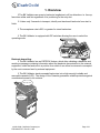
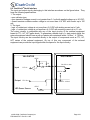
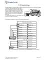
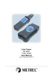
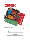
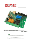
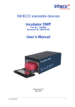
ST-07 Series Bill Validators Operation Manual 1998-1999 CashCode Co. Inc. PT# MAN-ST07 Rev.B2 11/99 Contents Page 1. Overview …………………………………………………….……………………………… 3 2. Main Parts ………………………………………………………..…………..................… 4 3. Precautions …………………….……………..…………………………......................…. 5 4. Banknote Stacking ………….…………………………………...………………………… 5 5. Banknote Jam ..................... ..…………………………………………………………….. 6 6. Maintenance ..................…...……………………………………...………………………. 6 7. Mounting ..................……………..………………………………...……………………… 7 9. Input And Output Circuitry ………..…………………………………..……………...…… 8 10. Harness Connection ……..……………………………………..…………….………….. 10 11. Connector Pinout …………………………………………………………………..……. 11 12. DIP Switch Settings…………………………………………………………....………….. 12 1998-1999 CashCode Company Inc PT# MAN-ST07 Rev.B2 11/99 Page 2/12 1. Overview 5The Bill Validator can accept a banknote lengthwise in all four directions i.e. face up, face down either end first regardless of its positioning in the entry slot. 5 It takes only 2 seconds to transport, identify and stack each banknote from start to finish. 5 The acceptance rate is 95% or greater for street banknotes. 5 The Bill Validator is equipped with DIP switches allowing the user to select the operating mode. O pe n C o ver S w itch es Banknote depositing. 5 The Bill Validator has an ESCROW feature, which after validating a banknote and sending a message containing information about the banknote denomination to the external equipment, holds the banknote in a position from which it can either be returned or accepted by the next command sent by external equipment. 5 The Bill Validator stacks accepted banknotes into a high security lockable and removable cassette (LRC). The design of the Cassette guarantees reliable protection against unauthorised access to its contents. S ecurity Lock C assete Lock (optional) 1998-1999 CashCode Company Inc PT# MAN-ST07 Rev.B2 11/99 Page 3/12 2. Main Parts The Bill Validator consists of the Bill Validator itself and the Cassette. There are Cassettes of different capacities: for 170, 400, 600 and 1000 banknotes. There are two LED indicators on the front panel of the Bill Validator. The first indicator is green and triangular, the second indicator is red and rectangular. When the Bill Validator is in standby mode and ready to accept a banknote, the green triangular indicator is ON. The red rectangular indicator is ON if the Bill Validator can not accept a banknote for some reason (the previous banknote is still being processed, or the acceptance is prohibited by the external equipment, or the Cassette is full, or in case of any malfunction). There are connectors on the side of the Bill Validator to connect it to the external equipment. il B a c 's D E L e t o p e c A r F Re x lB b a v o m Bo h C tc a C x wo o u P &e Ifa trls c e n d t c h e s a n o C r® to c If a d n e c B ill A cce pto r F ace LE D 's R em ovable B ox B ox C atch P ow er & Iso la ted P ulse Inte rface C on nector C a sh C od e ® In te rfa ce C o n n e cto r 1998-1999 CashCode Company Inc PT# MAN-ST07 Rev.B2 11/99 Page 4/12 3. Precautions 1. Badly ripped, wrinkled, or wet banknotes may get jammed in the Bill Validator. 2. The electronic components should not be allowed to get wet at any time. 3. A lot of dust entering the inside of the Bill Validator may interfere with the optical sensors as well as the transport mechanism. 4. Banknote Stacking Accepted banknotes are stacked in the removable Cassettes. Depending on the position of DIP switch SW1-5, the Bill Validator can accept banknotes either one way or four ways. Accordingly, the banknotes in the Cassette take either identical positions or all possible random positions. Various models of the Cassettes allow for different capacities and also different security features. To take the banknotes out of the Cassette, perform the following: 1. Remove the Cassette from the Bill Validator by pressing with your fingers against both Cassette catches, while rotating the cassette at an angle of 15...20 degrees around the axis via which the cassette is hooked to the Bill Validator. 2 1 2. Move the Cassette along the hooking slots in the base of the Bill Validator until the axis is free. 3. Take the Cassette off the Bill Validator by moving it out along the slots in the Bill Validator. 1 3 1998-1999 CashCode Company Inc PT# MAN-ST07 Rev.B2 11/99 Page 5/12 5. Banknote Jam To remove a jammed banknote from the Bill Validator, perform the following: 1. Remove the Cassette carefully, trying not to damage the jammed banknote. 2. Open the two covers of the banknote pathway. 3. Remove the jammed banknote. 6. Maintenance Dirt in the pathway, optical sensors, or magnetic head may affect the acceptance rate of the Bill Validator or even cause jams. To clean the pathway, do as prescribed below: 1. Remove the cassette from the bill validator 2. Open the two covers of the banknote pathway "clam shell". 3. Use a soft cloth moisten with mild, non-abrasive detergent to remove the dirt. Note: Bill validators should be cleaned as needed to maintain optimal performance. This will very depending on location and number of bills inserted. DO NOT USE STRONG THINNERS LIKE ACETONE OR GASOLINE AS IT MAY CAUSE DAMAGE TO PLASTIC PARTS OF THE BILL VALIDATOR. 1998-1999 CashCode Company Inc PT# MAN-ST07 Rev.B2 11/99 Page 6/12 7. Mounting The overall and mounting dimensions are given below. They differ for Cassettes of different capacities. 1 96 (7.7 2 ") 1 00 0 B ills 1 44 (5.6 7 ") 6 00 B ills 11 8 (4 .6 5") 4 00 B ills 8 6 (3 .39 ") 1 70 B ills 1 05 ,4 (4 .1 5") 5 ,5 (0 .2 2 ") 5 0,8 (2") 8 5,5 (3.3 7 ") 9 3 (3 .66 ") 3 2(1 .26 ") 8 6,7 (3.4 1 ") 8 ,25 (.3 2 5 ") The figure «Layout Of Mounting Holes» shows the template for panel of the external equipment where the Bill Validator is to be mounted. All the dimensions are in millimetres and inches (in parenthesis). 1998-1999 CashCode Company Inc PT# MAN-ST07 Rev.B2 11/99 Page 7/12 8. Input and Output Circuitry The Bill Validator has two types of input / output circuitry according to the existing interfaces: isolated low voltage circuitry and TTL/CMOS-level non-isolated circuitry. 8.1. Isolated Pulse Interface The input and output circuitry belonging to this interface are shown in the figure below. They have the following specifications: 1. Isolated OUTPUT PULSE circuitry: - normally open (NO) relay bounce free contact with optocouple electrical insulation; - open circuit leakage current is not greater than 0.1 mA with applied voltage up to 50 VDC; - resistance of the closed contacts is not greater than 100 Ohm; - maximum load current is not more than 70 mA. 2. INHIBIT LINE input: - electrically insulated optocouple input; - input voltage to prohibit any banknote acceptance is not more than +0.5 VDC; - input voltage to allow banknote acceptance is within the range: +3..+24 VDC with the current not exceeding 24 mA. The additional non-isolated TTL-level CREDIT PULSE output has exactly the same circuitry as VALIDATO R EQ U IPM ENT 1K In h ib it L in e (In p u t) + Inh ib it Line (W h ite) V in = 3...2 4V D C - In hib it Line (B row n ) P ulse O utp ut 1 (G re en ) Isola te d P ulse (O u tp ut) U Vo l= 50 V m ax A C /D C Io l= 25 0m A m a x P ulse O utp ut 2 (B lu e) ® output circuitry of the CashCode Serial Interface (see unit 8.2) 1998-1999 CashCode Company Inc PT# MAN-ST07 Rev.B2 11/99 Page 8/12 ® 8.2. CashCode Serial Interface The input and output circuitry belonging to this interface are shown on the figure below. They have the following specifications: 1. The output: - open collector type - open transistor leakage current is not greater than 0.1 mA with applied voltage up to 20 VDC; - closed transistor collector-emitter voltage is not more than +0.6 VDC with current up to 100 mA. 2. The input: - logic «0» state input voltage is not more than +0.5 VDC with sinking current up to 5 mA; - logic «1» state input voltage is not less than +4.5 VDC with sourcing current up to 0.1 mA. The output circuitry is compatible with any of the input circuitry of the external equipment based on TTL, HC, HCT gates levels. To guarantee a reliable logic «1» state output signal, the external equipment should have a pull-up resistor with resistance within 1 kOhm… 4.7 kOhm. The input circuitry can be connected directly to the output of components such as TTL, HC, HCT series of the external equipment. On top of this, any component of the external equipment can provide the input signal within the specs for the input circuitry. VALIDATO R EQUIPM ENT + 5 vD C 4 .7K Input 1K Vo l= 0 .8 v or le ss 4 .7K C P U In + 2 0V D C m a x O utput CPU O ut Io l= 2m A ...10 0m A + 5 vD C LED Pow er Source 2 00 o hm 1998-1999 CashCode Company Inc PT# MAN-ST07 Rev.B2 11/99 Page 9/12 9. Harness Connection ® 1. When used in the external equipment supporting the CashCode Serial Interface or Mars Serial Interface which is compatible with it, the Bill Validator must be connected with both the 6 Pin Power Harness PT# AMZ-XXX-12-06 and the 18 Pin Serial Harness PT# AMZXXX-PC-18. E xte rn al H a rn e ss (C a sh C o de ® S e ria l Inte rfac e ) P o w e r C o n n e cto r: M o le x 1 5 -0 4 -5 0 6 4 & M o le x 5 0 -5 7 -9 3 0 3 , 2 p c. & M o le x 1 6 -0 2 -0 0 9 6 , 6 p c. W ire S ize 2 4 -3 0 AW G P o w e r C o n n e c to r ® C a sh C o d e S e ria l 2. When used in the external equipment In te rfa ce C o n n e c to r In te rfa ce C o n n e c to r: A M P 1 0 2 3 9 8 -7 & supporting Isolated Pulse Interface, the A M P 1 0 2 6 8 1 -4 & Bill Validator is to be connected with the A M P 1 0 2 5 3 6 -7 W ire S ize 2 6 -2 2 AW G 6 Pin Power Harness PT# AMZ-XXX-1206; and the Jumper Connector PT# AMZXXX-PUL-18 may be applied to the 18 pin interface connector of the Bill Validator if required. E xte rn a l H a rn es s (Iso late d P ulse In te rfa ce ) P o w e r C o n n e cto r: M o le x 1 5 -0 4 -5 0 6 4 & M o le x 5 0 -5 7 -9 3 0 3 , 2 p c . & M o le x 1 6 -0 2 -0 0 9 6 , 6 p c . W ire S ize 2 4 -3 0 AW G In te rfa ce P lu g : A M P 1 0 2 3 9 8 -7 & A M P 1 0 2 6 8 1 -4 & A M P 1 0 2 5 3 6 -7 . W ire Ju m p e r, p in 1 - p in 4 1998-1999 CashCode Company Inc PT# MAN-ST07 Rev.B2 11/99 P o w e r & Iso la te d P u lse In te rfa ce C o n n e cto r C a sh C o d e ® S e ria l In te rfa ce C o n n e c to r Page 10/12 10. Connector Pinout Power & Isolated Pulse Interface Connector 1 8-p in C ashC od e ® S erial Inte rfa ce C onn ector 5 6 6-pin P ow e r & Isola ted P ulse Inte rfa ce C o nn ector 1 9 5 1 10 18 6 2 Mating Connector: Molex, Part #:15-04-5064, 1 psc; 50-57-9303, 2 psc; 1 16-02-0096, 6 psc. 2 Terminal 1 2 3 4 5 6 Signal Power Supply (+) Power Supply (-) Output Pulse 1 Output Pulse 2 + Inhibit Line - Inhibit Line Function + 12 V DC Power Ground Pulse Signal Pulse Signal Enable/Disable Accept Bill Wire Colour Yellow Black Blue Green White Brown CachCode® Serial Interface Connector 1 9 10 18 Terminal 1 2 3 4 5 6 7 8 9 10 11 12 13 14 15 16 17 18 Mating Connector: AMP, Part #:102398-7, 1 psc; 102536-7, 1 psc; 102681-4, 1 psc. Signal Credit Pulse Interrupt Serial/Pulse Select Ground Serial Data Output Not connected Not connected Not connected Not connected Out of Service Not connected Accept Enable LED Power Source Send Not connected Not connected Not connected Not connected 1998-1999 CashCode Company Inc PT# MAN-ST07 Rev.B2 11/99 Function Output Output Activity Low Low High/Low Signal Ground ----------------------------------------Output ----------Input Output Input ----------------------------------------- Low Low Low Low Page 11/12 11. DIP Switch Settings The Bill Validator is equipped with an eight position DIP switch and four position DIP switch (optional). These switches allow the user to select an operating mode of the Bill Validator. They are located at the back side of the Bill D IP S w itche s Validator under the cover protecting the CPU (un d e r co ve r) board. They can be reached through special SW 1 openings in the cover only if the Cassette is SW 2 removed. To change the position of a DIP switch, use the point of a sharp instrument. 1 2 3 4 5 6 7 8 O P E N 1 2 3 4 O P E N Each switch is assigned to control the settings shown below. S W 1 S w itch D e scrip tion 1 2 1 2 - 1 p ulse / $1 1 2 - 2 p ulse / $1 1 - 3 p ulse / $1 3 - 4 p ulse / $1 3 - $1 E n able - $1 D isab le 4 4 - $5 E n able - $5 D isab le 5 5 - O ne W ay - F ou r W ay 6 6 - S tacke r U p 7 1 2 3 4 5 6 7 8 2 - S tacke r D ow n - S low P u lse 50 m S O N /30 0m S O F F 8 7 - F ast P ulse 50 m S O N /50 m S O F F 8 - Isolated P ulse Inte rfa ce - A ll Inte rface s O PEN S W 2 S w itch D e scrip tion SW 1 1 1 - $5 0 E nab le 2 - $5 0 D isa ble 2 - $1 00 E na ble 3 - $1 00 D isable 3 - H igh S ecurity 1 2 3 4 4 4 - R eserved O PEN - H igh A cce pt - R eserved SW 2 * This is an example only - please check your USER MANUAL for your model. 1998-1999 CashCode Company Inc PT# MAN-ST07 Rev.B2 11/99 Page 12/12