1
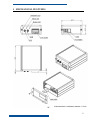
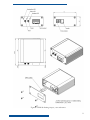
FM4100
USER MANUAL
V1.4
Table of Contents
ATTENTION!.................................................................................................................................... 2
INSTRUCTIONS OF SAFETY ........................................................................................................ 3
LEGAL NOTICE............................................................................................................................... 4
Short description ................................................................................................................................ 5
1.1
About the document....................................................................................................... 5
1.2
Acronyms....................................................................................................................... 5
1.3
Mounting guidelines ...................................................................................................... 5
2
Package contents........................................................................................................................ 6
3
Main Features............................................................................................................................. 7
4
Mechanical features ................................................................................................................... 8
5
6
4.1
Navigation LED ............................................................................................................... 10
4.2
Modem LED .................................................................................................................... 11
4.3
Status LED ....................................................................................................................... 11
Connection & pinout................................................................................................................ 12
5.1
Socket 2×10 ..................................................................................................................... 12
5.2
PORT 1/NMEA ............................................................................................................... 13
5.3
Audio port ........................................................................................................................ 13
5.4
1-Wire® devices .............................................................................................................. 14
ACCESSORIES....................................................................................................................... 15
6.1
Temperature sensor TTJ-101 ........................................................................................... 15
Technical support............................................................................................................................. 17
7
Changes Log Sheet .................................................................................................................. 18
1
ATTENTION!
Do not disassemble the device. Do not touch before unplugging
the power supply if the device is damaged, the power supply
cables are not isolated or the isolation is damaged.
All wireless data transferring devices produce interference that
may affect other devices witch are placed nearby.
The device may be connected only by qualified individuals.
The device must be firmly fastened in the predefined location.
The programming must be performed using a second class PC
(with autonomic power supply).
The device is susceptible to water and humidity.
Warning!! May explode, if a wrong accumulator is used.
Any installation and/or handling during a lightning storm is
prohibited.
2
INSTRUCTIONS OF SAFETY
This chapter contains information on how to operate “FM4100” safely. BY following these
requirements and recommendations you will avoid dangerous situations. You must read these
instructions carefully and follow the strictly before operating the device!
The device uses a 10V...30V DC power supply. The nominal voltage is 24V DC. The allowed
range of voltage is 10V...30V DC, power – not more than 12 W.
To avoid mechanical damage, it is advised to transport the FM4100 device in an impact-proof
package. Before usage, the device should be placed so that its LED indicators are visible, which show
what status of operation the device is in.
When connecting the connection (2x10) cables to the vehicle, the appropriate jumpers of the
power supply of the vehicle should be disconnected.
Before dismounting the device from the vehicle, the (2x10) connection must be disconnected.
The device is designed to mount in a zone of limited access, which is
inaccessible for the operator. All related devices must meet the requirements of standard EN 60950-1.
The device FM4100 is not designed as a navigational device for boats.
3
LEGAL NOTICE
Copyright © 2007 Teltonika
All rights reserved. Reproduction, transfer, distribution or storage of part or all of the contents in
this document in any form without the prior written permission of Teltonika is prohibited.
1-Wire is a registered trademark of Dallas Semiconductor.
Other products and company names mentioned herein may be trademarks or trade names of their
respective owners.
4
SHORT DESCRIPTION
FM4100 is a terminal with GPS and GSM connectivity, which is able to determine the object’s
coordinates and transfer them via the GSM network. This device is perfectly suitable for applications
where location acquirement of remote objects is needed. It is important to mention that FM4100 has
additional inputs and outputs, which let you control and monitor other devices on remote objects. 1Wire® interface (for Dallas digital thermometer or I-Button reader) and CAN interface integrated (for
trucks FMS interface data acquisition). It also has a RS232 port for NMEA output and configuration
(also it could be used for peripheral devices communication with special firmware).
1.1
About the document
This document contains information about the architecture, possibilities, mechanical
characteristics of the FM4100 device.
1.2
Acronyms
PC – Personal Computer.
GPRS – General Packet Radio Service.
GPS – Global Positioning System.
GSM – Global System for Mobile Communications.
SMS – Short Message Service.
AC/DC – Alternating Current/Direct Current.
1.3
Mounting guidelines
The device is mounted in the predefined location in the object by attaching it using a two-
sided tape and additionally securing using three plastic 300x4 mm straps. If there is no possibility of
mounting the device in the predefined location as written above, alternative mounting methods may
be applied, securing the stable position of the device.
5
2 PACKAGE CONTENTS
The FM4100 device is supplied to the customer in a cardboard box containing all the equipment
that is necessary for operation. The package contains:
1. The FM4100 device.
2. Input and output power supply cable with a 2x10 connection.
3. GPS and GSM antennas.
4. Port ½ and Port 3 cables
Supplements:
1. Temperature sensor TTJ-101 (by order).
Note: the manufacturer does not supply a SIM card in the package, which is necessary for connection to the GSM
network! SIM card can be obtained from Your local GSM service provider!
If any of the components is not in the package, please contact the manufacturer’s representative
or the vendor. (www.teltonika.lt)
6
3 MAIN FEATURES
Track your remote objects (trucks, cars) quickly and easily.
The device supports the following GSM bearers:
o GPRS class 10 (up to 44,8 kbps).
o SMS (text/data).
Quad-band:
o European (and Asian) - 900 MHz / 1800 MHz and American - 850 MHz / 1900 MHz.
The aluminum case of the device is very robust and perfectly suitable for installation into harsh
environment such as cars, trucks or other moving objects.
On demand internal rechargeable battery with charge controller.
FM4100 has 4 digital inputs, 4 digital outputs and 4 analogue inputs, which could be used for
performing of various tasks on remote objects, such as monitoring fuel tank level, engine status,
or controlling truck door etc.
FM4100 has 1-Wire® I/O protocol integrated for temperature measuring or key identification.
FM4100 has CAN bus interface that could be used for data acquisition from truck’s FMS
interface.
FM4100 has NMEA output via RS232 that could be used for navigation purposes.
3 LED indicators: “Modem”, “Status” and “Navigate”.
An advanced solution for a very reasonable price.
7
4 MECHANICAL FEATURES
OR
8
Figure 1. FM4100 drawing & spec , two enclosures
9
Part name
Navigation LED
STATUS LED
MODEM LED
GSM
GPS
Socket 2×10
SIM
PORT
1/NMEA
AUDIO
4.1
Physical specification
LED
LED
LED
GSM antenna connector SMA
GPS antenna connector SMA
Tyco Multi-Lock I/O MK-II C175975
GSM SIM card socket
RJ45 8 pin socket
RJ11 4 pin socket
Technical details
Power supply 10...30 V DC
12W Max
Energy consumption:
GPRS:
250 mA r.m.s Max.,
Nominal:
110 mA r.m.s..
Operation temperature:
-25°C ... +55°C
Storage temperature:
-40°C ... +70°C
Relative humidity 5 ... 95%
Navigation LED
When GPS signal is not received, the Navigation LED is blinking as follows:
When GPS signal is received, the Navigation LED is blinking as follows:
When Navigation LED is off, that means a short circuit is GPS antenna or connector.
10
4.2
Modem LED
When device is connected to the GPRS – Modem LED is blinking every second:
When device is not connected to GPRS – Modem LED is blinking every 5 seconds.
4.3
Status LED
When device has uploaded firmware – Status LED should blink. If LED does not blink – it means
that device does not function.
11
5 CONNECTION & PINOUT
5.1
Socket 2×10
ACCUM 2
ACCUM 1
“1-Wire®” DATA
CAN LOW
CAN HIGH
OUT 4
OUT 3
OUT 2
OUT 1
VCC (10÷30)V DC (+)
10
9
8
7
6
5
4
3
2
1
20
19
18
17
16
15
14
13
12
11
“1-Wire®” PWR (+3,3 V)
DIN 4
DIN 3
DIN 2
DIN 1
AIN 4
AIN 3
AIN 2
AIN 1
GND(VCC(10÷30)V DC)(-)
Figure 2. 2×10 socket pinout
Pin
Nr.
Pin Name
1
2
1
VCC (10÷30)V DC
(+)
2
OUT 1
3
OUT 2
4
OUT 3
5
OUT 4
6
7
8
CAN HIGH
CAN LOW
“1-Wire®” DATA
9
ACCUM 1
10
ACCUM 2
11
GND(VCC(10÷30)V
Description
3
Power supply for module. Power supply range (10...30) V DC
Energy consumption: GPRS:
400 mA r.m.s Max., Nominal:
100 mA r.m.s..
Digital output. Channel 1. Open collector output. Max.
500mA.
Digital output. Channel 2. Open collector output. Max.
500mA.
Digital output. Channel 3. Open collector output. Max.
500mA.
Digital output. Channel 4. Open collector output. Max.
500mA.
SAE J1939 CAN interface High channel
SAE J1939 CAN interface Low channel
Data channel for Dallas 1-Wire® devices
This pin is used connected with pin ACUM 2. Function of those
pins is to disconnect the internal accumulator during shipment or
storage. When ACUM 1 and ACUM 2 are connected, the internal
accumulator is on, while disconnected - the internal accumulator is
off.
This pin is used connected with pin ACUM 1. Function of those
pins is to disconnect the internal accumulator during shipment or
storage. When ACUM 1 and ACUM 2 are connected, the internal
accumulator is on, while disconnected - the internal accumulator is
off.
Ground pin. (10÷30)V DC ( - )
12
DC)(-)
12
13
14
15
16
17
18
19
20
5.2
Analog input, channel 1. Input range: 0-10V DC
Analog input, channel 2. Input range: 0-10V DC
Analog input, channel 3. Input range: 0-10V DC.
Analog input, channel 4. Input range: 0-10V DC
Digital input, channel 1
Digital input, channel 2
Digital input, channel 3
Digital input, channel 4
AIN 1
AIN 2
AIN 3
AIN 4
DIN 1
DIN 2
DIN 3
DIN 4
“1-Wire®” PWR
(+3,3 V)
+ 3,3 V output for Dallas 1-Wire® devices. (max 20mA)
PORT 1/NMEA
RJ-45 socket
8 7654321
PORT 1
Pin
Nr.
1
2
3
4
5
6
7
8
Description
GPS_IN (Sirf In)
TX_GPS (NMEA)
GND
RX
TX
CTS
RTS
This port can be used as system port (to flash firmware and configuration to device) with cable
“Port1/2” and as GPS NMEA 0183 output with cable “Port 3”.
5.3
Audio port
RJ-11 socket
1 2 3 4
AUDIO PORT
Pin
Nr.
Description
1
Mic_Signal
2
Speaker_Out_2
3
Speaker_Out_1
4
Mic_GND
13
5.4
1-Wire® devices
One of the FM4100 features is realized 1-Wire data protocol, which enables connection of
thermometer (DS1820, DS18S20 and DS18B20) and I-Buttons DS1990A reading.
FM3101 module
Socket 2×10
GND
GND
DATA
1-Wire data
+5V
+5V OUT
DQ
V DD
Digital
thermometer
(DS1820)
GND
Figure 5. Digital thermometer DS1820 connection scheme
FM3101 module
Socket 2×10
GND
1-Wire data
GND
DATA
DQ
I-Button
DS1990A
GND
Figure 6. Digital key “I-Button” DS1990A connection scheme
14
6 ACCESSORIES
JSC Teltonika offers accessories.
6.1
Temperature sensor TTJ-101
To simplify the mounting of the thermometer in the object, it is placed on PCB and inserted into
the box. Integrator of the system should solder the FM4100 wires to PCB and place the sensor
wherever he wants to measure the temperature.
Dimensions in millimeters, tolerance ±1mm
Figure 11. TTJ-101 dimensions & spec.
In TTJ-100, Dallas digital thermometer DS1820 is used. It is possible to connect up to five
thermometers parallel and measure the temperature in 5 places in the object (see chapter 6.1.1). The
picture bellow describes pinout of the TTJ-100.
15
Left row of pins
Connected
through 100 Ohm
1
to 1 on right row
(FM4100 - 9 pin)
Data (to 1-Wire®
2
Dallas)
(FM4100 - 8 pin)
GND
3
(FM4100 - 7 pin)
Connected to 4
4
on right row.
J1
1
2
J3
3
4
Right row of pins
U1
J2
1
2
1
Vpp (+5 Volts DC)
2
Connected to pin 4
on left row
16
TECHNICAL SUPPORT
If you encounter any problems when using our products, please contact our technical support by
writing an e-mail to [email protected] . We will be pleased to help you.
If you are interested in other products from Teltonika, please visit our website www.teltonika.com,
where you will find our newest products.
If you are interested in product pricing or want to order our products with different antennas,
connectors or built-in programs, please contact our sales department by writing an e-mail to
[email protected]
The supervision of the device is undemanding.
17
7 CHANGES LOG SHEET
Nr.
Date
1
2007 JULY 17
New
version
number
1.1
2
2007 OCTOBER 03
1.2
3
2007 NOVEMBER 05
1.3
4
2007 DECEMBER 13
1.4
Comments
Chapter 4 updated (LED blinking).
Fixed pinout in chapter 5.1
Changed 20’th Pin description in chapter 5.1;
Fixed pinout in chapter 5.3.
Updated chapter 4, second enclosure drawing
added.
18