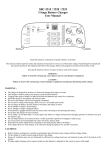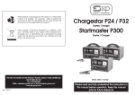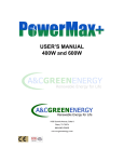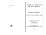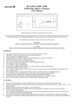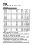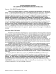
1
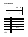
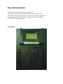
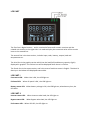
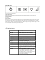
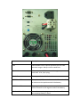
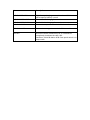
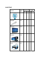
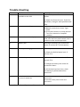
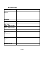
Sine Wave Solar UPS Owner’s Manual KSU 1024S, KSU 2048S Thank you for choosing the intelligent NON STOP Solar UPS with state of art technology. Please read this guide carefully before installing the product. Should you have any queries & suggestions please call on us. We will be happy to provide the assistance that you are looking for. We wish you years of joyful homemaking with the NON STOP UPS & look forward to a great association with you. Contents 1. Overview……………………………………………………….. 2. Applications…………………………………………………… 3. Key features………………………………………………….. 4. Technical Specifications………………………………… 5. Physical Description………………………………………. 6. Safety Instructions………………………………………… 7. Installation………………………………………………….. 8. Load Chart…………………………………………………… 9 . Trouble Shooting…………………………………………. 10. Error Messages…………………………………………… Warranty card……………………………………………. 11. 4 4 5 6 8 12 13 14 15 16 17 Over view A UPS is an electrical apparatus which is interfaced between the electric network and the appliances that need to be protected from power uncertainties like power outages, over voltages, under voltages, power line disturbances and surges. The UPS have the battery source which gets charged when the mains power is available and provides the back up power from the battery when the mains is not available, ensuring uninterruptible power supply. The intelligent Sine wave Solar UPS with state of the art technology provides following key functionalities: When the solar power and mains power are available, battery will be charged by solar panel. If the battery voltage is too low, then it will also charge the battery through mains power. When the mains power and solar power are available, the load will be powered by Solar power. If the load requirement is more than the available solar power then the battery will supply the additional load. When solar power is not available , the grid power will charge the battery & supply the load like any conventional UPS. It is compact & lighter than any other UPS in its class. Applications Power back up for your home Domestic computer and its peripherals Emergency power systems Photography Small water pumps and all motor based small applications Television, Fans & Tube‐lights Professional applications where waveform is critical Key Features MCU control guarantees high reliability Pure Sine wave output Compact and light weight Simple & easy installation High efficiency & longer back up time Intelligent charging ensuring more battery life Normal & Computer mode operation of the UPS 10% more solar energy is harvested by using MPPT solar charger Auto priority logic to charger from both mains & solar simultaneously. No load sleep: If the load is less than 20W, the inverter will go to automatic sleep and save power Auto wakeup : Inverter will switch on automatically when the battery is charged by solar to predetermined level. Phase reversal protection Overload protection & auto recovery Short circuit protection Liquid crystal display for UPS status monitoring Technical Specification Mains Input Model KSU 1024S+ KSU 2048S+ 230V AC, 50 Hz Nominal input : Input voltage lower cut off o Computer mode : 175 V AC o Normal mode : 125 V AC Input voltage higher cut off : 270 V AC (configurable) Input connection : 3 pin plug (15A) Output Model Inverter Mode Out put voltage (VAC) Out put power (VA/Watt) Out put frequency (Hz) Out put voltage wave form Out put connection Efficiency ( %) Mains Mode Out put voltage (VAC) Efficiency ( %) Transfer time LCD indication Audible Alarm Nose Level Battery voltage (V) Battery capacity ‐ Recommended (AH) Typical Low battery Alarm Voltage (V) Typical Shut down battery voltage (V) NS 1024S+ NS 2048S+ : : 1000/1000 : : : : : : : : 208‐230 2000/2000 49.0 – 51.0 Pure Sine wave 6A outlet 80% 15A outlet 82% Same as input >96% <10 milliseconds Status of UPS/Solar charger, Solar generated power Battery low Mode changeover : <50 dB : 24 48 : 300X2 300X4 : 22.0 44.0 : 21.6 43.2 MPPT Solar charger (Intelligent maximum power point tracking (MPPT) technology) Model Battery charging current (A) Maximum solar input power(W) Peak charger efficiency Max Solar open circuit voltage (V) NS 1024S+ : 40 NS 2048S+ 40 : 1000 2000 : : 98% 85 120 Protection Lightening, battery over voltage, battery under voltage, battery wire removal, out put short circuit, over load, phase reversal. Physical 1024S+ Dimension : 355×144×215 mm Net weight: 6.5Kg. 2048s+ Dimension : 478×191×339 mm Net weight: 16Kg. Environment Humidity : 0‐ 90 % RH Operating temperature: 0‐45 ºC Note: Specifications are subject to change without prior notice. Physical Description Below Figure shows the 3D view of the Solar UPS. The product has the metallic enclosure. Adequate cooling fans are provided for thermal management. Front panel has a LCD to indicate the instantaneous status of the product. Front panel switch is provided to select different operating modes. Front panel LCD PART The first line is digital section,and is consisted of two small numeric sections and the related unit section on the right side. It is used to display the numerical value of the certain item on the second line. The second line is the item section, includes input, solar, battery, output, load and temperature etc. The third line is the graphic section which has the load (left) and battery capacity (right) displayed in graphics. The failure icon will be displayed when there is a failure. The fourth line is the status section, and is the area of machine status in English. The detail is descript in the below LCD displayed status table. LED PART I Line status LED: When Line is OK ,the LED light on. PV Panel LED: When PV panel is OK , the LED light on. Battery status LED:When battery voltage is OK, the LED light on, when battery low ,the LED blink. LED PART II Inverter status LED: When Inverter takes load, the LED light on. Bypass status LED: When Bypass takes load, the LED light on. Fault status LED:When UPS fail, the LED light on. BUTTON PART Button function description Power On button When there is only battery connected, press this button to power on the solar UPS. Function button Not used. Query button Short press,it will in turn shows the items in the second row of display. Long press, it goes to rotational shows and the items will alternately show every 2s and the turns are: “Input, Solar, Battery, Output, Load and Temperature”. When long pressing the button again, it will turns to display output and PV generated power. LCD displayed status : Information on LCD MNS ON MNS OFF MPPT ON MPPT OFF MPPT FLT INV ON UPS BPS CHG ON CHG OFF UPS OFF UPS FAIL LOAD HI Meaning Power supply from mains is available. Power supply from mains is not available. Solar power is available Solar power is not available MPPT charger is not functioning The Inverter is functioning. The Inverter is OFF, load is take by mains Battery is getting charged by mains. Battery is not getting charged by mains. UPS is in sleep mode and not goes to Inverter mode during mains power is off. UPS is not working. LCD displays an error code . UPS is over loaded. It restarts for 6 times with an alarm. If the load is reduced with in this period it will restore normal functioning. Else, It will shut down with a trip message to protect itself from continuous overloading. Information on LCD OP SHORT Meaning UPS output is short circuited. It will shut down with a trip message to protect itself from short circuit. Switch: Computer mode Sleep mode Normal mode The functions of each mode are given below : Switch position Top (=) Type of mode Computer mode Middle(o) Sleep mode Bottom (‐) Normal mode Rear panel Description UPS switches to Inverter mode when the mains voltage goes below 175 V and above 270V. Mains ON : UPS is in bypass mode & battery will be charging. Mains OFF : UPS will be idle and battery will be charging by Solar. UPS switches to Inverter mode when the mains voltage goes below 125 V and above 270 V Name FUSE AC MAINS UPS OUT BATTERY – POS BATTERY – NEG BAT CHARGE‐ NORM Description Connected at mains input & protects the UPS from electrical surges. Always use the rated fuse. Mains input to UPS. Connected through the power cord with 15 A, 3 pin plug. The output of the UPS for load. The positive (RED) terminal is extended from the UPS to connect to the positive end of the battery. The negative (BLACK) terminal is extended from the UPS to connect to the negative end of the battery. Normal battery charging current. Set when 120 AH or less capacity battery is used. Name BAT CHARGE‐ HIGH BAT CHARGE‐ENABLE BAT CHARGE‐DISABLE SOLAR IN ‐POS SOLAR IN ‐NEG UPS OFF Description High Battery charging current. Set when 150AH or more capacity battery is used. To enable the charging from mains To disable the charging from mains Connection to positive terminal of Solar module. Connection to negative terminal of Solar module. Press this switch momentarily for 2‐3 seconds to completely shutdown the solar UPS . Condition: PV NG & Mains off & front panel switch is in sleep mode. Safety Instructions Always disconnect the battery cables of the UPS only after turning the UPS into sleep mode & disconnecting the UPS from AC mains. Connecting the battery terminals usually create an arc. This is normal. Connect the battery terminals firmly to ensure no loose contacts. Follow battery manufacturer's instructions carefully. Do not allow the UPS to be exposed to flammable liquids, rain, excessive heat or direct sunlight. Connect the UPS to a grounded power outlet. Always use rated fuse. While going out on vacations keep the UPS in sleep mode & Solar module connected to keep the battery in charged condition. Place the UPS in an adequate airflow and dust free area. Maintenance must be performed by a qualified personnel. Failure to do so could result in electric shock. Use tools with insulated handles during installation and maintenance to avoid personnel injury. Installation Package content: Solar UPS ‐ one unit ( with battery cable & Mains cord) Owner's Manual with Warranty card Spare fuses Battery interconnect cable (for more than one battery option) Installation Procedure Turn the front panel switch to sleep mode Connect the positive and negative terminals of the battery to the respective battery cable of the UPS. Connect the positive and negative terminals of the solar panel to the respective terminals of the SOLAR IN located at rear panel. Connect the mains cord of the UPS to 15 A mains outlet. It is recommended that before connecting to the load charge the battery for a minimum period of 8 hours. Plug your peripheral equipment / appliances to "UPS OUT" Turn the front panel switch to Normal mode. Turn it to computer mode if computers are part of the load. Ensure that the connected load is with in the rated limit. Warning!: Ensure that battery connections are made with correct polarity. Ensure that Solar panel connections are made with correct polarity. Ensure that Solar terminals are not shorted while MPPT is ON. Failed to do so may cause damage to UPS. Load Chart NS 1024S+ NS 2048S+ A 6 B 4 A 12 B 8 40W 7 5 13 10 125W 1 0 2 0 150W 1 3 2 6 40W 0 1 1 2 Appliance Typical Load Fan 75W Tube light Television Computer Printer Trouble shooting Sl.No. 1 Problem AC mains not available to the UPS 2 Inverter not working 3 Inverter intermittently trips 4 Battery low 5 Battery not charging 6 Less back up time 7 The solar panel is connected but the LCD shows SOLAR OFF Remedy 1) Check the power from the mains socket. 2) Check the fuse at the rear. If the fuse has blown, change it with specified rated fuse. 1) Battery is low. 2) Battery terminals are loose. Tight them. 3) Front panel switch is in sleep position. Turn it to Normal or Computer position. UPS might be overloaded. Reduce the load, turn the front panel switch, then it resumes to the normal operation. Recharge the battery for minimum 8 hours to restore 90 % of the capacity 1) Battery terminals are loose. 2) Check the distilled water level. If not ok, fill it. 1) Check the distilled water level. If not ok, fill it. 2) Charge the battery with mains for minimum 8 hours. If still the back up time is less, check the battery by authorized service personnel. 1) Check the solar panel to UPS cable Connection. 2) Check the solar panel is clean and uncovered. Note: If the problem still persists call the service centre. Error Messages On rear occasions, you may notice certain error codes on the top right side of LCD. These error codes may be interpreted as below. Shut down the UPS immediately & call the service centre. Error code Meaning 04 Internal temperature of UPS is very high. 02 Output short. 01 Output overload timeout. 16 Inverter fail. 32 Booster fail. 08 Over Charge. Warranty Card Customer Name: Address: UPS Model: UPS Sl. No. Solar panel (Make , Model & Sl No) Battery (Make , Model & Sl No) Invoice No & Date Dealer’s Name, Address & Contact No. Dealer’s stamp & Signature Manufactured By: The End