1
MultiValent Controller – MVC
КОНТРОЛЛЕР HONEYWELL ДЛЯ СИСТЕМ ТЕПЛОСНАБЖЕНИЯ
ИНСТРУКЦИЯ ПОЛЬЗОВАТЕЛЯ
® U.S. Registered Trademark
Copyright © 2011 Honeywell Inc. • All rights reserved
RU2B-0361GE51 R1011
РУКОВОДСТВО ПОЛЬЗОВАТЕЛЯ
Информация о торговых марках
RU2B-0361GE51 R1011
КОНТРОЛЛЕР MVC
Echelon, LON, LONMARK, LONWORKS, LonBuilder, NodeBuilder, LonManager,
LonTalk, LonUsers, LonPoint, Neuron, 3120, 3150, логотипы Echelon, LONMARK и
LonUsers являются торговыми марками Echelon Corporation
зарегистрированными в США и других странах. LonLink, LonResponse,
LonSupport и LonMaker являются торговыми марками Echelon Corporation.
КОНТРОЛЛЕР MVC
СОДЕРЖАНИЕ
СОДЕРЖАНИЕ
СОДЕРЖАНИЕ .................................................................................................................. 3
СТРУКТУРА РУКОВОДСТВА ........................................................................................... 7
ТЕХНИЧЕСКАЯ ДОКУМЕНТАЦИЯ ................................................................................................................. 7
ОБЩАЯ ИНФОРМАЦИЯ................................................................................................... 9
ФУНКЦИОНИРОВАНИЕ ................................................................................................. 11
ОПИСАНИЕ ИНТЕРФЕЙСА ПОЛЬЗОВАТЕЛЯ ........................................................................................... 11
ПРОЦЕДУРЫ БАЗОВОГО УПРАВЛЕНИЯ................................................................................................... 16
Использование Пароля ......................................................................... 16
Обзор и Редактирование Информации................................................ 21
Выбор Элемента.................................................................................... 23
Настройка и Сохранение Опций и Значений ....................................... 24
Командные Символы............................................................................. 27
ЧАСТЫЕ ОПЕРАЦИИ .................................................................................................................................... 40
Изменение Временных Расписаний ..................................................... 40
Обзор Информации Статуса Компонента Системы............................ 45
Изменение Режима Работы Насоса ..................................................... 46
Обзор Тревог.......................................................................................... 48
Подсчет часов наработки ...................................................................... 49
Запись Тренда........................................................................................ 51
СПЕЦИАЛЬНЫЕ ДЕЙСТВИЯ........................................................................................................................ 54
Правка Точки Данных ............................................................................ 54
Изменение Даты и Времени.................................................................. 56
РАБОЧАЯ ПОСЛЕДОВАТЕЛЬНОСТЬ......................................................................................................... 58
Стартовая Последовательность........................................................... 58
Рабочая Последовательность .............................................................. 59
Сброс контроллера................................................................................ 60
Обзор ...................................................................................................... 61
Меню Домашний экран.......................................................................... 62
Тревоги ................................................................................................... 63
Сервис (Обслуживание) ........................................................................ 64
Наработка............................................................................................... 65
Тренды.................................................................................................... 65
Конфигурирование Интерфейса........................................................... 66
Дата / Время........................................................................................... 67
Расписания............................................................................................. 68
Суточные Расписания ........................................................................... 69
Точки Данных ......................................................................................... 70
Системные Данные................................................................................ 71
ОСНОВНЫЕ ПОЛОЖЕНИЯ............................................................................................ 72
ТОЧКИ ДАННЫХ ............................................................................................................................................ 72
Физические Точки Данных..................................................................... 72
Псевдо Точки Данных............................................................................ 72
Глобальные Точки Данных.................................................................... 73
Mapped Datapoints ................................................................................. 73
АТРИБУТЫ ТОЧЕК ДАННЫХ ....................................................................................................................... 73
Задержка Тревоги .................................................................................. 74
Гистерезис Тревоги ............................................................................... 74
Подавление Тревоги.............................................................................. 75
Статус Тревоги....................................................................................... 76
3
RU2B-0361GE51 R1011
СОДЕРЖАНИЕ
КОНТРОЛЛЕР MVC
Тип Тревоги............................................................................................ 76
Alarm Definition ....................................................................................... 76
Broadcast Hysteresis .............................................................................. 77
Единицы Измерения.............................................................................. 78
High/Low Alarm/Warning Limits .............................................................. 78
Hours Since Serviced.............................................................................. 79
Гистерезис ............................................................................................. 79
Input/Output Status Text ......................................................................... 79
Интервал Подсчета ............................................................................... 79
Интервал Предела ................................................................................ 79
I/O характеристика................................................................................. 80
Pull-Up Resistor Handling ....................................................................... 80
Last Change ............................................................................................ 80
LED Mode ............................................................................................... 81
Maintenance Alarm ................................................................................. 81
Ручное Значение ................................................................................... 81
Normally Open/Normally Closed ............................................................. 82
Время Рабочего Хода............................................................................ 82
Off Phase ................................................................................................ 82
Время Наработки................................................................................... 83
Запись часов наработки........................................................................ 83
Режим Работы ....................................................................................... 83
Тип Выхода ............................................................................................ 85
Point Alarms ............................................................................................ 85
Продолжительность Импульса............................................................. 85
Уровень Доступа для Чтения................................................................ 85
Безопасное Положение / Safety pos. value .......................................... 86
Фактор Масштаба .................................................................................. 87
Точность Датчика .................................................................................. 87
Калибровка Датчика .............................................................................. 88
Subtype ................................................................................................... 88
Suppress Point ........................................................................................ 88
Switching Down....................................................................................... 89
Switch-On Counter .................................................................................. 89
Technical Address................................................................................... 89
Trend Hysteresis ..................................................................................... 89
Запись Тренда ....................................................................................... 90
User Address........................................................................................... 91
Значение ................................................................................................ 91
Уровень Доступа для Записи................................................................ 92
Защита от Записи .................................................................................. 92
Список Атрибутов Точек ....................................................................... 94
РАСПИСАНИЯ (ВРЕМЕННЫЕ ПРОГРАММЫ) ........................................................................................... 96
Структура ............................................................................................... 96
Индивидуальные Расписания............................................................... 97
Создание Расписания ......................................................................... 100
ОБРАБОТКА ТРЕВОГ ................................................................................................................................. 101
Точки в Тревоге ................................................................................... 101
Системные Тревоги ............................................................................. 102
Data Storage ......................................................................................... 105
Alarms Sent across the System Bus ..................................................... 106
КОММУНИКАЦИЯ ........................................................................................................................................ 106
System Bus ........................................................................................... 106
PC Communication ............................................................................... 108
Буфер Тренда ...................................................................................... 108
РЕЖИМ ТЕСТИРОВАНИЯ........................................................................................................................... 108
ОБСЛУЖИВАНИЕ ......................................................................................................... 109
ЗАПУСК КОНТРОЛЛЕРА............................................................................................................................. 109
ПРОВЕРКА ЭЛ. ПОДКЛЮЧЕНИЙ .............................................................................................................. 109
RU2B-0361GE51 R1011
4
КОНТРОЛЛЕР MVC
СОДЕРЖАНИЕ
СБРОС КОНТРОЛЛЕРА .............................................................................................................................. 109
УСТРАНЕНИЕ НЕИСПРАВНОСТЕЙ........................................................................................................... 110
5
RU2B-0361GE51 R1011
СОДЕРЖАНИЕ
RU2B-0361GE51 R1011
КОНТРОЛЛЕР MVC
6
КОНТРОЛЛЕР MVC
СТРУКТУРА РУКОВОДСТВА
СТРУКТУРА РУКОВОДСТВА
В разделе “Техническая Документация” перечислена имеющаяся
документация на контроллер серии MVC80.
Раздел “Обзор” предлагает краткий обзор по следующей базовой информации:
•
•
•
•
•
•
Общая информация
Точки Данных
Применения
Временные расписания
Управление /Тревогами
Пароли и Уровни Доступа
Раздел “Функционирование” включает подробную информацию:
• Основные Процедуры
Описание интерфейса оператора, основы управления и защита паролем.
• Частые Операции
Описывает наиболее частые операции, такие как изменения в расписаниях
и других.
• Специальные Действия
Объясняет специальные операции, например, правка Точки Данных и
Даты/Время.
• Рабочая Последовательность
Представлен схематичный обзор всех рабочих последовательностей в
контроллере MVC.
Раздел «Основные Положения» объясняет базовые системные положения
контроллера MVC, включая детальную информацию:
•
•
•
•
Точки Данных
Атрибуты Точек
Расписания
Коммуникация
Раздел “Сервис” представлена подробная информация для установщика:
•
•
•
•
•
запуск контроллера
соединения эл. проводов
сброс
сохранение данных
устранение неисправностей
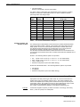
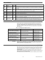
Техническая Документация
Следующие документы содержат дополнительную информацию по
контроллеру MVC.
Номер
Описание
RU0B-0646GE51
MultiValent Controller – MVC8xxx Паспорт Изделия
MU1B-0473GE51
MultiValent Controller – MVC Инструкция по монтажу
MultiValent Controller – MVC Руководство по Применению
7
RU2B-0361GE51 R1011
СТРУКТУРА РУКОВОДСТВА
RU2B-0361GE51 R1011
КОНТРОЛЛЕР MVC
8
КОНТРОЛЛЕР MVC
ОБЩАЯ ИНФОРМАЦИЯ
ОБЩАЯ ИНФОРМАЦИЯ
Общее описание
Описание точек данных
Контроллер MVC (Multi-Valent-Controller) позволяющий реализовать
автоматическое управление для систем теплоснабжения (ИТП, ЦТП):
Точки Данных – базовые понятия контроллера MVC. Точки данных содержат
информацию о таких компонентах системы, как например контур отопления,
который в свою очередь содержит специфическую информацию о системе, как
то: показания датчиков, статус оборудования, предельно допустимые
значения, настройки по умолчания и т.д. Пользователь имеет доступ к
просмотру информации точек данных. Пользователь, имеющий
соответствующий уровень доступа, может изменять те или иные настройки
точек данных.
Пример:
Информацию по температуре наружного воздуха можно посмотреть в точке:
НАРУЖ_ТЕМП
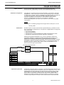
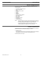
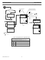
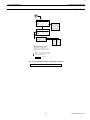
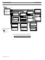
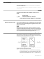
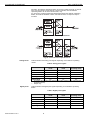
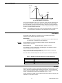
Расписания
В любой момент вы можете использовать расписания для установки того или
иного значения для определенных точек данных. Поддерживаются следующие
типы расписаний:
• Суточная программа
• Недельная программа
• Специальная суточная программа (настройка для праздничных дней)
• Расширенное изменение расписания (функция “СЕГОДНЯ”)
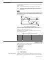
Недельная программа формируется из суточных программ. Недельные
программы формируют годовую программу (автоматически копируясь на
период одного года). В специальной суточной программе назначается
расписание на праздничных дней (например, Новогодние праздники). Функция
“СЕГОДНЯ” позволяет непосредственно влиять на текущее расписание. Эта
функция позволяет изменить какую-либо уставку на ближайшие 24 часа,
исключая влияние других расписаний.
Расписания Специальных дней
выходной
СЕГОДНЯ
Праздники
(Good Friday )
праздник
Годовое
(С …До)
Суточное Расписание
1 .. 20
Mo
Tu
We
Th
Fr
Sa
Su
<within 24h – max. 48h>
Раб.день
Раб.день
Раб.день
Праздник
Раб.день
Выходной
Выходной
НЕДЕЛЬНОЕ
НЕДЕЛЬНОЕ
НЕДЕЛЬНОЕ
.
..
...
1-год-Период (52 недели)
Управление тревогами
Управление тревогами является одной из ступеней обеспечения безопасности
системы. Все тревоги хранятся в файлах и могут быть включены в отчет. Если
конфигурация системы позволяет, вы можете распечатывать список тревог
или выводить его на экран SCADA системы. Контроллер поддерживает две
группы тревог: критические и некритические. Критические тревоги имеют
приоритет над некритическими. Системные тревоги, которые могут вызвать
останов контроллера или системы в целом, всегда являются критическими.
9
RU2B-0361GE51 R1011
ОБЩАЯ ИНФОРМАЦИЯ
КОНТРОЛЛЕР MVC
Следующие события могут вызывать аварийное сообщение:
•
•
•
•
Выход значения точки данных за допустимые границы
Необходимость сервисного обслуживания
События счетчиков
Изменение состояния дискретной точки
Буфер тревог может содержать до 99 тревог.
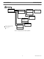
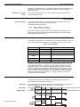
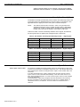
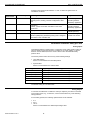
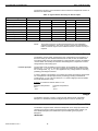
Пароли / Уровни доступа
Система управления защищена паролями. Использование трех уровней
доступа обеспечивает доступ только авторизованного персонала к чтению
и/или правке важных системных данных. Для входа на уровень доступа 1
пароль не требуется, но будут отображаться только экраны, доступные на
данном уровне. Для входа на уровни доступа 2 и 3, должен быть введен
соответствующий пароль.
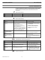
Уровень
доступа
Необходимость
ввода пароля
Особенности функционирования
Пользователи
1
Нет
Отображение информации по Точкам и Тревогам
Пользователь,
например, владелец
Отображение и изменение Расписаний, часов
наработки, трендов, даты / времени и т.д.
2
Да
Отображение как для Уровня 1 и информация по
счетчикам.
Опытный
Пользователь
Отображение и изменение Расписаний, системных
часов и информации по другим контроллерам на той же
шине.
3
Да
Отображение и изменение информации доступной для
пользователей с уровнем доступа 1 и уровнем 2.
Сервисный Инженер
Правка описаний точек, параметров и уставок.
Сброс счетчиков.
4
Да
Отображение и изменение информации доступной для
пользователей с уровнем доступа 1, уровнем 2 и
уровнем 3.
Все элементы (точки, параметры) имеющие уровень
доступа 4 скрыты при просмотре через дисплей
контроллера.
Оператор,
использующий
SCADA
(диспетчерский
терминал)
Защита паролем позволяет избежать доступа неавторизованного
пользователя к важным системным параметрам, изменение которых,
может повлиять на работоспособность системы.
RU2B-0361GE51 R1011
10
MVC CONTROLLER
OVERVIEW
ФУНКЦИОНИРОВАНИЕ
Терминология
Ниже приведена расшифровка терминов, которые используются при описании
функционала контроллера:
Меню и подменю
Меню являются начальным уровнем диалоговых окон контроллера и включают
в себя все компоненты, заложенные программой контроллера.
Списки
Под уровнем меню отображается список элементов, входящих в данное меню
(например, точки, атрибуты точек, расписания).
Пункты
Отдельные пункты могут быть выбраны из списка на экране (пунктом списка
может служить подменю, точка).
Значение
Отображение на экране, например, числового показания датчика с указанием
единицы измерения (например, показание температуры 18 C°).
Опция
Значение опции может быть выбрано из списка вариантов, например, для
группы насосов может быть выбран ВКЛ. (ПУСК) или ВЫКЛ. (СТОП).
Командные символы
Командные символы – это графические символы, появляющиеся в
определенных местах экрана, отвечающие за функциональную
последовательность, например, работу, редактирование, удаление и др.
функции (см. раздел “Командные Символы”).
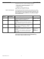
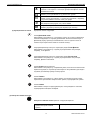
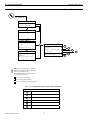
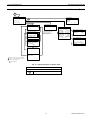
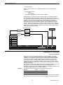
Описание Интерфейса Пользователя
Лицевая панель контроллера содержит следующие элементы:
•
•
•
•
LCD дисплей (1)
6 функциональных клавиш (2)
1 поворотно-нажимная кнопка (3)
6 светодиодов (LED) (4)
3
1
2
1
!
2
C
(1) LCD Дисплей
A1 A2 Tx Rx
4
LCD дисплей поддерживает графический интерфейс отображающий
информация о состоянии системы, вводимые данные и доступные меню. LCD
отображает до 5 строк текста с 20 знаками в каждой строке.
11
RU2B-0361GE51 R1011
ФУНКЦИОНИРОВАНИЕ
КОНТРОЛЛЕР MVC
Подсветка дисплея включается при нажатии любой клавиши или повороте
(нажатии) поворотно-нажимной кнопки. Подсветка отключается после двух
минут бездействия (не нажимается ни одна кнопка, не поворачивается
поворотно-нажимная кнопка).
Меню открываются при нажатии соответствующей функциональной клавиши
(см. раздел “Функциональные клавиши”).
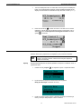
ВАЖНО: Приведенные изображения экранов контроллера являются
примерами и могут отличаться от экрана вашего контроллера.
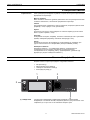
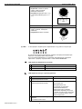
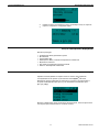
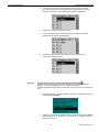
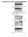
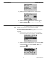
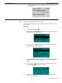
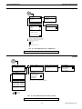
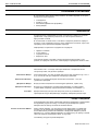
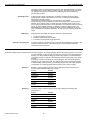
Меню и под-меню
В Главном меню, компоненты контроллера отображаются как под-меню:
Заголовок
Главное меню
Выделенный
пункт
Список выбора
Подменю
Рис. 1. Главное меню и подменю
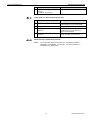
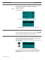
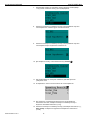
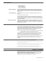
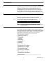
Список пунктов, опций и значений
В под-меню отображается выбранный список элементов, таких как,
температура, статус и т.д. с соответствующим значением или опцией, которую
можно редактировать.
Заголовок
Список элементов
Командный символ
Значение (изм)
Опция (выбор)
Рис. 2. Список элементов, Значение, Опции и Командные символы
ПРИМ.:
Командные Символы
If a string of various length with the asterisk "*” should appear, this means
that currently no value is available.
Специальные командные символы со следующими функциями могут
использовать в определенных местах рабочей последовательности:
Автоматический режим
Точка находится в автоматическом режиме, режим может быть
изменен на ручной режим
Ручной режим
Точка находится в ручном режиме, режим может быть переведен в
автоматический режим
Расписание
Точка управляется расписанием. Расписание может быть
отредактировано в соответствующем разделе
RU2B-0361GE51 R1011
12
КОНТРОЛЛЕР MVC
ФУНКЦИОНИРОВАНИЕ
Exceptional Time Program Override (функция СЕГОДНЯ)
Значение точки задается с помощью функции СЕГОДНЯ в течении
ближайших 24 часов.
Правка
Элемент (точка, расписание и т.д.) может быть удален
Добавить
Элемен (точка, расписание и т.д.) может быть добавлен , например,
точку можно добавить в список точек для тренда
Удалить
Item (datapoint, time program, etc.) can be deleted
Разрешить/Запретить
Элемент разрешен (отмечен) или запрещен (не отмечен)
(2) Функциональные кнопки
Функционал кнопок следующий:
кнопка ДОМАШНИЙ ЭКРАН
Обеспечивает быстрый доступ к стартовому экрану, на котором отображается
основная информация по текущему применению. Автоматический возврат к
Домашнему экрану происходит автоматически, если ни одна из кнопок на
панели контроллера не была нажата в течение 10 минут.
1
2
запрограммирована для быстрого перехода в раздел ТОЧКИ ДАННЫХ
Обеспечивает быстрый доступ к одному из разделов меню контроллера,
например, Точки Данных.
запрограммирована для быстрого перехода в раздел РАСПИСАНИЯ
Обеспечивает быстрый доступ к одному из разделов меню контроллера,
например, Времен. Расписания.
кнопка СЕРВИС (ОБСЛУЖИВАНИЕ)
Обеспечивает быстрый доступ к Сервисному меню, включая пользовательские
сервисные функции, и под-меню для Инженера по обслуживанию. Для входа в
под-меню для Инженера требуется ввод пароля.
!
C
кнопка ТРЕВОГИ
Обеспечивает быстрый доступ к меню Тревог, где находится журнал тревог,
перечислены критические и некритические тревоги, подтвержденные тревоги.
кнопка ОТМЕНА
Обеспечивает возврат на предыдущий экран, отмену введенного значения,
подтверждение сообщения об аварии.
(3) Поворотно-нажимная кнопка
Поворотно-нажимная кнопка работает следующим образом:
Поворот кнопки по часовой
стрелке или против часовой
стрелке:
13
Навигация - Выделение - Настройка
RU2B-0361GE51 R1011
ФУНКЦИОНИРОВАНИЕ
КОНТРОЛЛЕР MVC
• навигация по меню и спискам
• выделение элементов (меню,
списка, опций, значений,
командных символов)
• настройка опций (ON, OFF и т.д.)
и значений (температура в °C, и
т.д.)
-Highest level
Start
Previous
Decrease
any
Нажатие на кнопку:
+
Menus
Lists
Options
Values
Command
Symbols
Lowest level
End
Next
Increase
any
Выбор - Сохранение
• выбор элементов (меню, списка,
опций, значений, командных
символов)
• сохранение опций и значений
Select
Menus
Lists
Options
Values
Command
Symbols
Save
Табл. 1. Функциональность Поворотно-нажимной кнопки
(4) LEDs
6 светодиодных индикаторов отображающих статус работы контроллера.
A1 A2 Tx Rx
В следующем разделе представлено описание светодиодных индикаторов
вместе со статусами работы контроллера.
Для получения информации по устранению неисправностей, пожалуйста
обратитесь к разделу “Функции LEDs” в главе “ОБСЛУЖИВАНИЕ”.
LED индикатор Напряжения (зеленый)
Режим LED
Значение
1
ВКЛ.
Нормальная работа
2
ВЫКЛ.
Напряжение питания не в норме
LED индикатор Статуса / Тревоги (красный)
Режим LED
Значение
1
LED остается выключенным после
подачи напряжения питания
Нормальная работа
2
LED постоянно мигает после
подачи напряжения питания
Проблемы с аппаратной частью
контроллера или
Сбой применения или
В контроллер не загружено
применение вообще или
Оператор вручную остановил
применение, например, используя
XL-Online. В этом случае, LED будет
гореть в течение 20 минут после
подачи напряжения.
3
RU2B-0361GE51 R1011
LED постоянно мигает следующим
образом:
4 x ON/OFF затем пауза
14
Сбой датчика аналогового входа
КОНТРОЛЛЕР MVC
ФУНКЦИОНИРОВАНИЕ
5
Rx , Tx
Значение
LED постоянно мигает следующим
образом:
7 x ON/OFF затем пауза
Сбой коммуникации по Panel Bus
C-Bus Send (Tx) / Receive (Rx) LED (желтый)
C-Bus LED Behavior
Meaning
Оба диода мигают
Нормальная работа, C-bus
функционирует в штатном режиме
2
Оба диода выключены
Нет передачи данных по C-bus
3
Rx диод мигает и Tx диод
выключен
Связь по C-bus отключена, но
контроллер получает данные от
других контроллеров
4
Tx диод мигает и Rx диод
выключен
Контроллер пытается установить
связь по C-Bus, но нет ответа.
1
A2, A1
Режим LED
LED индикаторы Применения (желтый)
ПРИМ.:
Этот LED может быть использован для отображения режима,
например, “Охлаждение”, “Отопление”, “Тех.Обслуживание ” в
зависимости от применения.
15
RU2B-0361GE51 R1011
ФУНКЦИОНИРОВАНИЕ
КОНТРОЛЛЕР MVC
Процедуры Базового Управления
ПРИМ.:
Экраны контроллера, показанные в этом руководстве, являются
примерными и могут отличаться от экранов отображаемых вашим
контроллером MVC.
Использование Пароля
Пароль состоит из 4х значного цифрового кода и позволяет получить доступ к
экранам с важными настройками. This may result in the editing of prior noneditable functions and or the access to additional functions that are not available
before.
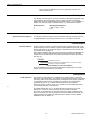
Пароль зависит от уровня доступа следующим образом:
Уровень доступа
Необходимость
ввода пароля
Пароль по
умолчанию
1
Нет
нет
2
Да
2222
3
Да
3333
ВАЖНО
Символ доступа
Если вы забыли пароль, то свяжитесь с вашим местным Парнером
отдела Тепловой Автоматики. Список региональных партнеров на
сайте отдела www.honeywell-EC.ru
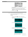
На соответствующих экранах, текущий уровень доступа обозначается иконкой
в верхней строке справа (см. таблицу выше и пример экрана).
Рис. 3. Экран с иконкой текущего уровня доступа
По умолчанию, вся информация доступная для просмотра с самым низким
уровнем доступа (ввод пароля не требуется) отображается на экранах
(с закрытым замком).
С любого экрана, на котором отображена иконка уровня доступа, можно ввести
пароль. Выделите иконку путем поворота поворотно-нажимной кнопки и
нажмите на неё, для вывода запроса на ввод пароля.
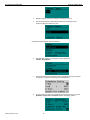
Ввод Пароля (Уровень 2 и 3) в меню Домашнего экрана
ПРИМ.:
Пароль по умолчанию для Уровня-2: '2222'.
Пароль по умолчанию для Уровня-3: '3333'.
Функции Уровня-3 дополнительно доступны через Сервисное меню.
Если вы ввели пароль доступа с домашнего экрана, то перейдя в
Сервисное меню, повторно вводить пароль не требуется.
Процедура
1.
RU2B-0361GE51 R1011
На экране, на котором отображается иконка уровня доступа в
заглавной строке, выделите иконку пароля путем поворота поворотнонажимной кнопки.
16
КОНТРОЛЛЕР MVC
ФУНКЦИОНИРОВАНИЕ
2.
Нажмите на поворотно-нажимную кнопку. Появится запрос на ввод
пароля. По умолчанию, первая мигающая цифра 5.
3.
Используя поворотно-нажимную кнопку, введите все 4 цифры пароля.
4.
После успешного ввода пароля, строка с кодом доступа будет скрыта и
иконка закрытого замка сменится на другую (отрытый замок или
гаечный ключ в зависимости от введенного пароля):
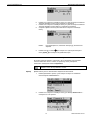
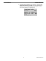
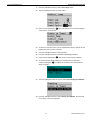
Ввод Пароля (Уровень 3) в Сервисном меню
Для получения доступа к важным настройкам необходимо ввести пароль
уровня доступа 3. При необходимости пароль уровня доступа 2 и уровня
доступа 3 можно изменить, см. раздел “Изменение Пароля”.
ПРИМ.:
Пароль доступа для Уровня 3 - '3333'.
Процедура
1.
Нажмите кнопку Сервис
17
. Отобразиться Сервисное меню.
RU2B-0361GE51 R1011
ФУНКЦИОНИРОВАНИЕ
КОНТРОЛЛЕР MVC
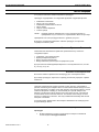
2.
Поверните поворотно-нажимную кнопку для перемещения и выделения
Вход для Инженера, и нажмите кнопку для подтверждения.
3.
Появится запрос на ввод пароля.
4.
Введите пароль, используя поворотно-нажимную кнопку.
5.
Нажмите на поворотно-нажимную кнопку для сохранения первой
введенной цифры, после чего начнет мигать вторая цифра пароля.
6.
После ввода последней цифры и принятия пароля отобразится экран
со словом «Далее»:
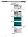
7.
Выделите Далее используя поворотно-нажимную кнопку и нажмите
кнопку для входа. Отобразится меню Сервис, как показано на примере:
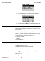
8.
Используйте поворотно-нажимную кнопку для навигации по меню.
9.
Если вы нажмете кнопку Дом
для выхода на Домашний экран,
появится вопрос об отмене введенного уровня доступа.
10. Выберите один из ответов:
RU2B-0361GE51 R1011
18
КОНТРОЛЛЕР MVC
ФУНКЦИОНИРОВАНИЕ
– Да
После выхода, вам будет необходимо вводить пароль снова для
доступа к защищенным функциям.
– Нет
После выхода, вам не понадобится вводить пароль снова для
доступа к защищенным функциям.
Вы попадете в меню Домашнего экрана. Иконка гаечного
ключа отображается в правом верхнем углу.
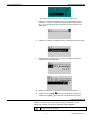
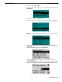
Изменение Пароля
Для доступа к функциям обслуживания необходимо ввести пароль с уровнем
доступа 3. Если пароль с уровнем доступа 3 введен и принят контроллером, то
можно изменить существующие пароли для уровня доступа 2 и уровня 3.
ПРИМ.:
Пароль доступа для Уровня 2 - '2222'.
Пароль доступа для Уровня 3 - '3333'.
Процедура
1.
Нажмите кнопку Сервис
2.
Поворачивая поворотно-нажимную кнопку выделите Вход для
Инженера и нажмите кнопку для входа в под-меню. Отобразится
следующий экран:
3.
Поворачивая поворотно-нажимную кнопку выделите Изменить Пароль
и нажмите кнопку для входа в под-меню. Отобразится следующий
экран:
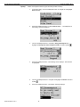
4.
Измените пароль на желаемый (Уров. 2 и/или Уров.3) тем же методом,
как и в разделе “Ввод Пароля (Уровень 3)”. Следующий экран показан в
качестве примера.
19
. Отобразится Сервисное меню.
RU2B-0361GE51 R1011
ФУНКЦИОНИРОВАНИЕ
КОНТРОЛЛЕР MVC
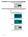
5.
Нажмите кнопку Отмена C для выхода из этого экрана.
Повторный ввод Пароля
Во время работы в области защищенной паролем, то повторный ввод пароля
может потребоваться в следующих случаях:
• Если никакие данные не были введены в течение времени автоматического
выхода - 10 минут.
• При нажатии кнопки Дом
и сброса уровня доступа при выходе.
• Если введен неверный пароль.
Возврат к Домашнему экрану со сбросом пароля
После того, как вы ввели пароль (и он был принят) или изменили его, при
, вы увидите на экране запрос о сохранении уровня
нажатии кнопки Дом
доступа при выходе. Если вы ответите Да, то вам будет необходимо повторно
вводить пароля для получения доступа к защищенной паролем области.
Процедура
RU2B-0361GE51 R1011
. Отобразится следующий экран:
1.
Нажмите кнопку Дом
2.
Путем поворота поворотно-нажимной кнопки выделите Да.
Отобразится следующий экран:
20
КОНТРОЛЛЕР MVC
ФУНКЦИОНИРОВАНИЕ
3.
Нажмите поворотно-нажимную кнопку. Произойдет выход со сбросом
пароля и отобразится следующий экран:
4.
Обзор и Редактирование Информации
Базовые процедуры:
•
•
•
•
•
•
•
Отображение меню Домашнего экрана
Вызов Меню
Отмена Действия
Навигация по Меню, Спискам и выделенным элементам
Выделение элемента
Настройка и сохранение опций и значений
Работа с Командными Символами
Меню Домашнего экрана
Перейти на меню Домашнего экрана можно из любого места рабочей
. В меню
последовательности экранов путем нажатия кнопки Дом
Домашнего экрана отображаются компоненты системы и другие разделы, к
которым необходим быстрый доступ (так называемые Списки Быстрого
Доступа (СБД)).
Возврат к Домашнему экрану происходит автоматически, если ни одна кнопка
на контроллере не была нажата в течение 10 минут.
21
RU2B-0361GE51 R1011
ФУНКЦИОНИРОВАНИЕ
КОНТРОЛЛЕР MVC
Вызов Меню
Меню можно вызвать из любого места экранной последовательности путем
нажатия на функциональную кнопку. Подробности см. в разделе
«Функциональные кнопки».
Пример:
Выбор меню «Тревоги».
Пример Домашнего экрана:
!
1.
Нажмите кнопку Тревоги
. Отобразится меню Тревог
2.
Используйте поворотно-нажимную кнопку для навигации и выбора
элементов меню.
Отмена Действия
В любом месте экранной последовательности, нажатие на кнопку Отмена C
приводит к возврату на предыдущий экран, отменяет введенное значение
(если не сохранено) и подтверждению поступившей тревоги.
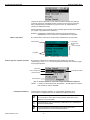
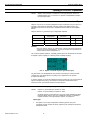
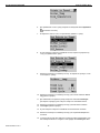
Навигация по Меню, Спискам и выделенным элементам
Во время навигации по списку путем поворота поворотно-нажимной кнопки,
элементы списка автоматически выделяются (подсвечиваются) при повороте
кнопки по часовой стреле или против часовой стрелке.
Если список организован одной колонкой, то навигация/выделение происходит
только по вертикали.
Рис. 4. Вертикальная навигация в меню Тревоги
Если список организован в несколько колонок, то навигация производится
вертикально и горизонтально. При этом, любой элемент можно выделить
путем поворота поворотно-нажимной кнопки по часовой стреле или против
часовой стрелке.
RU2B-0361GE51 R1011
22
КОНТРОЛЛЕР MVC
ФУНКЦИОНИРОВАНИЕ
Первый выделенный
элемент (выделение
по умолчанию)
Последний выделенный
элемент (конец
навигации)
Рис. 5. Вертикальная и Горизонтальная навигация
Выбор Элемента
Выбор элемента списка производится нажатием на поворотно-нажимную
кнопку
в то время, как элемент выделен.
В зависимости от выделенного элемента, результат может быть разным.
Выбор Меню и Элемента Списка
Выбор Значения и Опций
Выбор меню и списка элементов путем нажатия поворотно-нажимной кнопки
на выделенном (подсвеченном) элементе, обычно приводит в под-меню,
например, точки из меню контура отопления.
Выделение значения или опции путем нажатия поворотно-нажимной кнопки на
выделенном (подсвеченном) элементе является первым шагом для настройки
значения и опции. Подробности см. в разделе “Настройка и сохранение Опций
и Значений”.
23
RU2B-0361GE51 R1011
ФУНКЦИОНИРОВАНИЕ
КОНТРОЛЛЕР MVC
Пример: Выбор и настройка комнатной температуры контура отопления.
Выбор Управляющих Функций
Выбор символа командной функции приводит к множеству различных
функций, таких как:
•
•
•
•
•
•
Изменение Режима Работы
Изменение Расписания
Правка Элементов
Добавление Элементов в Список
Удаление Элементов
и другие
Подробности см. В разделе “Работа с Командными Символами”.
Настройка и Сохранение Опций и Значений
Опции настраиваются путем выбора записей состояний из списка, например,
выбор статуса насоса СТОП или ПУСК. Значения задаются цифрами, как
например, температура в градусах Цельсия.
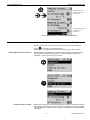
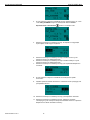
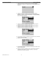
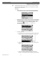
Настройка и Сохранение Опций
Пример: Изменение статуса работы насоса контура ГВС
3.
RU2B-0361GE51 R1011
В меню Домашнего экрана, поверните поворотно-нажимную кнопку и
выделите Контур ГВС.
24
КОНТРОЛЛЕР MVC
ФУНКЦИОНИРОВАНИЕ
4.
Нажмите на поворотно-нажимную кнопку для входа в под-меню.
Отобразятся точки данных относящиеся к работе контура ГВС.
5.
Поворачивая поворотно-нажимную кнопку найдите точку НГВС2_ВКЛ и
выделите опцию со статусом, в данном случае СТОП ´Stopped`.
Обратите внимание, что точка находится в автоматическом режиме
работы, о чем свидетельствует символ
справа от названия точки.
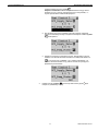
6.
Нажмите на поворотно-нажимную кнопку для выбора опции. Поле с
опцией начнет мигать.
7.
Измените значение мигающей опции путем поворота поворотнонажимной кнопки с ВЫКЛ. на ВКЛ . Поле будет продолжать мигать.
8.
Нажмите на поворотно-нажимную кнопку для сохранения нового
значения опции. Поле перестанет мигать и будет выделено, и
командный символ Автоматического режима работы
символ режима Ручного управления
25
изменится на
.
RU2B-0361GE51 R1011
ФУНКЦИОНИРОВАНИЕ
КОНТРОЛЛЕР MVC
ПРИМ.: Вы также можете изменить режим работы через командный
символ. Выделите символ и измените опцию.
Настройка и Сохранение Значений
Пример: Настройка комнатной температуры.
1.
In the Home menu, turn the rotate&push button to navigate to and highlight
Heat Circuit 1... .
2.
Push the rotate&push button to select Heat Circuit 1… . The datapoints of
the heating circuit are displayed.
3.
If not already selected, turn the rotate&push button to navigate to HC1_
Roomsetpoint and highlight the value. Note that the room temperature is in
automatic operating mode as indicated by the Automatic symbol
the HC1_ Roomsetpoint field.
RU2B-0361GE51 R1011
right to
4.
Push the rotate&push button to select the value. The value is flashing.
5.
Turn the rotate&push button to change (increase or decrease) the value.
26
КОНТРОЛЛЕР MVC
ФУНКЦИОНИРОВАНИЕ
6.
Push the rotate&push button to save the value. The Auto command symbol
is changed accordingly to the Manu command symbol
.
NOTE: You can also change the operating mode first by navigating to the
command symbol, selecting the symbol (toggle) and then change the
value in a second step.
Командные Символы
В некоторых местах рабочей последовательности используются командные
символы. В следующих разделах описаны основные функции и процедуры.
Изменение / Отображение Режима Работы
Точки Данных могут иметь следующие режимы работы, отмеченные
соответствующими символами:
Авто
Точка находится в автоматическом режиме и может быть
переключена в ручной режим
Ручной
Точка находится в ручном режиме и может быть переключена в
автоматический режим
Для изменения статуса работы с Авто на Ручной и наоборот, пожалуйста
обратитесь к разделу “Настройка и сохранение Опций и Значений”.
Изменение Настроек Расписаний
Точка Данных может быть назначена как точка переключения в расписаниях.
Значение каждой такой точки может быть переписано путем использования
Особого Переключения Временного Расписания – функция СЕГОДНЯ.
Командные символы, относящиеся к Расписаниям, следующие:
27
RU2B-0361GE51 R1011
ФУНКЦИОНИРОВАНИЕ
КОНТРОЛЛЕР MVC
Расписание (Временная Программа)
Точке присвоено Суточное расписание. Суточное расписание можно
выделить и редактировать.
Особое переключение в Расписании (функция СЕГОДНЯ)
Значение точки может быть переключено для особого периода
времени, в последующие 24 часа. Точке должно быть назначено
суточное расписание.
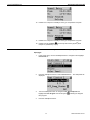
Пример 1
Расписание
Назначение различных суточных расписаний дням недели, путем изменения
недельного расписания, назначенного точке данных – температура в контуре
отопления.
1.
В меню Домашнего экрана, поверните поворотно-нажимную кнопку для
выделения Контур Отопления.
2.
Нажмите на поворотно-нажимную кнопку для входа в под-меню Контур
Отопления. Отобразятся точки данных, которые имеют отношение к
работе Контура Отопления.
3.
Путем поворота поворотно-нажимной кнопки, переместитесь до соотв.
точки HC2_Roomsetpoint и выделите командный символ Расписания
справа от названия точки.
4.
RU2B-0361GE51 R1011
Нажмите на поворотно-нажимную кнопку. Название назначенного
расписания отобразится в первой строке. Запись ´Spcl. Day` (СпецДень
– расписание для специального дня) будет выделена.
28
КОНТРОЛЛЕР MVC
ФУНКЦИОНИРОВАНИЕ
Пример 2
5.
Путем поворота поворотно-нажимной кнопки выделите название
суточного расписания, которое присвоено понедельнику. В данном
случае, название суточного расписания´Workday` (РАБДЕНЬ).
6.
Нажмите на поворотно-нажимную кнопку.
7.
Путем поворота поворотно-нажимной кнопки измените название
расписания на ´Holiday` (ВЫХОДНОЙ).
8.
Сохраните присвоенное новое расписание путем нажатия на
поворотно-нажимную кнопку.
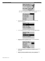
Особое Переключение в Расписании (функция СЕГОДНЯ)
Переключение (перезапись) значения точки данных для особого периода
времени, в течение ближайших 24 часов. В данном примере
продемонстрирована перезапись уставки ГВС с 55.0°С до 45.0°C на период в 3
часа.
C
1.
В меню Домашнего экрана, поверните поворотно-нажимную кнопку для
выделения Контур ГВС.
2.
Нажмите на поворотно-нажимную кнопку для входа в под-меню Контур
ГВС. Отобразятся точки данных, которые имеют отношение к работе
Контура Отопления.
29
RU2B-0361GE51 R1011
ФУНКЦИОНИРОВАНИЕ
КОНТРОЛЛЕР MVC
3.
Путем поворота поворотно-нажимной кнопки, переместитесь до соотв.
точки ГВС_УСТАВКА и выделите командный символ Особое
Переключение в Расписании
справа от названия точки.
4.
Нажмите на поворотно-нажимную кнопку. Отобразится следующий
экран. Время начала будет выделено.
5.
Нажмите на поворотно-нажимную кнопку и измените часы путем
поворота поворотно-нажимной кнопки.
Нажмите на поворотно-нажимную кнопку и измените минуты путем
поворота поворотно-нажимной кнопки.
Нажмите на поворотно-нажимную кнопку для сохранения введенного
значения.
6.
7.
8.
Путем поворота поворотно-нажимной кнопки выделите время
окончания.
9.
Задайте время окончания аналогично описанной выше процедуре, как
для времени начала.
10. Нажмите на поворотно-нажимную кнопку для выделения значения.
11. Нажмите на поворотно-нажимную кнопку, измените значение
температуры путем поворота поворотно-нажимной кнопки и сохраните
введенное значение нажатием на кнопку.
RU2B-0361GE51 R1011
30
КОНТРОЛЛЕР MVC
ФУНКЦИОНИРОВАНИЕ
12. Нажмите кнопку Отмена C для выхода из этого экрана. Статус
действия особого переключения в расписании отмечен буквой ´T`
слева от командного символа.
Буква информирует, значение какой программы активно:
– Нет буквы = недельное расписание
– T = особое временное расписание
– A = годовое расписание
– B = расписание выходного дня (ВЫХОДНОЙ)
Правка Элементов
Некоторые элементы могут быть отредактированы. Рядом с записями, которые
поддаются правке, расположен командный символ Правка:
Правка
Элемент можно редактировать
Пример
Правка времени переключения комнатной температуры контура отопления,
управляемого в соответствии с назначенным суточным расписанием ´Workday`
(Рабочий День).
Меню Домашнего экрана:
1.
В меню Домашнего экрана, путем поворота поворотно-нажимной
кнопки выделите Heat Circuit 1... и нажмите на нее для входа в под
меню. Отобразятся токи относящиеся к Heat Circuit 1.
2.
Поворачивая поворотно-нажимную кнопку, переместитесь до точки HC1
Roomsetpoint и выделите командный символ Расписание
расположенный справа от названия точки.
31
RU2B-0361GE51 R1011
ФУНКЦИОНИРОВАНИЕ
КОНТРОЛЛЕР MVC
Название назначенного расписания отображается в первой стоке
экрана слева. Запись ´СпецДень`/´Spcl. Day` (расписание
специального дня) выделена.
3.
Поворачивая поворотно-нажимную кнопку выделите командный символ
Права
справа напротив ´Mo Workday`.
Отобразятся точки переключений суточного расписания ´Workday`.
Командный символ Добавить выделен (подсвечен). Если
необходимо, то Вы можете добавить точку переключения нажатием
поворотно-нажимной кнопки (см. раздел Добавление ).
RU2B-0361GE51 R1011
4.
Путем поворота поворотно-нажимной кнопки, выделите точку
переключения из списка.
5.
Нажмите на кнопку при выделенной точке. Отобразится время начала
периода и температура для периода. Время начала будет выделено
(подсвечено).
32
КОНТРОЛЛЕР MVC
ФУНКЦИОНИРОВАНИЕ
6.
7.
8.
Нажмите на поворотно-нажимную кнопку и путем ее поворота измените
значение времени начала (часы) периода на желаемое.
Нажмите на поворотно-нажимную кнопку и путем ее поворота измените
значение времени начала (минуты) периода на желаемое.
Сохраните время начала путем нажатия на поворотно-нажимную
кнопку.
ПРИМ.:
9.
При необходимости, измените температуру аналогичным
образом.
Нажмите кнопку Отмена C для возврата на один экран назад или
кнопку Дом
для возврата на Домашний экран.
Добавление Элемента в Список
В соответствующих экранах, списки могут быть расширены дополнением
новых элементов в список. Списки, которые могут быть расширены,
обозначены командным символом Добавить:
Добавить
Элемент может быть добавлен в список.
Пример
Добавление Суточного Расписания в Недельное Расписание.
1.
В меню Домашнего экрана, путем поворота поворотно-нажимной
кнопки выделите Heat Circuit 1... .
2.
Нажмите на поворотно-нажимную кнопку для выбора Heat Circuit 1… .
Отобразятся точки данных.
33
RU2B-0361GE51 R1011
ФУНКЦИОНИРОВАНИЕ
КОНТРОЛЛЕР MVC
3.
Путем поворота поворотно-нажимной кнопки переместитесь до точки
HC1_Roomsetpoint и выделите командный символ Расписание
справа от названия точки.
4.
Нажмите на поворотно-нажимную кнопку.
Название назначенного расписания отображается в первой стоке
экрана слева. Запись ´СпецДень`/´Spcl. Day` (расписание
специального дня) выделена.
5.
Нажмите на поворотно-нажимную кнопку для выбора ´СпецДень`.
Отобразится экран с названиями Специальных расписаний.
6.
Поверните поворотно-нажимную кнопку для выделения Суточные
Расписания.
Следующий экран отобразится, если никакой временной программы
еще не было назначено. Командный символ Добавить
Продолжение с шага 7.
выделен.
Если расписания уже были назначены ранее, то отобразится
следующий экран.
RU2B-0361GE51 R1011
34
КОНТРОЛЛЕР MVC
ФУНКЦИОНИРОВАНИЕ
Вы можете выбрать расписание из списка и изменить его.
7.
Нажмите на поворотно-нажимную кнопку. A new blank daily program
named DP_1 is inserted. Further daily programs will be named as DP_2,
DP_3, etc. In the following steps you will add the switching points to the
daily program.
8.
Нажмите на поворотно-нажимную кнопку. The datapoint name is inserted.
9.
Задайте время и температуру как описано в разделе “Настройка и
Сохранение Опций и Значений”.
10. Добавьте следующую точку переключения как описано выше.
11. Нажмите кнопку Отмена C для выхода из текущего экрана и/или
нажмите кнопку Дом
для перехода в меню Домашнего экрана.
Удаление Элементов
Некоторые элементы могут быть удалены. Рядом с записями, которые
поддаются удалению, расположен командный символ Удалить:
Удалить
Элемент может быть удален
35
RU2B-0361GE51 R1011
ФУНКЦИОНИРОВАНИЕ
КОНТРОЛЛЕР MVC
Пример
Delete an Exceptional Time Program Override (TODAY function)
1.
In the Home menu, turn the rotate&push button to navigate to and highlight
Heat Circuit 2… .
2.
Push the rotate&push button to select Heat Circuit 2… . The datapoints of
the heating circuit are displayed.
3.
Turn the rotate&push button to navigate to HC2_Roomsetpoint and
highlight the Exceptional Time Program Override command symbol
4.
Push the rotate&push button. The following screen displays. The start time
is highlighted.
5.
Turn the rotate&push button to navigate and highlight the Delete command
symbol
6.
RU2B-0361GE51 R1011
.
.
Push the rotate&push button. The deletion message displays.
36
КОНТРОЛЛЕР MVC
ФУНКЦИОНИРОВАНИЕ
7.
Turn the rotate&push button to select Yes, and then push the rotate&push
button. The exceptional time program override is deleted indicated by the
display of the actual time for the start and stop time and no value (********).
8.
Press the Cancel key C to leave the screen. The Heat Circuit 2 screen
redisplays. It shows that the normal time program is active again. The ´T`
character left from the Exceptional Time Program Override command
symbol
is removed.
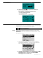
Разрешение/Запрещение Элементов
Элемент может быть разрешен или запрещен путем отметки в чекбоксе:
Разрешено/Запрещено
Элемент разрешен (чекбокс отмечен галочкой) или запрещен
(чекбокс не отмечен)
Пример
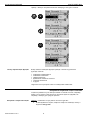
Разрешение/Запрещение настройки “Добавить номер bus к названию точки” в
Сервисном меню.
. Отобразится экран с Сервисным Меню:
1.
Нажмите кнопку Сервис
2.
Путем поворота поворотно-нажимной кнопки выделите
Вход для Инженера и нажмите на кнопку.
3.
Появится запрос на ввод пароля. Нажмите на поворотно-нажимную
кнопку. Поле для ввода пароля станет активным.
37
RU2B-0361GE51 R1011
ФУНКЦИОНИРОВАНИЕ
КОНТРОЛЛЕР MVC
4.
Введите пароль используя поворотно-нажимную кнопку.
5.
После ввода пароля, поворачивая поворотно-нажимную кнопку
выделите Далее и нажмите на нее.
Отобразится меню Сервис (Обслуживание):
RU2B-0361GE51 R1011
6.
Поворачивая поворотно-нажимную кнопку выделите
Конфиг. Интрефейса.
7.
Нажатием поворотно-нажимной кнопки произведите вход в под-меню.
Отобразится под-меню Конфигурация Интерфейса.
8.
Путем поворота поворотно-нажимной кнопки переместитесь к опции
Добавить номер bus к названию точки и выделите чекбокс.
38
КОНТРОЛЛЕР MVC
ФУНКЦИОНИРОВАНИЕ
9.
Нажатием поворотно-нажимной кнопки разрешите / запретите опцию
Добавления номера bus к названию точки. Если опция разрешена
(чекбокс отмечен галочкой), то номер шины будет добавляться к
названию точек, если опция запрещена (чекбокс пустой), то номер
шины не будет добавляться к названию точек.
39
RU2B-0361GE51 R1011
ФУНКЦИОНИРОВАНИЕ
КОНТРОЛЛЕР MVC
Частые операции
Этот раздел описывает общие ежедневные процедуры.
Процедуры сгруппированы по следующим функциям следующим образом:
•
•
•
•
•
•
Изменение Расписаний
Обзор Статуса Установки
Изменение Режима Работы Насоса
Обзор Тревог
Подсчет Часов Наработки
Точки в Тренде
ПРИМ.:
Примеры экранов приведенные в этом руководстве являются
примерами и могут отличаться от экранов вашего MVC контроллера.
Проведение всех этих процедур возможно с уровнем доступа -1.
В разделе “Специальные Действия” описаны процедуры, которые вам
потребуются намного реже.
Изменение Временных Расписаний
Самые важные изменения во временных расписаниях могут включать
следующие задачи:
•
•
•
•
Изменение точки переключения
Время расширенной работы
Ввод отпускного расписания
Ввод расписания для выходных и праздничных дней
Для дополнительной информации обратитесь к последовательности, см. Рис.
8, p.61; Fig. 16, p. 68.
Изменение Точки Переключения
Вы можете изменить время и/или температуру для точки переключения.
Для обзора процедуры, обратитесь к примеру описанному в разделе “Правка
Элемента”.
Время Расширенной Работы
Using the exceptional time program override (“Today” function), it is possible to
perform on/off changes to setpoint values or control states without having to access
the annual program or to define a new daily program. New setpoint values or control
states and the period of validity (i.e. start and end) for a specific datapoint are
defined. The start time must be within 24 hours from the entry time. The end time
must be within 24 hours from the start time. The duration of the change can thus
amount to a maximum of 48 hours. The entry is deleted automatically after the end
time point is exceeded.
For the procedure, please refer to the example 2 described in the “Changing Time
Program Settings” section.
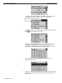
Ввод Отпускного Расписания
Процедура
1.
RU2B-0361GE51 R1011
В меню Домашнего экрана, путем поворота поворотно-нажимной
кнопки выделите Контур Отопления.
40
КОНТРОЛЛЕР MVC
ФУНКЦИОНИРОВАНИЕ
2.
Нажмите на поворотно-нажимную кнопку для входа в под-меню Контур
Отопления. Отобразятся следующие точки.
3.
Путем поворота поворотно-нажимной кнопки найдите из списка точек,
точку с названием HC2_Roomsetpoint и выделите командный символ
Времен. Расписание
Расписанием.
4.
показывающий, что точка управляется
Нажмите на поворотно-нажимную кнопку.
Название назначенного расписания отобразится в первой строке.
Запись ´СпецДень` (Программы Специального Дня) будет выделена.
5.
Нажмите на поворотно-нажимную кнопку для выбора ´СпецДень`.
Отобразятся программы специального дня.
6.
Путем поворота поворотно-нажимной кнопки выделите Годовое
Расписание.
41
RU2B-0361GE51 R1011
ФУНКЦИОНИРОВАНИЕ
КОНТРОЛЛЕР MVC
7.
Нажмите на поворотно-нажимную кнопку для выбора Годовое
Расписание. Отобразится следующий экран. Символ Добавить будет
выделен.
8.
Нажмите на поворотно-нажимную кнопку для выбора символа
Добавить. Отобразится экран Годовая Запись, где возможно ввести
дату отпуска (время, необходимо использовать суточное расписание).
Дата начала будет выделена.
9.
Нажмите на поворотно-нажимную кнопку. Используйте поворотнонажимную кнопку для изменения первой цифры.
10. Нажмите на поворотно-нажимную кнопку. Используйте поворотнонажимную кнопку для изменения второй цифры.
11. Нажмите на поворотно-нажимную кнопку. Используйте поворотнонажимную кнопку для изменения третьей цифры.
12. Путем поворота поворотно-нажимной кнопки выделите дату окончания
отпуска )справа од поля До).
13. Введите дату окончания аналогичным образом.
14. Путем поворота поворотно-нажимной кнопки выделите нижнюю строку
Суточное Расписание.
15. Нажмите на поворотно-нажимную кнопку. Путем поворота поворотнонажимной кнопки выделите суточную программу, которая будет
применена для отпускного периода.
RU2B-0361GE51 R1011
42
КОНТРОЛЛЕР MVC
ФУНКЦИОНИРОВАНИЕ
16. Нажмите на поворотно-нажимную кнопку для сохранения настроек.
17. Нажмите на поворотно-нажимную кнопку для сохранения настроек.
18. Нажмите кнопку Отмена C для выхода и/или кнопку Дом
для
возврата к домашнему экрану.
Назначение Суточного Расписания для Праздничного дня
Процедура
1.
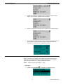
In the Home menu, turn the rotate&push button to navigate to and highlight
Heat Circuit 2... .
2.
Push the rotate&push button to select Heat Circuit 2… . The datapoints are
displayed.
3.
Turn the rotate&push button to navigate to HC2_Roomsetpoint and
highlight the Time Program command symbol
time program.
4.
indicating an assigned
Push the rotate&push button.
43
RU2B-0361GE51 R1011
ФУНКЦИОНИРОВАНИЕ
КОНТРОЛЛЕР MVC
The name of the assigned time program is displayed in the first line. The
entry ´Spcl. Day` (special day programs) entry is highlighted.
RU2B-0361GE51 R1011
5.
Push the rotate&push button to select ´Spcl. Day`. The special day
programs are displayed.
6.
Turn the rotate&push button to navigate to and highlight Bank Holiday.
7.
Нажмите на поворотно-нажимную кнопку для выбора Праздники.
Отобразится список Праздничных дней.
8.
Путем поворота поворотно-нажимной кнопки выделите поле справа от
названия Праздника, которому вы хотите назначить суточное
расписание.
9.
Нажмите на поворотно-нажимную кнопку и затем, поверните ее для
выбора суточного расписания из списка суточных расписаний.
44
КОНТРОЛЛЕР MVC
ФУНКЦИОНИРОВАНИЕ
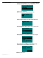
10. Нажмите на поворотно-нажимную кнопку для выбора суточного
расписания
11. Нажмите на поворотно-нажимную кнопку для сохранения настроек.
12. Нажмите кнопку Отмена C для выхода и/или кнопку Дом
для
возврата к домашнему экрану.
Обзор Информации Статуса Компонента Системы
Цель
Например, для просмотра статуса насоса в контуре отопления.
Для дополнительной информации обратитесь к последовательности, please
refer to Error! Reference source not found. Fig. 6, p. 62.
Процедура
1.
В меню Домашнего экрана, путем поворота поворотно-нажимной
кнопки выделите компонент системы, например, Контур Отопления.
2.
Нажмите на поворотно-нажимную кнопку для входа в под-меню Контур
Отопления. Отобразится список точек относящихся к компонентам
Контура Отопления и под названием каждой точки, будет отображена
статусная информация. Статус насоса HC2_Pump_Status - ´Off` и
информирует, что точка работает в
командный символ
автоматическом режиме
45
RU2B-0361GE51 R1011
ФУНКЦИОНИРОВАНИЕ
КОНТРОЛЛЕР MVC
Изменение Режима Работы Насоса
Цель
Изменение режима работы насоса с Автоматического на Ручной и наоборот.
Для дополнительной информации обратитесь к последовательности, please
refer to Рис. 8, p.61; Fig. 6, p. 62.
Процедура
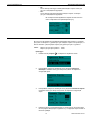
1.
В меню Домашнего экрана, путем поворота поворотно-нажимной
кнопки выделите компонент системы, например, Контур Отопления.
2.
Нажмите на поворотно-нажимную кнопку для входа в под-меню Контур
Отопления. Отобразится список точек относящихся к компонентам
Контура Отопления и под названием каждой точки, будет отображена
статусная информация. Статус насоса HC2_Pump_Status - ´Off` и
информирует, что точка работает в
командный символ
автоматическом режиме
3.
Сделайте следующее:
a. Для перевода насоса из Автоматического режима в Ручной, путем
поворота поворотно-нажимной кнопки выделите статусный текст.
b. Нажмите на поворотно-нажимную кнопку и затем, поворачивая ее
выберите ´ВКЛ`.
c. Нажмите на поворотно-нажимную кнопку для подтверждения
изменения. Точка управления насосом перейдет в Ручной режим и
RU2B-0361GE51 R1011
46
КОНТРОЛЛЕР MVC
ФУНКЦИОНИРОВАНИЕ
появится символ Ручного режима
.
Обратите внимание! Изменения в расписаниях не будут иметь
влияния на статус насоса, находящегося в Ручном режиме, т.к.
Ручной режим имеет наивысший приоритет.
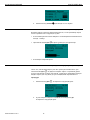
d. Для возврата из Ручного режима в автоматический, поверните
поворотно-нажимную кнопку и выделите командный символ Ручной
режим работы.
e. Нажмите на поворотно-нажимную кнопку. Режим работы насоса
изменится на Автоматический и изменится командный символ на
и статусный текст на ВЫКЛ / ´Off`. Обратите внимание, что
обычно, Автоматический статус работы насоса контролируется
временным расписанием.
4.
Нажмите кнопку Отмена C для выхода и/или кнопку Дом
возврата к домашнему экрану.
47
для
RU2B-0361GE51 R1011
ФУНКЦИОНИРОВАНИЕ
КОНТРОЛЛЕР MVC
Обзор Тревог
Цель
Просмотр любой следующей информации:
•
•
•
•
Текущие точки в тревоге
Критические тревоги
Некритические тревоги
Журнал тревог
Для дополнительной информации обратиесь к последовательности, please
refer to Рис. 8, p.61; Error! Reference source not found.Рис. 10, p. 63.
Процедура
!
1.
Для перехода в меню «Тревоги» нажмите кнопку Тревоги
контроллере.
2.
Используйте поворотно-нажимную кнопку для навигации и выбора подменю:
на
– Журнал Тревог
Список произошедших тревог отсортированный по времени
возникновения
– Точки в Тревоге
список всех точек, находящихся в тревоге в данный момент времени
– Критические Тревоги
список всех точек, находящихся в тревоге в данный момент времени
и имеющие статус Критических.
– Некритические Тревоги
список всех точек, находящихся в тревоге в данный момент времени
и имеющие статус Некритических
3.
Для точки в любой категории, вы можете посмотреть подробности.
a. Используя поворотно-нажимную кнопку выделите тревогу из списка,
подробности по которой вы хотите посмотреть и нажмите
поворотно-нажимную кнопку. Отобразятся подробности тревоги:
RU2B-0361GE51 R1011
48
КОНТРОЛЛЕР MVC
ФУНКЦИОНИРОВАНИЕ
дата и время возникновения, название точки, значение / статус и
текст тревоги.
Подсчет часов наработки
Цель
Подсчет часов наработки компонента системы
For additional information on the operating sequence, please refer to Рис. 8, p.61;
Рис. 12, p. 65.
Процедура
1.
Нажмите кнопку Сервис
2.
Если не выделено Продолжить, выделите путем поворота поворотно
нажимной кнопки и нажмите на нее.
3.
Если не выделено Наработка, выделите путем поворота поворотнонажимной кнопки и нажмите на нее.
4.
В под-меню Наработка будут отображены точки данных, для которых
производится подсчет часов наработки, если они были добавлены
ранее.
5.
Путем поворота поворотно-нажимной кнопки выделите командный
символ Добавить
6.
.
и нажмите на кнопку.
Отобразится список с точками, для которых может производится
подсчет часов наработки:
49
RU2B-0361GE51 R1011
ФУНКЦИОНИРОВАНИЕ
КОНТРОЛЛЕР MVC
7.
Поворачивая поворотно-нажимную кнопку выделите необходимую
точку данных и нажмите кнопку для подтверждения.
8.
Нажмите на поворотно-нажимную кнопку для разрешения подсчета
часов наработки – чекбокс будет отмечен галочкой.
9.
Нажмите на поворотно-нажимную кнопку для разрешения подсчета
часов наработки для выделенных компонентов.
10. Для возврата к списку точек нажмите кнопку Отмена C .
11. При необходимости, повторите описанные действия для всех
требуемых точек.
12. Отображается только полное количество часов наработки:
13. Для запрета и остановки функции подсчета часов наработки
компонента системы, поверните поворотно-нажимную кнопку и
выделите желаемый компонент (точку).
14. Нажмите на поворотно-нажимную кнопку для выбора компонента, e.g.,
Solar_Pump. Отобразятся подробности выбранного компонента
(точки).
RU2B-0361GE51 R1011
50
КОНТРОЛЛЕР MVC
ФУНКЦИОНИРОВАНИЕ
15. Для запрета функции подсчета часов наработки нажмите на поворотнонажимную кнопку.
16. In this screen, you can also view and set further details of the plant
component, e.g., no. of operating hours, no. of switches, status, service
interval, and alarm suppression. The details depend on the type of the plant
component
17. Нажмите кнопку Отмена C .
Запись Тренда
Цель
Задать точки для записи тренда и просмотр журнала тренда.
Для дополнительной информации обратитесь к последовательности, please
refer to Рис. 8, p.61; Рис. 13, p. 65.
Процедура
1.
Нажмите кнопку Сервис
2.
Поверните поворотно-нажимную кнопку для перемещения и выделите
Продолжить.
3.
Нажмите на поворотно-нажимную кнопку.
4.
Поверните поворотно-нажимную кнопку для выделения Тренды.
5.
Нажмите на поворотно-нажимную кнопку для выбора Точки в Тренде.
. Отобразиться Сервисное меню
Экран Точки в Тренде отображает список всех точек, для
которых ведется запись тренда.
51
RU2B-0361GE51 R1011
ФУНКЦИОНИРОВАНИЕ
КОНТРОЛЛЕР MVC
6.
Для добавления точки в тренд, выделите командный символ Добавить
и нажмите на кнопку.
7.
Отобразится список точек, которые можно добавить в тренд.
8.
Путем поворота поворотно-нажимной кнопки, выделите (подсветите)
точку для добавления в тренд.
9.
Нажмите на поворотно-нажимную кнопку. Отобразятся атрибуты точки
относящиеся к тренду.
10. Нажмите на поворотно-нажимную кнопку для отметки чекбокса Trend
Log (Запись Тренда).
11. Для изменения гистерезиса тренда, выделите значение Trend Hyst
(Гистерезис Тренда) путем поворота поворотно-нажимной кнопки.
12. Нажмите на поворотно-нажимную кнопку для изменения значения
13. Trend Hyst (Запись Тренда) .
14. Путем поворота поворотно-нажимной кнопки измените значение.
15. Нажмите на поворотно-нажимную кнопку для сохранения введенного
значения.
16. To set the trend cycle (time period for continuous value measurement), turn
the rotate&push button to navigate to and highlight the Trend Cycle value.
RU2B-0361GE51 R1011
52
КОНТРОЛЛЕР MVC
ФУНКЦИОНИРОВАНИЕ
17. Push the rotate&push button to select Trend Cycle value.
18. Turn the rotate&push button to set the value.
19. Press Cancel operating key C twice. The point is set to trend as displayed
in the Points in Trend screen.
20. To remove a point from trend, turn the rotate&push button to navigate to and
highlight the point you want to remove.
21. Push the rotate&push button to select the point.
22. Push the rotate&push button to disable the Trend Log checkbox.
23. Press Cancel operating key C . The Points in Trend screen redisplays.
24. To view trend point details, display the Trending menu by clicking the
Cancel operating key C . Or, display the Trending menu as described in
steps 1 through 5.
25. Turn the rotate&push button to move to and highlight Display Trend Buffer.
26. Push the rotate&push button to select Display Trend Buffer. All points that
are currently in trend are displayed.
53
RU2B-0361GE51 R1011
ФУНКЦИОНИРОВАНИЕ
КОНТРОЛЛЕР MVC
27. Turn the rotate&push button to navigate to and highlight the point of which
details you want to view.
28. Push the rotate&push button. The trend dates, times and values of the
selected point are displayed.
29. Press Cancel operating key C to return to the trend buffer point list and if
desired view trend details of further points.
Специальные Действия
This section details steps for special procedures that can be executed by the user
having access level-1.
ПРИМ.:
Экраны контроллера, приведенные в этом руководстве, являются
примерами и могут отличаться от экранов вашего контроллера MVC.
In addition to the everyday procedures, the user having access level-1 can perform
the following procedures:
• Правка Точки Данных (значение, запрет тревоги и т.д.)
• Правка Даты /Времени
• Изменение Временных Расписаний
см. раздел «Изменение Временных Расписаний» ” в разделе «Частые
Операции».
• Teach-in a wall module
see “Error! Reference source not found.” section
Правка Точки Данных
Цель
Эта функция позволяет править различные данные точки, например:
•
•
•
•
Изменение значения/статуса точки
Изменение режима работы(автоматический/ручной)
Подавление тревог точки
Назначение точки для записи тренда
и т.д.
ПРИМ.:
The point data that can be edited depends on the point type, the number
of point attributes, and the read and write access level assigned to the
point.
Для дополнительной информации обратитесь к последовательности, please
refer to Рис. 18, p. 70
Процедура
RU2B-0361GE51 R1011
54
КОНТРОЛЛЕР MVC
ФУНКЦИОНИРОВАНИЕ
1.
Нажмите кнопку Сервис
2.
Поверните поворотно-нажимную кнопку для перемещения и выделите
Продолжить.
3.
Нажмите на поворотно-нажимную кнопку.
4.
Поверните поворотно-нажимную кнопку для выделения Точки Данных.
5.
Нажмите на поворотно-нажимную кнопку для входа в под-меню Точки
Данных.
6.
Turn the rotate&push button to navigate to and highlight the point type, e.g.,
Binary Input.
Push the rotate&push button to select Binary Input.
7.
8.
9.
.
Turn the rotate&push button to navigate to and highlight the point, e.g.,
´HCI_Pump_Sta Off`.
Push the rotate&push button to select ´HCI_Pump_Sta Off`. The point data
(attributes) are displayed. Some data can be changed and others can not.
55
RU2B-0361GE51 R1011
ФУНКЦИОНИРОВАНИЕ
КОНТРОЛЛЕР MVC
10. Turn the rotate&push button to navigate to and highlight the attribute and
then edit the attribute, e.g., changing the status from Off to On.
Изменение Даты и Времени
Цель
Изменить дату, время, формат отображения и время перехода на летнее
время.
Процедура
1. Перейдите в под-меню «Дата / Время»:
Сервис Î Продолжить Î Систем. Данные Î Дата / Время
2.
Выделите под-меню Дата / Время и нажмите поворотно-нажимную
кнопку.
3.
Используйте поворотно-нажимную кнопку для навигации по меню и
выделите элемент для изменения.
4.
Нажмите поворотно-нажимную кнопку и измените значение (Дата,
Время и т.д.)
ПРИМ.:
RU2B-0361GE51 R1011
Для изменения времени перехода на Летнее время, выберите
Летнее Время и измените настройку.
56
КОНТРОЛЛЕР MVC
ФУНКЦИОНИРОВАНИЕ
57
RU2B-0361GE51 R1011
ФУНКЦИОНИРОВАНИЕ
КОНТРОЛЛЕР MVC
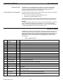
Рабочая Последовательность
Следующие блок-схемы отображают все рабочие последовательности в
контроллере MVC:
•
•
•
•
•
•
•
•
•
•
•
•
•
•
•
Стартовая последовательность
Сброс контроллера
Обзор
Меню Домашнего экрана
Тревоги
Сервис
Наработка
Тренды
Конфигурация Интерфейса
Wall module Teach-in
Дата / Время
Расписания
Суточная программа
Точки Данных
Системные Данные
NOTE:
Operating sequences can refer to other operating sequences within the
schematic. A reference table below the source schematic guides you to
the corresponding figures and pages of the target schematics.
A reference table below the target schematic shows the link to the
corresponding figures and pages of the source schematics.
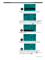
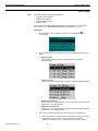
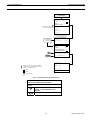
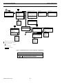
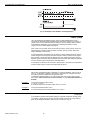
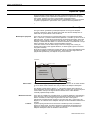
Стартовая Последовательность
The initial display of the controller after power-up varies depending on the delivery
status of the controller. The controller is available in 2 variants.
• Extended version
with configurable startup sequence with language selection and the possibility to
set parameters such as actuator type etc. before application start.
Schematic please see next page.
RU2B-0361GE51 R1011
58
КОНТРОЛЛЕР MVC
ФУНКЦИОНИРОВАНИЕ
Рабочая Последовательность
Запуск
Приложения
(2): 2 backed up (flashed
versions) are available
2009 -07-22
14 :29
Customer _xxxxxxx
C-Bus:
9600
CTR# 04
Выберите Схему :
СХЕМА_01 (2)
СХЕМА_02
СХЕМА_03
СХЕМА_04
СХЕМА_05
Shows all applications available in
the selected language
Use settings
from selected
application
Выберите Применение
Factory
2012 -07-22
15 :00
C-Bus:
9600
CTR# 04
Auto
B-Port :
Довить номер bus
к названию точки
RF
HOME
i
RF Teach -in
Application Config .:
Старт Применения
НАРУЖ_ТЕМП
18 °C
ОТОПЛ_ТЕМП
:
62,5°C
Bold font: system information (non-editable)
Regular font: selectable / editable information
Italic font: application-specific
Сброс тревог
enabled
Контур Отопления
disabled
page up/page down
Fig. 6. Стартовая Последовательность
Continued from Error! Reference source not
found., Error! Bookmark not defined.
Linking icons refer to subsequent sequence as
follows:
RF
HOME
refers to Error! Reference source not
found., p. Error! Bookmark not
defined.
refers to Рис. 9, p. 62
59
RU2B-0361GE51 R1011
ФУНКЦИОНИРОВАНИЕ
КОНТРОЛЛЕР MVC
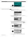
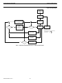
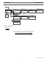
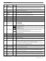
Сброс контроллера
Новый
контроллер
с завода
Стартовая
последовательность
COLD START from FLASH
(last successfully flashed
application, later changes
are lost)
Синхронизация
приводов
yes
no
RAM
OK?
yes
WARM START from
RAM
(appication includes
data whitch was not
flashed)
Сбой
питания
no
Нормальная
работа
СБОЙ ПИТАНИЯ
Сбой программы
(RE-BOOT)
no
yes
> 20 min
Appl. stopped
Рис. 7. Рабочая Последовательность “Сброс контроллера”
RU2B-0361GE51 R1011
60
RESET
Press RESET button
or
Press 2 keys for 3 sec simultaneously:
MVC Buildings: C +
MVC Homes:
OK +
КОНТРОЛЛЕР MVC
ФУНКЦИОНИРОВАНИЕ
Обзор
Рис. 8. Обзор Последовательностей
For further details, please refer to the following figures:
Смотри
Смотри Рис. 11 p. 64
!
Смотри Рис. 10 p. 63
61
RU2B-0361GE51 R1011
ФУНКЦИОНИРОВАНИЕ
КОНТРОЛЛЕР MVC
Меню Домашний экран
Нажата кнопка
Домашний Экран
Shows current operating mode
and allows changing mode :
Уровень доступа >1
?
НЕТ
ДА
Сбросить уровень
доступа ?
Да
Нет
Configuration
HOME SCREEN (Main Menu )
DT
13.08.2010
НАРУЖ_ТЕМП
Displays current user level and allows
selecting user level by selecting symbol
and pushing button to enter password .
Menu shows information according to user
level :
AUTO
14:29
-35.0 °С
Сброс Тревог
Датчики
Т график отопл.
MANU
OVERRIDE
User level 1
User level 2
User level 3
Датчики
SetRoomTemp
20.5°C
T
Pump
ON
RoomTemp
21°C
0002:DerivTime
20.0
Fan
ON
...
SolarAppl
Opens Exceptional time program override
function ) to override current time program
i
00:00
до
Значение
:
Datapoint
M#12
Regular font : selectable / editable information
Italic font : application -specific
page up /page down
Рис. 9. Последовательность “Домашний экран”
Continued from Error! Reference source not found.,
p. Error! Bookmark not defined.; Fig. 6, p. 59
Linking icons refer to subsequent sequence as follows:
TP
refers to Fig. 16 , p. 68
DT
refers to Рис. 15, p. 67
PD
refers to Рис. 18, p. 70
62
11:23
23°C
PD
Start time
Public Parameter
Bold font : system information (non -editable )
RU2B-0361GE51 R1011
(Today
Indicates active time program :
Annual
Bank holiday
Today
no letter = daily
SetRoomTemp
Sub menu
****
TP
Opens active time program :
- Annual time program
- Bank holiday
- Daily time program
End time
HeatingCircuit
SetRoomTemp
23.0°C
T
Pump
ON
RoomTemp
21°C
0002:DerivTime
20.0
Fan
ON
...
SolarAppl
КОНТРОЛЛЕР MVC
ФУНКЦИОНИРОВАНИЕ
Тревоги
Нажата кнопка
ТРЕВОГИ
Тревоги
Буфер Тревог
Точки в ручном режиме
Точки в Тревоге
Критические Тревоги
Буфер
14:36
14:32
14:30
14:26
11:30
11:20
09:00
...
Точки в Ручном режиме
14:36 RoomSetP
14:30 DHW1_Pump
Некритические Тревоги
Тревог
RoomSetP
AlarmMemoryFul
DHW 1_Pump
TotalizerOverf
AI_ModuleDefec
MaintenanceAla
ColdStart
23 . 09 .2010
RoomSetP
14 :36
31.00 °C
В Ручном режиме
Отменить Ручной режим
RoomSetP
Точки в Тревоге
RoomSetP
AlarmMemoryFul
PowerFailure
TotalizerOverf
AI_ModuleDefec
...
i
Bold font: system information (non-editable )
Regular font : selectable / editable information
Italic font: application -specific
page up /page down
Некритические
Тревоги
RoomSetP
AlarmMemoryFul
PowerFailure
TotalizerOverf
AI _ModuleDefec
...
31 . 00 °C
Критические Тревоги
No parameter file
Z-Reg. index error
I/O board missing
Рис. 10. Последовательность меню “Тревоги”
63
RU2B-0361GE51 R1011
ФУНКЦИОНИРОВАНИЕ
КОНТРОЛЛЕР MVC
Сервис (Обслуживание)
Нажата кнопка
ОБСЛУЖИВАНИЕ
Сервисное Меню
Продолжить
Вход для Инженера
Введите Пароль
****
:
Введите Пароль
****
Далее
:
Обслуживание
Наработка
Тренды
Конфиг. Интерфейса
Расписания
Точки Данных
Систем. Данные
Изменить Пароль
Изменить Пароль:
****
Уров. 2:
****
Уров. 3:
Далее в меню Сервис
i
Bold font: system information (non-editable)
Regular font: selectable / editable information
Italic font: application-specific
Data available in different menues is filtered
according to password level:
Level 3: all access is provided
Level 2: level 2 access provided
Level 1: no password, user data is provided
Рис. 11. Последовательность меню “Обслуживание”
Linking icons refer to subsequent sequence as follows:
RU2B-0361GE51 R1011
OH
См. Рис. 12, p. 65
TR
См. Рис. 13, p. 65
IF
См. Рис. 14, p. 66
TP
См. Fig. 16 , p. 68
PD
См. Рис. 18, p. 70
SY
См. Fig. 19, p. 71
64
OH
TR
IF
TP
PD
SY
КОНТРОЛЛЕР MVC
ФУНКЦИОНИРОВАНИЕ
Наработка
OH
Часов Наработки
ГВС_НАСОС
ПРОНИКН
ПРОТЕЧКА
...
(ч)
1672
12
72
Активировать Подсчет
ГВС_НАСОС
ПРОНИКН
ПРОТЕЧКА
...
ГВС_НАСОС
Часов Наработки :
1672
Часов :
Перекл-й :
543
Статус :
ВЫКЛ.
Интевал Обслуж.
:
2000 ч.
Протечка
Часов Наработки :
:
Последнее Обслуж.
1000 ч.
:
Подавить Тревогу
i
Bold font: system information (non-editable)
Regular font : selectable / editable information
Italic font: application-specific
разрешить
запретить
Пролистывание экранов
Рис. 12. Последовательность “Наработка”
Continued from Рис. 11, p. 12
Тренды
TR
Тренды
Точки в Тренде
Буфер Тренда
Точки в Тренде
DHW2_Temp
...
Буфер Тренда
RoomTemp
...
DHW2_Temp
< Описание точки >
Запись Тренда:
1.0%
Гистерезис:
5 мин
Цикл Тренда:
RoomTemp
28.09. 15:18
28.09. 15:25
28.09. 15:32
28.09. 15:39
28.09. 16:00
28.09. 16:10
...
i
Задание Точки для Тренда
RoomTemp2Set
Circ2Pump
RoomTemp2Set
< Описание точки >
Запись Тренда :
1.0%
Гистерезис :
Цикл Тренда:
5 мин
Trend Cycle>0 Y no trend based on hysteresis
20.00
20.50
20.00
19.50
20.00
21.00
разрешить
запретить
Рис. 13. Последовательность меню “Тренды”
Continued from Рис. 11, p. 12
65
RU2B-0361GE51 R1011
ФУНКЦИОНИРОВАНИЕ
КОНТРОЛЛЕР MVC
Конфигурирование Интерфейса
IF
Конфиг. Интерфейса
.
C - Bus :
76800
CTR # 04
9600
B - Port :
Добавлять номер bus
К названию точки
RF
RF Teach -in
i
Bold font: system information (non-editable)
Regular font : selectable / editable information
Italic font: application -specific
enabled
page up/page down
Рис. 14. Последовательность меню “Конфигурирование Интерфейса”
Продолжение Рис. 11, стp. 64
Linking icons refer to subsequent sequence as follows:
RF
HOME
RU2B-0361GE51 R1011
Смотри Error! Reference source not found.,
стp. Error! Bookmark not defined.
Смотри Рис. 9, стp. 62
66
КОНТРОЛЛЕР MVC
ФУНКЦИОНИРОВАНИЕ
Дата / Время
DT
Дата / Время
21.09 .2011
Дата :
Время :
14:29
21.09.2011
21/09/2011
21-09-2011
2011 -09-21
09/21/2011
21.09.2011
Формат :
Летнее Время
Летнее Время
Воскр-е месяца
Пслд
Начал :
Пслд
Конец:
:
Мар
Окт
Воскр-е месяца
Фиксир.дата
Запрещено
01.03
1-е
2-е
3-е
4-е
Пслд
Янв
Фев
Мар
...
NOTE:
„Disabled“ will switch from DST to standard
time. E.g. DST (Daylight Saving Time) is
enabled and the time displayed on the
controller HMI is 09:00 during DST. Once you
disable DST the time will jump from 09:00 to
08:00.
i
Bold font: system information (non-editable)
Regular font: selectable / editable information
Italic font: application-specific
List selection
Рис. 15. Последовательность меню “Дата / Время”
Продолжение Рис. 9, стр. 62
67
RU2B-0361GE51 R1011
ФУНКЦИОНИРОВАНИЕ
КОНТРОЛЛЕР MVC
Расписания
Menu
TP
New daily prog. with default name
Времен. Расписания
ГВС
ОТОПЛ_1
ОТОПЛ_2
ГВС
Mo РАБДЕНЬ 1
Tu РАБДЕНЬ 1
We РАБДЕНЬ 1
Th РАБДЕНЬ 1
Fr РАБДЕНЬ 1
Sa ВЫХОДНОЙ
Su ВЫХОДНОЙ
...
СпецДень
РАБДЕНЬ 1
05:45 Cir1Pump
06:00 DHW1_Temp
06:30 Temp_Setp
21:00 Cir1Pump
21:00 DHW1_Temp
22:00 Temp_Setp
Специальный День
Годовое Расписание
Выходные и Праздники
Суточные Расписания
Годовое Расписан.
05.01.10 - 12.01.10
13.03.10 - 15.03.10
24.12.10 - 01.01.11
...
Годовая Запись
24.12.2010
С
:
13.09.2010
Дo:
Суточное Расписание :
-----
DP
ВЫХОДНОЙ
РАБДЕНЬ 1 Saturday
Sunday
Holiday
-----
i
ВЫХОДНОЙ
РАБДЕНЬ 1 Saturday
Sunday
Holiday
Жирный шрифт: системная информация (не редактируется)
Regular font: selectable / editable information
Italic font: application-specific
page up/
page down
-----: no program assigned.
Список выбора
Fig. 16. Последовательность меню “Времен. Расписания”
Продолжение Рис. 9, стp. 62; Рис. 11, стp. 12
Linking icons refer to subsequent sequence as follows:
DP
RU2B-0361GE51 R1011
Edit switching point
Workday 1
07 : 00 DHW2_Temp
50.0°C
OPT : ON
РАБДЕНЬ 1
DHW2_Temp
RoomTemp 2Set
Circ 2Pump
...
РАБДЕНЬ 1
22:00 Temp_Setp
18.0°C
OPT: ON
ВЫХОДНОЙ
РАБДЕНЬ 1 Saturday
Sunday
Holiday
Выходные и Праздники
H- Day
Новый Год
----Epiphany
Good Friday
H- Day
H- Day
Easter Sunday
----EasterMon
...
ON
50.0
21.5
OFF
30.0
18.0
Select datapoint
refers to Error! Reference source not found.,
p. Error! Bookmark not defined.
68
Годовая Запись
20 .07 .2010
С :
13 .09 .2010
Дo :
Суточное Расписание :
----ВЫХОДНОЙ
РАБДЕНЬ 1
Saturday
Sunday
Holiday
КОНТРОЛЛЕР MVC
ФУНКЦИОНИРОВАНИЕ
Суточные Расписания
DP
Новое Суточное Расписание с
названием по умолчанию
Добавить Суточное
:
Копировать из :
РАБДЕНЬ 1
ВЫХОДНОЙ
Saturday
Sunday
Holiday
Суточные Расписания
:
Выберите для измен.:
РАБДЕНЬ 1
РАБДЕНЬ 1
ВЫХОДНОЙ
Saturday
Sunday
Holiday
Выбор Точки Данных
Edit a daily program
РАБДЕНЬ 1
05 :45 Cir 1 Pump
06 :00 DHW 1 _Temp
06 :30 Temp _Setp
21 :00 Cir 1 Pump
21 :00 DHW 1 _Temp
22 :00 Temp _Setp
ON
50.0
21.5
OFF
30.0
18.0
Выбор Точки Данных
СP_1
DHW2_Temp
RoomTemp 2Set
Circ 2Pump
СP_1
РАБДЕНЬ 1
DHW 2_Temp
RoomTemp 2Set
Circ 2Pump
Правка точки переключения
РАБДЕНЬ 1
07 : 00 DHW2_Temp
50.0°C
OPT : ON
Правка точки переключения
РАБДЕНЬ 1
07:00 DHW 2_Temp
50 . 0 °C
OPT: ON
РАБДЕНЬ 1
22 :00 Temp _Setp
18 . 0 °C
OPT : ON
i
Bold font: system information (non-editable )
Regular font : selectable / editable information
Italic font: application -specific
page up /page down
List selection
Fig. 17. Последовательность меню “Суточные Расписания”
Продоление Рис. 9, стp. 62
69
RU2B-0361GE51 R1011
ФУНКЦИОНИРОВАНИЕ
КОНТРОЛЛЕР MVC
Точки Данных
PD
Availability dependant on password
Точки Данных
Analog Input
Pseudo Analog
Analog Output
Binary Input
Pseudo Binary
Binary Output
Totalizer
Remote Analog
Remote Binary
or
Binary Output
DHW1_Pump
ElectrHeat
Solar_Pump
Dehumidifier
On
Off
On
Off
DHW1_Pump
DHW1 Pump for office
On
Normally Closed :
Suppress Alarm :
Trend Log :
Tech Adr .:
010102
Remote Binary
Fan
Occupied
...
On
On
Fan
MainFreshAir
i
Analog Output
HeatValveAO1 20.5 %
CoolValveAO2
0.0 %
...
or
Bold font: system information(non-editable)
Regular font: selectable / editable information
Italic font: application-specific
Remote Ctrl .:
On
03
Binary Input
DHW1_PumpStatus
AirFlow
Solar_Pump
Occupied
On
On
OFF
On
DHW1_PumpStatus
Status Circ.Pump Ofc
On
Normally Closed:
Suppress Alarm:
Trend Log:
Tech Addr.:
010102
Remote Analog
SupplyTemp
55.5°C
OutSideTemp
18.5°C
...
SupplyTemp
Supply Temp. Build1
55.5°C
03
Remote Ctrl.:
Broadcast Hyst.: 1.5
enabled
HeatValveAO1
Heating Valve Office
20.5 %
Suppress Alarm:
Trend Log:
Trend Hyst:
1.5%
Trend Cycle:
0min
Time to
0.0 sec
Open:
Close:
0.0 sec
Tech Adr.:
010102
Счетчик Вход
Water_m3
Elec_kWh
not for pseudopoints
page up/page down
Рис. 18. Последовательность меню “Точки Данных”
RU2B-0361GE51 R1011
70
RoomTemp
Office Temperature
20,5°C
Suppress Alarm:
Trend Log:
1.0°C
Trend Hyst:
Trend Cycle: 999min
15.5°C
Min Lim 2:
17.4°C
Min Lim 1:
24.3°C
Max Lim 1:
26.0°C
Max Lim 2:
1.5°C
SensOffset:
Tech Adr .:
010102
12984
1433
Elec_kWh
Consumption Office
1433
Подавить Тревогу :
Запись Тренда :
Тех.Адрес
.:
010102
disabled
Continued from Рис. 11, p. 12
Analog Input
RoomTemp
20.5 °C
BoilerTemp
55.0 °C
DHW1Temp
50.0 °C
...
КОНТРОЛЛЕР MVC
ФУНКЦИОНИРОВАНИЕ
Системные Данные
SY
System Data
Parameters
Date / Time
System Info
DDC-Times
Flash Memory
Parameters
List:
Number:
Value:
DT
0
1
123.5°C
Flash Memory:
Save Application
Show Applications
Show Applications:
29.09.2010 14:29
*
29.09.2010 13:29
29.09.2010 13:05
28.09.2010 14:29
...
DDC-Times:
Exec.-Time:
Cycl.-Time:
1.72sec
3.00sec
Shows flashed applications and
allows deleting individual
applications (except last flashed
application marked with x)
System Info
<Customer>
MVC-80
Application Config.
Firmware:
4.00.00
Appl.Name: HeatPump
Appl.Vers:
2.00.00
Flash Date /
Time
2009—07-22 / 14:29
Language:
ENGLISH
Tool Ident Data
Delete MVC_Solar
Do you really want
to delete selected
application?
No
Yes
Application Config.
HeatStart:
18°C
Actuator:
Therm
Sequence1:
Heat
...
Tool Ident Data:
Tool:
CARE
Version: 9.00.02.145
User:
John Mueller
Operating Sequence
Version:
4311
Deleting Application
Please wait!
Saving Flash:
Please wait!
i
Bold font: system information (non-editable)
Regular font: selectable / editable information
Italic font: application-specific
page up/page down
Fig. 19. Operating Sequence “System data”
Continued from Рис. 11, p. 12
Linking icons refer to subsequent sequence as follows:
DT
refers to Рис. 15, p. 67
71
RU2B-0361GE51 R1011
MVC CONTROLLER
ОСНОВНЫЕ ПОЛОЖЕНИЯ
ОСНОВНЫЕ ПОЛОЖЕНИЯ
В этом разделе представлен обзор основных системных функций, на которых
базируется контроллер MVC:
•
•
•
•
Точки Данных
Атрибуты Точек
Расписания (Временные Программы)
Коммуникация
Точки Данных
Контроллер MVC поддерживает до 1000 точек данных в любом соотношении
(физические + виртуальные). Обычно 60 % точек в проекте являются
виртуальными точками.
В соответствии со своим типом, точка может содержать различные атрибуты.
Атрибуты точек отображаются и могут быть изменены их значения, через спец.
программу или встроенный интерфейс оператора.
Информация, которая может содержаться в атрибутах:
•
•
•
•
Пределы значений
Статус работы
Текущее значение
Elapsed run time
Следующие разделы описывают более подробно различные виды точек
данных, их атрибутов и объясняет, какие атрибуты принадлежат каким точкам.
Физические Точки Данных
Физические точки – это входы и выходы связанные с аппаратной частью
контроллера такие, как датчики и приводы.
Аналоговые Входы
Аналоговые Выходы
Дискретные Входы
Дискретные Выходы
Счетчики
Резистивные (NTC, PT 1000, PT 3000, BALCO) датчики, Активные 0 (2)...10 V и
0 (4)...20 mA датчики для измерения температур и давлений.
Выходы с постоянным выходным аналоговым сигналом 0...10 V для
управления приводами.
Входы для беспотенциальных сигналов (реле давления, термостаты).
Выходы для управления 3-позиционными приводами, 2-позиционными
устройствами, например, циркуляционными насосами, заслонками и т.д.
Дискретные входы для подсчета импульсов до 20 Hz (в зависимости от
характеристик модуля ввода/вывода), например, измерение расхода воды.
Псевдо Точки Данных
Pseudo datapoints are values (intermediate results and parameters) computed while
the application program is running. In contrast to physical datapoints, pseudo
datapoints are not directly connected to hardware devices.
Access via the user address
During system operation, you may need to access these values. To simplify this
process, you can include pseudo datapoints in the datapoint list, where you can
access them directly via their user addresses. Like physical datapoints, pseudo
datapoints, too, can have different attributes; for example, they can specify a manual
value, set minimum and maximum values, or log trends.
The following are types of pseudo datapoints:
72
RU2B-0361GE51 R1011
MVC CONTROLLER
•
•
•
•
Pseudo analog points
Pseudo digital points
Pseudo totalizer inputs
Pseudo point multistage
Pseudo analog points
Pseudo analog points are software points containing an analog value in the user
program. A pseudo analog point could, for example, contain a flow temperature
setpoint calculated from the room setpoint and the outside air temperature via the
heating curve.
Pseudo digital points
Pseudo digital points are software points containing a digital value in the user
program.
For example, logical AND operation.
The AND operation provides a logical 1 output when all input conditions are also
logical 1. Otherwise the output is a logical 0. If the user program contains such an
AND operation on different input conditions, then the output could be available as a
pseudo digital datapoint.
Pseudo point multistage
Pseudo point multistage datapoints are identical to flexible datapoint of the type
"multistage" except that they allow for 16 stages (including the “off stage“) and the
attribute "Status Text" allows for 16 status texts to be attached. The attribute "Technical Address" is not required.
Глобальные Точки Данных
If your control and monitoring system contains more than one controller, the controllers communicate with one another via the system bus. Any given controller can
thus both receive (read) datapoints from other controllers and transmit datapoints to
other controllers. Such datapoints are referred to as global datapoints. Global
datapoints are connected to hardware or pseudo datapoints.
NOTE: The term “global” as used here encompasses more than just those points
explicitly labeled as “global” in the CARE engineering tool.
Global datapoints which a controller receives (reads) from other controllers are
referred to as local global datapoints, and global datapoints which a controller
transmits to other controllers are referred to as remote global datapoints.
During CARE engineering, the program engineer must take care that he does not
exceed the maximum allowed 256 global datapoints (remote and local) per
controller.
Mapped Datapoints
The MVC controller supports OpenTherm appliances and the connection of ZIO
LCD wall modules via SYLK bus.
Each OpenTherm device contains a list of values which can be mapped in CARE to
MVC controller pseudopoints according to value-specific mapping rules.
The communication between ZIO wall modules and controller is established by
mapping wall module variables to controller datapoints or parameters.
Атрибуты Точек Данных
Информация, имеющая отношение к определенной информационной Точке
Данных, например, такая как, уровень доступа, условия появления тревог,
характеристика и другие, называется её атрибутами.
Каждый атрибут выполняет специальную функцию, относящуюся к Точке.
Атрибуты могут отличаться в зависимости от типа Точки.
73
RU2B-0361GE51 R1011
ОСНОВНЫЕ ПОЛОЖЕНИЯ
MVC CONTROLLER
Полный список типов Точек и их атрибутов отображен в таблицах Table 13
through Table 15.
Point refreshing
Four attributes ("Value", "Manual Value", "Operating Mode", and "Alarm Status") will
be simultaneously refreshed to an XL-Online operator interface.
NOTE:
A complete list of attributes associated with the various datapoint types
can be found in the section "Error! Reference source not found." on
page Error! Bookmark not defined..
Подтверждение Тревоги
The attribute "Acknowledge Alarm" allows a controller to acknowledge an alarm for
a flexible datapoint of the type "feedback" without changing the operating mode. The
controller takes the point out of alarm as soon as a rising edge is detected on the
input of the WIA statement writing to the attribute "Acknowledge Alarm".
Fig. 20. The "Acknowledge Alarm" attribute for WIA statement
This attribute is a virtual attribute and can be accessed only by a WIA statement in
CARE. It is not part of the datapoint description and therefore cannot be displayed
on an HMI or building supervisor.
Задержка Тревоги
Delaying alarm outputs
The alarm delay time (in seconds) is entered in the attribute "Alarm Delay". The
alarm delay time determines how long an alarm condition must exist before an alarm
is generated. Entering an alarm delay time of 10 seconds means that the limit value
must be exceeded for at least 10 seconds before this datapoint generates an alarm.
If the limit value lasts for only 7 second, then no alarm occurs.
NOTE:
For digital inputs a manual change of the point value to the alarm value is
valid only after the delay has expired.
Гистерезис Тревоги
Гистерезис тревоги
In the case of analog inputs and pseudo analog points, the attribute "Alarm
Hysteresis" is available. It provides variable hysteresis that can be implemented,
e.g., in order to reduce the cost of communicating with a remote front-end. The
hysteresis value is set from an HMI and can have a value anywhere in the range
defined by [10-a to (Max1 - Min1)] where “a” is the number of decimal places set in
-a
the attribute "Engineering Unit". The minimum value for the hysteresis is 10 .
Alarms are generated under the following conditions:
•
•
•
•
•
•
•
•
RU2B-0361GE51 R1011
Max 1 Alarm (generated if MAX 1 is exceeded)
Max 2 Alarm (generated if MAX 2 is exceeded)
Max 2 Normal (generated if the value falls below MAX 2-Hysteresis)
Max 1 Normal (generated if the value falls below MAX 1-Hysteresis)
Min 1 Alarm (generated if the value falls below MIN 1)
Min 2 Alarm (generated if the value falls below MIN 2)
Min 2 Normal (generated if the value MIN 2+Hysteresis is exceeded)
Min 1 Normal (generated if the value MIN 1+Hysteresis is exceeded)
74
MVC CONTROLLER
The CARE default value for this attribute is 1. Access to "Alarm Hysteresis" is also
possible via RIA/WIA.
NOTE:
The number of decimal places can be changed only using CARE.
NOTE:
Attempting to enter a hysteresis value that is less than the allowed
minimum will result in the attribute being assigned the minimum value as
defined above.
Пример:
In this example, the number of decimal places in the attribute "Engineering Unit" has
been chosen to have a value of 2. Error! Reference source not found. shows an
example datapoint value as a function of time that increases and decreases over the
range from Max 1 to Min 1.
Fig. 21. Example of alarm hysteresis
The “normal” and “alarm” states as defined by the attribute "Alarm Hysteresis" are
the determined using the appropriate values in the formula given above:
Range = [10-2 to (Max1 -Min1)] = [0.01 to 2]
Error! Reference source not found. lists the resulting alarm conditions for the
chosen hysteresis value of 0.05:
Table 2. Alarm conditions for alarm hysteresis
limit
normal to alarm condition
alarm to normal condition
Max 1
4.00
4.00 - 0.05 = 3.95
Max 2
5.00
5.00 - 0.05 = 4.95
Min 1
2.00
2.00 + 0.05 = 2.05
Min 2
0.5
0.5 + 0.05 = 0.55
Подавление Тревоги
Атрибут “Подавить Тревогу” establishes whether or not alarm messages from the
following alarm attributes should be suppressed:
• Operational status
• Min/Max. limit
• Maintenance alarm
• Interval counter
• Alarm Status
Возможны след. значения:
• Off
• On
Digital input example
Тревоги разрешены
Тревоги запрещены
In addition to a variety of other attributes, a digital input also has the "Operating
Mode", "Alarm Status", and "Maintenance Alarm" attributes. If alarm suppression is
75
RU2B-0361GE51 R1011
ОСНОВНЫЕ ПОЛОЖЕНИЯ
MVC CONTROLLER
activated for this datapoint, then no message is displayed during an operating mode
change-over, or when changing into the alarm condition, or when reaching the
maintenance alarm.
Suppression of system
alarms
The controller will not issue a system alarm when the alarm’s system alarm text
starts with an @ character.
Статус Тревоги
Alarm monitoring
In the case of a digital input or a pseudo digital point, the attribute "Alarm Status"
specifies whether or not alarm monitoring is required.
The following entries are possible:
• Yes:
• No:
Alarm monitoring is required
Alarm monitoring is not required
When alarm monitoring is required, the alarm message occurs depending on the
physical contact status and on the logical status as defined in the online attribute
“Normally Open/Normally Closed”.
Тип Тревоги
The attributes listed in Table 3 are capable not only of generating alarms, but also of
writing them to the internal alarm memory and sending them to the PC front-end.
Table 3. Alarm attributes
attribute
always critical
Operating Mode
X
optional critical or non-critical
Min. Limit
X
Max. Limit
X
Maintenance
Alarm
X
Interval Counter
X
Alarm Status
X
Changing over the attribute "Operating Mode" always results in a critical alarm, but
the attribute "Alarm Type" offers a choice for the alarm attributes "Min. Limit", "Max.
Limit", "Maintenance Alarm", "Totalizer", and "Alarm Status" whether an alarm is
classified as critical or non-critical. Distinguishing between critical and non-critical
alarms is significant for the subsequent reporting of the alarms to the PC front-end
or to the modem module. Compared to non-critical alarms, critical alarms are given
priority on the bus when several alarms are in the alarm queue. When the type of
alarm for a datapoint has been decided, e.g., "critical" alarm type, it refers to all
alarm attributes for this datapoint.
Alarm Definition
In the datapoint description, the alarms can be influenced using the functions
described below (see also Table 4 on page 77).
Alarm type
Alarm delay
Suppress alarm
RU2B-0361GE51 R1011
For each datapoint in the datapoint description, the user can determine whether the
signals generated are to be treated as critical or non-critical alarm.
An alarm signal can be delayed by entering an alarm delay time. An alarm signal will be generated
If an alarm signal is not desired from a particular datapoint, this can be fixed in the datapoint desc
76
MVC CONTROLLER
Fig. 22. Alarm condition depending on point value and Suppress Alarm status
Fig. 22 shows an example of a changing point value that rises above and falls below
the limit Max 2. If Suppress Alarm is not active, then the alarm condition switches
between normal to alarm, according to the limit Max 2. If Suppress Alarm is active,
then the alarm condition remains normal unless Suppress Alarm is switched off
before the point value falls below the limit Max 2. Regardless of the setting of the
Alarm suppression flag, an alarm is entered into the controller's history buffer.
Point alarm
It is possible to view all datapoints at the external operator interfaces (XL-Online,
XI882A) for which the limit value (analog point) or the alarm status (digital point) is
currently exceeded. On the XL-Online and XI882A operator interfaces, a datapoint
within the framework of the datapoint description can be seen in all four password
levels. If a current alarm is present for the point in question, the attribute “Point in
Alarm” produces the display “Yes”, otherwise “No”. Within the framework of the
datapoint description, it is possible, under the attribute “Alarm text”, to enter an
alarm text of up to 18 characters in addition to the preprogrammed text. There are
256 alarm texts in total. Table 4 presents a summary of various alarm types and
attributes.
Table 4. Alarm summary
alarm type/attributes
alarm status
enter alarm
delay time
alarm
suppression
point in
alarm
no. of preprogrammed texts
supplementary
text
Limit Values
selection in DPD*
possible
possible
X
8
possible
Alarm Status
selection in DPD*
possible
possible
X
2
possible
Maintenance Alarm
selection in DPD*
-
possible
-
1
-
Totalizer
selection in DPD*
-
possible
-
1
-
Operating Mode
always critical
-
-
-
2
-
System Alarms
always critical
-
-
-
approx. 110
-
user program reports
always non-critical
-
-
-
-
-
*DPD = datapoint description
NOTE:
A point is still seen as “in alarm” even when alarm suppression is
enabled.
Broadcast Hysteresis
Broadcast hysteresis
The attribute "Broadcast Hysteresis" is available for the datapoint type "Global
Analog". The attribute "Broadcast Hysteresis" prevents new values from being
broadcast to other controllers unless the datapoint value changes (positively or
negatively) at least by the amount specified in the attribute "Broadcast Hysteresis".
The minimum hysteresis value is 10-a (a = number of decimal places set in the
attribute "Engineering Unit"), but not smaller than 0.2 (see also the example in
section "Value Hysteresis" on page 90). The CARE default value (i.e. 1% of actual
value and no less than 0.2) for this attribute is 0. Access to the attribute "Alarm
Hysteresis" is also possible via RIA/WIA.
This value can be edited from an operator interface XL-Online or XI882A via the
B port or the serial port, from the system bus, and CARE RIA/WIA statements. The
password level for this attribute is determined by the "Access" attribute (default
77
RU2B-0361GE51 R1011
ОСНОВНЫЕ ПОЛОЖЕНИЯ
MVC CONTROLLER
initialization value in CARE is 0). If several global points (remote points) are
assigned to the same physical point, the lowest global point "Broadcast Hysteresis"
value of all assigned global points is used.
Единицы Измерения
The attribute "Engineering Unit" contains a list for selecting different engineering
units for both analog datapoints (physical and pseudo), totalizer inputs and digital
datapoints.
If, for instance, the external temperature is measured by an analog datapoint, the
engineering unit of this datapoint must be set to "°C" or "°F". If the electrical load is
detected by a totalizer input, the engineering unit must be set to "kWh" for kilowatthours.
In addition, the engineering defines the number of trailing digits for value display on
the HMI.
High/Low Alarm/Warning Limits
Specifying limit values
In the case of analog inputs (e.g., inputs for sensing room temperature) and pseudo
analog points (for instance, internally computed datapoints for the heating flow
setpoint), two minimum and two maximum monitored limit values may be entered.
The following four limit value attributes exist:
•
•
•
•
Low Warning Limit
Low Alarm Limit
High Warning Limit
High Alarm Limit
Exceeding the limit values generates an alarm.
Example:
Monitoring supply air temperature limits.
значение
тревога
возврат в норму
тревога
Max 2
возврат в норму
Max 1
диапазон
нормального
состояния
тревога
тревога
RU2B-0361GE51 R1011
78
Min 1
возврат в норму
возврат в норму
Min 2
время
MVC CONTROLLER
Hours Since Serviced
Display Operating Hours since
last maintenance
The elapsed operating hours since the last maintenance work are totaled in the
attribute "Last Maintained". If, for example, the maintenance alarm is 500 hours, and
a pump has already been running for 120 hours, then the entry in the attribute “Last
maintained” will be 120 hours. By comparing the attributes "Maintenance Alarm" and
"Last Maintained", the user can see that the next maintenance period will be after an
additional 380 hours have elapsed. If the maintenance alarm is reached, and the
maintenance work has been performed, the counter can be reset manually. The
counter can also be reset manually before reaching the maintenance alarm if, for
instance, the maintenance has been performed earlier. If the counter is not reset, on
expiration of the maintenance alarm, e.g., after 500 hours, the elapsed operating
hours continues to be incremented, and an additional alarm will be generated when
1000 hours running has been reached.
Гистерезис
The following hysteresis attributes allow the user to control the triggering conditions
based on a changing parameter under which actions are taken, such as alarm
signaling, writing values to buffers, etc. A hysteresis can be used, e.g., to prevent an
alarm from being generated unless the value being monitored changes by more
than a given value. This eliminates unnecessary alarm generation and reduces bus
communication traffic.
Input/Output Status Text
The relationship between physical output status and logical output status as defined
by the attribute "Normally Open/Normally Closed" determines the display of the
equivalent status text. See section "Normally Open/Normally Closed" on page 82 for
details.
Интервал Подсчета
Interval count
The attribute "Interval Count" shows the totalizer value (pulse x scaling factor)
accumulated since the last reset.
Displaying the interval count
The attribute "Interval Count" can be viewed on the XI882A as well as via the XLOnline Operating Software. Based on mathematical rounding, it is possible that not
every value is displayed when high frequency values with high scaling factors are
received.
Resetting the interval count
Resetting takes place either manually via an operating unit, by reaching the “Interval
Limit” value, or by reaching the “totalized” constant, which is 2 to the power of 31.
Totalizer overflow
When the “Interval Limit” or the “totalized” constant is reached, a “Totalizer
Overflow” point alarm is created.
Интервал Предела
The attribute “Interval Limit” is that value of the "Interval Count" attribute which,
when reached, will generate a “Totalizer Overflow” alarm. The highest possible
value for the attribute "Interval Count" is 99,999,999.
Electrical energy example
A message should be generated after the “consumption” of 5 MWh of electrical
power. The input in the attribute “Interval Limit” must therefore be 5 MWh.
Once the interval count reaches its reporting level of 5 MWh, then a report is
generated, the interval count is reset to “Zero”, and a new totalizing period is started.
79
RU2B-0361GE51 R1011
ОСНОВНЫЕ ПОЛОЖЕНИЯ
MVC CONTROLLER
I/O характеристика
The attribute "I/O Characteristic" enables the user to display special input and output
characteristics (see Fig. 23) for analog inputs/outputs. Special characteristics permit,
for instance, the adaptation of a MVC controller to many different sensor types. Ten
individual input/output characteristics are available per MVC controller.
Each special characteristic is assigned a name that can be recalled from the
attribute "I/O Characteristic". Thus, the desired characteristic can be assigned to the
selected datapoint.
Fig. 23. Example of a special output characteristic
Creation of characteristics is carried out at programming level. Up to a maximum of
four reference points can be specified per characteristic. Up to ten different
characteristics can be defined for each controller.
Pull-Up Resistor Handling
Table 5. Pull-up resistor handling
pull-up
device
panel
modules
voltage
hardware
10 V
optional
switch-off
load-free voltage
configured
by DIP
switch
deactivated
by @ (8)
YES
NO
activated
for DI on AI
with NTC or
low-impedance
input
YES
8.89 V
for voltage input
or highimpedance
input
0V
Assigning "@" as first digit to the input characteristic name (e.g.: "@0-10V") in
CARE disables the pull-up resistor.
Case 1
10 V
24.9 kΩ
(pull-up)
A
D
150 kΩ
49.9 kΩ
Fig. 24. Input circuit diagram
Last Change
In the attribute "Last Change", the last change of state of a digital input/output is
stored with the time and date.
RU2B-0361GE51 R1011
80
MVC CONTROLLER
In this way it is possible to determine the last switch-on point of a fan, pump, etc.
connected via a digital output.
In the case of analog inputs and pseudo analog points, the last time an alarm limit
occurred is stored.
LED Mode
The XF823x, XF830x / XFU830x modules support the “LED Mode” attribute, which
can be set in the CARE datapoint editor. The following attribute options are
provided:
• “Alarm”
• “Status”
NOTE:
LEDs will be red/green (red = alarm state, not for XF830x /
XFU830x modules)
LEDs will be yellow/off (yellow = active state)
XF830x / XFU830x modules do not support the Alarm option. Hence, do
not assign this attribute to datapoints allocated to one of these modules.
Maintenance Alarm
Specifying a maintenance alarm
In the case of those datapoints for which an operating hours log has been activated,
a time entry can occur within the attribute "Maintenance Alarm" to indicate after how
many operational hours an alarm message should be generated. Entering “Zero”
results in no alarm message.
Example:
Maintenance should be carried out every 500 hours on the heating circuit pump
controlled via a digital output. To achieve this, a time interval duration of 500 hours
is entered in the attribute "Maintenance Alarm" for this datapoint. At the same time,
activation of the operating hours log must also take place in the attribute “Operating
Hours log” for this datapoint. An alarm message now occurs after 500 hours, to
bring to the operator’s attention the necessary pump maintenance.
Ручное Значение
When the attribute "Operating Mode" is set to "Manual", the operator can enter a
manual value or state, and the application program will work with this manual value
or state until the operating mode is set back to “Automatic”.
Fig. 25. Example of a sensor input
In Fig. 25, the attribute "Operating Mode" is set to "Manual", i.e. the value entered
manually is processed in the application program.
NOTE:
“Value” and “Manual Value” are online attributes, relevant only during
controller operation via HMI or XL-Online. Furthermore, “Manual Value” is
an internal online attribute only, not visible to the operator! The operator
will see only the online attribute “value”, which can be edited only if the
81
RU2B-0361GE51 R1011
ОСНОВНЫЕ ПОЛОЖЕНИЯ
MVC CONTROLLER
attribute "Operating Mode" is set to "Manual". See also section "Error!
Reference source not found." on page Error! Bookmark not defined..
Normally Open/Normally Closed
The attribute "Normally Open/Normally Closed" defines the relationship between the
input/output signal of a digital datapoint and its logical status. This attribute is also
applicable when the digital point is the basic point of a flexible datapoint.
NOTE:
The attribute "Active State" is fixed at 1 and is no longer relevant for
applications designed for this controller firmware version. Applications
designed for an older controller version will still work with this firmware
though, and in that case the attribute "Active State" is still active.
Table 6 and Table 7 show the relationship between the I/O signals, the attributes,
and the logical status for digital inputs and digital outputs, respectively.
Table 6. The attribute " Normally Open/Normally Closed " – Digital Inputs
input signal
NO/NC attribute
logical status
text displayed
Low (<2.5 V)
N.O.
0
passive
High (>5 V)
N.O.
1
active
Low (<2.5 V)
N.C.
1
active
High (>5 V)
N.C.
0
passive
Table 7. The attribute " Normally Open/Normally Closed " – Digital Outputs
output signal
NO/NC attribute
logical status
text displayed
Low (<2.5 V)
N.O.
0
passive
High (>5 V)
N.O.
1
active
Low (<2.5 V)
N.C.
1
active
High (>5 V)
N.C.
0
passive
Время Рабочего Хода
Time to open / time to close
For actuators controlled via a three-position output, two values (time to open / time
to close) can be entered in the attribute “Motor Run Time”. This attribute defines the
time required by the actuator to change from the “Open” to the “Closed” state, and
vice versa.
If no value is entered for the “Time to Closed” motor run time, then the “Time to
Open” motor run time is assumed automatically. In the case of the motor run-on
time, when reversing directions, 1% of the “Time to Open” motor run time is added
to the calculated time.
The three-position output relay energizes when the calculated run time reaches
500 ms. The stated run time always amounts to 500 ms or a multiple thereof. A
calculated run time of, for instance, 1215 ms results in an actual run time of
1000 ms.
Off Phase
RU2B-0361GE51 R1011
82
MVC CONTROLLER
Fig. 26. Off phase
The attribute "Off Phase" is used in conjunction with flexible datapoints of the type
"feedback". It defines the duration of the OFF phase on switching down. It is of
relevance only if the attribute “Switching Down” is set to 0, i.e. if OFF phases are
selected on switching down.
• Range:
• Default value:
• Resolution:
0 to 255s
10s
1s
The OFF phase has to be defined for devices with large inertia, such as fans.
Fig. 27. Monitoring supply air temperature limits
Время Наработки
Display of elapsed hours
The attribute "Operating Hours" returns the total number of hours during which any
of the stages is in the ON position. However, if more than one stage is in the ON
position, the "operating hours" count is not added up, but rather counted only once.
Display of the elapsed operating hours with activated operating hours logging.
NOTE:
If the attribute "Active State" of the point is 0, then the OFF position is
also counted.
Запись часов наработки
Operating Hours Log
An operating hours log can be carried out for digital datapoints (physical and
pseudo) and for flexible datapoints, e.g., logging the operating hours by a heating
circuit pump. This requires the decision: Operating Hours Log = Yes/No to be made
in the attribute "Operating Hours Log". The accumulated operating hours are
displayed in the attribute “Operating Hours”. Operating hours are logged with a
sample rate of 1 minute.
Режим Работы
The attribute "Operating Mode" enables you to switch between manual and
automatic operation.
Automatic
Manual
Under automatic operation, the controller processes the values at the inputs, for
instance from temperature sensors. For outputs, under automatic operation, the
status shown by the user/time switch program is adopted, e.g., "Heating circuit
pump off".
During manual operation, the controller uses the manual values, for example, "flow
temperature setpoint = 60°C". Outputs adopt the preselected condition, for example,
"Heating circuit pump on".
Automatic/Manual Alarm
For automatic operation, the attribute "Operating Mode" contains the inputs "Auto"
and "Manual". Each switch from automatic to manual operation and back again
generates a critical alarm.
Remote
If manual override controls are present on either the Analog Output or Digital
Output modules, then the status of these controls (automatic/manual override) is
stored in the attribute "Operating Mode". If the manual override controls are set to
83
RU2B-0361GE51 R1011
ОСНОВНЫЕ ПОЛОЖЕНИЯ
MVC CONTROLLER
automatic, the attribute "Operating Mode" can be set to either automatic or manual.
If the manual override controls are set to manual override, then the attribute
"Operating Mode" can be in the remote mode, only.
Fig. 28 and Fig. 29 demonstrate the relationship between the attribute "Operating
Mode", and both the attributes "Value" and "Manual Value" for input and output
functions.
Fig. 28. Control flow for input functions
Fig. 29. Control flow for output functions
Analog Points
Table 8 indicates the analog point signals depending on the attribute "Operating
Mode":
Table 8. Analog point signals
automatic value*
auto operating
mode
manual operating
mode
remote**
operating mode
20%
don’t care
don't care
manual value
don't care
10%
don't care
remote value
don't care
don't care
50%
20%
10%
50%
resulting value
output signal
2V
1V
5V
*
Automatic value is either the physical point value (inputs) or the value from the
program (outputs)
** Output only
Digital points
Table 9 indicates the digital point signals depending on the attribute "Operating
Mode":
Table 9. Digital point signals
automatic value*
manual Value
manual operating
mode
remote**
operating mode
ON
don’t care
don’t care
don’t care
OFF
don’t care
remote value
n/a
n/a
ON
resulting Value
ON
OFF
ON
HIGH
LOW
HIGH
output signal
RU2B-0361GE51 R1011
auto operating
mode
84
MVC CONTROLLER
*Automatic value is either the physical point value (inputs) of the value from the
program (outputs)
**Output only
Alarming
The change from the 'automatic' to the 'manual' mode will create a point alarm if
other alarm conditions are set accordingly. The alarm will report the status of the
operating mode as it is after the change.
Тип Выхода
Three-position outputs are digital outputs. From an operational viewpoint, they are
assigned the same datapoint description as analog outputs, i.e. a three-position
output possesses attributes similar to those of an analog output.
Analog or 3-position output
The attribute "Output Type" determines whether the analog output datapoint
description should be assigned to an analog output or to a three-position output.
The following inputs are possible:
• Continuous
• Three-position
• Remote three-position
The analog output datapoint description is assigned to
an analog output.
The analog output datapoint description is assigned to
a three-position output.
Output to the 100 MCE 3 and MCD 3 output
modules.
Point Alarms
The attribute "Point in Alarm" refers to alarm messages from the alarm attributes
"Min. Limit", "Max. Limit", and "Alarm Status".
The attribute "Point in Alarm" indicates whether or not those datapoints using these
attributes are currently in alarm.
The following entries are possible:
• Yes = the chosen datapoint is in alarm
• No = the chosen datapoint is not in alarm
• As soon as an alarm occurs (e.g., through exceeding a limit value), the attribute
"Point in Alarm" is set to "Yes". The attribute is immediately set back to "No"
when the limit value returns to normal.
Продолжительность Импульса
The attribute "Pulse Duration" is used for the pulsed subtypes of the digital output
(i.e. "Pulse 1") and flexible datapoints of the type "Pulse 2". It defines the duration
between coming and going edge of a pulsed signal. The values for this attribute can
vary from 1 to 255 seconds; the resolution is 1 second. The default value is 1
second.
NOTE:
After a power failure or disconnection of the controller, the “Pulse 1” and
“Pulse 2” outputs will resume their last output pulse behavior before the
outage.
Уровень Доступа для Чтения
Four levels of protection
There are four access levels, each, except level 1, protected by its own password.
Access levels are distinguished in read access level and write access level defining
the gradual access of reading (viewing) information and writing (changing)
information. The read access level is applied to fast access lists and datapoints and
allows the specific view of its information.
For example, setting the "Read Access Level" attribute for the datapoint with the
user address "room temp floor 1" to "2" means that all attributes for this datapoint
can now only be viewed at password level 2 or higher.
85
RU2B-0361GE51 R1011
ОСНОВНЫЕ ПОЛОЖЕНИЯ
MVC CONTROLLER
Assigning read access levels between "1" and "4" define the gradual view of
information as follows:
Read / Write
access level
Password required
Operating features
Target user
1
No
Display datapoint information and alarms, time programs,
operating hours, trending, interface configuration, date /
time
End user, e.g., tenant
Display all access level 1 information and the following
information:
totalizer, system clock other controllers on the same
system bus
Advanced end user
Display of all access level 1 and 2 information
HVAC engineer,
Installer (Service)
Display of all access level 1, 2 and 3 information
Operators using a
central such as EBI
2
Yes
3
Yes
4
Yes
All items (datapoints, parameters) having level 4 assigned
are hidden on the controller HMI
operating features
defined by application
operating features
defined by application
Безопасное Положение / Safety pos. value
Analog Inputs
This attribute applies to analog inputs. It supports a sensor safety position value for
sensors directly connected to the MVC controller or via panel module. If a sensor
break or short is detected, then the sensor value is set to the definable safety
position value.
The sensor position value can have any of the following settings:
• Last valid Position
device is commanded to the last valid position
• Special Value
device is commanded to the entered value
Sensor Type
Range supported for the safety position value
2-10 V / 4-20 mA
Last valid position value or a value in the range 2-10 V / 4-20 mA
NTC20k (default)
Last valid position value or a value in the range -50°C … +150°C
NTC10k (default)
Last valid position value or a value in the range -30°C … +100°C
PT1000-1
Last valid position value or a value in the range -50°C ... +150°C
PT 1000-2
Last valid position value or a value in the range 0°C ... +400°C
NI1000TK5000
Last valid position value or a value in the range -30°C ... +130°C
The default setting is “Last valid value”.
Analog Outputs
In case the controller does not deliver a value (no response), the device connected
to the analog output, e.g., an actuator, can be commanded to any of the following
safety positions:
For the safety position, the following options/values can be selected:
• 0%
• 50 %
• 100 %
device is commanded to the selected percentage value
RU2B-0361GE51 R1011
86
MVC CONTROLLER
• Last valid Position
device is commanded to the last valid position
The safety position is affected by the characteristic used for the MVC controller
modules. For particular characteristics there is no linear correlation between
percentage value and voltage output:
DP
Type
Listbox
number
Characteristic
Safety position (%)
0 50 100
in DP values
AO
User defined
0 5 10
AO
9
0-100%=2-10V
-25 37.5 100
0 5 10
AO
10
100-0%=2-10V
125 62.5 0
0 5 10
AO
12
LINEAR GRAPH
0 50 100
0 5 10
AO
24
0-10V=0-100%
0 50 100
0 5 10
AO
25
2-10V=0-100%
0 50 100
2 6 10
DO
--
DO on AO
OFF / ON
0
MOT
012
LINEAR GRAPH
0 50 100
0 5 10
NOTE:
XFx822x, XFx824x, and
XFx830x modules
1..10
in Volts
10
Do not use characteristics 1 through 6.
The analog output module XF822x and the mixed I/O modules XF830x/XFU830x
support the “Safety Position” attribute. The modules will put the outputs into the
safety position as soon as communication with the MVC controller CPU is lost.
The XF822x module detects this lost communication once no more polls are
received from the MVC controller CPU for more than one second.
The XFL822x and XF830x/XFU830x modules detect this lost communication once
no more polls are received from the MVC controller CPU within the heartbeat time of
the module.
XF822x –”The following attribute options are provided:
•
•
•
•
“0%” equals 0 Vdc or 2 Vdc (0…11 Vdc or 2…11 Vdc characteristic)
“50%” equals 5 Vdc or 6 Vdc (0…11 Vdc or 2…11 Vdc characteristic)
“100%” equals 10 Vdc
“Remain in last position” (this is the default setting).
XF824x and XF830x/XFU830x –”The following attribute options are provided:
• “Off (logical)”
• “On (logical)”
• “Remain in last position” (this is the default setting).
Фактор Масштаба
Input pulses from utility meters (gas, water, heat, etc.) can be connected to the
totalizer inputs using the attribute "Scaling Factor". The pulses supplied by the
meters are multiplied by the scaling factor and are then ready to be read as pure
consumption values. The "Scaling Factor" thus always indicates the value of each
pulse received. The adjustable range is 0.0 through 100,000,000.0.
The number of decimal places depends on the selected engineering unit.
Example:
A heat meter supplies 10 pulses per kWh "consumed". Accordingly, the scaling
factor (= value of a pulse) is 0.1 kWh/pulse.
Точность Датчика
87
RU2B-0361GE51 R1011
ОСНОВНЫЕ ПОЛОЖЕНИЯ
MVC CONTROLLER
The minimum accuracy of the hardware and the software for temperature sensors is
defined in the below table:
Table 10. Typical Sensor Accuracy for Sensor Inputs
Temperature Range
Typical measurement error (without sensor tolerance)
PT1000-1
PT1000-2
NI1000TK5000*
NTC20k
NTC10k
-50 to -20°C (-58 to -4°F)
≤ 1.2 K
-
≤ 1.2 K*1
≤ 5.0 K
≤ 5.5 K
-20 to 0°C (-4 to +32°F)
≤ 0.7 K
-
≤ 0.7 K
≤ 1.0 K
≤ 1.2 K
0 to 30°C (32 to 86°F)
≤ 0.5 K
≤ 0.5 K
≤ 0.5 K
≤ 0.3 K
≤ 0.4 K
30 to 70°C (86 to 158°F)
≤ 0.7 K
≤ 0.7 K
≤ 0.7 K
≤ 0.5 K
≤ 0.6 K
70 to 100°C (158 to 212°F)
≤ 1.2 K
≤ 1.2 K
≤ 1.2 K
≤ 1.0 K
≤ 1.2 K
100 to 130°C (212 to 266°F)
≤ 1.2 K
≤ 1.2 K
≤ 1.2 K
≤ 3.0 K
≤ 3.3 K-
130 to 150°C (266 to 302°F)
≤ 1.2 K
≤ 1.2 K
-
≤ 5.5 K
≤ 6.0 K-
150 to 400°C (302°F to 752°F)
-
≤ 1.2 K
* NI1000TK5000 temperature range is -30°C to 130 °C
NOTE:
-
This is the IO accuracy for the internal sensor input only (hardware +
software linearization). The sensor accuracy itself is not included in the
table. A Panel IO may be used if a different sensor or sensor accuracy is
required.
Калибровка Датчика
The attribute “Sensor Offset” is designed for the compensation of the resistance of
the sensor wiring for low-resistance sensors, like Pt 100, Pt 1000, and Balco 500.
The voltage offset due to the wire resistance is approximately constant, the attribute
“Sensor Offset” functionality has therefore been designed to compensate constant
voltage offsets at the analog input.
Function principle
The principle is that the attribute “Sensor Offset” can be defined at a selected temperature, e.g., 1 °C at 20 °C. The MVC controller processes this temperature offset
into a voltage offset, e.g., -0.11 V, and applies this very voltage offset for correcting
(offsetting) all voltages measured.
In order to display a temperature, the controller processes the resulting voltage back
into a temperature. This principle and the processing (including mathematical
rounding) from “°C” into “volt” and back into “°C” leads to slightly inconstant offsets
across the temperature range.
Example for a selected “Sensor Offset” of 1°C:
Measured Temperature
20°C
-10°C
Corrected Temperature
19°C
-8,4°C
Subtype
The attribute "Subtype" is used in conjunction with digital outputs and flexible
datapoints. It determines whether the digital output is of the non-pulsed type.
Suppress Point
The attribute "Suppress Point" means that datapoints are no longer processed and
checked. As a result, no alarms are generated for suppressed points. Where you
have flexible datapoints, this attribute acts upon all basic types of physical
datapoints.
IMPORTANT
RU2B-0361GE51 R1011
88
MVC CONTROLLER
Never suppress a datapoint used via your application program. This
causes system failure.
Switching Down
The attribute "Switching Down" is used in conjunction with flexible datapoints of the
type "feedback". On switching down from one stage to another, it determines
whether the off-phase is selected between the single stages, e.g., for ventilators, or
whether the next lower stage is selected directly, e.g., for electrical air heaters.
Switching down
0
1
Switching down behavior
3, OFF, 2, OFF, 1, OFF
3, 2, 1
Switch-On Counter
Record switching frequency
The attribute "Switch-On Counter" gives information about the switching frequency
of digital datapoints. The change of state from 0 to 1 is counted in each case.
Technical Address
Technical address
A MVC controller consists of 16 panel bus input/output modules with a total of 128
physical inputs and outputs. Where a system requires additional inputs and outputs,
several controllers can be connected together. Controllers then communicate with
one another via the system bus.
Each physical datapoint within the system must have an address that identifies the
point uniquely. The technical address contains information about the controller
number, the I/O module number, and also the input/output number in this module
(see Fig. 30).
020401
Input/output number
Module number (set via address switch on each I/O module)
Controller number (set via MMI)
Fig. 30. Example of a technical address
Thus, the address 02.04.01 uniquely identifies the first input/output in the fourth
module of the second controller in your system.
Trend Hysteresis
Trend hysteresis
a
The attribute "Trend Hysteresis" is available for the trend functions “Local Trend
Data” and “Trend Setup Data”. The attribute "Trend Hysteresis" prevents new values
from being written to the trend buffer unless the datapoint value changes (positively
or negatively) at more than the specified trend hysteresis. The minimum fixed
hysteresis value is 10-a (a = number of decimal places set in the attribute
"Engineering Unit"). It can be set to 0 for a variable Trend / Broadcast hysteresis
(1% of actual value and no less than 0.2).
The CARE default value (i.e. 1% of actual value and no less than 0.2) for this
attribute is 0. Access to "Trend Hysteresis" is also possible via RIA/WIA.
This value can be edited from an operator interface XL-Online or XI882A via the
B port or the serial port, from the system bus and CARE RIA/WIA statements. The
password level for this attribute is determined by the attribute "Access" (default
initialization value in CARE is 0).
89
RU2B-0361GE51 R1011
ОСНОВНЫЕ ПОЛОЖЕНИЯ
MVC CONTROLLER
Fig. 31. Example of the attribute "Trend Hysteresis"
Запись Тренда
Up to 20 datapoints (all datapoint types, except for global datapoints) in each
controller can be trend logged simultaneously. This means changes in the input or
output value can be stored with the user address, value (or status), date, and time
for 20 different datapoints. This is achieved by selecting the attribute "Trend
Logging" to YES in the datapoint description.
2591 values can be written to the local trend log memory. If the memory is full, the
earliest data is overwritten with new data. The 2591 most up-to-date values are
always available in the memory.
If several datapoints are selected for the trend log, those datapoints whose value or
status changes more frequently will create a larger number of values to be logged.
Each change in status is logged for digital points. For analog points, there are two
different types of trending: value hysteresis and time-based. The datapoint attributes
for each of these types of trending are described below.
Trend values are stored in the controller´s trend buffer. Trend data can be uploaded
from the buffer using XL Online and analyzed in MS Excel.
Value Hysteresis
When value hysteresis trending is selected (i.e. when the attribute "Trend Cycle" is
set to 0), a new value is written to the memory when the point changes more than
the given hysteresis compared to the previous value.
The default hysteresis value is 1% of the actual value, but not less than 0.2 (see
also section "Error! Reference source not found." on page Error! Bookmark not
defined.).
Example 1:
The current measured value is 20°C
1 % of 20°C = 0.2°C
A new trend log value is stored at either 20.2°C or 19.8°C
Example 2:
The current measured value is 9°C
A new trend log value is stored at either 9.2°C or 8.8°C
Trend Cycle
It is possible to perform time-based trending for physical and pseudo analog points
for rending. A trend value is stored in the trend buffer at the end of a fixed interval
given by the datapoint attribute "Trend Cycle", as shown in Fig. 32:
RU2B-0361GE51 R1011
90
MVC CONTROLLER
VALUE
TREND
VALUE
TREND
VALUE
TREND
VALUE
TREND CYCLE
TREND CYCLE
TIME
Fig. 32. The attribute "Trend Cycle"
The value of the attribute "Trend Cycle" is given in minutes, and the valid range is 0
to 1440 min (=24 hours). A trend cycle value of 0 will disable time-based trending
(this is the default) and value-hysteresis trending is used if the trend log attribute is
set. The value for the attribute "Trend Cycle" can be changed via the HMI or C-Bus,
and also via CARE RIA/WIA statements.
NOTE:
If the attribute "Trend Cycle" is set to anything other than 0, trending will
be time-based and the attribute "Trend Hysteresis" will be ignored.
User Address
The attribute "User Address" is a sequence of up to 18 letters and numbers
assigned to each datapoint (physical and pseudo).
IMPORTANT!
To assure the complete display of user addresses on the MVC HMI do not
use more than 10 characters for user addresses.
Example
The temperature of a room is recorded at a sensor input; the associated user
address could be as follows:
Room Temp.1.10
(Room temperature, 1st floor, room 10)
The datapoint can be accessed directly by selecting this user address on the XLOnline and XI882A operator interfaces.
In the case of basic types of physical data, a user address always corresponds
exactly to one technical address (see Table 11).
The user address of flexible datapoints may refer to up to six technical addresses.
Table 11. Number of technical addresses for flexible datapoints
flexible datapoint
number of technical addresses
Pulse 2
2
Multi-stage
up to 6
Feedback
up to 6 (in pairs of 2)
Значение
When the controller is working in automatic (the attribute "Operating Mode" is set to
"Auto"), the value currently being processed by the program, or the current status,
can be found in the attribute "Value". The attribute "Value" for an analog input could
contain, for example, the current room temperature of 21 °C / 70 °F.
A pump switched by a digital output could contain the current status of the pump, for
example ON, in its attribute "Value".
91
RU2B-0361GE51 R1011
ОСНОВНЫЕ ПОЛОЖЕНИЯ
MVC CONTROLLER
Уровень Доступа для Записи
Four levels of protection
There are four access levels, each, except level 1, protected by its own password.
Access levels are distinguished in read access level and write access level defining
the gradual access of reading (viewing) information and writing (changing)
information. The write access level is applied to fast access lists and datapoints and
allows the gradual view and change of its information.
For example, setting the "Write Access Level" attribute for the datapoint with the
user address "room temp floor 1" to "2" means that all attributes for this datapoint
can now only be viewed and changed at password level 2 or higher.
Assigning write access levels between "1" and "4" define the gradual view and
change of information as follows:
Write access
level
Password required
Operating features
Target user
1
No
Display datapoint information and alarms
End user, e.g., tenant
Display and change of time programs, operating hours,
trending, interface configuration, RF Teach-in, date / time
operating features
defined by application
2
3
Yes
Yes
Display all access level 1 and totalizer information.
Advanced end user
Change of time programs, system clock and information of
other controllers on the same system bus
operating features
defined by application
Display and change of all access level 1 and access level 2
information
HVAC engineer,
Installer (Service)
Modify point descriptions, parameters and setpoints.
Reset totalizers
4
Yes
Display and change of all access level 1, 2 and
access level 3 information
Operators using a
central such as EBI
All items (datapoints, parameters) having level 4 assigned
are hidden on the controller HMI
Защита от Записи
The attribute "Write Protection" prevents data from being overwritten. The default
setting of the attribute is 0 (="No"). If the datapoint should be protected, then "No"
must be overwritten with a value between 0 and 100.
0 = No write protection
100 = Highest priority required
To change this attribute, the operator must log in at an operator level that
corresponds to the current write protection attribute (see Table 12).
Table 12. Access values for operator levels
operator level XBS
access for write protection values
1
no access
2
no access
3
0 to 60
4
0 to 80
5
0 to 100
The operator's authority level is compared to the write protection status of the
datapoint to establish whether or not any modification can be made.
As soon as the operator receives permission, he can alter the attribute of secured
datapoints. The operator can also set the write protection to a higher value or cancel
write protection completely.
RU2B-0361GE51 R1011
92
MVC CONTROLLER
Example:
A datapoint with a write protection value of 61 can be altered only at operator level 4
or 5.
The write protection can be reduced to 0 from level 4 as well as level 5. The
datapoints can be altered through level 3. A detailed high priority can then be given
through the write protection.
NOTE:
When online, the XL-Online and XI882A operator interfaces do not
recognize the attribute "Write Protection". You can still change any
datapoint via the user interface, even if the datapoint is write-protected.
93
RU2B-0361GE51 R1011
ОСНОВНЫЕ ПОЛОЖЕНИЯ
MVC CONTROLLER
Список Атрибутов Точек
Different attributes are assigned to each datapoint type. Table 13, Table 14, and
Table 15 list the attributes assigned to the various datapoint types:
Table 13. Datapoint attributes
analog input
analog output
digital input
digital output
totalizer input
User Address
User Address
User Address
User Address
User Address
Descriptor
Descriptor
Descriptor
Descriptor
Descriptor
Technical Address
Technical Address
Technical Address
Technical Address
Technical Address
Suppress Point
Suppress Point
Suppress Point
Suppress Point
Suppress Point
Access Level
Access Level
Access Level
Access Level
Access Level
Write Protection
Write Protection
Write Protection
Write Protection
Write Protection
Operating Mode
Operating Mode
Operating Mode
Operating Mode
Operating Mode
Value
Value
Value
Value
Value
Manual Value
Manual Value
Manual Value
Manual Value
Manual Value
Engineering Unit
Engineering Unit
Alarm Delay
Alarm Type
Engineering Unit
I/O Characteristic
I/O Characteristic
Alarm Type
Alarm Reporting
Alarm Type
Sensor Offset
Alarm Reporting
Alarm Status
Trend Logging
Trend Logging
Low Warning Limit
Trend Logging
Point in Alarm
Operating Hours Log
Scaling Factor
Low Alarm Limit
Subtype
Alarm Reporting
Operating Hours
Interval Limit
High Warning Limit
Time to Open
Trend Logging
Service Interval
Interval Value
High Alarm Limit
Time to Close
Operating Hours Log
Hours Since Serviced
Suppress Alarm
Alarm Delay
Trend Hysteresis
Operating Hours
Active State
Alarm Type
Trend Cycle
Service Interval
Active State Text
Point in Alarm
Suppress Alarm
Hours Since Serviced
Passive State Text
Alarm Reporting
NV Name and Index
Active State
Cycle Count
Trend Logging
Safety Position
Active State Text
Last Changed
Alarm Status
changed
Passive State Text
Subtype
Alarm Hysteresis
Last Changed
Suppress Alarm
Trend Hysteresis
Cycle Count
Trend Cycle
Suppress Alarm
Normally Open /
Normally Closed
Normally Open /
Normally Closed
Suppress Alarm
NV Name and Index
NV Name and Index
NV Name and Index
LED Mode
Safety Position
RU2B-0361GE51 R1011
94
MVC CONTROLLER
Table 14. Datapoint attributes
pseudo analog point
pseudo digital point
pseudo point multistage
User Address
User Address
User Address
Descriptor
Descriptor
Descriptor
Access Level
Access Level
Point Enable
Write Protection
Write Protection
Access
Operating Mode
Operating Mode
Write protection
Value
Value
Operating Mode
Manual Value
Manual Value
Value
Engineering Unit
Alarm Type
Value Manual
Low Warning Limit
Alarm Delay
Status Text
Low Alarm Limit
Alarm Status
Alarm Type
High Warning Limit
Point in Alarm
Trend Logging
High Alarm Limit
Alarm Reporting
Operating Hours log
Alarm Type
Trend Logging
Operating Hours
Alarm Delay
Operating Hours Log
Maintenance Alarm
Point in Alarm
Operating Hours
Last Serviced
Trend Logging
Service Interval
Last Change
Alarm Status changed
Active State
Switch on Counter
Alarm Hysteresis
Hours Since Serviced
Number of Stages
Trend Hysteresis
Active State Text
Suppress Alarm
Trend Cycle
Passive State Text
NV Name and Index
Suppress Alarm
Cycle Count
NV Name and Index
Last Changed
Suppress Alarm
NV Name and Index
Table 15. Datapoint attributes
95
RU2B-0361GE51 R1011
ОСНОВНЫЕ ПОЛОЖЕНИЯ
global datapoint
(analog)
MVC CONTROLLER
global datapoint
(digital)
flexible datapoint
(type: Pulse 2)
flexible datapoint
(type: feedback)
flexible datapoint (type:
multi-stage)
User Address
User Address
User Address
User Address
User Address
Descriptor
Descriptor
Descriptor
Descriptor
Descriptor
Technical Address
Technical Address
Technical Address 1/2
Technical Address
1/2/3/4/5/6
Technical Address
1/2/3/4/5/6
Access Level
Access Level
Suppress Point
Status
Suppress Point
Write Protection
Write Protection
Access Level
Switching down
Access Level
Operating Mode
Operating Mode
Write Protection
Off phase
Write Protection
Value
Value
Operating Mode
Delay switch up
Operating Mode
Manual Value
Manual Value
Status
Delay switch down
Value
Engineering Unit
Alarm Type
Manual Status
Feedback Delay
Manual Value
Low Warning Limit
Alarm Delay
Status Text
Operating Mode
Status Text
Low Alarm Limit
Alarm Status
Alarm Type
Manual status
Active State
High Warning Limit
Point in Alarm
Trend Logging
Status Text
Alarm Type
High Alarm Limit
Alarm Reporting
Operating Hours Log
Suppress Point
Alarm Reporting
Alarm Type
Trend Logging
Operating Hours
Access Level
Trend Logging
Alarm Delay
Operating Hours Log
Pulse Duration
Write Protection
Operating Hours Log
Point in Alarm
Operating Hours
Service Interval
Trend Logging
Operating Hours
Trend Logging
Service Interval
Hours Since Serviced
Operating Hours Log
Service Interval
Alarm Status changed Active State
Last Changed
Operating Hours
Hours Since Serviced
Alarm Hysteresis
Hours Since Serviced
Cycle Count
Service Interval
Last Changed
Trend Hysteresis
Active State Text
Suppress Alarm
Subtype
Cycle Count
Suppress Alarm
Trend Cycle
Passive State Text
Hours Since Serviced
Suppress Alarm
Cycle Count
Alarm Type
Broadcast Hysteresis
Last Changed
Point in Alarm
Suppress Alarm
Alarm Reporting
Last Changed
Cycle Count
Suppress Alarm
Расписания (Временные Программы)
Time programs allow you to set values and control states for specific datapoints at
specific times. You can adapt time programs to suit the structure of your system.
Network-wide time synchronization
Time synchronization of all devices connected to the system bus is carried out by
the controller designated as the synchronization master. Synchronization is based
on date, hours, minutes, and seconds to an accuracy of ± 120 seconds (see also
"Network-Wide Controller Time Synchronization" on page 108).
Структура
Flexible time programs
A MVC controller time program can consist of several individual time programs. You
define these individual time programs according to their function and assign a name
to each one. This means you can generate a time program for each section of your
system or building.
Time programs are created on the basis of the following modules:
• daily programs
RU2B-0361GE51 R1011
96
MVC CONTROLLER
• weekly programs
Further, these modules can be modified as needed using any of the following
functions:
• special daily programs:
– annual
– bank holidays
• exceptional time program override (“TODAY” function)
Daily programs are combined to form a weekly program. The weekly program is
then automatically copied repeatedly to form a “yearly” program (1-Year-period).
The special day programs provide bank holidays (e.g., Good Friday) and the annual
program function. The annual program can be used to overwrite the weekly
schedule on a single day or for a date range. Both, the annual program and the
bank holidays can use any of the daily programs. The Exceptional time program
override (TODAY function) enables you to have a direct influence on the switching
program. This function enables you to allocate a setpoint or status to the selected
datapoints for a defined time period within the next 24 hours without permanently
changing the entire time program.
Special Day Programs
Weekend
Bank
Holiday
(Good Friday)
Holiday
Annual
(From .. To)
TODAY
Daily Programs
1 .. 20
Mo
Tu
We
Th
Fr
Sa
Su
<within 24h – max. 48h>
Work
Work
Work
Holiday
Work
Weekend
Weekend
WEEKLY
WEEKLY
WEEKLY
.
..
...
1-Year-Period (52 x Weekly)
Индивидуальные Расписания
Суточное Расписание
Example
Daily programs are the basic building blocks of any time program. Using daily
programs, you enter the switching times with the desired setpoints and switching
conditions for the datapoints. When preparing a daily program and assigning the
name, there is initially no specific relationship to a particular day in the week.
The modular structure of the time program makes it possible to establish various
different daily programs, keep them in a library, and to include them in the weekly
program as desired. The user is free to extend the list of daily programs to meet his
special requirements.
The repeated use of the same daily program is also possible (for example, the same
daily program can apply from Monday to Friday in the weekly program).
Changes in a daily program are immediately effective in the weekly and hence in the
annual time program as well as in the bank holiday list.
The daily time program 'Workday' has several switching point times:
Workday
06:00
AH1_occ
08:00
AH1_tsp
09:00
AH1_psp
The daily programs of the heating loops are independent from each other. In spite of
their having the same name, such as "Sunday and holidays", the daily programs for
97
RU2B-0361GE51 R1011
ОСНОВНЫЕ ПОЛОЖЕНИЯ
MVC CONTROLLER
all heating circuits are distinguished through the user addresses defined. The same
also applies to the service water loop daily programs. The switch points and values
can therefore be changed as desired in any daily program without influencing
another daily program.
Switching points
Application
A daily program can be regarded as a module that contains information about
switching times related to the duration of one day. It contains all user addresses
addressed in this time interval.
The number of switching points per user address is not restricted.
These switching points are defined by means of a switching time, referenced user
address, and a setpoint value or control state. The switching times are set to the
minute. Several switching points can be allocated to one switching instant. Switching
points can be re-entered, changed, or deleted to modify the daily program. The
permissible range (minimum or maximum value) for a user address or its control
state is defined in the datapoint description. No values may be entered outside this
range.
Daily programs are used in the following sections of Time programs:
• To generate weekly programs
• For direct entries in annual programs
• For holidays in the special day programs list.
Deleting a daily program
If a daily program is to be deleted, the system will check whether this program is still
required in the time program. This daily program cannot be deleted if it is still
contained in the time program.
Недельное Расписание
A separate weekly program is generated for each time program. The weekly program defines which daily program is to be used
for which weekday. A daily program is assigned to each day of the week (Monday to
Sunday). It is also possible to assign the same daily program to several weekdays.
The weekly program, if defined, is automatically copied for each week in the “yearly”
program.
If a change is made to a weekday in a weekly program, this change will affect the
weekday in every week of the year. The daily program used in the annual program
or bank holidays, will have priority over the daily program from the weekly program.
The definition of a weekly program forms the basis of the “yearly” program.
Example 1
Example 2
RU2B-0361GE51 R1011
Monday to Friday inclusive require the same daily time program. Saturday and
Sunday require a different daily time program:
Monday
Workday
Tuesday
Workday
Wednesday
Workday
Thursday
Workday
Friday
Workday
Saturday
Weekend
Sunday
Weekend
Thursday requires a different daily program and is assigned to the daily time
program DP_2:
Monday
Workday
Tuesday
Workday
Wednesday
Workday
Thursday
DP_2
Friday
Workday
Saturday
Weekend
Sunday
Weekend
98
MVC CONTROLLER
Yearly Program
The “yearly” program is structured like a calendar and consists of successive weekly
programs. It provides an overview of which daily programs are valid on which
calendar days. If the daily program in a weekly program does not apply on a
particular calendar date, another daily program can be entered for it directly in the
annual program.
The yearly program starts on the current day. Each day, the time frame shifts one
day. Days added at the end are automatically assigned the daily program from the
weekly program. This ensures that every day is assigned a daily program.
Annual Time Program
The “yearly” time program can be changed for a specific period by using the annual
time program. A daily time program out of the daily time program list can be
assigned to a period which is specified by the beginning and end date.
Example
The annual program consists of the normal weekly program. Only during the holiday
period every day is assigned to the 'Weekend' daily time program.
From 01.01.2011 to 15.07.2011
normal weekly program
From 15.07.2011 to 30.08.2011
'Weekend' daily time program
From 30.08.2011 to 31.12.2011
normal weekly program
NOTE:
The apply the same time period over multiple years, the time period must
be renewed each year.
Bank Holidays
One bank holiday list exists per time program. It makes a number of holidays and
special days available to which a daily program can be assigned. This daily program
will then apply to this holiday or special day every year. The date of floating holidays
is calculated automatically by the MVC controller. If no daily program is entered on
certain holidays, the special day list is not taken into account on this day.
The following holidays and special days are contained in the list:
• New Year's Day (1st of January)
• Epiphany (6th of January)
• Monday before Ash Wednesday
• Shrove Tuesday
• Ash Wednesday
• Good Friday
• Easter Sunday
• Easter Monday
• Labor Day (1st of May)
• Ascension Day
• Whit Sunday
• Whit Monday
• Corpus Christi
• Assumption Day (15th of August)
• Day of German Unity (3rd of October)
• Reformation Day (31st of October)
• All Saint's Day (1st of November)
• Day of Prayer and Repentance
• 1st to 4th Sundays in Advent
• Christmas Eve (24th of December)
• Christmas Day (25th of December)
• Boxing Day (26th of December)
• New Year's Eve (31st of December)
• First Saturday in the month (Germany)
If a daily program that has not yet been defined should be entered, it must be
created as annual entry.
99
RU2B-0361GE51 R1011
ОСНОВНЫЕ ПОЛОЖЕНИЯ
MVC CONTROLLER
NOTE:
To activate the special day list, you must set the special day status to ON.
Exceptional Time Program Override ("TODAY" Function)
Using the "TODAY" function, it is possible to perform on/off changes to setpoint
values or control states without having to access the “yearly2 program or to define a
new daily program. New setpoint values or control states and the period of validity
(i.e. start and end) for a specific user address are defined. These changes are
carried out at operator level 2. When applying the “TODAY” function on the
controller HMI, no password is necessary. The start time must be within 24 hours
from the entry time. The end time must be within 24 hours from the start time. The
duration of the change can thus amount to a maximum of 48 hours. The entry is
deleted automatically after the end time point is exceeded.
NOTE:
The start time must be later than the current time.
Examples:
Current time = 18:14
Start time = 19:00
Begin = 19:00 today
Current time = 18:15
Start time = 18:00
Begin = 18:00 next day
Создание Расписания
A new time program is created using the CARE engineering system. The new time
program is given a name and assigned a user address. This process thus defines
which user addresses are to be referenced by the time program.
Up to 20 time programs can be defined for each MVC controller. The time programs
are extremely flexible. The switching points for a section of the system or building
are usually combined in one time program. It is also possible to combine all
datapoints in one time program.
The following steps can also be carried out at operator level 2 (read and limited
changes) of the XL-Online and XI882A operator interfaces and without the need
of a password on the controller HMI:
1)
2)
3)
4)
Daily programs are generated and given a name.
User addresses with a switching time and setpoint value or control state are
entered in the daily program.
A daily program is assigned to each weekday in the weekly program section
after the daily programs have been generated.
This weekly program is automatically copied for each week in the annual
program.
The generation of an executable time program is now complete.
If, on a certain day in the yearly time program, a daily program differing from the one
specified in the weekly program is to be used, this new daily program can be
selected directly in the annual program. The defined weekly program is not modified
and continues to be used on those days which have not been modified, in any way,
in the yearly program.
Any changes to be made to switching times, setpoint values, or control states must
be carried out in the daily programs.
The bank holiday list is available. It contains a number of holidays; a different daily
program can be assigned to each holiday. Once assigned to a holiday, the daily
program will apply on this holiday every year. That is valid for holidays with fixed
date (for example New Year’s Day or Christmas Eve) as well as for floating holidays
(Ascension Day, Good Friday). The dates of floating holidays will be calculated
automatically by the MVC controller. If there are no entries, then the existing daily
program of the annual program remains valid on that holiday.
RU2B-0361GE51 R1011
100
MVC CONTROLLER
Обработка Тревог
Контроллер MVC предоставляет высокий уровень безопасности в области
обработки тревог путем сохранения и немедленного отображения на экране
всех тревог. Тревоги могут быть критическими и некритическими.
Тип тревоги (критическая или некритическая) присваивается Точке в процессе
создания программного приложения. Текст тревоги также настраивается.
I
Точки в Тревоге
The type of alarm generated by a datapoint depends on the type of datapoint
involved. Furthermore, there are alarm types which are valid for all datapoints or
which refer to system alarms in the control unit.
Мониторинг Пределов
In the case of an analog input or pseudo analog point, two maximum limits (limit
Max. 1, limit Max. 2) and two minimum limits (limit Min 1, limit Min 2) can be set for a
particular value. The limit values are entered in the datapoint description. Each time
this limit value is reached, irrespective of the direction, an alarm is triggered. If, for
example, a measured value takes on a value that exceeds a maximum limit or drops
below a minimum limit, an alarm is generated (alarm reached).
If the value returns from the alarm range to the normal range and, in doing so,
reaches a limit value in the opposite direction, an alarm signal is given in the same
way (alarm reached).
Since this sequence is identical for all four limit values, a total of eight different alarm
signals are possible for one analog datapoint. These eight alarm signal texts are
programmed permanently, and require no input from the user.
значение
возврат в норму
тревога
тревога
Max 2
Max 1
возврат в норму
диапазон
нормального
состояноя
тревога
тревога
Min 1
возврат в норму
возврат в норму
Min 2
время
Alarm status
In the case of a digital input or pseudo digital point, a decision can be made whether
or not an alarm check is desired. The entry is made in the datapoint description.
t
The attribute "Active State" is fixed to “1”. This means that the alarm status is no
longer dependant upon the attribute "Active State", but rather only upon the physical
contact status and upon the logical status as defined in the online attribute
"Normally Open/Normally Closed".
Maintenance Alarm
In the case of a digital input, a digital output, or a pseudo digital point, the Operating
Hours time entry can be activated and a maintenance interval can be fixed. If the
latter is exceeded, an alarm signal is generated. The text of this signal is
permanently programmed and requires no input from the user. If a check is to be
skipped, a "0" is entered in the datapoint descriptor under the attribute "Maintenance
Interval".
A pulse input signal interval can be fixed for a totalizer input that, if exceeded,
triggers an alarm signal. The alarm signal text is permanently programmed and
requires no input from the user. If a check is not desired, a "0" is entered in the
datapoint description under the attribute "Interval Count".
Totalizer
101
RU2B-0361GE51 R1011
ОСНОВНЫЕ ПОЛОЖЕНИЯ
MVC CONTROLLER
Operational status
Alarm suppression in manual mode
All datapoints can be switched from the 'automatic' to the 'manual' operational
mode. Each time the operating mode is changed, irrespective of the direction
involved, a critical alarm signal is generated. Both alarm signal texts are
preprogrammed and require no input from the user.
The following datapoint alarms can be suppressed for as long as the corresponding
datapoints are in the 'manual override' mode:
•
•
min. and max. limit alarms (of analog datapoints, only);
status alarms (of digital datapoints, only).
This alarm suppression is activated during CARE engineering by inserting the "at"
sign ("@") at the beginning of the descriptor text of the pseudo datapoint "Startup".
Benefits
As long as this alarm suppression is in effect, the repair or replacement of defective
and/or malfunctioning (flickering) inputs (resulting, e.g., from sensor breakage,
sensor short-circuiting, defective alarm switches, etc.) can be performed while the
corresponding datapoint is in the "manual override" mode.
Системные Тревоги
Operating errors that occur in a control unit or during communication with other MVC
controllers are recognized and displayed by the computer module. These alarm
signals can relate, for example, to a defective module, the need to change the buffer
battery (data protection), or the presence of one digital output module too many
(maximum 10). These alarm signal texts are preprogrammed. They are always
critical alarms.
Table 16. System alarms
Alarm
no.
alarm text
English)
cond. cause/reason
code #
4
Трев. MAX 2
2
Тревога предела для AI-, PA точек
5
Норма MAX 2
76
Alarm limit for AI-, PA points
6
Трев. MAX 1
1
Alarm limit for AI-, PA points
7
Трев. MIN 2
4
Alarm limit for AI-, PA points
8
Норма MIN 2
78
Alarm limit for AI-, PA points
9
Трев. MIN 1
3
Alarm limit for AI-, PA points
10
Норма MAX 1
75
Alarm limit for AI-, PA points
11
Норма MIN 1
77
Alarm limit for AI-, PA points
13
Тревога
6
Alarm condition control for DI , PD points.
14
Возврат в норму
79
Alarm condition control for DI, PD points.
15
Hware clock failed
61
Error while initializing the system clock.
71
An invalid module ID is read (error on internal I/O or defect module or the module has an
as-yet unspecified module ID).
18
Wrong Module ID
20
Contr. w/o Flash
81
Error occurred when burning the Flash EPROM.
21
FLASH Mem Full
82
Not enough Flash memory space to save application.
24
No characteristic
57
The application part "Characteristics" is defect.
27
Download CPU
Now
-
Xlink alarm.
28
RACL inconsistent
29
Incompatible version numbers of RACL program and RACL parameter files and/or
datapoint description.
29
Nested
submodules!
30
RACL program contains errors (MCAL from submodule).
31
RACL undef.
OpCode
32
RACL program contains errors (undefined Operation code).
RU2B-0361GE51 R1011
102
MVC CONTROLLER
Alarm
no.
alarm text
English)
cond. cause/reason
code #
33
Unknown datapoint 34
1) During RACL run, datapoint contains errors or point is locked.
2) An unrecognized (missing) characteristic in the datapoint editor has been used.
Check if the default file set of the controller is different from the set used in CARE.
35
Invalid operation
36
Non-valid arithmetical operation during RACL performance (e.g., division by zero or RACL
statements LN with input value 1.0 ).
36
RACL overflow
37
Arithmetic overflow at RACL performance "+infinite".
37
RACL neg.
overflow
38
Arithmetic underflow at RACL performance "-infinite".
38
RACL inval.
OpCode
39
RACL program contains errors (invalid Operation Code).
39
Z-Reg. index error
40
Access to non-existing Z register (e.g.: RACL statements ISTO and IRCL).
40
Invalid Y-Register
41
Too many statements (exits) in one column.
41
Invalid P-Register
42
Attempt to use non-existent P register.
42
Invalid T-Register
43
Attempt to use non-existent T register.
43
Invalid Z-Register
44
Attempt to use non-existent Z register.
Part applic. miss
46
47
48
49
52
1) No RACL program.
2) No parameter file.
3) No Z register file.
4) No T register file.
5) No datapoint description.
26
1) Submodule does not exist.
27
2) Parameter file missing.
48
49
RACL environ fault
28
3) No M0 module.
31
4) Invalid SKIP destination.
34
5) Info points STARTUP, SHUTDOWN, or EXECUTING_STOPPED are missing or
1
7) freely programmable application loaded into Excel 50 controller (system alarm
parameters set to 0,0,0).
14
Reason of new start: Division by zero.
6) During RACL start datapoint contains errors.
50
INIT div. by zero
51
INIT under OpCode 15
52
Power failure
Reason of new start: the system software contains an undefined Operation Code.
16
Reason of new start: power failure, data in RAM ok.
54
I/O board missing
19
The required configuration contains at least one module which is not included in the
hardware configuration.
55
Unused I/O board
18
The hardware configuration contains at least one module that is not needed (can be taken
out).
1) Hardware Configuration file (.kfx file) not complete loaded.
56
HW Config. failure
20
2) Different modules are plugged under the same address (set using the rotary HEX
switch) in the required configuration and in the hardware configuration.
3) An application containing NV-mapping is rejected by the target controller because the
hardware does not have the 3120E5 Neuron® chip.
58
Totalizer overflow
5
Overflow operation hours counter, point value of counters and interval impulse counter.
59
Maintenance alarm 7
Course of a service interval for digital points or course or the message/calling interval for
counters. Call intervals for counters.
60
Undef. RACL input
62
Undefined RACL errors.
61
Too many Globals
63
The loaded application contains too many remote points. An application with more than 46
NVs has been rejected for download into an Excel 50 freely programmable controller
located on a LONWORKS network.
62
C-Bus error
64
Communication defect/disturbance between Excel 500 and C-Bus submodule. Logical
modem device in controller has gotten a C-Bus # already in use for a C-Bus controller.
63
No Globals
memory
9
No remote storage; the remote controller has no storage left for requested remote points.
64
Global pnt missing
10
The user address of the remote point was not found in the remote controller.
103
RU2B-0361GE51 R1011
ОСНОВНЫЕ ПОЛОЖЕНИЯ
Alarm
no.
alarm text
English)
MVC CONTROLLER
cond. cause/reason
code #
65
Glob Pnt Occupied
11
A remote output to a remote controller is already assigned to another controller.
66
CPU stopped
12
The remote controller is in stopped condition.
67
CPU not available
13
The remote controller is switched off or does not respond to C-Bus communication.
68
Init. actuators
65
Floating outputs (3-position outputs) are synchronized.
69
WARM START
66
Reason of new start: watchdog.
70
COLD START
67
Reason of new start: power failure, data in RAM destroyed.
71
Point in manual
68
When falling back to password level 3 there are still points in manual override.
73
XI 581 required
70
After a download, an entry is demanded in the initializing phase of the ASPECD
application. This can happen only with XI581 emulation.
74
New appli. loaded
74
Download of a new application part or entire application.
75
Auto operation
80
Point is in automatic mode.
76
Manual operation
8
Point is in manual override mode.
77
Too many trend pnt 73
Too many points in trend.
78
No C-BUS refresh
110
No memory to execute refresh / trend functionality.
83
B-Port Download
100
Download was done via B-Port. In addition to this alarm, one of the following alarms is
displayed: 88 to 98.
84
C-Bus Download
101
Download was done via C-Bus. In addition to this alarm, one of the following alarms is
displayed: 88 to 98.
85
B-Port change
102
Online changes were done via B Port. In addition to this alarm, one of the following alarms
is displayed: 88 to 93.
86
C-Bus change
103
Online changes were done via C-Bus. In addition to this alarm, one of the following alarms
is displayed: 88 to 93.
88
DDC Parameter
-
This alarm is shown in addition to one of the following Alarms: 83 to 86.
89
DDC Z-Register
-
This alarm is shown in addition to one of the following Alarms: 83 to 85.
90
DDC T-Register
-
This alarm is shown in addition to one of the following Alarms: 83 to 84.
91
Datapoints
-
This alarm is shown in addition to one of the following Alarms: 83 to 86.
92
Time Program
-
This alarm is shown in addition to one of the following Alarms: 83 to 86 and 101.
93
ASPECD Program
-
This alarm is shown in addition to one of the following Alarms: 83 to 85.
94
Alarm Texts
-
This alarm is shown in addition to one of the following Alarms: 83 and 84.
95
Characteristics
-
This alarm is shown in addition to one of the following Alarms: 83 and 84.
96
Descriptors
-
This alarm is shown in addition to one of the following Alarms: 83 and 84.
97
Engineering Units
-
This alarm is shown in addition to one of the following Alarms: 83 and 84.
98
State Texts
-
This alarm is shown in addition to one of the following Alarms: 83 and 84.
99
Field I/O
-
This alarm is shown in addition to one of the following Alarms: 101.
100
Glob.Pnt.Transfer
-
This alarm is shown in addition to one of the following Alarms: 101.
101
Applic. stopped
104
105
106
107
Application task was stopped. This alarm, together with one of the following alarms, is
shown: 92, 99, 100, 102.
102
DDC Program
-
This alarm is shown in addition to one of the following Alarms: 83 to 86 and 101.
103
I/O board present
108
A module which is part of the required configuration but was missing in the hardware
configuration has been added to the hardware configuration again.
104
Time dev. > 2 min
98
A time deviation greater than 2 minutes has been detected on a device on the C-Bus.
105
Manual time sync.
99
Somebody has changed the system time of the C-Bus devices via a local HMI.
106
Dig.Out.Conflict
109
Application error: An DO is using a triac already in use by a 3-position output.
107
Overr. switch auto
111
108
Overr. switch manu 112
RU2B-0361GE51 R1011
Manual override switches on Distributed I/O output modules are reset to automatic mode.
Manual override switches on Distributed I/O output modules are set into override mode
(values coming from the XL controller will be overwritten by the switches).
104
MVC CONTROLLER
Alarm
no.
alarm text
English)
cond. cause/reason
code #
109
Hardware Failure
88
A Distributed I/O module was removed from the LONWORKS network or a sensor break or a
sensor short-circuit or missing NV update from a bound NV was detected on a Distributed
I/O module.
110
Hardware OK
89
A missing Distributed I/O module was reconnected to the LONWORKS network or a missing
sensor was reconnected on a Distributed I/O module or a sensor break / short-circuit was
repaired or a missing NV update from a bound NV was supplied.
111
M-Bus (XL50, only) -
Used only in Excel 50 fixed applications. Shown together with M-Bus-related alarms.
115
NV Bindings lost
116
If the network interface has been changed in CARE and the changed application has been
downloaded, all bindings will be lost.
128
Invalid user ID
212
CARE license key tag in the application is incorrect.
130
board missing
19
In the event of a module defect or power failure (initialization), this alarm is related to the
datapoints on this board. The required configuration contains at least one module not
included in the hardware configuration.
131
board present
108
In the event of a module defect or power failure (initialization), this alarm is related to the
datapoints on this board. A module which is part of the required configuration but was
missing in the hardware configuration has been added to the hardware configuration again.
System Alarms Suppression
System alarms can be suppressed during CARE engineering by inserting the "at"
sign ("@") at the beginning of the corresponding alarm text in the alarm text file.
In order to avoid alarm showers at power failure and power return, separate system
alarms are provided for module power failure and for input failures on the modules
(see Table 17).
Table 17. Avoiding alarm datapoint showers
Reason for fault
Module alarm
Point alarm
defective module or power failure
"I/O board missing" (54)
"I/O board present" (103)
"hardware failure" (109)
"hardware OK" (110)
sensor break / short-circuit or missing
NV update from bound NV
defective module or power failure
"hardware failure" (109)
"hardware OK" (110)
"I/O board missing" (54)
"I/O board present" (103)
sensor break / short-circuit or missing
NV update from bound NV
defective module or power failure
"hardware failure" (109)
"hardware OK" (110)
Due to open LON, module alarms are
no longer possible!
sensor break / short-circuit or missing
NV update from bound NV
Procedure
"board missing" (130)
"board present" (131)
"board missing" (130)
"board present" (131)
"hardware failure" (109)
"hardware OK" (110)
Engineer CARE 4.x applications for controller firmware version 2.04.xx, and then
suppress the datapoint system alarms 109 and 110 by placing the @ character at
the first position of the corresponding alarm text.
Data Storage
Each alarm is stored in the alarm memory that can hold up to 200 alarms. Alarm signals in the alarm memory contain neither an indication of the nature of the alarm signals in the alarm (critical/non-critical) nor an acknowledgment of the alarm on the
operator interface.
The alarm memory entry contains user address, alarm text, date, and time. If the
memory capacity is exceeded, new alarm signals are accepted, such that the last 99
alarms always remain in the alarm memory.
The alarm memory can be viewed on the XL-Online and XI882A operator interfaces.
105
RU2B-0361GE51 R1011
ОСНОВНЫЕ ПОЛОЖЕНИЯ
MVC CONTROLLER
Alarms Sent across the System Bus
Alarm recovery
Once the capacity of the temporary alarm buffer for system alarms is reached (max.
50 alarms), then any additional alarms cause the datapoint to be labeled "in alarm"
and given a description of the type of alarm that has occurred. Labeling is carried
out only for the last occurring alarm for that datapoint.
When a C-bus connection to a front-end has been established, then all alarm
messages of the temporary system alarm buffer are sent to the front-end. Afterwards, alarms for datapoints that are labeled “in alarm” are sent directly to the C-bus
(except those that are in alarm suppression).
If the controller’s alarm history buffer still contains information related to such an
alarm, then this information is sent to the front-end. Otherwise, only the alarm type
(without data or time) is sent. In this case, the datapoints appear at the front-end
with an asterisk indicating that the data and time shown do not correspond to the
generation of the alarm.
Коммуникация
General
Control systems often need to carry out complex monitoring and control functions as
part of their building management task. This is difficult if individual subsystems
cannot exchange data with one another. Control applications using such equipment
soon reach the performance limits of their controllers. This is because there is only a
limited number of inputs and outputs available and it is difficult for the controller to
monitor several processes simultaneously. In addition, it may not be economical to
connect different parts of a plant because they are too far away from one another.
Equipment that has been specially designed to implement only a particular
application has the disadvantages of being more expensive in the first place and
inflexible to future needs.
The MVC controllers have a modular structure, so they can be tailored to match the
plant they are controlling. The individual MVC controllers are able to communicate
with one another, so that the configuration of one section of your system does not
limit the overall size of your building management system.
System Bus
Up to 30 MVC controllers can be connected to one another via a System Bus (Cbus). The C-bus allows controllers and devices to exchange data such as measured
values, alarms log, and trends. This means that values from one controller or device
can be sent to the entire system.
Besides allowing communication between controllers and devices, the C-bus also
enables the entire system to be connected to PC front-ends.
Access
The C-bus supports multi-master communication using the token passing procedure. A bus master is a controller governing communication between bus devices.
The master asks for data and then distributes the data on the bus. Controllers
transmit data only when asked for it by the master or when they assume the function
of the master.
Multi-master communication means that all controllers in the system can function as
the master, so the right to request and transmit data is not permanently assigned to
a specific controller. This has the advantage that a part of the system can still
continue working even if one of the controllers is defective.
The flow of data between devices can be structured hierarchically as part of the software in the user program. Structuring data exchange means defining what information can be exchanged between which bus devices. Communication is still
carried out on the multi-master principle, but bus access time is reduced by concentrating specific data in specific controllers.
Bus Initialization
RU2B-0361GE51 R1011
106
MVC CONTROLLER
When your system first starts up, the software runs a check to see what devices are
connected to the C-bus. This process is called initialization. The software stores the
information as the Device Type List in the controllers.
During initialization, the bus master requests information about global datapoints
from each controller. At the same time, the controllers store the address of the
device making the request so that the controllers can subsequently transmit the
appropriate data to the appropriate device.
After initialization, each controller knows the address of the next controller with the
right to transmit data. If a controller now stops communication, the bus master
recognizes that this controller is no longer online and interrupts token passing. As a
result, the C-bus reinitializes automatically and also updates the Device Type List,
excluding controllers that are no longer online. This ensures continuous bus
communication even when individual controllers go off line.
Bus Communication
The MVC controller does not transmit any plant-specific data before the C-bus has
been initialized. Controller communication depends on the user program stored in
each controller. Bus-wide communication occurs when global datapoints have been
defined in the user program.
See "Error! Reference source not found." on page Error! Bookmark not
defined. for details on defining global datapoints.
During normal operation, the bus master transmits active values. The bus master
transmits only values which have changed or which have been requested by
another device on initialization or when a device has been offline.
This method of exchanging data reduces the load on the bus and means controllers
store only the data they need for their own communication.
I/O Runtime Synchronization
Synchronization will take place in the following situations:
Calculated position < Lower sync threshold
The floating actuators will be synchronized when the associated input signal drops
below the lower synchronization threshold, which is 2% by default.
In order to avoid any logical interlock problems, this type of synchronization will
immediately be finished when the input signal exceeds the lower synchronization
threshold + sensitivity hysteresis. The actuator will drive to –“Synchronization Time”
in this case.
An additional synchronization with -20 % is done after half an hour and one hour in
order to compensate temperature drifts of the valve.
Example:
A cooling valve is closed. The valve is cold at the time it is closed. The valve will get
warm and expand. This may result in leakage.
Calculated position > Upper sync threshold
The floating actuators will be synchronized when the associated input signal
exceeds the upper synchronization threshold, which is 98% by default.
In order to avoid any logical interlock problems, this type of synchronization will
immediately be finished when the input signal drops below upper synchronization
threshold – sensitivity hysteresis.
Synchronization after power-up / 24 hours
The floating actuators will be synchronized in the following situations:
• Always after power-up or reset of the MVC controller
• Optionally, once every 24 hours the actuator will be driven towards the “closed”
position.
New Bus Devices
The system automatically detects new devices. When it has detected a new device,
the system reinitializes so the new device is included in the Device Type List.
107
RU2B-0361GE51 R1011
ОСНОВНЫЕ ПОЛОЖЕНИЯ
MVC CONTROLLER
Network-Wide Controller Time Synchronization
Network-wide time synchronization is carried out automatically once each hour by
the designated synchronization master. Each controller can act as a synchronization
master. If the time is manually changed on any of the connected system bus
controllers, then this time is adopted for synchronization. If the controller on which
the time was changed is eligible as a synchronization master, then it will become the
synchronization master on the bus. Synchronization is based on date, hours,
minutes, and seconds to an accuracy of ± 120 seconds across the system bus
(detected after no more than 1 hour). If this time is exceeded, an alarm is generated.
Daylight saving time is included in the synchronization process. Any new device
added to the system bus will adopt the bus system time.
Point Refreshing
MVC controllers provides a refresh mechanism (that is adapted to the Token timing)
for sending the values of the attributes "Value", "Manual Value", "Operating Mode",
and "Alarm Status" to either an HMI interface or to a front-end. (A maximum of two
point refresh messages can be sent while the controller is holding the Token.)
PC Communication
A MVC controller system can also accommodate a PC connected to the C-bus.
Multi-master communication is still supported and token passing continues between
the individual bus devices. The C-bus treats controllers as being equal in rank to a
PC.
Буфер Тренда
MVC controllers provide a reserved local trend buffer which allows a total of 20
datapoints having max. 2591 trend entries to be stored. The trend buffer can be
read using XL Online.
XL-Online - Trend Buffer Upload
During Autumn change over (DST enabled), uploaded trend values are not fully
displayed. To display all uploaded trend values during Autumn change over, disable
the DST option.
Trending of global points is not supported.
Режим Тестирования
Основное
MVC controllers feature a special test mode intended specifically for troubleshooting
or system checkout and which allows manually setting outputs and verifying inputs.
When entering the test mode, a set of default datapoints is generated corresponding
to the physical I/O of the controller. The default user addresses are coded to
correspond with the physical I/O in the following way:
AI0101:
AO0201:
DI0301:
DO0401:
3P0101:
Analog input, module 1, input 1
Analog output, module 2, output 1
Digital input, module 3, input 1
Digital output, module 4, output 1
Motor output, module 1, output 1
Values are displayed (0/1 for digital points) for each of the default datapoints, and
the values are refreshed in the screen as they change. Outputs can be set manually
via HMI. The alarm buffer records all system alarms and all changes of state of
inputs.
RU2B-0361GE51 R1011
108
MVC CONTROLLER
ОБСЛУЖИВАНИЕ
ОБСЛУЖИВАНИЕ
Запуск контроллера
For details on the Startup and Configuration operating sequences, please refer to
the.
For detailed instructions on the ports, please refer to the MVC Controller Product
Data EN0B-0646GE51.
Проверка эл. Подключений
Контроллер MVC provides default data points for the internal IOs and for the panel
IOs.Those datapoints can be used for a wiring check without a loaded application.
The wiring check can be executed via LCD display or via XL-Online.
The following data point types are to be used for the wiring check:
• Universal inputs
configured for temperature input, measured value is displayed, a sensor break
displays the lowest value.
• Binary inputs
configured for slow binary input, state 1 if short circuit between GND and binary
input detected
• Analog output
configured for 0..10VDC, 0 VDC after start-up (safety position)
• Relay output
configured for normally open direct mode (ON Æ relay closed), relay open after
start-up
• Triac output (DO9)
configured for binary output normally open direct mode (ON Æ triac switched
ON), AC voltage connected to terminal 3 can be measured on terminal 4. The
DO9 output corresponds to the AO5 output which is used for speed control.
Прим.:
для входов PT1000, только статус контакта открыто-закрыто может
быть протестирован. These are no voltage inputs.
For details on the wiring check operating sequence, please refer to the Error!
Reference source not found., p. Error! Bookmark not defined..
Сброс контроллера
Контроллер MVC оборудован кнопкой сброса. Нажатие кнопки сброса вызовет
перезагрузку контроллера и полный сброс загруженного и настроенного ранее
приложения с одновременным удалением:
• Журнала тревог
• Значений тренда
• Счетчика наработки
ВАЖНО
Нажатие кнопки сброса приедет к удалению всех данных хранящихся
в RAM. Будьте очень внимательны и осторожны применяя эту
функцию.
109
RU2B-0361GE51 R1011
ОСНОВНЫЕ ПОЛОЖЕНИЯ
MVC CONTROLLER
Устранение неисправностей
The power and status LEDs at the MVC controller indicate the controller´s statuses
and allows troubleshooting. Please refer to the following tables that describe the
behavior, meaning and necessary action to check status and solve errors
and/problems.
LED питания (зеленый)
Power LED Behavior
Meaning
Action
1
ON
Normal operation
No action necessary
2
OFF
Power supply not OK
Check power supply voltage / wiring
Status / Alarm LED (red)
LED Behavior
Meaning
Service Action
1
LED remains OFF after
power-up
Normal operation
¾ No action necessary
2
LED is lit continuously after
power-up
The controller has encountered a
hardware problem or
¾ Try powering down and then powering
up the XCL8010.
The application has a fault or
The controller has been powered up
without an application or
3
4
The operator has manually stopped the
application, e.g., using XL-Online. In this
case, the LED will light up 13 minutes
after power-up without application
¾ If problem still persists, replace
hardware
LED flashes continuously
with following pattern:
4 x ON/OFF followed by
pause
Sensor failure of analog input
¾ Check sensor or connection
LED flashes continuously
with following pattern:
7 x ON/OFF followed by
pause
Communications failure on Panel Bus
¾ Check analog input configuration
C-Bus LED Behavior
2
3
4
¾ Check bus wiring
¾ Check for incorrect HEX addresses (2
Panel Bus IO modules using same HEX
address)
Rx Tx
1
¾ If problem persists, check and – if
necessary – reload the application.
C-Bus Send (Tx) / Receive (Rx) LED (yellow)
Meaning
Action
Both LEDs are flashing Normal operation, C-bus is functioning properly ¾ No action necessary
Both LEDs are OFF
No C-bus communication
¾ Check C-Bus termination switch
Rx Led is flashing and C-bus communication is switched off but
¾ Switch on C-bus communication via
controller is receiving data from other
Tx is OFF
HNI or PC tool. Hardware may be
controllers
defect if this does not work
Tx Led is flashing and Controller is trying to establish a C-Bus
¾ C-Bus baudrate is not correct; other
Rx is OFF
connection but there is no answer
controller may have the same device
number, wiring problem or hardware
defect
A2 A1
RU2B-0361GE51 R1011
Application LEDs (yellow)
110
MVC CONTROLLER
NOTE:
The LED can be used to display status information like “Cooling Mode”,
“Heating Mode”, “Service Interval” etc.
111
RU2B-0361GE51 R1011
Manufactured for and on behalf of the Environmental and Combustion Controls Division of Honeywell Technologies Sàrl, Rolle, Z.A. La Pièce 16, Switzerland by its Authorized Representative:
Automation and Control Solutions
Honeywell GmbH
Böblinger Straße 17
71101 Schönaich
Phone: (49) 7031 63701
Fax: (49) 7031 637493
http://ecc.emea.honeywell.com
Subject to change without notice. Printed in Germany
EN2B-0361E51 R1011