1
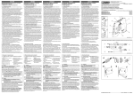
ENGLISH Threshold value switch DEUTSCH Grenzwertschalter 1. Indicazioni di sicurezza 1. Consignes de sécurité 1. Safety notes 1. Sicherheitshinweise 1.1 Note di installazione • L'installazione, l'utilizzo e la manutenzione devono essere eseguiti da personale elettrotecnico qualificato. Seguire le istruzioni di installazione descritte. Rispettare le prescrizioni e le norme di sicurezza valide per l'installazione e l'utilizzo (norme di sicurezza nazionali incluse), nonché le regole tecniche generalmente riconosciute. I dati tecnici di sicurezza sono riportati in questa documentazione allegata e nei certificati (valutazione di conformità ed eventuali ulteriori omologazioni). • Non è consentito aprire o modificare l'apparecchio. Non riparare l'apparecchio da sé, ma sostituirlo con un apparecchio equivalente. Le riparazioni possono essere effettuate soltanto dal produttore. Il produttore non è responsabile per danni in caso di trasgressione. • Il grado di protezione IP20 (IEC 60529/EN 60529) dell'apparecchio è previsto per un ambiente pulito e asciutto. Non sottoporre l'apparecchio ad alcuna sollecitazione meccanica e/o termica che superi le soglie indicate. • Il dispositivo non è concepito per l'impiego in atmosfere a rischio di esplosione. • Durante l'installazione impiegare una custodia idonea del grado di protezione minimo IP54. • L'innesto / disinnesto del connettore bus per guide di montaggio e lo scollegamento dei cavi è consentito soltanto in assenza di tensione. • Mettere fuori servizio il dispositivo se danneggiato, oppure sottoposto a carico non conforme o non conformemente conservato, oppure se presenta difetti funzionali. 1.1 Instructions d'installation • L’installation, l’utilisation et la maintenance doivent être confiées à un personnel spécialisé dûment qualifié en électrotechnique. Respecter les instructions d'installation. Lors de l’exécution et de l’exploitation, respecter les dispositions et normes de sécurité en vigueur (ainsi que les normes de sécurité nationales) de même que les règles généralement reconnues relatives à la technique. Les caractéristiques relatives à la sécurité se trouvent dans ces instructions et les certificats joints (attestation de conformité, autres homologations éventuelles). • L'ouverture ou la transformation de l'appareil ne sont pas admissibles. Ne procédez à aucune réparation sur l'appareil, mais remplacez-le par un appareil équivalent. Seul le fabricant est autorisé à effectuer des réparations sur l’appareil. Le fabricant n’est pas responsable des dommages résultant d’infractions à cette règle. • L’indice de protection IP20 (CEI 60529/EN 60529) de l’appareil est valable dans un environnement propre et sec. Ne pas soumettre l’appareil à des sollicitations mécaniques et/ou thermiques dépassant les limites décrites. • L'appareil n'est pas conçu pour une utilisation dans des atmosphères explosibles. • Installer l'appareil dans un boîtier adapté disposant d'un indice minimum de protection IP54. • L'encliquetage et le désencliquetage sur le connecteur sur profilé ou le raccordement et le débranchement des câbles ne sont autorisés qu'avec l'appareil hors tension. • L'appareil doit être mis hors service s'il est endommagé, soumis à une contrainte ou stocké de manière incorrecte, ou bien s'il présente des dysfonctionnements. 1.1 Installation notes • Installation, operation, and maintenance may only be carried out by qualified electricians. Follow the installation instructions as described. When installing and operating the device, the applicable regulations and safety directives (including national safety directives), as well as generally approved technical regulations, must be observed. The safety data is provided in this package slip and on the certificates (conformity assessment, additional approvals where applicable). • The device must not be opened or modified. Do not repair the device yourself, replace it with an equivalent device. Repairs may only be carried out by the manufacturer. The manufacturer is not liable for damage resulting from violation. • The IP20 protection (IEC 60529/EN 60529) of the device is intended for use in a clean and dry environment. The device must not be subject to mechanical strain and/or thermal loads, which exceed the limits described. • This device is not designed for use in potentially explosive atmospheres. • When installing the device, use an appropriate housing with a minimum protection of IP54. • Only snap the device onto or off the DIN rail connectors and connect/disconnect cables when the power is disconnected. • The device must be stopped if it is damaged, has been subjected to an impermissible load, stored incorrectly, or if it malfunctions. 1.1 Errichtungshinweise • Die Installation, Bedienung und Wartung ist von elektrotechnisch qualifiziertem Fachpersonal durchzuführen. Befolgen Sie die beschriebenen Installationsanweisungen. Halten Sie die für das Errichten und Betreiben geltenden Bestimmungen und Sicherheitsvorschriften (auch nationale Sicherheitsvorschriften), sowie die allgemein anerkannten Regeln der Technik ein. Die sicherheitstechnischen Daten sind dieser Packungsbeilage und den Zertifikaten (Konformitätsbewertung, ggf. weitere Approbationen) zu entnehmen. • Öffnen oder Verändern des Gerätes ist nicht zulässig. Reparieren Sie das Gerät nicht selbst, sondern ersetzen Sie es durch ein gleichwertiges Gerät. Reparaturen dürfen nur vom Hersteller vorgenommen werden. Der Hersteller haftet nicht für Schäden aus Zuwiderhandlung. • Die Schutzart IP20 (IEC 60529/EN 60529) des Gerätes ist für eine saubere und trockene Umgebung vorgesehen. Setzen Sie das Gerät keiner mechanischen und/oder thermischen Beanspruchung aus, die die beschriebenen Grenzen überschreitet. • Das Gerät ist nicht für den Einsatz in explosionsgefährdeten Atmosphären ausgelegt. • Setzen Sie bei der Installation ein geeignetes Gehäuse der Mindestschutzart IP54 ein. • Das Auf- und Abrasten auf den Tragschienen-Busverbinder bzw. das Anschließen und das Trennen von Leitungen ist nur im spannungslosen Zustand zulässig. • Das Gerät ist außer Betrieb zu nehmen, wenn es beschädigt ist, unsachgemäß belastet oder gelagert wurde bzw. Fehlfunktionen aufweist. Puede descargarse la documentación actual en www.knick.de. Documenti aggiornati possono essere scaricati all'indirizzo www.knick.de. 2. Descripción resumida 2. Breve descrizione El interruptor para valores límite configurable se emplea para la regulación y la supervisión de señales analógicas normalizadas. En el lado de entrada pueden seleccionarse las señales analógicas normalizadas de 0...10 V o de 0...20 mA. En el lado de salida se encuentra un relé con contacto conmutado de alta calidad con recubrimiento de oro, que puede accionarse en comportamiento de corriente de trabajo y de reposo. Los interruptores DIP accesibles por el lado de la carcasa permiten la configuración de los siguientes parámetros: Señal de entrada, histéresis de conmutación, dirección de actuación (comportamiento de corriente de trabajo y de reposo), retardos de excitación y desexcitación de relés. La soglia di allarme configurabile viene impiegata per la regolazione e il monitoraggio di segnali analogici normalizzati. Sul lato d'ingresso è possibile scegliere i segnali normalizzati 0...10 V o 0... 20 mA. Sul lato d'uscita è presente un relè di qualità con contatto di scambio dorato che può essere attivato in modalità di corrente di lavoro e di riposo. I DIP switch accessibili dal fianco della custodia consentono la configurazione dei seguenti parametri: segnale di ingresso, isteresi di commutazione, direzione di intervento (comportamento con corrente in modalità di lavoro e di riposo), ritardo di eccitazione e diseccitazione del relè. 3. Indicazioni sui collegamenti 3. Observaciones para la conexión Tome las medidas de protección contra descarga electrostática! 3.1 Elementos de operación () 1 2 3 4 5 6 7 8 9 10 Salida de relé Cubierta LED amarillo: indicación de diagnóstico y estado LED rojo: mensajes de error Potenciómetro para el ajuste de los umbrales de conmutación Ranura para tira Zack ZBF 6 Entrada: señales normalizadas Tensión de alimentación Pie de encaje universal para carriles simétricos EN Interruptor DIP S1 3.2 Instalación El esquema de conjunto muestra la ocupación de los bornes de conexión. () El equipo deberá encajarse sobre todos los carriles de 35 mm según EN 60715. () Prendere misure di protezione adatte per impedire le scariche elettrostatiche! Les documents actuels peuvent être téléchargés à l'adresse www.knick.de. 2. Brève description La bascule double seuil configurable est utilisée pour régler et pour surveiller des signaux normalisés analogiques. Côté entrée, les signaux normalisés disponibles sont 0...10 V et 0...20 mA. Côté sortie, un relais inverseur haut de gamme plaqué or peut fonctionner en mode courant travail et en mode courant repos. Les sélecteurs de codage (DIP) accessibles sur le côté du boîtier permettent de configurer les paramètres suivants : Signal d'entrée, hystérésis de commutation, sens d'action (comportement en mode courant travail ou courant repos), temporisation d'excitation/de retombée du relais. 3. Conseils relatifs au raccordement Prendre des mesures contre les décharges électrostatiques ! 3.1 Elementi di comando () 1 2 3 4 5 6 7 8 9 10 Uscita relè Copertura LED giallo: segnalazione di stato LED rosso: segnalazioni di errore Potenziomentro per l'impostazione delle soglie di commutazione Scanalatura per nastro Zack ZBF 6 Ingresso: segnali normalizzati Tensione di alimentazione Piedino per montaggio universale per guide di supporto EN DIP switch S1 3.2 Installazione Lo schema a blocchi illustra la disposizione dei morsetti di connessione. () Il dispositivo si inserisce a scatto su tutte le guide di supporto da 35 mm a norma EN 60715. () 3.1 Éléments de commande () 1 2 3 4 5 6 7 8 9 10 Sortie de relais Capot LED jaune : voyant d'état LED rouge : messages d'erreur Potentiomètre de réglage des seuils de commutation Rainure pour repérage ZBF 6 Entrée : Signaux normalisés Tension d’alimentation Pied universel encliquetable pour profilés EN Sélecteur de codage (DIP) S1 3.2 Installation L'affectation des bornes de raccordement est illustrée dans le schéma de connexion. () L'appareil s'encliquette sur tous les profilés 35 mm selon EN 60715. () You can download the latest documents from knick.de. 2. Short description The configurable threshold value switch is used to control and monitor analog standard signals. On the input side, the 0...10 V or 0...20 mA standards signals can be selected. A high-quality PDT relay with a gold layer is located on the output side. It can be operated in both operating current and closed circuit current behavior. The DIP switches are accessible on the side of the housing and allow the following parameters to be configured: Input signal, switching hysteresis, operating direction (operating current and closed circuit current behavior), relay pickup/relay dropout delays. 3. Connection notes Take protective measures against electrostatic discharge! 3.1 Operating elements () 1 2 3 4 5 6 7 8 9 10 Relay output Cover Yellow LED: Status indication Red LED: Error messages Potentiometer for setting the switching thresholds Groove for ZBF 6 zack marker strip Input: Standard signals Supply voltage Universal snap-on foot for EN DIN rails DIP switch S1 3.2 Installation The assignment of the connection terminal blocks is shown in the block diagram. () The device can be snapped onto all 35 mm DIN rails according to EN 60715. () Knick Elektronische Messgeräte GmbH & Co. KG Beuckestr. 22, 14163 Berlin, Germany Phone +49 (0)30 - 801 91 - 0, Fax +49 (0)30 - 801 91 - 200 www.knick.de DE EN FR IT ES 2013-11-28 MNR 9064650 Einbauanweisung für den Elektroinstallateur Installation notes for electricians Instructions d'installation pour l'électricien Istruzioni di montaggio per l'elettricista installatore Instrucciones de montaje para el instalador eléctrico Set-Point Alarm Relay BasicLine BL 550 86637 432 6 5 1 8 1 ON S1 F OF = On 7 6 5 lay D e ec 0s c 2 e 1 1s c e 2s c e 3s c e V 4s c In 10 A 4 e m 3 6s c 0 to 20 e 8s c 0 to e sis s re 10 e ste tiv Hy % c A ve it 0.1 % im Acti L h it 1.0 % Hig Lim w 2.5 % Lo 5.0 e d Mo DC V 24 mW r T we 330 PD 1 Po %, 5 t x ±1 Ou ma lay A Re V, 2 0 e 24 in 7 10 Dip 8 2 3 4 In 1.1 Indicaciones de instalación • La instalación, el manejo y el mantenimiento deben ser ejecutados por personal especializado, cualificado en electrotecnia. Siga las instrucciones de instalación descritas. Para la instalación y el manejo, cumpla las disposiciones y normas de seguridad vigentes (también las normas de seguridad nacionales), así como las reglas generales de la técnica. Encontrará los datos técnicos de seguridad en este prospecto y en los certificados (evaluación de conformidad y otras aprobaciones, en caso necesario). • No está permitido abrir o realizar modificaciones en el aparato. No repare el equipo usted mismo, sustitúyalo por otro de características similares. Sólo los fabricantes deben realizar las reparaciones. El fabricante no se hace responsable de los daños derivados del incumplimiento de estas prescripciones. • El tipo de protección IP20 (IEC 60529/EN 60529) del equipo está previsto para un entorno limpio y seco. Detenga el equipo ante cargas mecánicas y/o térmicas que superen los límites descritos. • El dispositivo no está diseñado para su uso en atmósferas con peligro de explosión. • Para la instalación emplee una carcasa adecuada con un grado mínimo de protección IP54. • Solo en estado libre de tensión se permite encajar o extraer el conector T de bus para carril o conectar y separar conductores en un área con peligro de explosión. • Habrá que poner el dispositivo fuera de servicio si está dañado, se ha cargado o guardado inadecuadamente o funciona incorrectamente. Soglia di allarme FRANÇAIS Bascule double seuil Out 1. Advertencias de seguridad ITALIANO 24 V ESPAÑOL Interruptor para valores límite L sic y BaRelaS01 E rm la tA re oin 50 ratu e t-P L 5 8 p Se pe B tem y Ty ting an era °C rm Op +55 Ge in 0 tode 7 Ma 663 8 06 9 Aktuelle Dokumente können Sie unter der Adresse www.knick.de herunterladen. 2. Kurzbeschreibung Der konfigurierbare Grenzwertschalter wird zur Regelung und Überwachung von analogen Normsignalen eingesetzt. Eingangsseitig können Sie die Normsignale 0...10 V oder 0...20 mA wählen. Ausgangsseitig befindet sich ein hochwertiges Wechslerrelais mit Goldbeschichtung, welches im Arbeits- und Ruhestromverhalten betrieben werden kann. Die an der Gehäuseseite zugänglichen DIP-Schalter erlauben die Konfiguration folgender Parameter: Eingangssignal, Schalthysterese, Wirkrichtung (Arbeits- oder Ruhestromverhalten), Relaisanzug- und Abfallverzögerungszeiten. 3. Anschlusshinweise AWG 26-12 0,2-2,5 mm2 B A 12 mm 0,5-0,6 Nm 5-7 lb In Treffen Sie Schutzmaßnahmen gegen elektrostatische Entladung! OUT IN Sensor / Field PLC / DCS 3.1 Bedienelemente () 1 2 3 4 5 6 7 8 9 10 Relaisausgang Abdeckung LED gelb: Statusanzeige LED rot: Fehlermeldungen Potenziometer zum Einstellen der Schaltschwellen Nut für Zackband ZBF 6 Eingang: Normsignale Versorgungsspannung Universal-Rastfuß für EN-Tragschienen DIP-Schalter S1 3.2 Installation Die Belegung der Anschlussklemmen zeigt das Blockschaltbild. () Das Gerät ist auf alle 35-mm-Tragschienen nach EN 60715 aufrastbar. () OUT 5 U,I US + 5 IN U,I 1 4-wire GND 6 – 6 + 7 – 8 GND 1 +24V 2 2 3 3 GND 2 4 4 © Knick 2013 PNR 105697 - 00 DNR 83150540 - 00 ESPAÑOL ITALIANO FRANÇAIS ENGLISH DEUTSCH 4. Configuración () 4. Configurazione () 4. Configuration () 4. Configuration () 4. Konfiguration () 4.1 Interruptor DIP S1 Mediante el microinterruptor DIP S1 es posible predefinir el rango de señales de entrada, la histéresis de conmutación, el retardo de excitación y desexcitación de relés, así como la conmutación del sentido de actuación (véase la tabla). – En la configuración "High Limit Active" (comportamiento de corriente de trabajo), el tiempo de retardo tendrá efecto cuando se sobrepase el umbral de conmutación. La caída por debajo del umbral tiene lugar sin retardo. – En la configuración "Low Limit Active" (comportamiento de corriente de reposo) el tiempo de retardo tendrá efecto cuando se caiga por debajo del umbral de conmutación. El sobrepaso del umbral tiene lugar sin retardo. 4.2 Ajuste de los umbrales de conmutación Debajo de la cubierta se encuentra un potenciómetro con el que es posible ajustar los umbrales de conmutación. • Aplique, p. ej. con una fuente de calibración, el valor de umbral analógico a la entrada de señal. • Con el interruptor DIP S1, ponga en primer lugar la histéresis y el tiempo de retardo a "0" (estado por defecto a la entrega). • Gire el potenciómetro hasta que se apague o encienda el LED amarillo. • Mediante el interruptor DIP S1, active ahora una histéresis o un tiempo de retardo, si así lo desea. 4.1 DIP switch S1 Con il DIP switch S1 viene predefinito il campo dei segnali di ingresso, l'isteresi di commutazione, il ritardo di eccitazione e di diseccitazione del relè nonché la commutazione della direzione di intervento (vedere tabella). – Con l'impostazione "High Limit Active" (comportamento della corrente di lavoro), il tempo di ritardo si attiva al superamento della soglia di commutazione. In caso di mancato raggiungimento della soglia, la commutazione avviene senza ritardo. – Con l'impostazione "Low Limit Active" (comportamento della corrente di lavoro), il tempo di ritardo si attiva al mancato raggiungimento della soglia di commutazione. In caso di superamento della soglia, la commutazione avviene senza ritardo. 4.2 Impostazione delle soglie di commutazione Sotto alla copertura è presente un potenziometro che permette di eseguire l'impostazione delle soglie di commutazione. • Assegnare, ad esempio con una fonte di calibrazione, il valore di soglia analogico all'ingresso del segnale. • Commutare innanzitutto con il DIP switch S1 l'isteresi e il tempo di ritardo su "0" (stato alla consegna). • Ruotare il potenziometro fino a che non si accende o non si spegne il LED giallo. • Attivare ora, se lo si desidera, con il DIP switch S1 una isteresi o un tempo di ritardo. 4.1 Sélecteur de codage (DIP) S1 Le sélecteur de codage (DIP) S1 vous permet de définir la plage de signal d'entrée, l'hystérésis de commutation, la temporisation d'excitation/de retombée du relais ainsi que la commutation du sens d'action (voir le tableau). – Lorsque le réglage est « High Limit Active » (mode courant travail), la temporisation s'active après dépassement du seuil de commutation. Le sous-dépassement du seuil n'est pas temporisé. – Lorsque le réglage est «Low Limit Active » (mode courant repos), la temporisation s'active après sous-dépassement du seuil de commutation. Le dépassement du seuil n'est pas temporisé. 4.2 Réglage des seuils de commutation Le potentiomètre permettant le réglage des seuils de commutation se trouve sous le capot. • En utilisant par exemple une source de calibrage, définir la valeur analogique du seuil destinée à l'entrée du signal. • Avec le sélecteur de codage (DIP) S1, régler tout d'abord l'hystérésis et la temporisation sur « 0 » (état à la livraison). • Tourner le potentiomètre correspondant jusqu'à ce que la LED jaune s'allume ou s'éteigne. • Activer ensuite une hystérésis ou une temporisation à l'aide du sélecteur de codage (DIP) S1, en fonction des besoins. 4.1 DIP switch S1 DIP switch S1 can be used to specify the input signal range, the switching hysteresis, and the relay pickup/relay dropout delay, and to switch the operating direction (see the table). – With the setting "High Limit Active" (operating current behavior), the delay time takes effect following the exceedance of the switching threshold. There is no delay time for the undershooting of the threshold. – With the setting "Low Limit Active" (closed circuit current behavior), the delay time takes effect following the undershooting of the switching threshold. There is no delay time for the exceeding of the threshold. 4.2 Setting the switching thresholds A potentiometer which is used to set the switching thresholds is located underneath the cover. • Apply the analog threshold to the signal input using, for example, a calibration source. • First, set the hysteresis and the delay time to "0" (delivery state) using DIP switch S1. • Adjust the potentiometer until the yellow LED lights up or extinguishes. • Now activate a hysteresis or delay time using DIP switch S1, if required. 4.1 DIP-Schalter S1 Mit dem DIP-Schalter S1 geben Sie den Eingangssignalbereich, die Schalthysterese, die Relaisanzug- und Abfallverzögerungszeit sowie die Umschaltung der Wirkrichtung vor (siehe Tabelle). – In der Einstellung "High Limit Active" (Arbeitsstromverhalten) wird die Verzögerungszeit nach Überschreiten der Schaltschwelle wirksam. Das Unterschreiten der Schwelle erfolgt unverzögert. – In der Einstellung "Low Limit Active" (Ruhestromverhalten) wird die Verzögerungszeit nach Unterschreiten der Schaltschwelle wirksam. Das Überschreiten der Schwelle erfolgt unverzögert. 4.2 Einstellung der Schaltschwellen Unter der Abdeckung befindet sich ein Potenziometer, mit dem Sie die Schaltschwellen einstellen können. • Legen Sie z.B. mit einer Kalibrierquelle den analogen Schwellwert an den Signaleingang an. • Schalten Sie zunächst mit dem DIP-Schalter S1 die Hysterese wie auch die Verzögerungszeit auf "0" (Auslieferungszustand). • Drehen Sie am Potenziometer, bis die gelbe LED aufleuchtet bzw. erlischt. • Aktivieren Sie nun mit dem DIP-Schalter S1 eine Hysterese oder Verzögerungszeit, falls gewünscht. 5. Voyant de diagnostic The yellow LED on the front of the device indicates that voltage is being applied to the PDT relay coil, i.e., that the relay has switched. The red LED which is visible on the front displays the following faults: – LED ON: Measured value (overrange) > 102.5% – LED flashing: Module faulty 5. Indicación de diagnóstico El LED amarillo visible en la parte frontal señaliza que la bobina del relé con contacto conmutado está bajo tensión, es decir, que el relé se ha activado. El LED rojo visible en la parte frontal indica los siguientes estados de fallo: – LED encendido: Superación del rango de medición (Overrange) > 102,5 % – LED parpadeante: Módulo averiado Il LED giallo visibile frontalmente segnala che la bobina del relè con contatto di scambio è alimentata, ossia che il relè è attivato. Il LED rosso visibile frontalmente indica i seguenti stati di errore: – LED lampeggiante: superamento per eccesso del campo di misura (overrange) > 102,5 % – LED lampeggiante: modulo difettoso La LED jaune située sur la face avant indique que la bobine du relais inverseur est sous tension, c'est à dire que le relais est activé. La LED rouge située sur la face avant indique les défauts suivants : – LED allumée : dépassement de la plage de mesure (Overrange) > 102,5 % – La LED clignote : module défectueux 6. Garantía 6. Garanzia 6. Garantie Las carencias que se presenten dentro de un plazo de 3 años se subsanarán gratuitamente en fábrica bajo envío libre de portes. I danni che si verificano entro 3 anni vengono eliminati gratuitamente se il dispositivo viene inviato allo stabilimento a proprie spese. Les défauts survenus en l'espace de trois années sont éliminés en usine gratuitement si vous effectuez l'envoi à vos propres frais. 5. Visualizzazione diagnostica 5. Diagnostic indicator 6. Warranty Die frontseitig sichtbare gelbe LED signalisiert, dass die Spule des Wechslerrelais mit Spannung beaufschlagt ist, d. h. dass das Relais geschaltet hat. Die frontseitig sichtbare rote LED zeigt folgende Fehlerzustände an: – LED leuchtet: Messbereichsüberschreitung (Overrange) > 102,5 % – LED blinkt: Modul defekt Defects that occur within three (3) years are rectified at the factory in the case of goods delivered to the factory. 6. Garantie Dati tecnici Caractéristiques techniques Technical data Technische Daten Collegamento Dati d'ingresso Segnale d'ingresso Segnale d'ingresso massimo Resistenza d'ingresso Uscita ON-OFF Uscita relè Esecuzione dei contatti 1 di scambio Materiale dei contatti AgSnO2, dorato a spessore Max. tensione di commutazione Max. corrente istantanea Max. corrente istantanea Isteresi interna (configurabile tramite DIP switch) Type de raccordement Données d'entrée Signal d'entrée Signal d'entrée maximum Impédance d'entrée Sortie de couplage Sortie à relais Type de contact 1 inverseur Matériau des contacts AgSnO2, doré Tension de commutation max. Courant de commutation max. Courant de commutation max. Hystérésis interne (configurable via commutateur DIP) Plage de réglage de la temporisation du temps d'amorçage (configurable via commutateur DIP) Sens d'action (Mode courant travail/repos) commutable avec les commutateurs DIP Connection method Input data Input signal Maximum input signal Input resistance Switching output Relay output Contact type 1 PDT Contact material AgSnO2, hard gold-plated Max. switching voltage Max. switching current Max. switching current Internal hysteresis (configurable using the DIP switch) Setting range of the response delay (configurable using the DIP switch) Operating direction (Operating and closed circuit current behavior) Switchable using DIP switch Anschlussart Eingangsdaten Eingangssignal Maximales Eingangssignal Eingangswiderstand Schaltausgang Relaisausgang Kontaktausführung 1 Wechsler Kontaktmaterial AgSnO2, hartvergoldet Max. Schaltspannung Max. Schaltstrom Max. Schaltstrom Interne Hysterese (konfigurierbar über DIP-Schalter) Caractéristiques générales Tension d'alimentation UB Courant absorbé Consommation de puissance Coefficient de température max. Précision point de commutation Reproductibilité General data Supply voltage UB Current consumption at 24 V DC Power consumption at 24 V DC Maximum temperature coefficient Switching point accuracy Repeat accuracy Allgemeine Daten Versorgungsspannung UB Stromaufnahme bei 24 V DC Leistungsaufnahme bei 24 V DC Temperaturkoeffizient maximal Schaltpunktgenauigkeit Wiederholgenauigkeit Réponse indicielle (0 - 99 %) Indice de protection Plage de température ambiante Exploitation Stockage/transport Dimensions l / H / P Isolation galvanique Isolation de base selon EN 61010 Catégorie de surtension Degré de pollution Tension d'isolement assignée Tension d'essai entrée/alimentation Conformité / Homologations UL, USA/Canada Conformité à la directive CEM 2004/108/CE Emission selon Immunité De faibles écarts peuvent survenir lors de perturbations. Step response (0–99%) Degree of protection Ambient temperature range Operation Storage/transport Dimensions W / H / D Electrical isolation Basic insulation according to EN 61010 Surge voltage category Pollution degree Rated insulation voltage Test voltage input/power supply Conformance / approvals UL, USA / Canada Conformance with EMC Directive 2004/108/EC Noise emission according to Noise immunityWhen being exposed to interference, there may be minimal deviations. Sprungantwort (0-99%) Schutzart Umgebungstemperaturbereich Betrieb Lagerung/Transport Abmessungen B / H / T Galvanische Trennung Basisisolierung nach EN 61010 Überspannungskategorie Verschmutzungsgrad Bemessungsisolationsspannung Prüfspannung Eingang/Versorgung Konformität / Zulassungen UL, USA / Kanada Konformität zur EMV-Richtlinie 2004/108/EG Störabstrahlung nach Störfestigkeit Während der Störbeeinflussung kann es zu geringen Abweichungen kommen. pour 24 V DC pour 24 V DC Hysteresis Delay Mode Innerhalb von 3 Jahren auftretende Mängel werden bei freier Anlieferung im Werk kostenlos behoben. Datos técnicos Dati generali Tensione di alimentazione UB Corrente assorbita con 24 V DC Potenza assorbita con 24 V DC Coefficiente termico massimo Precisione punto di inserzione Precisione di ripetizione Tempo di risposta (0-99%) Grado di protezione Range temperature Funzionamento Immagazzinamento/trasporto Dimensioni L / A / P Isolamento galvanico Isolamento base a norma EN 61010 Categoria di sovratensione Grado d'inquinamento Tensione di isolamento nominale Tensione di prova ingresso/alimentazione Conformità/omologazioni UL, USA / Canada Conformità alla direttiva EMC 2004/108/CE Emissione disturbi a norma Immunità ai disturbiLe interferenze possono causare leggeri scostamenti. ON = IN 5. Diagnoseanzeige Tipo de conexión Datos de entrada Señal de entrada Señal máxima de entrada Resistencia de entrada Salida de conmutación Salida de relé Tipo de contacto 1 contacto conmutado Material del contacto AgSnO2, dorado duro Tensión de activación máx. Corriente máx. de conmutación Corriente máx. de conmutación Histéresis interna (Configurable a través de interruptor DIP) Margen de ajuste del retardo de reacción (Configurable a través de interruptor DIP) Sentido de actuación (Comportamiento de corriente de trabajo y de reposo) Conmutable a través de interruptor DIP Datos generales Tensión de alimentación UB Absorción de corriente con 24 V DC Consumo de potencia con 24 V DC Coeficiente de temperatura máximo Precisión de los puntos de conmutación Precisión de repetición Respuesta gradual (0-99 %) Índice de protección Margen de temperatura ambiente Funcionamiento Almacenamiento/transporte Dimensiones An. / Al. / Pr. Separación galvánica Aislamiento básico según EN 61010 Categoría de sobretensiones Grado de polución Tensión de aislamiento de dimensionamiento Tensión de prueba Entrada/alimentación Conformidad / Homologaciones UL, EE.UU. / Canadá Conformidad con la directiva CEM 2004/108/CE Emisión de interferencias según Resistencia a interferencias Durante las interferencias pueden producirse ligeras desviaciones. Campo di regolazione del ritardo di risposta (configurabile tramite DIP switch) Direzione di intervento (Modalità corrente di lavoro e di riposo) invertibile tramite DIP switch Einstellbereich der Ansprechverzögerung (konfigurierbar über DIP-Schalter) Wirkrichtung (Arbeits- und Ruhestromverhalten) umschaltbar über DIP-Schalter Set-Point Alarm Relay BasicLine BL 550 86637 I U 0 mA ... 20 mA 0 V ... 10 V 100 mA 30 V 50 Ω 100 kΩ 240 V AC 2A (0,1 %; 1 %; 2,5 %; 5 %) 0 s ... 10 s (0 s; 1 s; 2 s; 3 s; 4 s; 6 s; 8 s; 10 s) 24 V DC ± 15 % < 14 mA < 330 mW < 0,02 %/K < 0,2 % < 35 ms IP20 0 °C ... 55 °C -40 °C ... 85 °C 6,2 mm / 93,1 mm / 102,5 mm II 2 50 V AC/DC 1,5 kV AC (50 Hz, 1 min.) UL 508 Recognized EN 61000-6-4 EN 61000-6-2 © Knick 2013 0 ... 10 V 0 ... 20 mA 0.1 % 1.0 % 2.5 % 5.0 % 0 sec 1 sec 2 sec 3 sec 4 sec 6 sec 8 sec 10 sec High limit active Low limit active DIP S1 1 2 3 4 5 6 7 8 1. 安全提示 1. Правила техники безопасности 1. Güvenlik notları 1. Instruções de segurança 1.1 安装注意事项 • 仅专业电气人员可进行相关安装、操作和维修。请按说明遵守安装规定。安装 与操作设备时,必须遵守适用的规定和安全规范 (包括国家安全规则)以及普 遍认可的技术总则。相关安全数据附于包装单内和认证中 (所适用的一致性评 估与附加认证)。 • 设备不可打开或改造。 请勿自行修理设备,可更换整部设备。 仅生产厂家可进 行修理。 生产厂家对因滥用产品而导致的损坏不负责任。 • 该设备的 IP20 防护等级 (IEC 60529/EN 60529) 适用于清洁而干燥的环境。 该设备可能不适用于超过所规定限制的机械应力与 / 或热负荷。 • 本设备的设计不适用于易爆气体环境。 • 安装设备时,要使用保护等级至少为 IP54 的合适外壳。 • 在断开电源的情况下,只需要将设备卡接到 DIN 导轨连接器上或将其取下,并 连接 / 断开电缆。 • 在设备损坏、达到不允许的负载、存储不当或功能失灵时必须将其停止。 1.1 инструкции по монтажу • Монтаж, управление и работы по техобслуживанию разрешается выполнять только квалифицированным специалистам по электротехническому оборудованию. Следовать описанным указаниям по монтажу. При установке и эксплуатации соблюдайте действующие инструкции и правила техники безопасности (в том числе и национальные предписания по технике безопасности), а также общетехнические правила. Сведения о безопасности содержатся в данной инструкции и сертификатах (сертификат об оценке соответствия, при необходимости дополнительные сертификаты). • Запрещается открывать или модифицировать устройство. Не ремонтируйте устройство самостоятельно, а замените его на равноценное устройство. Ремонт должен производиться только сотрудниками компании-изготовителя. Производитель не несет ответственности за повреждения вследствие несоблюдения предписаний. • Степень защиты IP20 (IEC 60529/EN 60529) устройства предусматривает использование в условиях чистой и сухой среды. Не подвергайте устройство механическим и/или термическим нагрузкам, превышающим указанные предельные значения. • Устройство не рассчитано на применение в зонах с взрывоопасной атмосферой. • При монтаже используйте подходящий корпус со степенью защиты не менее IP54. • Установка на шинный соединитель, устанавливаемый на монтажную рейку, и демонтаж с него или подключение и отключение проводов допустимы только в обесточенном состоянии. • В случае повреждения, неправильной нагрузки или хранения или ненадлежащей работы устройства, оно должно быть изъято из эксплуатации. 1.1 Montaj talimatları • Montaj, işletme ve bakım yalnız yetkin elektrik personeli tarafından yapılmalıdır. Belirtilen montaj talimatlarına uyun. Cihazı kurarken ve çalıştırırken geçerli güvenlik yönetmelikleri (ulusal güvenlik yönetmelikleri dahil) ve genel teknik yönetmelikler gözetilmelidir. Teknik güvenlik verileri paket içeriğinde ve sertifika üzerinde verilmektedir (uygunluk belgesi, gerekli durumlarda ek onaylar). • Cihaz açılmamalı veya değiştirilmemelidir. Cihazı kendiniz tamir etmeyin, aynısıyla değiştirin. Onarımlar sadece üretici tarafından yapılır. Üretici kurallara aykırı kullanımdan kaynaklanan hasardan sorumlu değildir. • Cihazın IP20 koruması (IEC 60529/EN 60529) temiz ve kuru ortam için tasarlanmıştır. Cihaz tanımlanan limitlerin üzerinde mekanik zorlanma ve/veya termal yüklere maruz kalmamalıdır. • Bu cihaz patlama riskli ortamlarda kullanıma uygun tasarlanmamıştır. • Bu cihazı monte ederken minimum IP54 koruma sınıfına sahip uygun bir muhafaza kullanın. • Cihazı sadece DIN ray konnektörlerine takın veya çıkartın ve kabloları bağlayıp/ ayırırken elektrik bağlantısını kesin. • Hasarlı olan, izin verilmeyen bir şekilde yüklenen, yanlış depolanan veya hatalı olarak çalışan cihaz durdurulmalıdır. 1.1 instruções de montagem • A instalação, operação e manutenção devem ser executadas por pessoal eletrotécnico qualificado. Siga as instruções de instalação descritas. Observar a legislação e as normas de segurança vigentes para a instalação e operação (inclusive normas de segurança nacionais), bem como as regras técnicas gerais. Os dados técnicos de segurança devem ser consultados neste folheto e nos certificados (avaliação da conformidade e, se necessário, outras certificações). • Não é permitido abrir ou alterar o equipamento. Não realize manutenção no equipamento, apenas substitua por um equipamento equivalente. Consertos somente podem ser efetuados pelo fabricante. O fabricante não se responsabiliza por danos decorrentes de violação. • O grau de proteção IP20 (IEC 60529 / EN 60529) do equipamento destina-se a um ambiente limpo e seco. Não submeta o equipamento a cargas mecânicas e/ ou térmicas, que excedam os limites descritos. • O equipamento não foi projetado para a utilização em atmosferas com perigo de explosão. • Usar para a instalação uma caixa com grau de proteção mínimo de IP54. • Encaixar no e separar do conector de barramento do trilho de fixação e a ligação e separação de condutores apenas são admissíveis no estado livre de tensão. • O equipamento deve ser colocado fora de operação se estiver danificado, se foi sujeito a carga ou armazenagem incorretas ou se exibir uma falha de função. 2. 概述 可组态阈值开关用于控制和监控标准模拟量信号。 可在输入侧选择 0...10 V 或 0...20 mA 标准信号。 输出侧是高品质的镀金 PDT 继电器。可在工作电流和闭合电路电流两种形式下运 行。 可通过外壳侧面的 DIP 开关对以下参数进行设置: 输入信号、开关滞后、运行方向 (工作电流和闭路电流特性)、继电器吸合 / 继 电器脱扣延迟。 3. 连接注意事项 请采取保护措施以防静电释放! 3.1 操作元件 () 1 2 3 4 5 6 7 8 9 10 继电器输出 盖板 黄色发光二极管:状态指示 红色发光二极管:错误信息 用于设置开关阈值的电位计 用于 ZBF 6 扁平式标记条的标记槽 输入:标准信号 供电电源 用于 EN DIN 导轨的通用卡接支脚 DIP 开关 S1 3.2 安装 接线图中显示接线端子的分配。() 可以卡接到符合 EN60715 标准的 35mm DIN 导轨上。() Актуальную документацию Вы можете скачать по адресу www.knick.de. 2. Краткое описание Конфигурируемое реле предельного значения предназначено для регулирования и контроля аналоговых нормированных сигналов. На входе возможен выбор диапазона нормированных сигналов 0...10 В или 0...20 мА. На стороне выхода имеется высококачественное реле с переключающим контактом, имеющим золотое покрытие. Реле может работать на выбор: на рабочем токе или на токе покоя. С помощью установленных на корпусе DIP-переключателей производится настройка следующих параметров: входного сигнала, гистерезиса переключения, направления действия, (рабочий ток или ток покоя), времени задержки притяжения и отпадания реле. 3. Указания по подключению Должны быть предприняты меры по защите от электростатических разрядов! 3.1 Органы управления () 1 2 3 4 5 6 7 8 9 10 Релейный выход Крышка Желтый светодиод: Индикатор состояния Красный светодиод: Сообщения об ошибках Потенциометр для настройки пороговых значенийПотенциометр для настройки пороговых значений Паз для планки Zack ZBF 6 Вход: Нормированные сигналы Электропитание Универсальное монтажное основание с защелками, для рейки ENтипа DIP-переключатель S1 3.2 Монтаж На блок-схеме показано назначение выводов клемм. () Блок питания устанавливается на защелках на любые DIN-рейки 35 мм, соотв. EN 60715. () En son dokümanları knick.de adresinden yükleyebilirsiniz. 2. Kısa tanım Konfigüre edilebilir eşik değer anahtarı standart analog sinyallerin kontrolü ve izlenmesinde kullanılır. Giriş tarafında, 0...10 V veya 0...20 mA standart sinyalleri seçilebilir. Altın katmanlı yüksek kaliteli PDT röle çıkış tarafında bulunur. Bu röle hem çalışma akımında hem de kapalı devre akım karakteristiğinde çalıştırılabilir. DIP siviçlere kutunun yan tarafından erişilebilir ve şu parametrelerin konfigüre edilmesini sağlar: Giriş sinyali, anahtarlama histerileri, çalışma yönü (çalışma akımı ve kapalı devre davranışı), röle pikap/kesme rölesi gecikmeleri. 3. Bağlantı talimatları Elektrostatik boşalmaya karşı gerekli önlemleri alın! 3.1 Çalışma elemanları () 1 2 3 4 5 6 7 8 9 10 Röle çıkışı Kapak Sarı LED: Durum göstergesi Kırmızı LED: Hata mesajları Anahtarlama eşiklerinin ayarlanması için potansiyometre ZBF 6 etiket şeridi için yiv Giriş: Standart sinyaller Besleme gerilimi EN DIN rayları için üniversal geçmeli ayak DIP anahtar S1 3.2 Montaj Bağlantı termina bloklarının ataması, blok şemasında gösterilmiştir. () Cihaz EN 60715'e uygun tüm 35 mm DIN raylarına takılabilir. () Knick Elektronische Messgeräte GmbH & Co. KG Beuckestr. 22, 14163 Berlin, Germany Phone +49 (0)30 - 801 91 - 0, Fax +49 (0)30 - 801 91 - 200 www.knick.de PT TR RU ZH 2013-11-28 MNR 9064650 Instrução de montagem para o eletricista Elektrik personeli için montaj talimatı Инструкция по установке для электромонтажника 电气人员安装须知 Set-Point Alarm Relay BasicLine BL 550 86637 432 6 5 1 8 1 ON S1 F OF = On 7 6 5 lay D e ec 0s c e 1s c e 2s c e 3s c e 4s c 4 e s 3 6 c e 8s c e s 10 ve ti Ac it tive c im L A h it Hig Lim w Lo 1 7 V In 10 A m 0 to 20 0 to sis re ste Hy % 0.1 % 1.0 % .5 2 % 5.0 de Mo DC V 24 mW r T we 330 PD 1 Po %, 5 t x ±1 Ou ma lay 2 A e , R V 0 e 24 É possível efetuar o download dos documentos atuais em www.knick.de. 10 2 Dip 8 2 3 4 In Eşik değer anahtarı PORTUGUÊSE Chave de valor limite 您可以从 knick.de 下下载最新文档。 TÜRKÇE Out 阈值开关 РУССКИЙ Реле предельного значения 24 V 中文 Lin 2. Descrição breve O interruptor configurável de valores limite é usado para a regulação e supervisão de sinais analógicos normalizados. Do lado de entrada podem ser selecionados os sinais normalizados 0...10 V ou 0...20 mA. No lado de saída encontra-se um relé de inversor de alta qualidade com camada de ouro que pode ser operado no comportamento de trabalho e de corrente de repouso. As chaves DIP acessíveis na lateral da caixa permitem a configuração dos seguintes parâmetros: Sinal de entrada, histerese de comutação, direção de ação (comportamento como circuito normalmente fechado ou aberto), tempos de armar e desarmar do relé. sic y BaRelaS01 E rm la tA re oin 550 ratu e t-P 8 L p Se pe B tem y Ty ting an era °C rm Op +55 Ge in 0 tode 7 Ma 663 8 B Tomar medidas de protecção contra descargas electrostáticas! 3.1 Elementos de operação () Saída de relé Tampa LED amarelo: Indicação de estado LED vermelho: Mensagens de erro Potenciômetro para ajustar os limiares de comutação Ranhura para tiras de fitas dentadas ZBF 6 Entrada: Sinais normalizados Tensão de alimentação Pé de encaixe universal para trilhos de fixação conforme EN Chave DIP S1 9 AWG 26-12 0,2-2,5 mm2 3. Instruções de conexão 1 2 3 4 5 6 7 8 9 10 06 A 12 mm 0,5-0,6 Nm 5-7 lb In OUT 5 U,I US 3.2 Instalação A atribuição dos bornes é mostrada no esquema de blocos. () O aparelho é encaixável em todos os trilhos de fixação de 35 mm de acordo com EN 60715. () OUT IN Sensor / Field + 5 IN U,I PLC / DCS 1 4-wire GND 6 – 6 + 7 – 8 GND 1 +24V 2 2 3 3 GND 2 4 4 © Knick 2013 PNR 105697 - 00 DNR 83150540 - 00 中文 РУССКИЙ TÜRKÇE PORTUGUÊSE 4. 组态 () 4. Конфигурация () 4. Konfigürasyon () 4. Configuração () 4.1 DIP 开关 S1 DIP 开关 S1 可用于规定输入信号范围、开关滞后和继电器吸合 / 继电器脱扣延 迟以及切换运行方向 (参见表格)。 – 如果设置为 “High Limit Active” (工作电流特性),延迟时间会在超过切换阈 值后生效。低于阈值时没有延迟时间。 – 如果设置为 “Low Limit Active” (闭路电流特性),延迟时间会在低于切换阈值 后生效。高于阈值时没有延迟时间。 4.2 设置开关阈值 用于设置开关阈值的电位计位于罩盖之下。 • 使用例如校准源对信号输入应用模拟量阈值。 • 首先用 DIP 开关 S1 将滞后和延迟时间设为 “0” (供货状态)。 • 调节电位计直到黄色发光二极管亮起或熄灭。 • 如果需要,则此时用 DIP 开关 S1 激活滞后或延迟时间。 4.1 DIP-переключатель S1 При помощи DIP-переключателя S1 Вы можете задать диапазон входных сигналов, гистерезис переключения, время задержки притяжения и отпадания реле, а также переключение направления действия (см. таблицу). – При настройке "High Limit Active" (рабочий ток) время задержки включается после превышения порога срабатывания. Падение ниже порога происходит без задержки. – При настройке "Low Limit Active" (ток покоя) время задержки включается после падения ниже порога срабатывания. Превышение порога происходит без задержки. 4.2 Настройка пороговых значений срабатывания Под крышкой находится потенциометр, с помощью которого можно установить пороговые значения срабатывания. • С помощью калибровочного источника задать, например, аналоговое пороговое значение для сигнального входа. • Сначала DIP-переключателем S1 установить гистерезис и время задержки на "0" (состояние поставки). • Поворачивать потенциометр до тех пор, пока не загорится или погаснет желтый светодиод. • Если необходимо, DIP-переключателем S1 активировать гистерезис или время задержки. 4.1 DIP anahtar S1 DIP anahtar S1 giriş sinyali aralığını, anahtarlama histerisini ve röle pikap/röle kesilme gecikmesini belirlemek ve çalışma yönünü değiştirmek için kullanılabilir (tabloya bakınız). – "Yüksek Limit Aktif" ayarı ile (çalışma akımı davranışı), anahtarlama eşik değeri geçildiğinde gecikme süresi etkinleşir. Eşik değerin altına düşülmesi için bir gecikme süresi mevcut değildir. – "Düşük Limit Aktif" ayarı ile (kapalı devre akımı davranışı), anahtarlama eşik değeri altına düşüldüğünde gecikme süresi etkinleşir. Eşik değerin geçilmesi için bir gecikme süresi mevcut değildir. 4.2 Anahtarlama eşiklerinin ayarlanması Anahtarlama eşiklerini ayarlamaya yarayan potansiyometre kapağın altındadır. • Örneğin, bir kalibrasyon kaynağı yardımıyla sinyal girişine analog eşik uygulayın. • Öncelikle, S1 DIP anahtarını kullanarak histerezis ve gecikme zamanını "0" durumuna (teslimat durumu) getirin. • Sarı LED yanana veya sönene kadar potansiyometreyi ayarlayın. • Şimdi de, gerekiyorsa, S1 DIP anahtarını kullanarak bir histerezis veya gecikme zamanını etkinleştirin. 4.1 Chave DIP S1 Com a chave DIP S1 define-se a faixa do sinal de entrada, a histerese de comutação, o tempo de armar e desarmar do relé bem como a comutação da direção de ação (veja tabela). – No ajuste "High Limit Active" (princípio de circuito fechado), o tempo de retardo após ultrapassar o limiar de comutação é aplicado. Se passar para baixo do limiar, não há retardo. – No ajuste "Low Limit Active" (princípio de circuito aberto), o tempo de retardo após passar o limiar de comutação para baixo é aplicado. Se ultrapassar o limiar, não há retardo. 4.2 Ajuste dos limiares de comutação Abaixo da tampa há um potenciômetro com o qual os limiares de comutação podem ser ajustados. • Ligar o valor de limiar analógico à entrada de sinal mediante, p.ex., uma fonte de calibração. • Primeiramente, comutar com ajuda da chave DIP S1 a histerese bem como o tempo de retardo para "0" (estado de fornecimento). • Girar no potenciômetro até o LED amarelo acender ou se apagar. • Agora, ativar mediante a chave DIP S1 uma histerese ou um tempo de retardo, caso desejado. 5. 诊断指示 在设备前部的黄色发光二极管表示 PDT 继电器线圈有电压,即继电器已接通。 前部的红色发光二极管表示以下错误: – 发光二极管亮起:测量值 (测量值上溢)> 102.5% – 发光二极管闪烁:模块错误 6. 保修 若三 (3)年内发生故障,则在产品被送返工厂的情况下,在工厂内进行修理。 5. Диагностический индикатор Видимый на передней панели желтый светодиод сигнализирует, что на катушку реле с переключающим контактом подается напряжение, то есть реле включилось. Видимый на передней панели красный светодиод отображает следующие аварийные состояния: – Светодиод горит: Выход за верхнюю границу измерительного диапазона (Overrange) > 102,5 % – Светодиод мигает: неисправный модуль 5. Diyagnostik gösterge Cihazın ön kısmındaki sarı LED PDT röle bobinine gerilim uygulandığını, yani rölenin anahtarlandığını gösterir. Ön taraftan görülebilen kırmızı LED aşağıdaki hataları görüntüler: – LED YANIYOR: Ölçülen değer (aralığın üzerinde) > %102.5 – LED yanıp sönüyör: Modül arızalı ON = IN Hysteresis Delay Mode 5. Indicação de diagnóstico 6. Garanti O LED amarelo visível na parte frontal assinala que a bobina do relé do conversor está energizada, ou seja, que o relé armou. O LED vermelho visível na parte frontal indica os seguintes estados de falha: – LED aceso: faixa de medição ultrapassada (Overrange) > 102,5 % – LED piscando: módulo com defeito Ürünler fabrikaya teslim edildiğinde, üç (3) yıl içerisinde oluşan arızalar fabrikada düzeltilir. 6. Garantia Falhas que incidam dentro de 3 anos são eliminadas na fábrica sem custo com frete por conta do cliente. 6. Гарантия Проявляющиеся в течение 3 лет дефекты устраняются бесплатно при свободной поставке на завод. 接线方式 输入数据 输入信号 最大输入信号 输入阻抗 开关输出 触点类型 触点材料 最大切换电压 最大开关电流 最大开关电流 内置滞后 响应延迟的设置范围 技术数据 Технические характеристики 继电器输出 1PDT AgSnO2,镀硬质金 (使用 DIP 开关可进行组态) (使用 DIP 开关可进行组态) 运行方向 ( 工作和闭合电路的电流动作 ) 可用 DIP 开关进行控制 般参数 电源电压 UB 耗用电流 功耗 最大温度系数 切换点精度 24 V DC 24 V DC 中继精度 阶跃响应 (0-99%) 保护等级 环境温度范围 操作 存储 / 运输 尺寸 宽度 / 高度 / 深度 电气隔离 符合 EN 61010 的基础隔离 浪涌电压类别 污染等级 额定绝缘电压 测试电压输入/电源 符合性/认证 UL,美国/加拿大 符合 EMC 条例 2004/108/EC 发射干扰 符合 抗干扰 受到干扰时,那有可能是最小的偏差。 Тип подключения Входные данные Входной сигнал Максимальный входной сигнал Входное сопротивление Выходной переключающий контакт Выход для реле Исполнение контакта 1 переключающий контакт Материал контакта AgSnO2, твердое золочение Макс. коммутационное напряжение Макс. коммутационный ток Макс. коммутационный ток Внутренний гистерезис (настраивается DIPпереключателем) Диапазон настройки задержки срабатывания (настраивается DIP-переключателем) Направление действия (Характеристики рабочего тока и тока покоя) переключается DIP-переключателем Общие характеристики Напряжение питания UB Потребляемый ток при 24 В DC Потребляемая мощность при 24 В DC Температурный коэффициент, максимальный Точность точки переключения Стабильность повторяемости Ступенчатая характеристика (0-99%) Степень защиты Диапазон рабочих температур Эксплуатация Хранение/транспортировка Размеры Ш / В / Г Гальваническая развязка Основная изоляция согласно EN 61010 Категория перенапряжения Степень загрязнения Расчетное напряжение изоляции Испытательное напряжение, вход / питание Соответствие нормам /допуски UL, США / Канада Соответствует Директиве по ЭМС 2004/108/EG Излучение помех согласно Помехоустойчивость В случае электромагнитных помех возможны незначительные отклонения. Teknik veriler Bağlantı yöntemi Giriş verisi Giriş sinyali Maksimum giriş sinyali Giriş direnci Anahtarlama çıkışı Kontak tipi Kontak malzemesi Maks. anahtarlama gerilimi Maks. anahtarlama akımı Maks. anahtarlama akımı Dahili histerisis (DIP siviç ile konfigüre edilebilir) Tepki gecikmesi ayar aralığı (DIP siviç ile konfigüre edilebilir) Röle çıkışı 1 PDT AgSnO2, sert altın kaplama Dados técnicos Tipo de conexão Dados de entrada Sinal de entrada Máximo sinal de entrada Resistência de entrada Saída digital Versão do contato Material de contato Máx. tensão de comutação Máx. corrente de comutação Máx. corrente de comutação Histerese interna Set-Point Alarm Relay BasicLine BL 550 I 0 mA ... 20 mA 100 mA 50 Ω 86637 U 0 V ... 10 V 30 V 100 kΩ Saída de relé 1 inversor AgSnO2, folheado a ouro duro 240 V CA (configuração por chave DIP) Çalışma yönü (Çalışma ve kapalı devre karakteristiği) DIP siviç ile anahtarlanabilir Genel veriler Besleme gerilimi UB Akım tüketimi 24 V DC için Güç tüketimi 24 V DC için Maksimum sıcaklık katsayısı Anahtarlama noktası hassasiyeti Tekrarlama hassasiyeti Faixa de ajuste do retardo de resposta(configuração por chave DIP) Direção de ação (Comportamento de corrente de trabalho e de repouso) comutável através de chave DIP Dados Gerais Tensão de alimentação UB Consumo de energia com 24 V DC Consumo de corrente com 24 V DC Coeficiente de temperatura máximo Exatidão de ponto de comutação Precisão de repetição Step response (0–99%) Koruma sınıfı Ortam sıcaklık aralığı İşletim Depolama/taşıma Ölçüler W / H / D Elektriksel izolasyon EN 61010'a uygun temel izolasyon Aşırı gerilim kategorisi Kirlilik sınıfı Nominal izolasyon gerilimi Test gerilim girişi/güç beslemesi Uygunluk / onaylar UL, USA / Kanada 2004/108/EC EMC yönetmeliği ile uyumlu Yayılan parazit 'e göre Parazite dayanıklılık Girişim maruz kalınması durumunda, minimal sapmalar olabilir. Resposta ao degrau (0-99%) Grau de proteção Faixa de temperatura ambiente Operação Armazenamento/transporte Dimensões L / A / P Isolação galvânica Isolamento básico conforme EN 61010 Categoria de sobretensão Grau de impurezas Tensão de isolamento nominal Tensão de teste entrada / alimentação Conformidade / Certificações UL, EUA / Canadá Conformidade com diretriz EMC 2004/108/EG Radiação de interferência de acordo com Resistência contra interferência Durante a influência de interferências, podem ocorrer pequenos desvios. 2A (0,1 %; 1 %; 2,5 %; 5 %) 0 s ... 10 s (0 s; 1 s; 2 s; 3 s; 4 s; 6 s; 8 s; 10 s) 24 V CC ± 15 % < 14 mA < 330 mW < 0,02 %/K < 0,2 % < 35 ms IP20 0 °C ... 55 °C -40 °C ... 85 °C 6,2 mm / 93,1 mm / 102,5 mm II 2 50 V CA/CC 1,5 kV CA (50 Hz, 1 min) UL 508 certificado EN 61000-6-4 EN 61000-6-2 © Knick 2013 0 ... 10 V 0 ... 20 mA 0.1 % 1.0 % 2.5 % 5.0 % 0 sec 1 sec 2 sec 3 sec 4 sec 6 sec 8 sec 10 sec High limit active Low limit active DIP S1 1 2 3 4 5 6 7 8