1
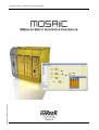
MODULAR SAFETY INTEGRATED CONTROLLER MOSAIC
(Copy of the original instructions)
MODULAR SAFETY INTEGRATED CONTROLLER
1
8540780 • 18th January 2011 • Rev.8
Dichiarazione CE di conformità
EC declaration of conformity
Torino, 15/06/2010
REER SpA
via Carcano 32
10153 – Torino
Italy
dichiara che il controllore integrato MOSAIC costituisce un dispositivo di sicurezza realizzato in conformità alle seguenti
Direttive Europee:
declares that the integrated controller MOSAIC is a safety device complying with the following European Directives:
2006/42/CE
2004/108/CE
2006/95/CE
"Direttiva Macchine"
"Machine Directive"
"Direttiva Compatibilità Elettromagnetica"
"Electromagnetic Compatibility Directive"
"Direttiva Bassa Tensione"
"Low Voltage Directive"
ed è conforme alle seguenti norme:
and complies with the following standards:
CEI EN 61131-2
(07/2007)
ISO 13849-1
(06/2008)
Controllori programmabili - Parte 2: Specifiche e prove delle apparecchiature.
Programmable controllers - Part 2. Equipment requirements and tests.
Sicurezza del macchinario: Parti dei sistemi di comando legate alla sicurezza. Parte 1: Principi generali per la progettazione.
Safety of machinery:- Safety-related parts of control systems - Part 1: General principles for design.
EN 61496-1
(11/2005)
Sicurezza del macchinario: Dispositivi Elettrosensibili di protezione, Parte 1: Requisiti generali e tests.
IEC 61508-1
(04/2010)
Sicurezza funzionale di impianti elettrici/elettronici/programmabili legati alla sicurezza: Requisiti generali.
IEC 61508-2
(04/2010)
IEC 61508-3
(04/2010)
IEC 61784-3
(12/2007)
IEC 62061
(01/2005)
Safety of machinery : Electro sensitive protective equipment, Part 1: General requirements and tests.
Functional safety of electrical/electronic programmable electronic safety related systems: General requirements.
Sicurezza funzionale di impianti elettrici/elettronici/programmabili legati alla sicurezza:
Requisiti per impianti elettrici/elettronici/programmabili legati alla sicurezza.
Functional safety of electrical/electronic/programmable electronic safety related systems:
Requirements for electrical/electronic/programmable electronic safety-related systems.
Sicurezza funzionale di impianti elettrici/elettronici/programmabili legati alla sicurezza: Requisiti Software.
Functional safety of electrical/electronic programmable electronic safety related systems: Software requirements.
Reti di comunicazione industriali - Profili - Parte 3: Sicurezza funzionale dei bus di campo Norme generali e profilo definizioni.
Industrial communication networks - Profiles - Part 3: Functional safety fieldbuses General rules and profile definitions.
Sicurezza del macchinario. Sicurezza funzionale dei sistemi di comando e controllo elettrici, elettronici e programmabili
correlati alla sicurezza.
Safety of machinery - Functional safety of safety-related electrical, electronic and programmable electronic control systems.
raggiungendo il livello di sicurezza pari a: SIL 3 / SILCL 3 / PL e/ Cat. 4 / Tipo 4 (v. standard corrispondenti)
reaching a safety level corresponding to : SIL 3 / SILCL 3 / PL e / Cat. 4 / Type 4 (see related standards)
ed è identico all'esemplare esaminato ed approvato con esame di tipo CE da:
and is identical to the specimen examined and approved with a CE - type approval by:
TÜV SÜD Rail GmbH – Ridlerstrasse 65 – D-80339 – Muenchen – Germany
Carlo Pautasso
Direttore Tecnico
Technical Director
Simone Scaravelli
Amministratore Delegato
Managing director
MODULAR SAFETY INTEGRATED CONTROLLER MOSAIC
MODULAR SAFETY INTEGRATED CONTROLLER
CONTENTS
INTRODUCTION .................................................................................................................................................6
Contents of this handbook ................................................................................ 6
Important safety instructions............................................................................. 6
Abbreviations and symbols................................................................................ 7
Applicable standards ......................................................................................... 7
OVERVIEW.............................................................................................................................................................8
PRODUCT COMPOSITION..............................................................................................................................9
INSTALLATION ................................................................................................................................................ 10
Mechanical fastening ....................................................................................... 10
Calculation of safety distance of an ESPE connected to MOSAIC ....................... 11
Electrical connections ...................................................................................... 11
Instructions concerning connection cables. .................................................. 12
USB input ..................................................................................................... 12
MOSAIC Configuration Memory (MCM).......................................................... 13
MULTIPLE LOAD function........................................................................... 13
RESTORE function...................................................................................... 13
EXAMPLE OF CONNECTION OF MOSAIC TO THE MACHINE CONTROL SYSTEM 17
CHECKLIST AFTER INSTALLATION .................................................................... 17
OPERATING DIAGRAM ................................................................................................................................. 18
SIGNALS .............................................................................................................................................................. 19
INPUTS ............................................................................................................ 19
MASTER ENABLE ........................................................................................... 19
NODE SEL ..................................................................................................... 19
RESTART_FBK ............................................................................................... 20
OUTPUTS ......................................................................................................... 21
OUT STATUS................................................................................................. 21
OUT TEST ..................................................................................................... 21
OSSD (M1, MI8O2) ........................................................................................ 21
OSSD (MO2, MO4) ........................................................................................ 21
SAFETY RELAYS (MR2, MR4) .......................................................................... 22
Characteristics of the output circuit.............................................................. 22
MR2/MR4 internal contacts diagram............................................................. 22
Example of module connection MR2 static OSSD outputs of a module M1 .... 23
Switching operation timing diagram. ............................................................ 23
GENERAL SYSTEM CHARACTERISTICS ............................................................ 24
Safety level parameters ............................................................................. 24
General data.............................................................................................. 24
Enclosure .................................................................................................. 25
M1 module................................................................................................ 25
MI8O2 module .......................................................................................... 25
MI8 - MI16 modules .................................................................................. 26
MO2 - MO4 modules ................................................................................. 26
MR2 - MR4 modules .................................................................................. 26
MECHANICAL DIMENSIONS............................................................................... 27
SIGNALS .......................................................................................................... 28
Master M1 (Figure 9) .................................................................................... 28
8540780 • 18th January 2011 • Rev.8
3
English
TECHNICAL FEATURES ................................................................................................................................ 24
MODULAR SAFETY INTEGRATED CONTROLLER MOSAIC
MI8O2 (Figure 10) ........................................................................................ 29
MI8 (Figure 11)............................................................................................. 30
MI16 (Figure 12)........................................................................................... 31
MO2 (Figure 13) ........................................................................................... 32
MO4 (Figure 14) ........................................................................................... 33
MR2 (Figure 15) / MR4 (Figure 16)................................................................ 34
TROUBLESHOOTING ......................................................................................... 35
Master M1 (Figure 17) .................................................................................. 35
MI8O2 (Figure 18) ........................................................................................ 36
MI8 (Figure 19)............................................................................................. 37
MI16 (Figure 20)........................................................................................... 38
MO2 / MO4 (Figure 21) ................................................................................ 39
MOSAIC SAFETY DESIGNER SOFTWARE .............................................................................................. 40
English
Installing the software ..................................................................................... 40
PC HARDWARE requirements ........................................................................ 40
PC SOFTWARE requirements ......................................................................... 40
How to install MSD ....................................................................................... 40
Fundamentals............................................................................................... 41
Standard tool bar ......................................................................................... 42
Create a new project (configure the MOSAIC system).................................... 43
EDIT CONFIGURATION (composition of the various modules)........................ 44
Change user parameters .............................................................................. 44
OBJECTS - OPERATOR - CONFIGURATION tool bars........................................ 45
Creating the diagram (Figure 16).................................................................. 46
Example of a project .................................................................................... 47
Project validation ...................................................................................... 47
Project report ............................................................................................ 47
Connect to Mosaic..................................................................................... 48
Sending the configuration to the MOSAIC.................................................. 48
Configuration LOG .................................................................................... 48
Upload system configuration..................................................................... 49
Disconnecting System ............................................................................... 49
MONITOR (I/O status in real time - textual) ............................................... 49
MONITOR (I/O status in real time - textual - graphic) ................................. 50
Password protection ..................................................................................... 51
Level 1 password ...................................................................................... 51
Level 2 password ...................................................................................... 51
Password Change ...................................................................................... 51
TESTING the system ..................................................................................... 52
OBJECT FUNCTION BLOCKS .............................................................................. 53
OUTPUT OBJECTS.......................................................................................... 53
OSSD (safety outputs)................................................................................ 53
STATUS (signal output).............................................................................. 53
INPUT OBJECTS ............................................................................................. 54
E-STOP (emergency stop)........................................................................... 54
E-GATE (safety gate device) ....................................................................... 55
ENABLE (enable key) .................................................................................. 56
ESPE (optoelectronic safety light curtain / laser scanner) ........................... 57
FOOTSWITCH (safety pedal)....................................................................... 59
MOD-SEL (safety selector) .......................................................................... 60
PHOTOCELL (safety photocell) ................................................................... 60
TWO-HAND (bimanual control) .................................................................. 61
4
8540780 • 18th January 2011 • Rev.8
MODULAR SAFETY INTEGRATED CONTROLLER MOSAIC
SENSOR ..................................................................................................... 62
S-MAT (safety mat) .................................................................................... 63
SWITCH ..................................................................................................... 64
COMMENTS ............................................................................................... 65
TITLE......................................................................................................... 65
OPERATOR FUNCTION BLOCKS......................................................................... 65
LOGICAL OPERATORS ................................................................................... 65
AND .......................................................................................................... 65
NAND........................................................................................................ 66
NOT .......................................................................................................... 66
OR............................................................................................................. 66
NOR .......................................................................................................... 67
XOR........................................................................................................... 67
XNOR ........................................................................................................ 67
MULTIPLEXER............................................................................................. 68
MEMORY OPERATORS ................................................................................... 68
D FLIP FLOP (max number = 8) .................................................................. 68
SR FLIP FLOP.............................................................................................. 69
USER RESTART MANUAL (max number = 8 with RESTART MONITORED) ..... 69
USER RESTART MONITORED (max number = 8 with RESTART MANUAL) .... 69
COUNTER OPERATORS .................................................................................. 70
COUNTER operator is a pulse counter that sets output Q to 1 (TRUE) as soon
as the desired count is reached. ................................................................ 70
COUNTER (max number = 8). .................................................................... 70
TIMER OPERATORS (max number = 8)........................................................... 70
CLOCKING................................................................................................. 70
MONOSTABLE............................................................................................ 71
PASSING MAKE CONTACT .......................................................................... 72
DELAY ....................................................................................................... 73
MUTING OPERATORS (max number = 4)........................................................ 74
"Concurrent" MUTING ................................................................................ 74
MUTING “L” ............................................................................................... 75
"Sequential" MUTING ................................................................................. 76
MUTING “T” ............................................................................................... 77
SPECIAL APPLICATIONS ................................................................................. 78
Output delay with manual ......................................................................... 78
English
ACCESSORIES AND SPARE PARTS........................................................................................................... 79
WARRANTY ....................................................................................................................................................... 80
8540780 • 18th January 2011 • Rev.8
5
MODULAR SAFETY INTEGRATED CONTROLLER MOSAIC
INTRODUCTION
Contents of this handbook
This handbook describes how to use the MOSAIC programmable safety module and its
expansion units ("SLAVES");
it includes:
• a description of the system
• method of installation
• connections
• signals
• troubleshooting
• use of the configuration SW
Important safety instructions
This
safety alert symbol indicates a potential personal safety hazard. Failure to
comply with instructions bearing this symbol could pose a very serious risk to
personnel.
Î
This symbol indicates an important instruction.
The MOSAIC is built to the following safety levels: SIL 3, SILCL 3, PL e, Cat. 4, Type 4
English
in accordance with the applicable standards.
However, the definitive SIL and PL of the application will depend on the number of
safety components, their parameters and the connections that are made, as per the
risk analysis.
Read the "Applicable Standards" section carefully.
Perform an in-depth risk analysis to determine the appropriate safety level for your
specific application, on the basis of all the applicable standards.
Always test the complete system whenever new safety components are added (see
the "TESTING the system" section).
The ambient temperature in the place where the system is installed must be
compatible with the operating temperature parameters stated on the product label
and in the specifications.
For all matters concerning safety, if necessary, contact your country's competent
safety authorities or the competent trade association.
6
8540780 • 18th January 2011 • Rev.8
MODULAR SAFETY INTEGRATED CONTROLLER MOSAIC
Abbreviations and symbols
MCM =
MSC =
MSD =
OSSD =
MTTFd =
PL =
PFHd =
SIL =
SILCL =
SW =
MOSAIC Configuration Memory: memory chip for MOSAIC M1 (accessory)
MOSAIC Safety Communication: proprietary bus for expansion units
MOSAIC Safety Designer: MOSAIC configuration SW running in Windows
Output Signal Switching Device: solid state safety output
Mean Time to Dangerous Failure
Performance Level
Probability of a dangerous failure per Hour
Safety Integrity Level
Safety Integrity Level Claim Limit
Software
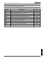
Applicable standards
MOSAIC complies with the following European Directives:
• 2006/42/EC
"Machinery Directive"
• 2004/108/EC
"Electromagnetic Compatibility Directive"
• 2006/95/EC
"Low Voltage Directive"
and is built to the following standards:
CEI EN 61131-2
ISO 13489-1
EN 61496-1
IEC 61508-1
IEC 61508-2
IEC 61508-3
IEC 61784-3
IEC 62061
Programmable controllers, part 2:
Equipment requirements and tests
Safety of machinery:
Safety related parts of control systems. General principles for design
Safety of machinery: Electro-sensitive protective equipment. Part 1: General
requirements and tests.
Functional safety of electrical/electronic/programmable electronic safetyrelated systems: General requirements.
Functional safety of electrical/electronic/programmable electronic safetyrelated systems: Requirements for electrical/electronic/programmable
electronic safety-related systems.
Functional safety of electrical/electronic/programmable electronic safetyrelated systems: Software requirements.
Digital data communication for measurement and control: Functional safety
fieldbuses.
Safety of machinery. Functional safety of safety-related electrical, electronic
and programmable electronic control systems
English
Table 1
8540780 • 18th January 2011 • Rev.8
7
MODULAR SAFETY INTEGRATED CONTROLLER MOSAIC
OVERVIEW
MOSAIC is a modular safety controller. It consists of a master unit (M1), which can
be configured using the MSD graphic interface, and a number of expansion units
connected to the M1 via the proprietary MSC bus.
The M1 can also be used as a stand-alone device. It has 8 safety inputs and 2
independent programmable dual channel outputs.
Î
The following expansions are available: I/O expansions (MI8O2), input only
expansions (MI8 and MI16), output only expansions (MO2 and MO4), guided
contact safety relay output modules (MR2 and MR4) and diagnostic connections to
the main fieldbuses:
MBP (PROFIBUS), MBC (CanOpen), MBD (DeviceNet).
MOSAIC is capable of monitoring the following safety sensors and commands:
optoelectronic sensors (safety light curtains, scanners, safety photocells),
mechanical switches, safety mats, emergency stops, two-hand controls, all
managed by a single flexible and expandable device.
The system must consist of just one Master M1 and a number of electronic
expansions that can range from 0 to a maximum of 7, not more than 4 of which
of the same type. There is no limit to the number of relay modules that can be
installed.
With 7 expansions, the system can have up to 72 inputs and 8 dual channel safety
outputs. The MASTER and its SLAVE units communicate via the 5-way MSC bus
(ReeR proprietary bus), physically arranged on the rear panel of each unit.
The MSD software is capable of creating complex logics, using logical operators
and safety functions such as muting, timer, counters, etc.
All this is performed through an easy and intuitive graphic interface.
The configuration performed on the PC is sent to the M1 via USB connection; the
file resides in the M1 and can also be saved on the proprietary MCM memory chip
(accessory). The configuration can therefore quickly be copied to another M1 unit.
The MOSAIC system is certified to the maximum safety level envisaged by the
applicable industrial safety standards (SIL 3, SILCL 3, PL e, Cat. 4).
English
Î
8
8540780 • 18th January 2011 • Rev.8
MODULAR SAFETY INTEGRATED CONTROLLER MOSAIC
PRODUCT COMPOSITION
The MOSAIC M1is supplied with:
• CD-ROM containing the free MSD SW, this PDF multi-language handbook and
other product literature.
• Multi-language installation sheet.
Î
NB: the rear panel MSC connector and MCM memory can be ordered separately as
accessories.
The expansion units are supplied with:
• Multilingual Installation sheet.
• Rear panel MSC connector (not present in the MR2 and MR4 which are
connected via terminal blocks only).
NB: to install an expansion unit (excluding relays) you will need the MSC connector
supplied with the unit plus another MSC for the connection to the M1. This can be
ordered separately as an accessory.
English
Î
8540780 • 18th January 2011 • Rev.8
9
MODULAR SAFETY INTEGRATED CONTROLLER MOSAIC
INSTALLATION
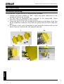
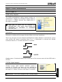
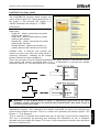
Mechanical fastening
Fix the MOSAIC system units to a 35mm DIN rail as follows:
1. Connect the same number of "MSC" 5-pole rear panel connectors as the
number of units to be installed.
2. Fix the train of connectors thus obtained to the Omega DIN 35mm
(EN 5022) rail (hooking them at the top first).
3. Fasten the units to the rail, arranging the contacts on the base of the unit
on the respective connector. Press the unit gently until you feel it snap into
place.
4. To remove a unit, use a screwdriver to pull down the locking latch on the
back of the unit; then lift the unit upwards and pull.
1
2b
2a
3
4
English
Figure 1
10
8540780 • 18th January 2011 • Rev.8
MODULAR SAFETY INTEGRATED CONTROLLER MOSAIC
Calculation of safety distance of an ESPE connected to MOSAIC
Any Electro-sensitive Protective Equipment device connected to MOSAIC, must be
positioned at a distance equal to or greater than the minimum safety distance S so that
the dangerous point can be reached only after stopping the dangerous movement of the
machine.
The european standard:
- ISO 13855:2010- (EN 999:2008) Safety of machinery - Positioning of safeguards with
respect to the approach speeds of parts of the human body.1
provides the elements to calculate the proper safety distance.
Carefully read the installation manual of each device for specific information on the
correct positioning.
Remember that the total response time depends on:
MOSAIC response time + ESPE response time + response time of the machine (i.e. the
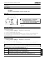
time taken by the machine to stop the dangerous movement from the moment in
which the stop signal is transmitted).
Electrical connections
The MOSAIC system units are provided with terminal
blocks for the electrical connections. Each unit can
have 8, 16 or 24 terminals.
Each unit also has a rear panel plug-in connector (for
communication with the master and with the other
expansion units).
The MR2 and MR4 are connected via terminal blocks
only.
Install safety units in an enclosure with a protection class of at least IP54.
The supply voltage to the units must be 24Vdc ±20% (PELV, in compliance with the
standard EN 60204-1 (Chapter 6.4)).
Do not use the MOSAIC to supply external devices.
The same ground connection (0VDC) must be used for all system components.
1
"Describe the methods that designers can use to calculate the minimum safety distance from a specific dangerous point
for the safety devices, particularly Electro-sensitive devices (eg. light curtains), safety-mats or pressure sensitive floors and
bimanual control. It contains a rule to determine the placement of safety devices based on approach speed and the
stopping time of the machine, which can reasonably be extrapolated so that it also includes the interlocking guards without
guard locking."
8540780 • 18th January 2011 • Rev.8
11
English
MODULAR SAFETY INTEGRATED CONTROLLER MOSAIC
Instructions concerning connection cables.
Î
Cables used for connections must be AWG26 ÷ AWG14. Cables used for connections
of longer than 50m must have a cross-section of at least 1mm2 (AWG16).
Î
We recommend the use of separate power supplies for the safety module and for
other electrical power equipment (electric motors, inverters, frequency converters)
or other sources of disturbance.
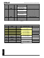
Connections of each single MOSAIC system unit are listed in the table below:
TERMINAL
SIGNAL
TYPE
Master M1
DESCRIPTION
1
24VDC
-
24VDC power supply
2
MASTER_ENABLE1
Input
Master Enable 1
3
MASTER_ENABLE2
Input
Master Enable 2
4
5
6
7
8
9
10
11
12
13
14
15
16
17
18
19
20
21
22
23
24
GND
OSSD1_A
OSSD1_B
RESTART_FBK1
OUT_STATUS1
OSSD2_A
OSSD2_B
RESTART_FBK2
OUT_STATUS2
OUT_TEST1
OUT_TEST2
OUT_TEST3
OUT_TEST4
INPUT1
INPUT2
INPUT3
INPUT4
INPUT5
INPUT6
INPUT7
INPUT8
Output
Output
Input
Output
Output
Output
Input
Output
Output
Output
Output
Output
Input
Input
Input
Input
Input
Input
Input
Input
0VDC power supply
Static output 1
Feedback/Restart 1
Programmable digital output
Static output 2
Feedback/Restart 2
Programmable digital output
Short circuit detected output
Short circuit detected output
Short circuit detected output
Short circuit detected output
Digital input 1
Digital input 2
Digital input 3
Digital input 4
Digital input 5
Digital input 6
Digital input 7
Digital input 8
OPERATION
Input ("type B" according to
EN 61131-2 )
Input ("type B" according to
EN 61131-2 )
PNP active high
PNP active high
Input according to EN 61131-2
PNP active high
PNP active high
PNP active high
Input according to EN 61131-2
PNP active high
PNP active high
PNP active high
PNP active high
PNP active high
Input according to EN 61131-2
Input according to EN 61131-2
Input according to EN 61131-2
Input according to EN 61131-2
Input according to EN 61131-2
Input according to EN 61131-2
Input according to EN 61131-2
Input according to EN 61131-2
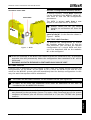
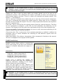
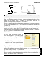
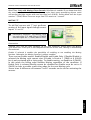
USB input
English
The MOSAIC master M1 includes a
USB 2.0 connector for connection to
a
Personal
Computer
where
the MSD (MOSAIC Safety Designer)
configuration SW resides.
A USB cable of the correct size is
available as an accessory (CSU).
Figure 2 - USB 2.0 front panel connector
12
8540780 • 18th January 2011 • Rev.8
MODULAR SAFETY INTEGRATED CONTROLLER MOSAIC
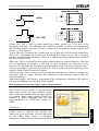
TECHNICAL DATA LABEL
MCM LABEL
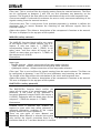
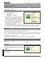
MOSAIC Configuration Memory (MCM)
A backup memory, called MCM (optional)
can be installed in the MOSAIC master M1
and used to save the SW configuration
parameters.
The MCM is written each time a new
project is sent from the PC to the M1.
Î
Always switch the M1 off before
logging on to/logging off from the
MCM.
Insert the card in the slot in the rear
panel of the M1 (in the direction shown in
Figure 3 - MCM).
MULTIPLE LOAD function
Figure 3 - MCM
To perform the configuration of several
M1 modules without using a PC and the
USB connector, you can save the desired
configuration on a single MCM and then
use it to download data on the modules
M1 to be configured.
If the file contained in the MCM is not identical to the one contained in M1, an overwrite
operation that will permanently delete the configuration data contained in M1 will be
performed.
WARNING: ALL DATA PREVIOUSLY CONTAINED IN M1 WILL BE LOST.
RESTORE function
If the M1 unit is damaged, you can replace it with a new one; having already saved all the
configurations on the MCM, all you need to do is insert the MCM in the new M1 and
switch on the MOSAIC system, that will immediately load the backup configuration. In this
way, the work interruptions will be minimized.
Î
The LOAD and RESTORE functions can be disabled via SW. (see Figure 26)
Î
In order to be used, the expansion units must be addressed at the time of
installation (see the NODE SEL section).
Each time MCM is used, carefully check that the chosen configuration is the one that
English
was planned for that particular system. Try again a fully functional test of the system
composed of Mosaic plus all devices connected to it (see the TESTING the system
section).
8540780 • 18th January 2011 • Rev.8
13
MODULAR SAFETY INTEGRATED CONTROLLER MOSAIC
MI8O2
TERMINAL
SIGNAL
TYPE
1
24VDC
2
NODE_SEL0
Input
3
NODE_SEL1
Input
4
GND
5
OSSD1_A
Output
6
OSSD1_B
Output
7
RESTART_FBK1 Input
8
OUT_STATUS1 Output
9
OSSD2_A
Output
10
OSSD2_B
Output
11
RESTART_FBK2 Input
12
OUT_STATUS2 Output
13
OUT_TEST1
Output
14
OUT_TEST2
Output
15
OUT_TEST3
Output
16
OUT_TEST4
Output
17
INPUT1
Input
18
INPUT2
Input
19
INPUT3
Input
20
INPUT4
Input
21
INPUT5
Input
22
INPUT6
Input
23
INPUT7
Input
24
INPUT8
Input
DESCRIPTION
24VDC power supply
Node selection
0VDC power supply
Static output 1
Feedback/Restart 1
Programmable digital output
Static output 2
Feedback/Restart 2
Programmable digital output
Short circuit detected output
Short circuit detected output
Short circuit detected output
Short circuit detected output
Digital input 1
Digital input 2
Digital input 3
Digital input 4
Digital input 5
Digital input 6
Digital input 7
Digital input 8
OPERATION
Input ("type B" according to EN 61131-2 )
Input ("type B" according to EN 61131-2 )
PNP active high
PNP active high
Input according to EN 61131-2
PNP active high
PNP active high
PNP active high
Input according to EN 61131-2
PNP active high
PNP active high
PNP active high
PNP active high
PNP active high
Input according to EN 61131-2
Input according to EN 61131-2
Input according to EN 61131-2
Input according to EN 61131-2
Input according to EN 61131-2
Input according to EN 61131-2
Input according to EN 61131-2
Input according to EN 61131-2
Table 2
MI16
English
TERMINAL
1
2
3
4
5
6
7
8
9
10
11
12
13
14
15
16
17
18
19
20
21
22
23
24
SIGNAL
24VDC
NODE_SEL0
NODE_SEL1
GND
INPUT1
INPUT2
INPUT3
INPUT4
OUT_TEST1
OUT_TEST2
OUT_TEST3
OUT_TEST4
INPUT5
INPUT6
INPUT7
INPUT8
INPUT9
INPUT10
INPUT11
INPUT12
INPUT13
INPUT14
INPUT15
INPUT16
TYPE
Input
Input
Input
Input
Input
Input
Output
Output
Output
Output
Input
Input
Input
Input
Input
Input
Input
Input
Input
Input
Input
Input
DESCRIPTION
24VDC power supply
Node selection
0VDC power supply
Digital input 1
Digital input 2
Digital input 3
Digital input 4
Short circuit detected output
Short circuit detected output
Short circuit detected output
Short circuit detected output
Digital input 5
Digital input 6
Digital input 7
Digital input 8
Digital input 9
Digital input 10
Digital input 11
Digital input 12
Digital input 13
Digital input 14
Digital input 15
Digital input 16
OPERATION
Input ("type B" according to EN 61131-2 )
Input ("type B" according to EN 61131-2 )
Input according to EN 61131-2
Input according to EN 61131-2
Input according to EN 61131-2
Input according to EN 61131-2
PNP active high
PNP active high
PNP active high
PNP active high
Input according to EN 61131-2
Input according to EN 61131-2
Input according to EN 61131-2
Input according to EN 61131-2
Input according to EN 61131-2
Input according to EN 61131-2
Input according to EN 61131-2
Input according to EN 61131-2
Input according to EN 61131-2
Input according to EN 61131-2
Input according to EN 61131-2
Input according to EN 61131-2
Table 3
14
8540780 • 18th January 2011 • Rev.8
MODULAR SAFETY INTEGRATED CONTROLLER MOSAIC
MI8
TERMINAL
1
2
3
4
5
6
7
8
9
10
11
12
13
14
15
16
SIGNAL
24VDC
NODE_SEL0
NODE_SEL1
GND
INPUT1
INPUT2
INPUT3
INPUT4
OUT_TEST1
OUT_TEST2
OUT_TEST3
OUT_TEST4
INPUT5
INPUT6
INPUT7
INPUT8
TYPE
Input
Input
Input
Input
Input
Input
Output
Output
Output
Output
Input
Input
Input
Input
DESCRIPTION
24VDC power supply
Node selection
0VDC power supply
Digital input 1
Digital input 2
Digital input 3
Digital input 4
Short circuit detected output
Short circuit detected output
Short circuit detected output
Short circuit detected output
Digital input 5
Digital input 6
Digital input 7
Digital input 8
OPERATION
Input ("type B" according to EN 61131-2 )
Input ("type B" according to EN 61131-2 )
Input according to EN 61131-2
Input according to EN 61131-2
Input according to EN 61131-2
Input according to EN 61131-2
PNP active high
PNP active high
PNP active high
PNP active high
Input according to EN 61131-2
Input according to EN 61131-2
Input according to EN 61131-2
Input according to EN 61131-2
Table 4
MO4
TERMINAL
1
2
3
4
5
6
7
8
9
10
11
12
13
14
15
16
17
18
19
20
21
22
23
24
SIGNAL
24VDC
NODE_SEL0
NODE_SEL1
GND
OSSD1_A
OSSD1_B
RESTART_FBK1
OUT_STATUS1
OSSD2_A
OSSD2_B
RESTART_FBK2
OUT_STATUS2
24VDC
24VDC
GND
GND
OSSD4_A
OSSD4_B
RESTART_FBK4
OUT_STATUS4
OSSD3_A
OSSD3_B
RESTART_FBK3
OUT_STATUS3
TYPE
Input
Input
Output
Output
Input
Output
Output
Output
Input
Output
Output
Output
Input
Output
Output
Output
Input
Output
DESCRIPTION
24VDC power supply
Node selection
0VDC power supply
Static output 1
Feedback/Restart 1
Programmable digital output
Static output 2
Feedback/Restart 2
Programmable digital output
24VDC power supply
24VDC power supply
0VDC power supply
0VDC power supply
Static output 4
Feedback/Restart 4
Programmable digital output
Static output 3
Feedback/Restart 3
Programmable digital output
OPERATION
Input ("type B" according to EN 61131-2 )
Input ("type B" according to EN 61131-2 )
PNP active high
PNP active high
Input according to EN 61131-2
PNP active high
PNP active high
PNP active high
Input according to EN 61131-2
PNP active high
OSSD1/2 power supply
OSSD3/4 power supply
PNP active high
PNP active high
Input according to EN 61131-2
PNP active high
PNP active high
PNP active high
Input according to EN 61131-2
PNP active high
English
Table 5
8540780 • 18th January 2011 • Rev.8
15
MODULAR SAFETY INTEGRATED CONTROLLER MOSAIC
MO2
TERMINAL
SIGNAL
TYPE
1
24VDC
2
NODE_SEL0
Input
3
NODE_SEL1
Input
4
GND
5
OSSD1_A
Output
6
OSSD1_B
Output
7
RESTART_FBK1 Input
8
OUT_STATUS1 Output
9
OSSD2_A
Output
10
OSSD2_B
Output
11
RESTART_FBK2 Input
12
OUT_STATUS2 Output
13
24VDC
14
n.c.
15
GND
16
n.c.
-
DESCRIPTION
24VDC power supply
Node selection
0VDC power supply
Static output 1
Feedback/Restart 1
Condition of outputs 1A/1B
Static output 2
Feedback/Restart 2
Condition of outputs 2A/2B
24VDC power supply
0VDC power supply
-
OPERATION
Input ("type B" according to EN 61131-2 )
Input ("type B" according to EN 61131-2 )
PNP active high
PNP active high
Input according to EN 61131-2
PNP active high
PNP active high
PNP active high
Input according to EN 61131-2
PNP active high
OSSD1/2 power supply
-
Table 6
MR4
TERMINAL
1
4
5
6
7
9
10
13
14
15
16
11
12
17
18
19
21
22
23
24
SIGNAL
24VDC
GND
OSSD1_A
OSSD1_B
FBK_K1_K2_1
A_NC1
B_NC1
A_NO11
B_NO11
A_NO12
B_NO12
A_NC2
B_NC2
OSSD2_A
OSSD2_B
FBK_K1_K2_2
A_NO21
B_NO21
A_NO22
B_NO22
TYPE
Input
Input
Output
Output
Output
Output
Output
Output
Output
Output
Output
Input
Input
Output
Output
Output
Output
Output
DESCRIPTION
24VDC power supply
0VDC power supply
OPERATION
-
Control ZONE 1
PNP active high
Feedback K1K2 ZONE 1
NC contact ZONE 1
NO1 contact ZONE 1
NO2 contact ZONE 1
NC contact ZONE 2
Control ZONE 2
PNP active high
Feedback K1K2 ZONE 2
NO1 contact ZONE 2
NO2 contact ZONE 2
English
Table 7
16
8540780 • 18th January 2011 • Rev.8
MODULAR SAFETY INTEGRATED CONTROLLER MOSAIC
MR2
TERMINAL
1
SIGNAL
24VDC
TYPE
-
DESCRIPTION
24VDC power supply
OPERATION
-
4
GND
-
0VDC power supply
-
5
OSSD1_A
Input
6
OSSD1_B
Input
Control ZONE 1
PNP active high
7
FBK_K1_K2_1
Output
9
A_NC1
Output
10
B_NC1
Output
13
A_NO11
Output
14
B_NO11
Output
15
A_NO12
Output
16
B_NO12
Output
Feedback K1K2 ZONE 1
NC contact ZONE 1
NO1 contact ZONE 1
NO2 contact ZONE 1
Table 8
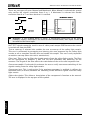
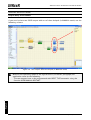
EXAMPLE OF CONNECTION OF MOSAIC TO THE MACHINE CONTROL SYSTEM
Figure 4
CHECKLIST AFTER INSTALLATION
The MOSAIC system is able to detect the faults that occurs in each own module.
Anyway to have the system perfect operation perform the following checks at start up
and at least every one year:
Î
Operate a complete system TEST (see "TESTING the system")
Verify that all the cables are correctly inserted and the terminal blocks well screwed.
Verify that all the leds (indicators) light on correctly.
Verify the positioning of all the sensors connected to MOSAIC.
Verify the correct fixing of MOSAIC to the Omega rail.
Verify that all the external indicators (lamps) work properly.
After installation, maintenance and after any eventual configuration change perform
a System TEST as described in the paragraph "TESTING the system" at page 52.
8540780 • 18th January 2011 • Rev.8
17
English
1.
2.
3.
4.
5.
6.
MODULAR SAFETY INTEGRATED CONTROLLER MOSAIC
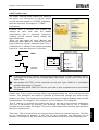
OPERATING DIAGRAM
Mechanical fastening
Electrical connections
between the Mosaic
modules and with the
external sensors
Designing the diagram
NO
Validation
sw OK ?
YES
Connection
via USB with PSW
Downloading the
diagram to M1
NO
Configuration
control on M1
OK?
YES
End of connection
via USB
English
System
startup
18
8540780 • 18th January 2011 • Rev.8
MODULAR SAFETY INTEGRATED CONTROLLER MOSAIC
SIGNALS
INPUTS
MASTER ENABLE
The MOSAIC M1 master has two inputs: MASTER_ENABLE1 and MASTER_ENABLE2.
Î
These signals must both be permanently set to logic level 1 (24VDC) for the MOSAIC
to operate. If the user needs to disable the MOSAIC simply lower these inputs to
logic level 0 (0VDC).
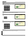
NODE SEL
The NODE_SEL0 and NODE_SEL1 inputs (on the SLAVE units) are used to attribute a
physical address to the slave units with the connections shown in Table 9:
NODE_SEL1
NODE_SEL0
SLAVE 0
0 (or not connected)
0 (or not connected)
SLAVE 1
0 (or not connected)
24VDC
SLAVE 2
24VDC
0 (or not connected)
SLAVE 3
24VDC
24VDC
Table 9
It is not allowed to use the same physical address on two units of the same type.
English
Î
8540780 • 18th January 2011 • Rev.8
19
MODULAR SAFETY INTEGRATED CONTROLLER MOSAIC
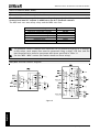
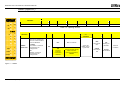
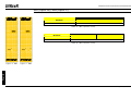
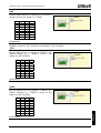
RESTART_FBK
The RESTART_FBK signal input allows the MOSAIC to verify an EDM (External Device
Monitoring) feedback signal from the external contactors, and to monitor
Manual/Automatic operation (See the list of possible connections in Table 10).
Each OSSD pairs has a RESTART_FBK corresponding input.
The RESTART command must be installed outside the danger area in a position where
the danger area and the entire work area concerned are clearly visible.
It must not be possible to reach the control from inside the danger area.
MODE OF
OPERATION
EDM
With K1_K2
control
RESTART_FBK
24V
K1
K2
ext_Restart_fbk
AUTOMATIC
Without
K1_K2
control
With K1_K2
control
24V
24V
ext_Restart_fbk
K1
K2
ext_Restart_fbk
MANUAL
Without
K1_K2
control
24V
ext_Restart_fbk
English
Table 10
20
8540780 • 18th January 2011 • Rev.8
MODULAR SAFETY INTEGRATED CONTROLLER MOSAIC
OUTPUTS
OUT STATUS
The OUT
•
•
•
STATUS signal is a programmable digital output that can indicate the status of:
An input.
An output.
A node of the logic diagram designed using the MSD.
OUT TEST
The OUT TEST signals must be used to monitor the presence of short-circuits or
overloads on the inputs (Figure 5).
Î
The maximum number of controllable
inputs for each output OUT TEST is:
- 2 INPUT (parallel connection) (M1, MI802)
- 4 INPUT (parallel connection) (MI16)
Figure 5
OSSD (M1, MI8O2)
The OSSD (static semiconductor safety outputs) are short circuit protected, cross circuit
monitored and supply:
• In the ON condition: Uv-0,75V ÷ Uv (where Uv is 24V ± 20%)
• In the OFF condition: 0V ÷ 2V r.m.s.
The maximum load of 400mA@24V corresponds to a minimum resistive load of 60Ω.
The maximum capacitive load is 0.82µF. The maximum inductive load is 30mH.
OSSD (MO2, MO4)
The OSSD (static semiconductor safety outputs) are short circuit protected, cross circuit
monitored and supply:
• In the ON condition: Uv-0,75V ÷ Uv (where Uv is 24V ± 20%)
• In the OFF condition: 0V ÷ 2V r.m.s.
The maximum load of 400mA@24V corresponds to a minimum resistive load of 60Ω.
The maximum capacitive load is 0.82µF. The maximum inductive load is 30mH.
Î
It is not allowed the connection of external devices to the outputs, except as
expected in the configuration performed with the MSD software.
Automatic
The output is activated according to le configurations set by the MSD SW only if the
corresponding RESTART_FBK input is conected to 24VDC.
Manual
The output is activated according to le configurations set by the MSD SW only if corresponding
RESTART_FBK input FOLLOWS A LOGIC TRANSITION OF 0-->1.
Monitored
The output is activated according to le configurations set by the MSD SW only if the
corresponding RESTART_FBK input FOLLOWS A LOGIC TRANSITION OF 0-->1-->0.
Table 11
8540780 • 18th January 2011 • Rev.8
21
English
Each OSSD output can be configured as shown in Table 11:
MODULAR SAFETY INTEGRATED CONTROLLER MOSAIC
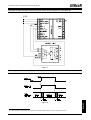
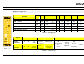
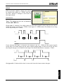
SAFETY RELAYS (MR2, MR4)
Characteristics of the output circuit.
The MR2/MR4 units use guided contact safety relays, each of which provides two N.O.
contacts and one N.C contact in addition to the N.C. feedback contact.
The MR2 unit uses two safety relays and the MR4 uses four.
Excitation voltage
Minimum switchable voltage
Minimum switchable current
Maximum switchable voltage (DC)
Maximum switchable voltage (AC)
Maximum switchable current
Response time
Mechanical life of contacts
Table 12
17...31 VDC
10 VDC
20 mA
250VDC
400VAC
6A
12ms
> 20 x 106
Î
To guarantee correct isolation and avoid the risk of premature ageing of or damage
to the relays, each output line must be protected using a delay 3.5A fuse and the
load characteristics must be consistent with those specified in Table 12.
Î
See the "MR2 - MR4" section (for further details on these relays).
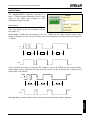
MR2/MR4 internal contacts diagram
English
Figure 6
22
8540780 • 18th January 2011 • Rev.8
MODULAR SAFETY INTEGRATED CONTROLLER MOSAIC
Example of MR2 module connection with static OSSD outputs of a module M12
Figure 7
Switching operation timing diagram.
2
English
Figure 8
If a relay module is connected, the response time of the OSSD linked, must be increased of 12ms.
8540780 • 18th January 2011 • Rev.8
23
MODULAR SAFETY INTEGRATED CONTROLLER MOSAIC
TECHNICAL FEATURES
GENERAL SYSTEM CHARACTERISTICS
Safety level parameters
Parameter
Value
PFHd
10 ÷ 10
SIL
3
SILCL
3
IEC 62061:2005
Type
4
EN 61496-1
PL
e
DCavg
High
MTTFd (years)
30 ÷ 100
Category
4
Device lifetime
20 years
-8
Standard
-7
IEC 61508:1998
ISO 13849-1:2006
IEC 62061:2005
General data
Max number of inputs
72
Max number of outputs
Max number of slave units
(excluding MR2-MR4)
Max number of slave units of the
same type (excluding MR2-MR4)
8
7
4
24VDC ± 20%
Rated voltage
Digital INPUTS
OSSD (M1, MI8O2, MO2, MO4)
Digital OUTPUTS
PNP active high (EN 61131-2)
PNP active high - 400mA@24VDC max
PNP active high - 100mA@24VDC max
Master
10 ms + TInput_filter
19.5 ms
+ TInput_filter
M1 + 2 Slaves
22 ms
+ TInput_filter
M1 + 3 Slaves
24 ms
+ TInput_filter
M1 + 4 Slaves
26 ms
+ TInput_filter
M1 + 5 Slaves
28 ms
+ TInput_filter
M1 + 6 Slaves
30.5 ms
+ TInput_filter
M1 + 7 Slaves
32.5 ms
+ TInput_filter
M1 + 1 Slave
Response time
M1> module connection
Connection cable cross-section
Max length of connections
ReeR proprietary 5-pole bus (MSC)
0.5 ÷ 2.5 mm2
100m
Operating temperature
-10 ÷ 55°C
Storage temperature
-20 ÷ 70°C
Relative humidity
10% ÷ 95%
TInput_filter = max filtering time from among those set on project inputs (see
"INPUTS" section").
English
Î
24
8540780 • 18th January 2011 • Rev.8
MODULAR SAFETY INTEGRATED CONTROLLER MOSAIC
Enclosure
Description
Enclosure material
Electronic housing max 24 pole,
with locking latch mounting
Polyamide
Enclosure protection class
IP 20
Terminal blocks protection class
IP 2X
Fastening
Dimensions (h x l x d)
Quick coupling to rail according to EN 60715
108 x 22.5 x 114.5
M1 module
Rated voltage
Dissipated power
Unit enable (No./description)
Digital INPUTS (No./description)
24VDC ± 20%
3W max
2 / PNP active high "type B" according to EN 61131-2
8 / PNP active high according to EN 61131-2
INPUT FBK/RESTART (No./description)
2 / EDM control / possible Automatic
or Manual operation with RESTART button
Test OUTPUT (No./description)
4 / to check for short-circuits - overloads
Digital OUTPUTS (No./description)
OSSD (No./description)
SLOT for MCM card
Connection to PC
Connection to slave units
2 / programmable - PNP active high
2 pairs / solid state safety outputs PNP active high
400mA@24VDC max
Available
USB 2.0 (Hi Speed) - Max cable length: 3m
via MSC 5-way ReeR proprietary bus
MI8O2 module
Rated voltage
Dissipated power
24VDC ± 20%
3W max
Digital INPUTS (No./description)
8 / PNP active high according to EN 61131-2
Test OUTPUT (No./description)
8 / to check for short-circuits - overloads
Digital OUTPUTS (No./description)
OSSD (No./description)
2 pairs / solid state safety outputs:
PNP active high – 400mA@24VDC max
via MSC 5-way ReeR proprietary bus
English
Connection to M1
2 / programmable - PNP active high
8540780 • 18th January 2011 • Rev.8
25
MODULAR SAFETY INTEGRATED CONTROLLER MOSAIC
MI8 - MI16 modules
Model
MI8
MI16
24VDC ± 20%
Rated voltage
Dissipated power
Digital INPUTS (No./description)
Test OUTPUT (No./description)
Connection to M1
3W max
8
16
PNP active high according to EN 61131-2
4 / to check for short-circuits - overloads
via MSC 5-way ReeR proprietary bus
MO2 - MO4 modules
Model
MO2
MO4
24VDC ± 20%
Rated voltage
Dissipated power
Digital OUTPUTS (No./description)
OSSD (No./description)
Connection to M1
3W max
2
4
programmable - PNP active high
2
4
Solid state safety outputs: PNP active high 400mA@24VDC max
via MSC 5-way ReeR proprietary bus
MR2 - MR4 modules
Model
MR2
MR4
24VDC ± 20%
Rated voltage
Dissipated power
3W max
Switching voltage
240 VAC
Switching current
6A max
N.O. contacts
FEEDBACK contacts
Response time
Mechanical life of contacts
B10d
AC15 230V
DC13 24V
4 N.A. + 2 N.C.
1
2
12ms
> 20 x 106
I = 3A:
I = 1A:
I <= 2A:
300.000
750.000
10.000.000
Via front-panel terminal strip
(no connection via MSC bus)
English
Connection to output module
2 N.A. + 1 N.C.
26
8540780 • 18th January 2011 • Rev.8
MODULAR SAFETY INTEGRATED CONTROLLER MOSAIC
MECHANICAL DIMENSIONS
22.5 mm
114.5 mm
99 mm
108 mm
English
Figure 9
8540780 • 18th January 2011 • Rev.8
27
MODULAR SAFETY INTEGRATED CONTROLLER MOSAIC
SIGNALS
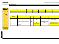
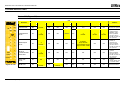
Master M1 (Figure 10)
LED
RUN
IN FAIL
EXT FAIL
COM
ENA
GREEN
RED
RED
ORANGE
BLUE
ON
ON
ON
ON
ON
ON
MEANING
RUN
IN
EXT
COM
ENA
FAIL
IN
OSSD
CLEAR
STATUS
Power on - initial TEST
OSDD1/2
CLEAR1/2
STATUS1/2
YELLOW
YELLOW
Red
ON
ON
OFF
Red
OFF
OFF
MCM recognised
OFF
OFF
OFF
ON
(max 1s)
ON
(max
1s)
Loading diagram
from MCM card
OFF
OFF
OFF
5
flashes
5
flashes
OFF
Red
OFF
OFF
1
2
MSD requesting connection:
internal configuration not valid or not present
OFF
OFF
OFF
Flashes
slowly
OFF
OFF
Red
OFF
OFF
3
4
MSD requesting connection:
MCM configuration not valid
OFF
OFF
OFF
Flashes
quickly
OFF
OFF
Red
OFF
OFF
5
6
MSD connected M1 stopped
OFF
OFF
OFF
ON
OFF
OFF
Red
OFF
OFF
7
8
1
2
1
2
1
2
Table 13 - Opening Screen
LED
MEANING
NORMAL
OPERATION
EXTERNAL FAULT
DETECTED
Figure 10 - M1
RUN
IN FAIL
EXT FAIL
COM
IN1÷8
ENA
OSSD1/2
CLEAR1/2
STATUS1/2
GREEN
RED
RED
ORANGE
YELLOW
BLUE
RED/GREEN
YELLOW
YELLOW
ON
OFF
OFF
op. OK
ON = M1
connected to
PC
OFF=otherwise
INPUT condition
RED with
output OFF
ON = M1
connected to
PC
OFF=otherwise
only the number
of the INPUT with
the incorrect
connection
flashes
ON
waiting for
RESTART
OFF
ON
incorrect
external
connection
detected
ON
MASTER_ENABLE1
and MASTER_ENABLE2
active
OFF
otherwise
ON
GREEN with
output ON
OUTPUT
condition
Flashing
NO feedback
Table 14 - Dynamic Screen
28
8540780 • 18th January 2011 • Rev.8
English
ON
IN1÷8
YELLOW RED/GREEN
MODULAR SAFETY INTEGRATED CONTROLLER MOSAIC
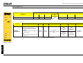
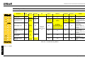
MI8O2 (Figure 11)
LED
FAIL
SEL
IN
OSSD
CLEAR
STATUS
ON
RUN
IN
EXT
0
1
1
2
3
4
5
6
7
8
1
2
1
2
1
2
MEANING
RUN
IN FAIL
EXT FAIL
SEL
IN1÷8
OSSD1/2
CLEAR1/2
STATUS1/2
GREEN
RED
RED
ORANGE
YELLOW
RED/GREEN
YELLOW
YELLOW
ON
ON
ON
ON
ON
Red
ON
ON
Power on - initial TEST
Table 15 - Opening Screen
LED
MEANING
RUN
IN FAIL
EXT FAIL
IN1÷8
SEL
OSSD1/2
CLEAR1/2
STATUS1/2
GREEN
RED
RED
YELLOW
ORANGE
RED/GREEN
YELLOW
YELLOW
OFF
INPUT condition
OFF
if the unit is waiting for
the first communication
from the MASTER
NORMAL
OPERATION
FLASHES
if no INPUT or OUTPUT
requested by the
configuration
ON
if INPUT or OUTPUT
requested by the
configuration
Shows the
NODE_SEL0/1
signal table
OFF
ON
incorrect
external
connection
detected
only the number of the
INPUT with the
incorrect connection
flashes
RED
with output
OFF
GREEN
with output
ON
ON
waiting for
RESTART
OUTPUT
condition
Flashes
NO feedback
Table 16 - Dynamic Screen
English
Figure 11 - MI8O2
8540780 • 18th January 2011 • Rev.8
29
MODULAR SAFETY INTEGRATED CONTROLLER MOSAIC
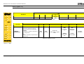
MI8 (Figure 12)
LED
ON
FAIL
SEL
IN
MEANING
RUN
IN
EXT
0
1
1
2
3
4
5
6
OFF
7
8
if the unit is waiting for the first
communication from the MASTER
RUN
IN FAIL
EXT FAIL
SEL
IN1÷8
GREEN
RED
RED
ORANGE
YELLOW
ON
ON
ON
ON
ON
Power on - initial TEST
Table 17 - Opening Screen
LED
MEANING
NORMAL
OPERATION
RUN
IN FAIL
EXT FAIL
SEL
IN1÷8
GREEN
RED
RED
ORANGE
YELLOW
FLASHES
if no INPUT or OUTPUT requested by the
configuration
ON
if INPUT or OUTPUT requested by the
configuration
OFF
OFF
ON
incorrect external
connection detected
INPUT condition
Shows the
NODE_SEL0/1 signal
table
only the number of the INPUT
with the incorrect connection
flashes
Table 18 - Dynamic Screen
English
Figure 12 - MI8
30
8540780 • 18th January 2011 • Rev.8
MODULAR SAFETY INTEGRATED CONTROLLER MOSAIC
MI16 (Figure 13)
LED
ON
FAIL
SEL
IN
RUN
IN
EXT
0
1
1
2
3
4
MEANING
RUN
IN FAIL
EXT FAIL
SEL
IN1÷16
GREEN
RED
RED
ORANGE
YELLOW
ON
ON
ON
ON
ON
Power on - initial TEST
Table 19 - Opening Screen
LED
5
6
7
8
9
10
11
12
13
14
15
16
MEANING
RUN
IN FAIL
EXT FAIL
SEL
IN1÷16
GREEN
RED
RED
ORANGE
YELLOW
OFF
if the unit is waiting for the first
communication from the MASTER
NORMAL
OPERATION
FLASHES
if no INPUT or OUTPUT requested by the
configuration
ON
if INPUT or OUTPUT requested by the
configuration
OFF
OFF
ON
incorrect external
connection detected
INPUT condition
Shows the
NODE_SEL0/1 signal
table
only the number of the INPUT
with the incorrect connection
flashes
Table 20 - Dynamic Screen
English
Figure 13 - MI16
8540780 • 18th January 2011 • Rev.8
31
MODULAR SAFETY INTEGRATED CONTROLLER MOSAIC
MO2 (Figure 14)
LED
FAIL
SEL
ON
RUN
IN
EXT
0
1
MEANING
Power on - initial TEST
RUN
IN FAIL
EXT FAIL
SEL
OSDD1/2
CLEAR1/2
STATUS1/2
GREEN
RED
RED
ORANGE
RED/GREEN
YELLOW
YELLOW
ON
ON
ON
ON
Red
ON
ON
Table 21 - Opening screen
LED
MEANING
RUN
IN FAIL
EXT FAIL
SEL
OSSD1/2
CLEAR1/2
STATUS1/2
GREEN
RED
RED
ORANGE
RED/GREEN
YELLOW
YELLOW
RED
with output
OFF
ON
waiting for
RESTART
OFF
if the unit is waiting for the first
communication from the MASTER
NORMAL
OPERATION
OSSD
CLEAR
STATUS
1
2
1
2
1
2
FLASHES
if no INPUT or OUTPUT requested by
the configuration
OFF
op. OK
OFF
op. OK
Shows the
NODE_SEL0/1 signal
table
ON
if INPUT or OUTPUT requested by the
configuration
GREEN
with output
ON
OUTPUT
condition
Flashes
NO feedback
Table 22 - Dynamic screen
English
Figure 14 - MO2
32
8540780 • 18th January 2011 • Rev.8
MODULAR SAFETY INTEGRATED CONTROLLER MOSAIC
MO4 (Figure 15)
LED
FAIL
SEL
ON
RUN
IN
EXT
0
1
MEANING
Power on - initial TEST
RUN
IN FAIL
EXT FAIL
SEL
OSDD1/4
CLEAR1/4
STATUS1/4
GREEN
RED
RED
ORANGE
RED/GREEN
YELLOW
YELLOW
ON
ON
ON
ON
Red
ON
ON
Table 23 - Opening screen
LED
OSSD
CLEAR
STATUS
MEANING
CLEAR
STATUS
IN FAIL
EXT FAIL
SEL
OSDD1/4
CLEAR1/4
STATUS1/4
RED
RED
ORANGE
RED/GREEN
YELLOW
YELLOW
RED
with output
OFF
ON
waiting for
RESTART
2
1
2
OFF
1
2
if the unit is waiting for the first
communication from the MASTER
NORMAL
OPERATION
OSSD
RUN
GREEN
1
3
4
3
4
3
4
FLASHES
if no INPUT or OUTPUT requested by
the configuration
OFF
op. OK
OFF
op. OK
Shows the
NODE_SEL0/1 signal
table
ON
if INPUT or OUTPUT requested by the
configuration
GREEN
with output
ON
OUTPUT
condition
Flashes
NO feedback
Table 24 - Dynamic screen
English
Figure 15 - MO4
8540780 • 18th January 2011 • Rev.8
33
MODULAR SAFETY INTEGRATED CONTROLLER MOSAIC
MR2 (Figure 16) / MR4 (Figure 17)
LED
OSSD1
MEANING
GREEN
NORMAL OPERATION
ON with output activated
Table 25 - MR2 - Dynamic screen
LED
MEANING
NORMAL OPERATION
OSSD1
OSSD2
GREEN
GREEN
ON with output activated
Table 26 - MR4 - Dynamic screen
OSSD
1
1
2
Figure 17 - MR4
English
Figure 16 - MR2
OSSD
34
8540780 • 18th January 2011 • Rev.8
MODULAR SAFETY INTEGRATED CONTROLLER MOSAIC
TROUBLESHOOTING
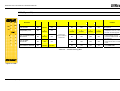
Master M1 (Figure 18)
LED
MEANING
ON
RUN
IN
EXT
COM
ENA
FAIL
Internal fault
Configuration
error
IN
OSSD
CLEAR
STATUS
1
2
3
4
5
6
7
8
1
2
1
2
1
2
Figure 18 - M1
OSSD output
error
REMEDY
RUN
IN FAIL
EXT FAIL
COM
IN1÷8
ENA
OSSD1/2
CLEAR1/2
STATUS1/2
GREEN
RED
RED
ORANGE
YELLOW
BLUE
RED/GREEN
YELLOW
YELLOW
OFF
2 or 3
flashes
OFF
OFF
OFF
OFF
Red
OFF
OFF
Return the unit to
ReeR to be repaired
5
flashes
• Upload the
project to the
MOSAIC again.
• If the problem
persists return
the M1 to ReeR to
be repaired
OFF
• Check the
OSSD1/2
connections
• If the problem
persists return
the M1 to ReeR to
be repaired
OFF
OFF
5
flashes
4
flashes
OFF
OFF
OFF
OFF
5 flashes
OFF
OFF
5
flashes
OFF
4 flashes
(only the LED
corresponding to the
output in FAIL mode)
5
flashes
OFF
Error in
communication
with slave
OFF
5
flashes
OFF
OFF
OFF
OFF
OFF
OFF
OFF
• Restart the
system.
• If the problem
persists return
the M1 to ReeR to
be repaired
Slave unit
error
OFF
ON
OFF
OFF
OFF
OFF
OFF
OFF
OFF
• Restart the
system
• Check which unit
is in FAIL mode
MCM error
OFF
6
flashes
OFF
6
flashes
OFF
OFF
OFF
OFF
OFF
Replace the MCM
8540780 • 18th January 2011 • Rev.8
English
Table 27 - Troubleshooting M1
35
MODULAR SAFETY INTEGRATED CONTROLLER MOSAIC
MI8O2 (Figure 19)
LED
MEANING
FAIL
SEL
IN
OSSD
CLEAR
STATUS
ON
RUN
IN
EXT
0
1
1
2
3
4
5
6
7
8
1
2
1
2
1
2
Internal fault
Compatibility error
OSSD output error
REMEDY
RUN
IN FAIL
EXT FAIL
SEL
IN1÷8
OSSD1/2
CLEAR1/2
STATUS1/2
GREEN
RED
RED
ORANGE
YELLOW
RED/GREEN
YELLOW
YELLOW
OFF
2 or 3
flashes
OFF
OFF
Red
OFF
OFF
Return the unit to ReeR
to be repaired
OFF
5
flashes
5 flashes
5
flashes
5
flashes
5
flashes
• Firmware version not
compatible with M1,
return to ReeR for FW
upgrade.
OFF
4 flashes
(only the LED
corresponding to the
output in FAIL mode)
OFF
• Check OSSD1/2
connections
• If the problem
persists, return the
MI8O2 to ReeR to be
repaired
OFF
4
flashes
OFF
OFF
Shows the
physical
address of the
unit
OFF
OFF
5
flashes
OFF
OFF
OFF
OFF
OFF
• Restart the system
• If the problem
persists, return the
MI8O2 to ReeR to be
repaired
Error on other
slave or M1
OFF
ON
OFF
OFF
OFF
OFF
OFF
• Restart the system
• Check which unit is in
FAIL mode
Same type of slave
with same address
detected
OFF
5
flashes
5
flashes
OFF
OFF
OFF
OFF
• Change the unit's
address (see NODE
SEL)
Error in
communication with
master
Table 28 - Troubleshooting MI8O2
English
Figure 19 - MI8O2
36
8540780 • 18th January 2011 • Rev.8
MODULAR SAFETY INTEGRATED CONTROLLER MOSAIC
MI8 (Figure 20)
ON
FAIL
SEL
IN
RUN
IN
EXT
0
1
1
2
3
4
5
6
7
8
LED
MEANING
REMEDY
RUN
IN FAIL
EXT FAIL
SEL
IN1÷8
OSSD1/2
CLEAR1/2
STATUS1/2
GREEN
RED
RED
ORANGE
YELLOW
RED/GREEN
YELLOW
YELLOW
Internal fault
OFF
2 or 3
flashes
OFF
OFF
Red
OFF
OFF
Compatibility error
OFF
5
flashes
OFF
5
flashes
5
flashes
5
flashes
5
flashes
Error in communication
with master
OFF
5
flashes
OFF
OFF
OFF
OFF
OFF
• Restart the system
• If the problem persists,
return the MI8 to ReeR to
be repaired
Error on other
slave or M1
OFF
ON
OFF
OFF
OFF
OFF
OFF
• Restart the system
• Check which unit is in FAIL
mode
Same type of slave with
same address detected
OFF
5
flashes
5
flashes
OFF
OFF
OFF
OFF
• Change the unit's address
(see NODE SEL)
Shows the
physical address
of the unit
Return the unit to ReeR to
be repaired
• Firmware version not
compatible with M1, return
to ReeR for FW upgrade.
Table 29 - Troubleshooting MI8
English
Figure 20 - MI8
8540780 • 18th January 2011 • Rev.8
37
MODULAR SAFETY INTEGRATED CONTROLLER MOSAIC
MI16 (Figure 21)
ON
LED
RUN
MEANING
FAIL
SEL
IN
IN
EXT
0
1
1
2
3
4
5
6
7
8
9
10
11
12
13
14
15
16
RUN
REMEDY
IN FAIL
EXT FAIL
SEL
IN1÷16
OSSD1/2
CLEAR1/2
STATUS1/2
GREEN
RED
RED
ORANGE
YELLOW
RED/GREEN
YELLOW
YELLOW
Internal fault
OFF
2 or 3
flashes
OFF
OFF
Red
OFF
OFF
Compatibility error
OFF
5
flashes
OFF
5
flashes
5
flashes
5
flashes
5
flashes
• Firmware version not
compatible with M1, return
to ReeR for FW upgrade.
Error in communication
with master
OFF
5
flashes
OFF
Error on other
slave or M1
OFF
ON
Same type of slave with
same address detected
OFF
5
flashes
Return the unit to ReeR to
be repaired
OFF
OFF
OFF
OFF
• Restart the system
• If the problem persists,
return the MI16 to ReeR to
be repaired
OFF
OFF
OFF
OFF
OFF
• Restart the system
• Check which unit is in FAIL
mode
5
flashes
OFF
OFF
OFF
OFF
• Change the unit's address
(see NODE SEL)
Shows the
physical address
of the unit
Table 30 - Troubleshooting MI16
English
Figure 21 - MI16
38
8540780 • 18th January 2011 • Rev.8
MODULAR SAFETY INTEGRATED CONTROLLER MOSAIC
MO2 / MO4 (Figure 22)
LED
MEANING
FAIL
SEL
ON
RUN
IN
EXT
0
1
FAIL
SEL
ON
RUN
IN
EXT
0
1
Internal fault
Compatibility error
OSSD
CLEAR
STATUS
OSSD
CLEAR
STATUS
1
2
1
2
1
2
OSSD
CLEAR
STATUS
1
2
1
2
3
4
3
4
3
4
Figure 22 - MO2 / MO4
IN FAIL
EXT FAIL
SEL
OSSD1/4
CLEAR1/2
STATUS1/2
GREEN
RED
RED
ORANGE
RED/GREEN
YELLOW
YELLOW
OFF
2 or 3
flashes
OFF
Red
OFF
OFF
Return the unit to ReeR
to be repaired
OFF
5
flashes
OFF
5
flashes
5
flashes
5
flashes
• Firmware version not
compatible with M1,
return to ReeR for FW
upgrade.
OFF
4 flashes
(only the LED
corresponding to the
output in FAIL mode)
OFF
• Check OSSD1/2
connections
• If the problem
persists, return the
MO2/4 to ReeR to be
repaired
2
1
OSSD output error
REMEDY
RUN
OFF
4
flashes
Shows the
physical
address of the
unit
OFF
Error in
communication with
master
OFF
5
flashes
OFF
OFF
OFF
OFF
• Restart the system
• If the problem
persists, return the
MI8O2 to ReeR to be
repaired
Error on other
slave or M1
OFF
ON
OFF
OFF
OFF
OFF
• Restart the system
• Check which unit is in
FAIL mode
Same type of slave
with same address
detected
OFF
5
flashes
5
flashes
OFF
OFF
OFF
• Change the unit's
address (see NODE
SEL)
English
Table 31 - Troubleshooting MO2/MO4
8540780 • 18th January 2011 • Rev.8
39
MODULAR SAFETY INTEGRATED CONTROLLER MOSAIC
MOSAIC SAFETY DESIGNER SOFTWARE
The "MOSAIC SAFETY DESIGNER" application software can be used to configure a logic
diagram of the connections between the MOSAIC (Master + expansions) and the
components of the system being developed.
The MOSAIC and its SLAVE units will thus monitor and control the connected safety
components.
The MSD uses a versatile graphic interface to establish the connections between the
various components, as described below:
Installing the software
PC HARDWARE requirements
• RAM: 256 MB
(adequate to run Windows XP SP3 + Framework 3.5)
• Hard disk: > 100Mbyte of free space
• USB connector: 1.1 or 2.0
• CD-ROM drive
PC SOFTWARE requirements
Î
Windows XP with Service Pack 3 installed (or higher OS).
Microsoft Framework 3.5 (or higher) must be installed on the PC
How to install MSD
• Insert the installation CD;
• Wait for the auto-run installer to request the SW setup program;
Alternatively follow the path D:/;
• Double-click on the SetupMSD.exe file;
When the installation procedure is complete a window is displayed asking you to
close the setup program.
40
8540780 • 18th January 2011 • Rev.8
MODULAR SAFETY INTEGRATED CONTROLLER MOSAIC
Fundamentals
Once the MSD has been correctly installed it creates an icon on the desktop.
To launch the program: double-click on this icon. =>
The opening screen shown below is displayed:
Figure 23
English
You are now ready to create your project.
8540780 • 18th January 2011 • Rev.8
41
MODULAR SAFETY INTEGRATED CONTROLLER MOSAIC
Standard tool bar
The standard tool bar is shown in Figure 24. The meanings of the icons are listed below:
1 ->
CREATE A NEW PROJECT
2 ->
CHANGE CONFIGURATION (composition of different modules)
3 ->
CHANGE USER PARAMETERS (name, company, etc)
4 ->
SAVE THE ACTUAL PROJECT
5 ->
LOAD AN EXISTING PROJECT
6 ->
PRINT THE PROJECT SCHEMATIC
7 ->
PRINT THE PROJECT REPORT
8 ->
VALIDATE THE PROJECT
9 ->
CONNECT TO MOSAIC
10 ->
SEND PROJECT TO MOSAIC
11 ->
DISCONNECT FROM MOSAIC
12 ->
MONITOR (Real time I/O status - graphic)
13 ->
MONITOR (Real time I/O status - textual)
14 ->
UPLOAD LOG FILE
15 ->
UPLOAD SYSTEM CONFIGURATION
16 ->
CHANGE PASSWORD
17 ->
ON-LINE HELP
English
Figure 24
42
8540780 • 18th January 2011 • Rev.8
MODULAR SAFETY INTEGRATED CONTROLLER MOSAIC
Create a new project (configure the MOSAIC system)
Select icon CREATE (Figure 24) from the standard tool bar to start a new project. The user
authentication window is displayed (Figure 25).
Figure 25
Next the MSD displays a window showing the M1 only.
You may add the various units needed to create your system, using the pull-down menus
at the top of the screen (select slave) and at the bottom to select the relative node (0÷3).
SELECT SLAVE (to add to your configuration)
SELECT NODE (from 0 to 3)
8540780 • 18th January 2011 • Rev.8
English
Figure 26
Select to disable MCM operations
43
MODULAR SAFETY INTEGRATED CONTROLLER MOSAIC
EDIT CONFIGURATION (composition of the various modules)
The change of the system composition is obtained with the icon
The configuration window is showed again (Figure 24).
.
Change user parameters
The change of user parameters is obtained with the icon
.
The dialog user identification request appears (Figure 27). To accomplish this operation is
not necessary to Log out from Mosaic. Generally it serves when a new user must create a
new project (even using a previously created).
English
Figure 27
44
8540780 • 18th January 2011 • Rev.8
MODULAR SAFETY INTEGRATED CONTROLLER MOSAIC
OBJECTS - OPERATOR - CONFIGURATION tool bars
Four large tool windows are displayed to the left and right of the main window
(shown in Figure 28):
1
2
3
Figure 28
4
1 > OBJECT TOOL WINDOW
This contains the various function blocks that will make up your project; these
blocks are divided into 3 different types:
- physical
- inputs
- outputs
- comments
2 > OPERATOR TOOL WINDOW
This contains the various function blocks for connecting the objects in point 1;
these blocks are divided into 5 different types:
- logical
- muting
- memories
- counters
- timers
English
3 > CONFIGURATION TOOL WINDOW
This contains the description of your project composition.
4 > CONFIGURATION TOOL WINDOW (view)
This contains the graphic representation of your project composition.
8540780 • 18th January 2011 • Rev.8
45
MODULAR SAFETY INTEGRATED CONTROLLER MOSAIC
Creating the diagram (Figure 16)
Once you have selected your system composition, you are ready to configure the project.
The logic diagram is created using a DRAG&DROP function:
• Select the objects as required from the windows described previously (each single
object is described in detail in the following sections) and drag it into the design area.
• Now when you select the object the PROPERTIES window is enabled, where you must
fill in the fields as required.
• When you need to set a specific numerical value with a slide (eg filter) use the left and
right arrows on your keyboard or click the sides of the slider of the slide.
• Connect the objects by moving the mouse over the required pin and then dragging it
onto the pin to be connected.
• If the scheme requires the PAN function (moving working area in the window), select
the object to move and use the arrow keys on your keyboard.
• When you need to delete an object or a link, select it and press DEL key on your
keyboard.
OBJECT
PROPERTIES
WINDOW
Connection
start point
DESIGN
AREA
English
Figure 29
46
8540780 • 18th January 2011 • Rev.8
MODULAR SAFETY INTEGRATED CONTROLLER MOSAIC
Example of a project
Figure 30 shows an example of a project in which the M1 unit only is connected to two
safety blocks (E-GATE and E-STOP).
The M1 inputs (1,2,3) for connecting the contacts of the safety components are shown on
the left, in yellow. The MOSAIC outputs (from 1 to 4) are activated according to the
conditions defined in E-GATE and E-STOP (see the E-GATE - E-STOP sections).
By clicking on a block to select it, you enable the PROPERTIES WINDOW on the right, which
you can use to configure the block activation and test parameters (see the
E-GATE - E-STOP sections).
Figure 30
At the end of the project design stage (or at intermediate steps) you can save the current
configuration using the icon SAVE on the standard tool bar.
Project validation
Î
Now the finished project must be verified. Execute the VALIDATE command (Icon
on the standard toolbar).
If the validation is successful, a sequential number is assigned to the input and output of
the project. Then, this number is also listed in the REPORT and in the MONITOR of MSD.
Only if the validation is successful we will proceed to send the configuration.
Print of the System composition with properties of each block. (Icon
toolbar).
8540780 • 18th January 2011 • Rev.8
on the standard
47
English
Project report
MODULAR SAFETY INTEGRATED CONTROLLER MOSAIC
Connect to Mosaic
After connecting M1 to the PC via CSU cable (USB) use the icon
for the connection.
A window appears to request the password. Enter the password (see "Password
protection").
Figure 31
Sending the configuration to the MOSAIC
To send the saved configuration from a PC to M1 use the icon
on the standard
toolbar and wait the execution. M1 will save the project in its internal memory and
(if present) in MCM memory. (Password Required: level 2).
Î
This function is possible only after the project validation.
Configuration LOG
Î
Within the configuration file (project), are included the creation date and CRC
(4-digit hexadecimal identification) of a project that are stored in M1.
Î
This logbook can record up to 5 consecutive events, after which these are
overwritten, starting from the least recent event.
The log file can be visualized using the icon
(Password Required: level 1).
in the standard tool bar.
English
Figure 32
48
8540780 • 18th January 2011 • Rev.8
MODULAR SAFETY INTEGRATED CONTROLLER MOSAIC
Upload system configuration
The check of the actual composition of the MOSAIC system is obtained using the icon
. (Password Required: level 1). A pop-up window will appear with:
- Connected modules;
- Firmware version of each module;
- Node number (physical address) of each module.
Figura 33
Disconnecting System
To disconnect the PC from M1 use the icon
resetted and it starts with the sent project.
Î
; when the system is disconnected it is
If the system is not composed of all modules provided by the configuration, after
the disconnection, M1 indicates the incongruity and does not starts. (See SIGNALS).
MONITOR (I/O status in real time - textual)
English
To activate the monitor use the icon
. (Password Required: level 1).
A pop-up window will appear (in real time) with:
- Status of the inputs (when the object has two or more input connections to Mosaic, the
MONITOR will show as active only the first), see the example in figure;
- Inputs Diagnostics;
- OSSD State;
- OSSD Diagnostics;
- Status of digital outputs;
- OUT TEST diagnostics.
Figure 34 - textual monitor
8540780 • 18th January 2011 • Rev.8
49
MODULAR SAFETY INTEGRATED CONTROLLER MOSAIC
MONITOR (I/O status in real time - textual - graphic)
To activate/deactivate the monitor use the icon
. (Password Required: level 1).
The color of links (Figure 33) allows you to view the diagnostics (in real time) with:
RED = OFF
GREEN = ON
DASHED ORANGE = Connection Error
DASHED RED = Pending enable (for example RESTART)
Placing the mouse pointer over the link, you can display the diagnostics.
English
Figure 35 - graphic monitor
50
8540780 • 18th January 2011 • Rev.8
MODULAR SAFETY INTEGRATED CONTROLLER MOSAIC
Password protection
The MSD requests a password in order to upload and save the project.
Level 1 password
All operators using the M1 system must have a Level 1 PASSWORD.
This Password allows only to view the LOG file, composition of the system and MONITOR
in real time.
The first time the system is initialised the operator must use the password "" (ENTER key).
Designers who know the level 2 password can enter a new level 1 password
(alphanumerical, max 8 characters).
Î
Operators who know this password are not enabled to upload, modify or save the
project.
Level 2 password
Designers authorised to work on the creation of the project must know a Level 2
PASSWORD. The first time the system is initialised the operator must use the password
"SAFEPASS" (all capital letters).
Designers who know the level 2 password can enter a new level 2 password
(alphanumerical, max 8 characters).
Î
This password enables the project to be uploaded, modified and saved. In other
words, it allows total control of the PC => MOSAIC system.
Î
Î
When a new project is UPLOADED the level 2 password could be changed.
Should you forget either of these passwords, please contact REER which will provide
an unlock file (when the unlock file is saved in the right directory the icon
will
appear on the toolbar). When the icon is activated, the password level 1 and level 2
are restored to their original values. This password is only given to the designer and
can only be used once.
Password Change
English
To activate the PASSWORD Change use icon
, after connecting with Level 2 Password.
A window appears (Figure 36) allowing the choice of the new password; insert the old and
new passwords in the appropriate fields (max 8 characters). Click OK.
At the end of the operation disconnect to restart the system.
If MCM is present the new password is also saved in it.
Figure 36
8540780 • 18th January 2011 • Rev.8
51
MODULAR SAFETY INTEGRATED CONTROLLER MOSAIC
TESTING the system
After
validating and uploading the project to the M1 and connecting all the safety
devices, you must test the system to verify its correct operation.
This is done by forcing a change of status for each safety device connected to the
MOSAIC to check that the status of the outputs actually changes.
The following example is helpful for understanding the TEST procedure.
Figure 37
(t1) In the normal operating condition (E-GATE closed) Input1 is closed, Input2 is
open and the output of the E-GATE block is set to high logic level; in this mode
the safety outputs (OSSD1/2) are active and the power supply to the relative
terminals is 24VDC.
(t2) When the E-GATE is physically opened, the condition of the inputs and thus of
the outputs of the E-GATE block will change: (OUT= 0VDC--->24VDC); the
condition of the OSSD1-OSSD2 safety outputs will change from 24VDC to
0VDC. If this change is detected the mobile E-GATE is connected correctly.
In1
24vdc
0vdc
In2
0vdc
24vdc
Output
24vdc
OSSD1
24vdc
0vdc
OSSD2
24vdc
0vdc
(t1)
(t2)
For
English
the correct installation of each external sensor/component refer to their
installation manual.
This test must be performed for each safety component in the project.
52
8540780 • 18th January 2011 • Rev.8
MODULAR SAFETY INTEGRATED CONTROLLER MOSAIC
OBJECT FUNCTION BLOCKS
OUTPUT OBJECTS
OSSD (safety outputs)
The OSSD semiconductor safety outputs require no
maintenance, Output1 and Output2 supply 24Vdc if
the input is 1 (TRUE), whereas they supply 0Vdc if
the input is 0 (FALSE).
Î
Each pair of OSSD has an entrance on
RESTART_FBK. This input must always be
connected
as
described
in
paragraph
RESTART_FBK.
Parameters
Enabled reset: If selected this enables the request to reset each time the input signal falls.
Otherwise, enabling of the output directly follows the input conditions.
There are two types of reset: Manual and Monitored. When Manual is selected the system
only verifies the signal's transition from 0 to 1. If Monitored is selected the double
transition from 0 to 1 and then back to 0 is verified.
Enable status: If checked enables the connection of the current status of the OSSD with a
STATUS.
STATUS (signal output)
English
STATUS output (NOT SAFETY OUTPUT) makes it
possible to monitor any point on the diagram by
connecting it to the input. The output returns 24Vdc if
the input is 1 (TRUE), or 0Vdc if the input is 0 (FALSE).
WARNING: The STATUS output is NOT a safety output.
8540780 • 18th January 2011 • Rev.8
53
MODULAR SAFETY INTEGRATED CONTROLLER MOSAIC
INPUT OBJECTS
E-STOP (emergency stop)
E-STOP function block verifies an emergency stop
device inputs status. If the emergency stop button
has been pressed the output is 0 (FALSE). If not the
output is 1 (TRUE).
Parameters
Input type:
- Single NC – allows connection of one-way
emergency stops
- Double NC – allows connection of two-way
emergency stops .
Enabled reset: If selected this enables the request to
reset each time the emergency stop is activated.
Otherwise, enabling of the output directly follows
the input conditions.
There are two types of reset: Manual and Monitored. When Manual is selected the system
only verifies the signal's transition from 0 to 1. If Monitored is selected the double
transition from 0 to 1 and then back to 0 is verified.
English
Î
WARNING: If the Enabled Reset is active, a consecutive Input have to be used.
Example : Input 1 and Input 2 are used for the fuctional block, then Input 3 have to
be used for the Reset Input.
Output test: This is used to select which test output signals are to be sent to the
emergency stop (mushroom pushbutton). This additional test makes it possible to detect
and manage any short-circuits between the lines. There is a choice of 4 possible test
output signals, Test Output 1 ÷ Test Output 4.
Test at start-up: If selected this enables the test at start-up of the external component
(emergency stop). This test is performed by pressing and releasing the pushbutton to run
a complete function test and enable the output. This test is only requested at machine
start-up (when the unit is switched on).
54
8540780 • 18th January 2011 • Rev.8
MODULAR SAFETY INTEGRATED CONTROLLER MOSAIC
Filter (ms): This is used to filter the signals coming from the emergency stop. The filter
can be configured to between 3 and 250 ms and eliminates any bouncing on the
contacts. The length of the filter affects the calculation of the unit's total response time.
Concurrent enable: If selected this activates the test to verify concurrent switching of the
signals coming from the emergency stop.
Concurrent (ms): This is only active if the previous parameter is enabled. It defines the
maximum time (in msecs) between the switching of two different signals from the
emergency stop.
Object description: This allows a description of the component's function to be entered.
The text is displayed in the top part of the symbol.
E-GATE (safety gate device)
E-GATE function block verifies a mobile guard or
safety gate device input status. If the mobile
guard or safety gate is open, the output is 0
(FALSE). Otherwise the output is 1 (TRUE).
Parameters
English
Input type:
- Double NC – Allows connection of
components with two NC contacts
- Double NC/NO – Allows connection of
components with one NO contact and one
NC.
Enable reset: If selected this enables the request
to reset each time the mobile guard/safety gate
is activated. Otherwise, enabling of the output
directly follows the input conditions.
There are two types of reset: Manual and
Monitored. When Manual is selected the system
only verifies the signal's transition from 0 to 1.
If Monitored is selected the double transition
from 0 to 1 and then back to 0 is verified.
8540780 • 18th January 2011 • Rev.8
55
MODULAR SAFETY INTEGRATED CONTROLLER MOSAIC
Î
WARNING: If the Enabled Reset is active, a consecutive Input have to be used.
Example : Input 1 and Input 2 are used for the fuctional block, then Input 3 have to
be used for the Reset Input.
Output test: This is used to select which test output signals are to be sent to the
component contacts. This additional test makes it possible to detect and manage any
short-circuits between the lines. There is a choice of 4 possible test output signals, Test
Output 1 ÷ Test Output 4.
Test at start-up: If selected this enables the test at start-up of the external component.
This test is performed by opening the mobile guard or safety gate to run a complete
function test and enable the output. This test is only requested at machine start-up (when
the unit is switched on).
Filter (ms): This is used to filter the signals coming from the external contacts. The filter
can be configured to between 3 and 250 ms and eliminates any bouncing on the
contacts. The length of the filter affects the calculation of the unit's total response time.
Concurrent enable: If selected this activates the test to verify concurrent switching of the
signals coming from the external contacts.
Concurrent (ms): This is only active if the previous parameter is enabled. It defines the
maximum time (in msecs) between the switching of two different signals from the
external contacts.
Object description: This allows a description of the component's function to be entered.
The text is displayed in the top part of the symbol.
ENABLE (enable key)
ENABLE function block verifies a manual key
device Input status. If the key is not turned the
output is 0 (FALSE). Otherwise the output is 1
(TRUE).
Parameters
Input type
- Single NO – Allows connection of
components with one NO contact;
- Double NO – Allows connection of
components with two NO contacts.
English
Enable reset: If selected this enables the
request to reset each time the command is
activated. Otherwise, enabling of the output
directly follows the input conditions.
There are two types of reset: Manual and
Monitored. When Manual is selected the system
only verifies the signal's transition from 0 to 1.
If Monitored is selected the double transition
from 0 to 1 and then back to 0 is verified.
Î
56
WARNING: If the Enabled Reset is active, a consecutive Input have to be used.
Example : Input 1 and Input 2 are used for the fuctional block, then Input 3 have to
be used for the Reset Input.
8540780 • 18th January 2011 • Rev.8
MODULAR SAFETY INTEGRATED CONTROLLER MOSAIC
Output test: This is used to select which test output signals are to be sent to the
component contacts. This additional test makes it possible to detect and manage any
short-circuits between the lines. There is a choice of 4 possible test output signals, Test
Output 1 ÷ Test Output 4.
Test at start-up: If selected this enables the test at start-up of the external component.
This test is performed by opening and activating the enable key to run a complete
function test and enable the output. This test is only requested at machine start-up (when
the unit is switched on).
Filter (ms): This is used to filter the signals coming from the external contacts. The filter
can be configured to between 3 and 250 ms and eliminates any bouncing on the
contacts. The length of the filter affects the calculation of the unit's total response time.
Concurrent enable: If selected this activates the test to verify concurrent switching of the
signals coming from the external contacts.
Concurrent (ms): This is only active if the previous parameter is enabled. It defines the
maximum time (in msecs) between the switching of two different signals from the
external contacts.
Object description: This allows a description of the component's function to be entered.
The text is displayed in the top part of the symbol.
ESPE (optoelectronic safety light curtain / laser scanner)
ESPE function block verifies an optoelectronic
safety light curtain (or laser scanner) inputs
state. If the area protected by the light curtain
is occupied, (light curtain outputs FALSE) the
output is 0 (FALSE). Otherwise, with the area
clear and outputs to 1 (TRUE) the output is 1
(TRUE).
Parameters
8540780 • 18th January 2011 • Rev.8
English
Enable reset: If selected this enables the
request to reset each time the area protected
by the safety light curtain is occupied.
Otherwise, enabling of the output directly follows the input conditions.
57
MODULAR SAFETY INTEGRATED CONTROLLER MOSAIC
There are two types of reset: Manual and Monitored. When Manual is selected the system
only verifies the signal's transition from 0 to 1. If Monitored is selected the double
transition from 0 to 1 and then back to 0 is verified.
Î
WARNING: If the Enabled Reset is active, a consecutive Input have to be used.
Example : Input 1 and Input 2 are used for the fuctional block, then Input 3 have to
be used for the Reset Input.
OUT TEST signals cannot be used in case of safety static output ESPE because the control
is carried out from the ESPE.
Test at start-up: If selected this enables the test at start-up of the safety light curtain.
This test is performed by occupying and clearing the area protected by the safety light
curtain to run a complete function test and enable the output. This test is only requested
at machine start-up (when the unit is switched on).
Filter (ms): This is used to filter the signals coming from the safety light curtain. The filter
can be configured to between 3 and 250 ms and eliminates any bouncing on the
contacts. The length of the filter affects the calculation of the unit's total response time.
Concurrent enable: If selected this activates the test to verify concurrent switching of the
signals coming from the safety light curtain.
Concurrent (ms): This is only active if the previous parameter is enabled. It defines the
maximum time (in msecs) between the switching of two different signals from the safety
light curtain.
English
Object description: This allows a description of the component's function to be entered.
The text is displayed in the top part of the symbol.
58
8540780 • 18th January 2011 • Rev.8
MODULAR SAFETY INTEGRATED CONTROLLER MOSAIC
FOOTSWITCH (safety pedal)
The FOOTSWITCH function block verifies the
status of the inputs of a safety pedal device. If
the pedal is not pressed the output is 0
(FALSE). Otherwise the output is 1 (TRUE).
Parameters
Input type:
- Single NC – Allows connection of pedals
with one NC contact
- Single NO – Allows connection of pedals
with one NO contact.
- Double NC – Allows connection of pedals
with two NC contacts
- Double NC/NO – Allows connection of
pedals with one NO contact and one NC.
Enabled reset: If selected this enables the
request to reset each time the safety pedal is
activated. Otherwise, enabling of the output
directly follows the input conditions.
There are two types of reset: Manual and Monitored. When Manual is selected the system
only verifies the signal's transition from 0 to 1. If Monitored is selected the double
transition from 0 to 1 and then back to 0 is verified.
WARNING: If the Enabled Reset is active, a consecutive Input have to be used.
Example : Input 1 and Input 2 are used for the fuctional block, then Input 3 have to
be used for the Reset Input.
Output test: This is used to select which test output signals are to be sent to the
component contacts. This additional test makes it possible to detect and manage any
short-circuits between the lines. There is a choice of 4 possible test output signals, Test
Output 1 ÷ Test Output 4.
Test at start-up: If selected this enables the test at start-up of the external component.
This test is performed by pressing and releasing the footswitch to run a complete
function test and enable the output. This test is only requested at machine start-up (when
the unit is switched on).
8540780 • 18th January 2011 • Rev.8
59
English
Î
MODULAR SAFETY INTEGRATED CONTROLLER MOSAIC
Filter (ms): This is used to filter the signals coming from the external contacts. The filter
can be configured to between 3 and 250 ms and eliminates any bouncing on the
contacts. The length of the filter affects the calculation of the unit's total response time.
Concurrent enable: If selected this activates the test to verify concurrent switching of the
signals coming from the external contacts.
Concurrent (ms): This is only active if the previous parameter is enabled. It defines the
maximum time (in msecs) between the switching of two different signals from the
external contacts.
Object description: This allows a description of the component's function to be entered.
The text is displayed in the top part of the symbol.
MOD-SEL (safety selector)
The MOD-SEL function block verifies the status
of the inputs from a mode selector (up to 4
inputs): If only one input is 1 (TRUE) the
corresponding output is also 1 (TRUE). In all
other cases, and thus when all inputs are 0
(FALSE) or more than one input is 1 (TRUE) all
the outputs are 0 (FALSE)
Parameters
Input type:
- Double selector – Allows connection of two-way mode selectors.
- Triple selector – Allows connection of three-way mode selectors.
- Quadruple selector - Allows connection of four-way mode selectors.
Filter (ms): This is used to filter the signals coming from the mode selector. The filter can
be configured to between 3 and 250 ms and eliminates any bouncing on the contacts.
The length of the filter affects the calculation of the unit's total response time
Object description: This allows a description of the component's function to be entered.
The text is displayed in the top part of the symbol.
PHOTOCELL (safety photocell)
The PHOTOCELL function block verifies the
status of the inputs of an optoelectronic safety
photocell. If the beam of the photocell is
occupied (photocell output FALSE) the output is
0 (FALSE). Otherwise with the beam clear and an
output of 1 (TRUE) the output is 1 (TRUE).
English
Parameters
Enabled reset: If selected this enables the
request to reset each time safety photocell is
activated. Otherwise, enabling of the output
directly follows the input conditions.
There are two types of reset: Manual and
Monitored. When Manual is selected the system
only verifies the signal's transition from 0 to 1. If Monitored is selected the double
transition from 0 to 1 and then back to 0 is verified.
60
8540780 • 18th January 2011 • Rev.8
MODULAR SAFETY INTEGRATED CONTROLLER MOSAIC
Î
WARNING: If the Enabled Reset is active, a consecutive Input have to be used.
Example : Input 1 is used for the fuctional block, then Input 2 have to be used for
the Reset Input.
Output test: This is used to select which test output are to be sent to the photocell test
input. This additional test makes it possible to detect and manage any short-circuits
between the lines. One test signal is mandatory and can be chosen among the four
possible test output signals: Test Output 1 ÷ Test Output 4.
Test at start-up: If selected this enables the test at start-up of the external component.
This test is performed by occupying and clearing the photocell to run a complete function
test and enable the output. This test is only requested at machine start-up (when the unit
is switched on).
Filter (ms): This is used to filter the signals coming from the external contacts. The filter
can be configured to between 3 and 250 ms and eliminates any bouncing on the
contacts. The length of the filter affects the calculation of the unit's total response time.
Object description: This allows a description of the component's function to be entered.
The text is displayed in the top part of the symbol.
TWO-HAND (bimanual control)
The TWO HAND function block verifies the
status of the inputs of a two hand control
switch. Only if both the press-buttons are
pressed within 500 msec the output is 1 (TRUE).
Otherwise the output is 0 (FALSE).
Output test: This is used to select which test
output signals are to be sent to the component
contacts. This additional test makes it possible
to detect and manage any short-circuits between the lines. There is a choice of 4 possible
test output signals, Test Output 1 ÷ Test Output 4.
Test at start-up: If selected this enables the test at start-up of the external component.
This test is performed by pressing the two buttons (within 500 msec) and releasing them
to run a complete function test and enable the output. This test is only requested at
machine start-up (when the unit is switched on).
8540780 • 18th January 2011 • Rev.8
61
English
Input type:
- Double NO – Allows connection of two-hand
switch with one NO contact for each button.
- Quadruple NC-NO - Allows connection of twohand switch with a double NO/NC contact for
each button.
MODULAR SAFETY INTEGRATED CONTROLLER MOSAIC
Filter (ms): This is used to filter the signals coming from the mode selector. The filter can
be configured to between 3 and 250 ms and eliminates any bouncing on the contacts.
The length of the filter affects the calculation of the unit's total response time
Item description: This allows a description of the component's function to be entered. The
text is displayed in the top part of the symbol.
SENSOR
The SENSOR function block verifies the status of
the input of a sensor (not a safety sensor). If the
beam of the sensor is occupied (sensor output
FALSE) the output is 0 (FALSE). Otherwise, with
the beam clear and an output of 1 (TRUE) then
the output is 1 (TRUE).
Parameters
Enabled reset: If selected this enables the
request to reset each time the area protected by
the sensor is occupied. Otherwise, enabling of
the output directly follows the input conditions.
There are two types of reset: Manual and
Monitored. When Manual is selected the system
only verifies the signal's transition from 0 to 1. If
Monitored is selected the double transition from 0 to 1 and then back to 0 is verified.
Î
WARNING: If the Enabled Reset is active, a consecutive Input have to be used.
Example : Input 1 is used for the fuctional block, then Input 2 have to be used for
the Reset Input.
Output test: This is used to select which test output signals are to be sent to the
sensor. This additional test makes it possible to detect and manage any short-circuits
between the lines. There is a choice of 4 possible test output signals, Test Output 1 ÷
Test Output 4.
English
Test at start-up: If selected this enables the test at start-up of the sensor. This test is
performed by occupying and clearing the area protected by the sensor to run a complete
function test and enable the output. This test is only requested at machine start-up (when
the unit is switched on).
Filter (ms): This is used to filter the signals coming from the sensor. The filter can be
configured to between 3 and 250 ms and eliminates any bouncing on the contacts. The
length of the filter affects the calculation of the unit's total response time.
Object description: This allows a description of the component's function to be entered.
The text is displayed in the top part of the symbol.
62
8540780 • 18th January 2011 • Rev.8
MODULAR SAFETY INTEGRATED CONTROLLER MOSAIC
S-MAT (safety mat)
The S-MAT function block verifies the status of
the inputs of a safety mat. If a person stands
on the mat the output is 0 (FALSE). Otherwise,
with the mat clear, the output is 1 (TRUE).
Parameters
Enabled reset: If selected this enables the
request to reset each time the mobile
guard/safety gate is activated. Otherwise,
enabling of the output directly follows the
input conditions.
There are two types of reset: Manual and
Monitored. When Manual is selected the system
only verifies the signal's transition from 0 to 1.
If Monitored is selected the double transition
from 0 to 1 and then back to 0 is verified.
Î
If the Enabled Reset is active, a consecutive Input have to be used. Example : Input 1
and Input 2 are used for the fuctional block, then Input 3 have to be used for the
Reset Input.
Î
Each output OUT TEST can be connected to only one input S-MAT (it is not allowed
parallel connection of 2 inputs).
Î
The function block S-MAT can not be used with 2-wire components and termination
resistance.
Output test: This is used to select which test output signals are to be sent to the mat
contact. This additional test makes it possible to detect and manage any short-circuits
between the lines. Test signals are mandatory and must be chosen between two possible
configurations: Test Output 1/Test Output 2 or Test Output 3/Test Output 4.
Filter (ms): This is used to filter the signals coming from the external contacts. The filter
can be configured to between 3 and 250 ms and eliminates any bouncing on the
contacts. The length of the filter affects the calculation of the unit's total response time.
8540780 • 18th January 2011 • Rev.8
63
English
Test at start-up: If selected this enables the test at start-up of the external component.
This test is performed by pressing and releasing the safety mat to run a complete
function test and enable the output. This test is only requested at machine start-up (when
the unit is switched on).
MODULAR SAFETY INTEGRATED CONTROLLER MOSAIC
Object description: This allows a description of the component's function to be entered.
The text is displayed in the top part of the symbol.
SWITCH
SWITCH function block verifies the input status
of a pushbutton or switch (NOT SAFETY
SWITCHES). If the pushbutton is pressed the
output is 1 (TRUE). Otherwise, the output is 0
(FALSE).
Parameters
Enabled reset: If selected this enables the
request to reset each time the area protected by
the safety light curtain is occupied. Otherwise,
enabling of the output directly follows the input
conditions.
There are two types of reset: Manual and
Monitored. When Manual is selected the system
only verifies the signal's transition from 0 to 1. If
Monitored is selected the double transition from
0 to 1 and then back to 0 is verified.
Î
WARNING: If the Enabled Reset is active, a consecutive Input have to be used.
Example : Input 1 is used for the fuctional block, then Input 2 have to be used for
the Reset Input.
Output test: This is used to select which test output signals are to be sent to the switch. This
additional test makes it possible to detect and manage any short-circuits between the lines.
There is a choice of 4 possible test output signals, Test Output 1 ÷ Test Output 4.
English
Test at start-up: If selected this enables the test at start-up of the switch. This test is
performed by opening and closing the switch contact to run a complete function test and
enable the output. This test is only requested at machine start-up (when the unit is
switched on).
Filter (ms): This is used to filter the signals coming from the switch. The filter can be
configured to between 3 and 250ms and eliminates any bouncing on the contacts. The
length of the filter affects the calculation of the unit's total response time.
Object description: This allows a description of the component's function to be entered.
The text is displayed in the top part of the symbol.
64
8540780 • 18th January 2011 • Rev.8
MODULAR SAFETY INTEGRATED CONTROLLER MOSAIC
COMMENTS
This allows a description to be entered and placed
in any point of the diagram.
TITLE
Automatically adds the name of the
manufacturer, the designer, the project
name and the CRC.
OPERATOR FUNCTION BLOCKS
All the input of these operators could be inverted (logical NOT). It could be done clicking
with the right mouse key on the input to be inverted. A little circle will be showed on the
inverted input. To cancel the inversion, simply click another time on the same input pin.
Î
The maximum number of user blocks is 32.
LOGICAL OPERATORS
AND
Logical AND returns an output of 1 (TRUE) if
all the inputs are 1 (TRUE).
In1
0
1
0
1
0
1
0
1
In2
0
0
1
1
0
0
1
1
Inx
0
0
0
0
1
1
1
1
Out
0
0
0
0
0
0
0
1
Parameters
English
Number of inputs: this is used to set between 2 and 8 inputs.
8540780 • 18th January 2011 • Rev.8
65
MODULAR SAFETY INTEGRATED CONTROLLER MOSAIC
NAND
Logical NAND returns an output of 0 (FALSE) if
all the inputs are 1 (TRUE).
In1
0
1
0
1
0
1
0
1
In2
0
0
1
1
0
0
1
1
Inx
0
0
0
0
1
1
1
1
Out
1
1
1
1
1
1
1
0
Parameters
Number of inputs: this is used to set between 2 and 8 inputs.
NOT
Logical NOT inverts the logical status of the
input.
In
0
1
Out
1
0
OR
Logical OR returns an output of 1 (TRUE) if at
least one of the inputs is 1 (TRUE).
In1
0
1
0
1
0
1
0
1
In2
0
0
1
1
0
0
1
1
Inx
0
0
0
0
1
1
1
1
Out
0
1
1
1
1
1
1
1
Parameters
English
Number of inputs: this is used to set between 2 and 8 inputs.
66
8540780 • 18th January 2011 • Rev.8
MODULAR SAFETY INTEGRATED CONTROLLER MOSAIC
NOR
Logical NOR returns an output of 0 (FALSE) if
at least one of the inputs is 1 (TRUE).
In1
0
1
0
1
0
1
0
1
In2
0
0
1
1
0
0
1
1
Inx
0
0
0
0
1
1
1
1
Out
1
0
0
0
0
0
0
0
Parameters
Number of inputs: this is used to set between 2 and 8 inputs.
XOR
Logical XOR returns an output 0 (FALSE) if the
input's number at 1 (TRUE) is even or the
inputs are all 0 (FALSE).
In1
0
1
0
1
0
1
0
1
In2
0
0
1
1
0
0
1
1
Inx
0
0
0
0
1
1
1
1
Out
0
1
1
0
1
0
0
1
Parameters
Number of inputs: this is used to set between 2 and 8 inputs.
XNOR
Logical XNOR returns an output 1 (TRUE) if the
input's number at 1 (TRUE) is even or the
inputs are all 0 (FALSE).
In2
0
0
1
1
0
0
1
1
Inx
0
0
0
0
1
1
1
1
Out
1
0
0
1
0
1
1
0
English
In1
0
1
0
1
0
1
0
1
Parameters
Number of inputs: this is used to set between 2 and 8 inputs.
8540780 • 18th January 2011 • Rev.8
67
MODULAR SAFETY INTEGRATED CONTROLLER MOSAIC
MULTIPLEXER
Logical MULTIPLEXER forwards the signal of
the inputs to the output according to the Sel
selection. If the SEL1÷SEL4 have only one bit
set, the selected In n is connected to the
Output. If the SEL inputs are:
- more than one = 1 (TRUE)
- none = 1 (TRUE)
the output is set to 0 (FALSE) independently
from the In n values.
Parameters
Number of inputs: this is used to set between 2 and 4 inputs.
MEMORY OPERATORS
MEMORY operators can be used if you decide to save any data (TRUE or FALSE) from other
project components.
Status changes are performed according to the truth tables shown for each operator.
D FLIP FLOP (max number = 8)
The D FLIP FLOP operator saves the previously
set status on output Q according to the
following truth table.
Preset Clear
Ck
1
0
X
0
1
X
1
1
X
0
0
L
0
0
Rising edge
0
0
Rising edge
D
Q
X
1
X
0
X
0
X Keep memory
1
1
0
0
Parameters
Preset: If selected enables output Q to be set to 1 (TRUE).
English
Clear: If selected enables the saving process to be reset.
68
8540780 • 18th January 2011 • Rev.8
MODULAR SAFETY INTEGRATED CONTROLLER MOSAIC
SR FLIP FLOP
SR FLIP FLOP operator brings output Q at 1
with Set, 0 with Reset.
See the following truth table.
SET RESET
Q
0
0
Keep memory
0
1
0
1
0
1
1
1
0
USER RESTART MANUAL (max number = 8 with RESTART MONITORED)
The USER RESTART MANUAL operator saves
the restart signal according to the following
truth table.
Clear
Restart
1
X
X
X
0
L
0
Rising edge
0
Falling edge
In
Q
X
0
0
0
1 Keep memory
1
1
1 Keep memory
Parameters
Clear enable: If selected enables the saving process to be reset.
USER RESTART MONITORED (max number = 8 with RESTART MANUAL)
The USER RESTART MONITORED operator is
used to save the restart signal according to
the following truth table.
Clear
Restart
1
X
X
X
0
L
0
Rising edge
0
In
Q
X
0
0
0
1 Keep memory
1 Keep memory
1
1
English
Parameters
Clear enable: If selected enables the saving process to be reset.
8540780 • 18th January 2011 • Rev.8
69
MODULAR SAFETY INTEGRATED CONTROLLER MOSAIC
COUNTER OPERATORS
COUNTER operator is a pulse counter that sets output Q to 1 (TRUE) as soon as the
desired count is reached.
COUNTER (max number = 8).
The operator COUNTER is a pulse counter.
There are 3 operationg modes:
1) AUTOMATIC
2) MANUAL
3) AUTOMATIC + MANUAL
1) The counter generates a pulse duration
equal to the system response time as soon
as the set count is reached. If the CLEAR
pin is not enabled this is the default mode.
2) The counter leads to 1 (TRUE) the output Q
as soon as it reaches the set count. The
output Q goes to 0 (FALSE) when the
signal CLEAR is activated.
3) The counter generates a pulse duration equal to the system response time as soon as the
set count is reached. If the CLEAR signal is activated, the internal count goes back to 0.
Parameters
Clear Enable: If selected this enables the request to clear in order to restart the counter
setting output Q to 0 (FALSE). It also offers the possibility of enabling or not enabling
(Automatic Enable) automatic operation with manual reset.
If this is not selected operation is automatic. Once the set count is reached output Q is
set to 1(TRUE) and stays in this condition for two internal cycles after which it is resetted.
Ck down: Enables counting down.
Two-way: If selected it enables counting on both the rising and falling edges.
TIMER OPERATORS (max number = 8)
TIMER operators allow you to generate a signal (TRUE or FALSE) for a user-definable
period.
CLOCKING
CLOCKING operator generates a clock signal
output with the desired period if the input In is
1 (TRUE).
English
Parameters
Time: The period can be set to between 10 ms
and 1093.3 s.
70
8540780 • 18th January 2011 • Rev.8
MODULAR SAFETY INTEGRATED CONTROLLER MOSAIC
MONOSTABLE
The MONOSTABILE operator generates a
level 1 (TRUE) output activated by the rising
edge of the input and remains in this
condition for the set time.
Parameters
Time: The delay can be set to between 10 ms
and 1093.3 s.
Rising edge: If selected, the output is set to 1 (TRUE) on the input signal's rising edge
where it remains for the set time, which can be extended for as long as the input stays at
1 (TRUE).
In
T
T
T
Out
If not selected the logic is inverted, the output is set to 0 (FALSE) on the input signal's
falling edge, where it remains for the set time, which can be extended for as long as the
input stays at 0 (FALSE).
In
T
T
T
Out
English
Retriggerable: If selected the time is reset each time the input status changes.
8540780 • 18th January 2011 • Rev.8
71
MODULAR SAFETY INTEGRATED CONTROLLER MOSAIC
PASSING MAKE CONTACT
In the PASSING MAKE CONTACT operator the
output follows the signal on the input.
However, if this is 1 (TRUE) for longer than the
set time, the output changes to 0 (FALSE).
When there is an input falling edge, the timer
is cleared.
Parameters
Time: The delay can be set to between 10 ms and 1093.3 s.
English
Retriggerable: If selected the time is not reset when there is an input falling edge. The
output stays 1 (TRUE) for all the selected time. When there is a new input rising edge, the
timer restart again.
72
8540780 • 18th January 2011 • Rev.8
MODULAR SAFETY INTEGRATED CONTROLLER MOSAIC
DELAY
DELAY operator applies a delay to a signal
by setting the output to 1 (TRUE) after the
set time, against a change in the level of
the input signal.
Parameters
Time: The delay can be set to between
10 ms and 1093.3 s.
Rising edge: If selected, the delay starts on the input signal's rising edge at the end of
which the output changes to 1 (TRUE) if the input is 1 (TRUE) where it remains for as long
as the input stays at 1 (TRUE).
In
T
T
Out
If not selected the logic is inverted, the output is set to 1 (TRUE) on the input signal's
rising edge, the delay starts on the input signal's falling edge, at the end of the set time
the output changes to 0 (FALSE) if the input is 0 (FALSE) otherwise it remains 1 TRUE.
In
T
T
T
T
Out
English
Retriggerable: If selected the time is reset each time the input status changes.
8540780 • 18th January 2011 • Rev.8
73
MODULAR SAFETY INTEGRATED CONTROLLER MOSAIC
MUTING OPERATORS (max number = 4)
"Concurrent" MUTING
The MUTING operator with "Concurrent" logic
performs muting of the input signal through
sensor inputs S1, S2, S3 and S4.
Î
Preliminary condition: The Muting cycle
can only start if all the sensors are 0
(FALSE) and inputs are 1 (TRUE) (barrier
free).
Parameters
Timeout (sec): Sets the time, between 10 secs
and unlimited, within which the Muting cycle
must end. If the cycle is not complete at the
end of this time, Muting is immediately
discontinued.
Enable: If selected it enables the possibility of
enabling or not enabling the Muting function.
Otherwise the Muting function is always
enabled.
There are two Enable modes: Enable/Disable and Enable Only. If Enable/Disable is
selected the Muting cycle cannot start if Enable is fixed at 1 (TRUE) or 0 (FALSE) but is
only activated with a rising edge. To disable muting, set Enable to 0 (FALSE). In this mode
the falling edge disables Muting regardless of the condition. If Enable Only is selected
Muting cannot be disabled but Enable must be set to 0 (FALSE) in order to enable a new
rising edge for the next Muting cycle.
Direction: The order in which the sensors are occupied can be set. If set to BIDIR they can
be occupied in both directions, from S1&S2 to S3&S4 and from S3&S4 to S1&S2, if set to
UP they can be occupied from S1&S2 to S3&S4 and if set to DOWN from S3&S4 to S1&S2.
Muting Close: There are two types, CURTAIN and SENSOR. If you select CURTAIN muting
closes when the input signal rises, if you select SENSOR it closes when the third sensor
has been cleared.
Select CURTAIN
S1
0
1
1
1
1
0
0
0
S2
0
0
1
1
1
0
0
0
Input
1
1
1
X
X
0
1
1
S3
0
0
0
0
1
1
1
0
S4
0
0
0
0
1
1
1
0
Muting
0
0
1
1
1
1
0
0
S4
0
0
0
0
1
1
1
1
0
Muting
0
0
1
1
1
1
1
0
0
Select SENSOR
English
S1
0
1
1
1
1
0
0
0
0
74
S2
0
0
1
1
1
0
0
0
0
Input
1
1
1
X
X
0
1
1
1
S3
0
0
0
0
1
1
1
0
0
8540780 • 18th January 2011 • Rev.8
MODULAR SAFETY INTEGRATED CONTROLLER MOSAIC
Blind Time: Only with Muting Close=Curtain, blind time is enabled if you know that after
the complete transition of the pallet (muting cycle close) some protruding objects could
still occupy the light curtain and send the input to 0 (FALSE). During blind time the input
remains 1 (TRUE). Blind Time can range from 250 msecs to 1 second.
Sensor time: A difference of between 2 and 5 seconds can be set for activating the
sensors.
MUTING “L”
The MUTING operator with “L” logic performs
muting of the input signal through sensor
inputs S1 and S2.
Î
Preliminary condition: The Muting cycle
can only start if S1 and S2 are 0 (FALSE)
and the inputs are 1 (TRUE) (barrier free).
Parameters
Timeout (sec): Sets the time, between 10 secs
and unlimited, within which the Muting cycle
must end. If the cycle is not complete at the
end of this time, Muting is immediately
discontinued.
Enable: If selected it enables the possibility of enabling or not enabling the Muting
function. Otherwise the Muting function is always enabled.
There are two Enable modes: Enable/Disable and Enable Only. If Enable/Disable is
selected the Muting cycle cannot start if Enable is fixed at 1 (TRUE) or 0 (FALSE) but is
only activated with a rising edge. To disable muting, set Enable to 0 (FALSE). In this mode
the falling edge disables Muting regardless of the condition. If Enable Only is selected
Muting cannot be disabled but Enable must be set to 0 (FALSE) in order to enable a new
rising edge for the next Muting cycle.
Sensor time: A difference of between 2 and 5 seconds can be set for activating the
sensors.
End of Muting time: Sets the muting falling time, from 2.5 to 6 seconds, after the second
sensor has been cleared.
English
Blind Time: enabled if you know that after the complete transition of the pallet (muting
cycle close) some protruding objects could still occupy the light curtain and send the
input to 0 (FALSE). During blind time the input remains 1 (TRUE). Blind Time can range
from 250 msecs to 1 second.
8540780 • 18th January 2011 • Rev.8
75
MODULAR SAFETY INTEGRATED CONTROLLER MOSAIC
"Sequential" MUTING
The MUTING operator with "Sequential" logic
performs muting of the input signal through
sensor inputs S1, S2, S3 and S4.
Î
Preliminary condition: The Muting cycle
can only start if all the sensors are 0
(FALSE) and the inputs are 1 (TRUE)
(barrier free).
Parameters
Timeout (sec): Sets the time, between 10 secs
and unlimited, within which the Muting cycle
must end. If the cycle is not complete at the
end of this time, Muting is immediately
discontinued.
Enable: If selected it enables the possibility of enabling or not enabling the Muting
function. Otherwise the Muting function is always enabled.
There are two Enable modes: Enable/Disable and Enable Only. If Enable/Disable is
selected the Muting cycle cannot start if Enable is fixed at 1 (TRUE) or 0 (FALSE) but is
only activated with a rising edge. To disable muting, set Enable to 0 (FALSE). In this mode
the falling edge disables Muting regardless of the condition. If Enable Only is selected
Muting cannot be disabled but Enable must be set to 0 (FALSE) in order to enable a new
rising edge for the next Muting cycle.
Direction: The order in which the sensors are occupied can be set. If set to BIDIR they can
be occupied in both directions, from S1 to S4 and from S4 to S1, if set to UP they can be
occupied from S1 to S4 and if set to DOWN from S4 to S1.
Muting Close: There are two types, CURTAIN and SENSOR. If you select CURTAIN muting
closes when the input signal rises, if you select SENSOR it closes when the last sensor has
been cleared.
Select CURTAIN
S1
0
1
1
1
1
1
0
0
0
0
0
S2
0
0
1
1
1
1
1
0
0
0
0
Input
1
1
1
X
X
X
X
0
1
1
1
S3
0
0
0
0
1
1
1
1
1
0
0
S4
0
0
0
0
0
1
1
1
1
1
0
Muting
0
0
1
1
1
1
1
1
0
0
0
S4
0
0
0
0
0
1
1
1
1
1
0
Muting
0
0
1
1
1
1
1
1
1
0
0
Select SENSOR
English
S1
0
1
1
1
1
1
0
0
0
0
0
76
S2
0
0
1
1
1
1
1
0
0
0
0
Input
1
1
1
X
X
X
X
0
1
1
1
S3
0
0
0
0
1
1
1
1
1
0
0
8540780 • 18th January 2011 • Rev.8
MODULAR SAFETY INTEGRATED CONTROLLER MOSAIC
Blind Time: Only with Muting Close=Curtain, blind time is enabled if you know that after
the complete transition of the pallet (muting cycle close) some protruding objects could
still occupy the light curtain and send the input to 0 (FALSE). During blind time the input
remains 1 (TRUE). Blind Time can range from 250 msecs to 1 second.
MUTING “T”
The MUTING operator with “T” logic performs
muting of the input signal through sensor
inputs S1 and S2.
Î
Preliminary condition: The Muting cycle
can only start if S1 and S2 are 0 (FALSE)
and the inputs are 1 (TRUE) (barrier free).
Parameters
Timeout (sec): Sets the time, between 10 secs and unlimited, within which the Muting
cycle must end. If the cycle is not complete at the end of this time, Muting is immediately
discontinued.
Enable: If selected it enables the possibility of enabling or not enabling the Muting
function. Otherwise the Muting function is always enabled.
English
There are two Enable modes: Enable/Disable and Enable Only. If Enable/Disable is
selected the Muting cycle cannot start if Enable is fixed at 1 (TRUE) or 0 (FALSE)
but is only activated with a rising edge. To disable muting, set Enable to 0 (FALSE).
In this mode the falling edge disables Muting regardless of the condition. If
Enable Only is selected Muting cannot be disabled but Enable must be set to 0
(FALSE) in order to enable a new rising edge for the next Muting cycle.
Sensor time: A difference of between 2 and 5 seconds can be set for activating the
sensors.
8540780 • 18th January 2011 • Rev.8
77
MODULAR SAFETY INTEGRATED CONTROLLER MOSAIC
SPECIAL APPLICATIONS
Output delay with manual
If you need to have two OSSD output with one of them delayed (in MANUAL mode) use the
following scheme:
Figure 38 - Two outputs with one delayed (in MANUAL mode)
Whereas the operating mode of the logical DELAY (see DELAY paragraph) the
application must be the following:
- The two outputs have to be programmed with RESET TYPE automatic using the
function USER MANUAL RESTART.
English
Î
78
8540780 • 18th January 2011 • Rev.8
MODULAR SAFETY INTEGRATED CONTROLLER MOSAIC
ACCESSORIES AND SPARE PARTS
DESCRIPTION
MOSAIC main unit (8 inputs / 2 double OSSD )
MOSAIC I/O expansion unit (8 inputs / 2 double OSSD)
CODE
1100000
1100010
MI8
MI16
MO2
MO4
MOSAIC
MOSAIC
MOSAIC
MOSAIC
input expansion unit (8 inputs)
input expansion unit (16 inputs)
output expansion unit (2 double OSSD)
output expansion unit (4 double OSSD)
1100020
1100021
1100030
1100031
MR2
MR4
MBP
MBD
MOSAIC
MOSAIC
MOSAIC
MOSAIC
safety relay unit (2 relays)
safety relay unit (4 relays)
PROFIBUS DP interface unit
DeviceNet interface unit
1100040
1100041
1100050
1100051
MBC
MCM
MSC
CSU
MOSAIC
MOSAIC
MOSAIC
MOSAIC
CANopen interface unit
external configuration memory
connector for 5-way communication
USB cable for connection to PC
1100052
1100060
1100061
1100062
English
MODEL
M1
MI8O2
8540780 • 18th January 2011 • Rev.8
79
MODULAR SAFETY INTEGRATED CONTROLLER MOSAIC
WARRANTY
ReeR warrants that all of its MOSAIC units shall be free from defects in material or
workmanship for a period of 12 (twelve) months from the date of shipment. This warranty
applies to the products under normal conditions of use.
If the product proves to be defective during the warranty period, ReeR will repair or
replace any faulty parts without any charge for material or labour.
ReeR S.p.A. may, at its discretion, replace the defective equipment with the same type of
equipment or with equipment having the same characteristics, rather than repair it.
This warranty is subject to the conditions listed below:
The customer must inform ReeR of the fault within twelve months from the date of
delivery of the product.
The equipment and all components must be in the condition as they were at the time of
delivery by REER.
The fault or defect must not been caused either directly or indirectly by:
-
Improper use;
-
Other causes for which ReeR cannot be held liable.
Failure to comply with the instructions for use;
Carelessness, misuse, incorrect maintenance;
Repairs, modifications, adaptations not performed by REER, tampering, etc.;
Accidents or collisions (also during transportation and as a result of force
majeure);
The defective equipment must be delivered or shipped to REER's works to be repaired: the
warranty does not cover costs of transport or the risk of damage to or loss of the
equipment during shipment, which shall be borne by the customer.
All products and components that are replaced become the property of REER.
ReeR shall not be held liable under any other warranties or rights except for those
expressly indicated above. ReeR shall not therefore accept claims to pay damages for
expenses, interruption of work or other factors or circumstances in any way related to
failure of the product or any parts thereof.
Please, visit the website www.reer.it for the list of the authorised representative of each
Country.
Precise,
English
complete compliance with all standards, instructions and warnings in this
handbook is essential for the correct operation of the device. ReeR therefore declines
any responsibility for all and anything resulting from failure to comply with all or
some of the aforesaid instructions.
Characteristics are subject to change without prior notice. No part of this document may be reproduced unless authorised by
REER.
80
8540780 • 18th January 2011 • Rev.8
MODULAR SAFETY INTEGRATED CONTROLLER MOSAIC
English
ReeR S.p.A.
32 via Carcano
10153 Torino Italia
Tel. +39/0112482215 r.a.
Fax +39/011859867
Internet: www.reer.it
e-mail: [email protected]
8540780 • 18th January 2011 • Rev.8
81