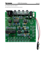
1
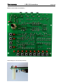
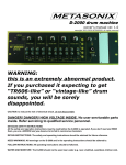
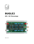
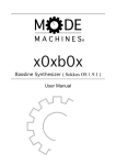
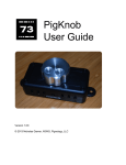
LDB-1 Kit Instructions Page 1 of 8 Important Information Congratulations and thank you for your purchase of the LDB-1 “Little Drummer Boy” Analog Drum Machine Kit! Before you start, please read the enclosed Electronic Kit Soldering Tutorial. It contains important and useful information even for experienced kit builders. If this is your first electronic kit, you sure picked a big one. It is not difficult to assemble, but there are a lot of parts. Take your time and be careful to put the right part in the right place. It is not easy to de-solder parts if you make a mistake. With some parts, it is important that the right lead goes in the right hole in the PCB (printed circuit board). For example electrolytic capacitors are polarized (they have a positive lead and a negative lead). Ceramic capacitors are not polarized, so it does not matter which of the two leads goes in which of the two holes. In these instructions the symbol (±) highlights parts that must be inserted with a particular orientation. The PCB is not marked with part values, but rather with reference designators (refdes). For example R1 refers to resistor number one and C1 refers to capacitor number one. Once the part value is identified, it is easy to find the refdes on the PCB. The parts in the kit are in two bags. One bag contains discreet components like resistors and capacitors, and the other bag contains electromechanical parts like jacks and switches. The discreet components are soldered first. Before you start, separate the parts by type. When you are ready to solder parts of a particular type, then separate them by value. In general, the order that the parts are soldered onto the PCB is shortest to tallest. In the instructions below, each part type is followed by the PCB outline for that part. Refer to the enclosed photograph of the completed kit for assistance with part identification. Top Side Parts The first group of parts are mounted on the “top” side of the PCB (the side with writing on it), and soldered on the “bottom” side. Only the pushbuttons, LEDs, and potentiometer are mounted on the bottom side. Chip Sockets (±) There are four 8-pin sockets and three 14-pin sockets. Sockets are marked with a small U-shaped notch that must line up with the outline on the PCB. Once the socket is soldered in place, the PCB outline will not be visible, so it is important that the sockets are oriented correctly in order to ensure that the chips are inserted correctly. Note that two of the 14-pin sockets go right next to each other to accommodate the 28-pin PIC18F26K22 chip. Diodes (±) There are 20 diodes. All of the diodes are the same value, so they have no refdes on the PCB, just a distinctive outline. The diodes are red and black glass. When inserted into the PCB, the black side of the diode must line up with the stripe on the part outline on the PCB. The diode leads need to be bent close to the body of the diode. Hold the diode body and press down on each lead right at the body to make a U shape. LDB-1 Kit Instructions Page 2 of 8 Resistors The value of a resistor is indicated by colored stripes on its body. In all cases the fifth stripe is brown (indicating 1% tolerance), so that stripe has been omitted from the chart below. The resistor leads need to be bent close to the body of the resistor. Hold the resistor body and press down on each lead right at the body to make a U shape. We recommend that you start with the 1K resistors because that is the most common value. Once they have been soldered onto the PCB, it will be much easier to find the other refdes values. Value 100R 220R 470R 560R 1K 2K2 3K3 4K7 10K 15K 22K 33K 47K 82K 100K 470K 1M 2M2 4M7 Marking (colored stripes) Quantity brown black black black 4 red red black black 1 yellow violet black black 1 green blue black black 1 brown black black brown 12 red red black brown 1 orange orange black brown 1 yellow violet black brown 1 brown black black red 5 brown green black red 1 red red black red 4 orange orange black red 1 yellow violet black red 5 gray red black red 1 brown black black orange 8 yellow violet black orange 2 brown black black yellow 9 red red black yellow 1 yellow violet black yellow 3 Refdes R54, R55, R56, R57 R58 R59 R10 R20, R27, R29, R32, R34, R38, R40, R43, R45, R50, R51, R60 R48 R49 R30 R7, R11, R35, R39, R44 R17 R8, R22, R52, R53 R23 R13, R15, R36, R41, R46 R9 R1, R2, R3, R4, R26, R31, R61, R62 R14, R16 R5, R6, R12, R18, R21, R24, R25, R28, R47 R33 R19, R37, R42 Ceramic Capacitors Ceramic capacitors are very small tan or blue blobs. Their value is marked on them with a three digit code. The marking is rather small, so you may have to use a magnifying glass to read them. We recommend that you start with the 0.01 uF capacitors because that is the most common value. Once they have been soldered onto the PCB, it will be much easier to find the other refdes values. Value 68 pF 470 pF 0.001 uF 0.0033 uF 0.0068 uF 0.022 uF 0.033 uF 0.047 uF 0.068 uF 0.1 uF 0.33 uF 0.47 uF 1 uF Marking 680 471 102 332 682 223 333 473 683 104 334 474 105 Quantity 1 3 1 4 2 2 4 2 2 11 1 1 1 Refdes C22 C12, C19, C23 C8 C9, C10, C16, C17 C28, C29 C32, C33 C26, C27, C30, C31 C11, C18 C34, C35 C1, C2, C3, C4, C5, C6, C7, C15, C21, C25, C38 C24 C13 C20 LDB-1 Kit Instructions Page 3 of 8 Electrolytic Capacitors (±) There are three electrolytic capacitors. Each one is a different value, which is clearly printed on the capacitor. Electrolytic capacitors are polarized, so which lead goes in which hole is important. The negative lead on the capacitor is the shorter one and it is marked with a gray stripe on its body. The positive lead is longer. The positive hole on the PCB has a square pad and is marked with a plus sign. Value 2.2 uF 4.7 uF 100 uF Quantity 1 1 1 Refdes C14 C36 C37 Transistors (±) There are three 2N3904 transistors. All three of the transistors are the same value, so they have no refdes on the PCB, just a distinctive outline. Note that the outline for U5 is similar to that of a transistor, but it is clearly labeled “U5” on the PCB. Make sure that the flat side of the transistor lines up with the flat side of the outline on the PCB. The transistors will not sit flush against the PCB. Do not force them down any further than they will go with a little pressure. Transistors are more heat sensitive than most of the parts in this kit, so take care not to let the soldering iron linger too long. If you are unsure, then solder one lead at a time and let the part fully cool off before soldering the next lead. Voltage Reference (±) The voltage reference chip (refdes U5) has the same basic shape as a transistor. There are several ways to tell them apart. First and foremost, U5 is marked with the part number TLE2426. Second, U5 is loose and the three transistors are taped to a piece of cardboard. And, finally, U5’s leads are straight and close together, while the transistor leads are bent and further apart. When you put them side by side, the differences become immediately apparent. When in doubt, read the marking on the part. Make sure that the flat side of U5 lines up with the flat side of the outline on the PCB. The leads on U5 are closer together than the holes in the PCB. Gently spread the leads out and press down on the part. It will not sit flush against the PCB. Do not force it down any further than it will go with a little gentle pressure. The voltage reference chip is more heat sensitive than most of the parts in this kit, so take care not to let the soldering iron linger too long. If you are unsure, then solder one lead at a time and let the part fully cool off before soldering the next lead. Programming Header This part is optional, and is used only for reprogramming the microcontroller brain of the LDB-1. If you install it, make sure it is seated flush against the PCB and points straight up. LDB-1 Kit Instructions Page 4 of 8 Power Switch The power switch can only be inserted one way. The switch actuator faces away from the PCB. Make sure it is seated flush against the PCB before soldering it. The switch will not stay in place by itself, so you may want to tape it in place while you solder it. Another tip is to solder only one of the pins, then check to make sure it is flush. If it is not flush, it is simple to reheat the one solder joint while pressing the switch into place. Once one pin is secure, the switch will stay in place while you solder the other pins. Power Jack The type M power jack can only be inserted one way. The opening of the jack faces away from the PCB. It will stay in place fairly well once inserted, however care must still be taken to ensure that it is seated flush against the PCB. 1/8 inch Jacks The four 1/8" jacks can only be inserted one way. The openings of the jacks face away from the PCB. Make sure they are seated flush against the PCB before soldering it. They snap into place and will stay put once inserted. MIDI / DINsync Jack The MIDI jack can only be inserted one way. The opening of the jack faces away from the PCB. Make sure it is seated flush against the PCB before soldering it. This jack will not stay in place by itself, so you may want to tape it in place while you solder it. Another tip is to solder only one of the pins, then check to make sure it is flush. If it is not flush, it is simple to reheat the one solder joint while pressing the jack into place. Once one pin is secure, the jack will stay in place while you solder the other pins. Battery Holder (±) The battery holder wires are first threaded down through the hole next to the battery pads, arched over, then soldered in place on top of the board. This keeps the battery wires from getting accidentally pulled out of the PCB. The black wire goes in the hole with the square pad, and the red wire goes in the hole with the round pad. After you have soldered the leads, gently pull the wires back through the hole so that they lie flat against the bottom of the PCB. That way, they won’t interfere with the overlay. Refer to the photo of the completed kit for reference. LDB-1 Kit Instructions Page 5 of 8 Bottom Side Components The pushbuttons, LEDs, and potentiometer are mounted on the “bottom” side of the PCB (the side without writing) and soldered on the “top” side. There are no part outlines on the bottom, but it is very easy to see where these parts go. They are all arranged around the edges of the PCB. When you go to solder the bottom side parts, you will see the leads sticking up through the part outline on the top side. Also, refer to the photo of the completed kit for reference. The included control panel overlay only fits if the pushbuttons, LEDs, and potentiometer are mounted on the bottom. If you choose to mount these parts on the top, you are free to do so, and the LDB-1 will still work fine. To tell the LDB-1 that you have mounted the controls top side, follow this one-time procedure: 1. 2. 3. 4. 5. Fully build and test the kit. Turn the power off. Hold down the BD button. Power on the unit. Wait for the mode LED to light up. Pushbuttons There are 12 pushbuttons. They snap into place and stay put while being soldered. Make sure they are seated flush against the PCB before soldering them. Note that they are rectangular, not square, so if the pins are not lining up, rotate it 90 degrees. LEDs (±) There are 12 LEDs. They are polarized, so the direction that they are inserted into the PCB is important. Make sure that the flat side of the LED lines up with the flat side of the shape on the PCB. You can also be sure that it is oriented correctly because the negative lead is the shorter one, and it goes in the hole indicated by the square pad. Make sure the LEDs are seated flush against the PCB before soldering them. If they are tilted, or are at different heights, then the overlay will not go into place correctly. The usual method of soldering leaded components is to insert the part into the PCB and bend the leads to keep it in place when you turn the PCB over to solder. Do not use that method, or the LEDs will not be flush. Potentiometer The potentiometer can only be inserted one way. It snaps in place and will stay there while you solder it. Be careful to press down evenly so you do not bend the pins. Make sure it is all the way in and seated flush against the PCB before soldering it. LDB-1 Kit Instructions Page 6 of 8 Chips There are six chips. Carefully insert each chip into its appropriate socket, making sure not to bend any of the pins. Note the direction of the chips before inserting them. The notch on the chip must line up with the notch on the socket. Refer to the photo of the completed kit for reference. The chip pins come from the factory a little bit splayed out, not pointing straight down. You may need to bend them inward a little before you insert them. Hold the body of the chip and rest all of the pins on one side against the table top and gently press down just a little bit. Then do the other side. If the pins do not line up well with the socket, repeat the straightening procedure. Value Quantity TL072 2 TL074 1 PIC12F508 1 PIC18F26K22 1 6N138N 1 Refdes U1, U3 U2 U4 U6 U7 Inspection At this stage, pause to inspect your work. Compare your PCB to the photo. Make sure that: You didn’t forget a part. The chips are oriented correctly. All of your solder joints are good. There are no solder bridges (blobs of solder covering two leads/pins). The leads are clipped off short – right above the solder. The bottom side parts are seated flush against the PCB. Test 1. Insert a new 9V battery in the battery clip and turn on the LDB-1. The first time you turn it on, there will be one to two second pause, then the mode LED should come on. If it does not come on, then something is wrong. Turn off the LDB-1, remove the battery and reinspect your work. Otherwise, go to the next step. 2. Insert a mono 1/8" (3.5mm) plug into the Audio output jack and plug the other end of the cable into your amplifier or mixer. 3. The LDB-1 starts in the “Play Drums” mode. Press the buttons along the bottom of the LDB-1 to play individual drum sounds. If you do not hear sounds, or if a particular drum does not sound, then something is wrong. Turn off and unplug the LDB-1 and reinspect your work. 4. If you have gotten this far, then you are good to go! Feet & Control Panel Overlay The overlay covers most of your soldering, so it is best to test the LDB-1 before putting it on. Turn the PCB bottom-up so that the buttons and LEDs are facing up. Place the overlay over the entire board so that the LEDs, buttons and potentiometer come through the holes. Insert the threads of a foot through one of the holes in a corner of the PCB and thread the nut onto the foot. It is easier to hold the nut and turn the foot. Repeat for the other three feet. Congratulations! You have successfully built an LDB-1 “Little Drummer Boy” Analog Drum Machine! Download the User Manual here: http://delptronics.com/documents/LDB1UserManual.pdf LDB-1 Kit Instructions Top / Component Side of Circuit Board Show before bottom side components have been soldered. Page 7 of 8 LDB-1 Kit Instructions Bottom / Controls Side of Circuit Board Detail showing foot, nut and overlay assembly. Page 8 of 8