1
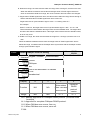
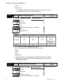
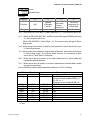
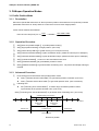
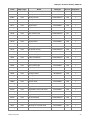
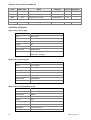
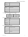
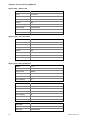
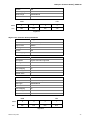
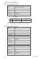
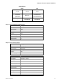
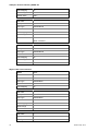
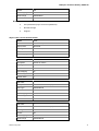
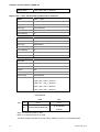
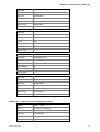
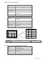
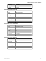
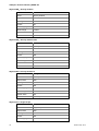
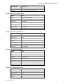
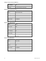
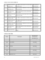
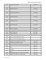
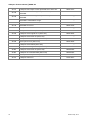
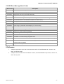
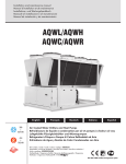
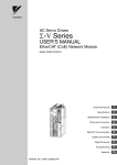
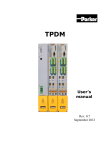
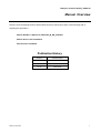
CANopen Technical Guide|
|ASDA-A2
Manual Overview
Please include the Manual Number and the Manual Version shown below when communicating with us
regarding this publication.
Manual Number: CANopen for ASDA-A2_M_EN_20120920
Manual Version: Second Edition
Release Date: 2012/09/20
Publication History
Revision Sep, 2012
Version
Release Date
V2.01
2012/09/20
V2.00
2012/07/27
V1.01
2009/11/30
1
CANopen Technical Guide|
| ASDA-A2
Contents
1. Communication Cable ........................................................................................... 5
1.1 Connectors - Pinout............................................................................................ 5
1.2 Baudrate Settings............................................................................................... 5
2. System Setup ......................................................................................................... 6
2.1 Scope of Function .............................................................................................. 6
2.1.1 Function supported by Delta ...................................................................... 6
2.1.2 Function not supported by Delta ................................................................ 6
2.2 Parameter Settings of CANopen Mode .............................................................. 7
2.2.1 Connect CANopen Host Controller ............................................................ 7
2.2.2 Parameters for CANopen Setup ................................................................ 7
3. CANopen Operation Modes .................................................................................. 14
3.1 Profile Position Mode ......................................................................................... 14
3.1.1 Description .............................................................................................. 14
3.1.2 Operation Procedure ............................................................................... 14
3.1.3 Advanced Procedure............................................................................... 14
3.1.4 Associated Object List............................................................................. 15
3.2 Interpolation Position Mode................................................................................ 16
3.2.1 Description ................................................................................................. 16
3.2.2 Operation Procedure.................................................................................. 16
3.2.3 Associated Object List................................................................................ 17
3.3 Homing Mode ..................................................................................................... 18
3.3.1 Description ................................................................................................. 18
3.3.2 Operation Procedure.................................................................................. 18
3.3.3 Associated Object List................................................................................ 18
3.4 Profile Velocity Mode.......................................................................................... 19
3.4.1 Description ................................................................................................. 19
3.4.2 Operation Procedure.................................................................................. 19
3.4.3 advanced ................................................................................................... 19
3.4.4 Associated Object List................................................................................ 19
3.5 Profile Torque Mode ........................................................................................... 20
3.5.1 Description ................................................................................................. 20
3.5.2 Operation Procedure.................................................................................. 20
3.5.3 Advanced ................................................................................................... 20
3.5.4 Associated Object List................................................................................ 21
2
Revision Sep, 2012
CANopen Technical Guide|
|ASDA-A2
4. Object Dictionary Entries ...................................................................................... 21
4.1 Specifications for Objects ................................................................................... 21
4.1.1 Object Type................................................................................................ 21
4.1.2 Data Type................................................................................................... 21
4.2 Overview of Object Group 1000h ....................................................................... 22
4.3 Overview of Object Group 6000h ....................................................................... 22
4.4 Details of Objects ............................................................................................... 24
5 Diagnostics and Troubleshooting ......................................................................... 62
5.1 CANopen Communication Fault Messages........................................................ 62
5.2 Error Code Table ................................................................................................ 64
5.3 SDO Error Message Abort Codes ...................................................................... 67
6 Reference ................................................................................................................ 67
Revision Sep, 2012
3
CANopen Technical Guide|
| ASDA-A2
(This page intentionally left blank)
4
Revision Sep, 2012
CANopen Technical Guide|
|ASDA-A2
1. Communication Cable
1.1 Connectors - Pinout
Pin Assignment (RJ-45) for CAN bus Wiring
Pin No.
Signal Name
Description
1
CAN_H
CAN_H bus line
2
CAN_L
CAN_L bus line
3
CAN_GND
Ground
4
---
Reserved
5
---
Reserved
6
---
Reserved
7
---
Reserved
8
---
Reserved
1.2 Baudrate Settings
Baudrate and Bus Length
Revision Sep, 2012
Baudrate
Bus Length
1Mbps
25m
750Kbps
50m
500Kbps(Default)
100m
250Kbps
250m
125Kbps
500m
5
CANopen Technical Guide|
|ASDA-A2
2. System Setup
2.1 Scope of Function
2.1.1 Function supported by Delta
CANopen protocol: NMT, SYNC, SDO, PDO, EMCY
SDO transfer for reading and writing parameters and communication settings.
PDO sends/receives along with time-trigger, event-trigger, sync cyclic and sync acyclic.
Node Guarding
Heartbeat
2.1.2 Function not supported by Delta
Time Stamp
6
Revision Sep, 2012
CANopen Technical Guide|
|ASDA-A2
2.2
Parameter Settings of CANopen Mode
2.2.1 Connect CANopen Host Controller
Users can follow the below instructions to connect CANopen Host Controller and servo drive A2.
①
Set parameter P1-01 to 0x0Bh or 0x0Ch for CANopen mode.
0x0Bh is used for simple CANopen mode and it does not support complete CANopen protocol;
0x0Ch is used for standard CANopen protocol and it is recommended to be connected to any
motion controller.
②
Set Parameter P3-00 to Node Id for range 01h~7Fh.
③
Set Parameter P3-01 to 0403h for Baudrate 1Mbps (0: 125Kbps; 1: 250Kbps; 2: 500 Kbps; 3:
750Kbps; 4:1Mbps).
④
Set Parameter P3-09 to 0x5055h for Synchronization.
2.2.2 Parameters for CANopen Setup
P1 - 01●
CTL
Address: 0102H,
0103H
Control Mode and Output Direction
Operation
Keypad / Software Communication
Interface:
Default: 0
Control
ALL
Mode:
Unit: pulse (P mode), r/min (S mode), N-m (T
mode)
Range: 00 ~ 110F
Data Size: 16-bit
Display
Hexadecimal
Format:
Related Section: 6.1,
Table 8.A
Settings:
A: Control mode settings
Pt
Pr
S
T
Single Mode
00
▲
01
▲
02
▲
03
▲
04
05
Multiple Mode
0E
▲
▲
▲
0F
▲
▲
▲
Revision Sep, 2012
Sz
Tz
▲
▲
Pt
06
07
08
09
0A
0B
0C
0D
▲
▲
▲
Pr
S
T
Sz
Dual Mode
▲
▲
▲
▲
▲
▲
▲
▲
CANopen Mode (Half)
CANopen Mode (Full)
▲
Tz
7
CANopen Technical Guide|
|ASDA-A2
Pt: Position control mode. The command is from external pulse or analog voltage (external
analog voltage will be available soon). Execution of the command selection is via DI
signal, PTAS.
Pr: Position control mode. The command is from internal signal. Execution of 64 positions is
via DI signals (POS0 ~ POS5). A variety of homing control is also provided.
S: Speed control mode. The command is from external signal or internal signal. Execution of
the command selection is via DI signals, SPD0 and SPD1.
T: Torque control mode. The command is from external signal or internal signal. Execution of
the command selection is via DI signals, TCM0 and TCM1.
Sz: Zero speed / internal speed command
Tz: Zero torque / internal torque command
Dual Mode: Control of the mode selection is via DI signals. For example, either Pt or S control
mode can be selected via DI signal, S-P (see Table 8.A).
Multiple Mode: Control of the mode selection is via DI signals. For example, either Pt or Pr or
S control mode can be selected via DI signals, S-P and Pt-Pr (see Table 8.A).
B: Torque output direction settings
Direction
0
1
Forward
Reverse
C: Discrete I/O Setting
1: When switching to different mode, digital inputs/outputs (P2-10 ~ P2-22) can be reset to be
the default value of the mode you switch to.
0: When switching to different mode, the setting value of digital inputs/outputs (P2-10 ~ P2-22)
will remain the same and will not be changed.
P3 - 00
ADR
Communication Address Setting
Operation
Keypad / Software
Interface:
Default: 0x7F
Control
ALL
Mode:
Unit: N/A
Range: 0x01 ~ 0x7F
Data Size: 16-bit
Display
Hexadecimal
Format:
Communication
Address: 0300H,
0301H
Related Section: 9.2
Settings:
This parameter is used to set the communication slave address in hexadecimal format.
This address is an absolute address which represents the servo drive on a RS-232/485 or
8
Revision Sep, 2012
CANopen Technical Guide|
|ASDA-A2
CANbus network.
Display
0
0
Y
X
Range
-
-
0~7
0~F
X: Axis number, the value must be within the range from 0 through F.
Y: Group number, the value must be within the range from 0 to through 7
If the AC servo drive is controlled by RS-232/485 communication, each drive (or device) must
be uniquely identified. One servo drive only can set one address. If the address is duplicated,
there will be a communication fault.
Please note:
1. This parameter does not provide broadcast function and does not respond insecurity.
2. When the address of host (external) controller is set to 0xFF, it is with auto-respond
function. Then, the servo drive will receive from and respond to host (external) controller
both no matter the address is matching or not. However, the parameter P3-00 cannot be
set to 0xFF.
P3 - 01
BRT
Address: 0302H,
0303H
Transmission Speed
Operation
Keypad / Software
Interface:
Default: 0x0203
Control
ALL
Mode:
Unit: bps
Range: 0x0000 ~ 0x0405
Data Size: 16-bit
Display
Hexadecimal
Format:
Communication
Related Section: 9.2
Settings:
This parameter is used to set the baud rate and data transmission speed of the
communications.
Display
0
Z
Y
X
COM Port
-
CAN
-
RS-232/485
Range
0
0~4
0
0~5
X: Baud rate setting
0: Baud rate 4800
1: Baud rate 9600
2: Baud rate 19200
3: Baud rate 38400
4: Baud rate 57600
Revision Sep, 2012
9
CANopen Technical Guide|
|ASDA-A2
5: Baud rate 115200
Y: Reserved. Must be set to be 0.
Z: Data transmission speed setting.
0: 125K bits / second
1: 250K bits / second
2: 500K bits / second (Default)
3: 750K bits / second
4: 1.0M bits / second
Please note:
1. When setting this parameter via CANopen communication, only the setting of Z (data
transmission speed setting) can be configured and other settings.
2. The communication transmission speed for USB can be set to 1.0M bits / second only and
cannot be changed.
P3 - 09
SYC
CANopen Synchronization Setting
Operation
Keypad / Software Communication
Interface:
Default: 0x5055
Control
CANopen
Mode:
Unit: N/A
Range: refer to the description of Settings
Data Size: 16-bit
Display
Hexadecimal
Format:
Address: 0312H,
0313H
Related Section: -
Settings:
This parameter is used to set the CANopen slave to be synchronized with the CANopen master
through synchronization signal. Although this parameter allows the users to execute manual
adjustment, if not necessary, we do not recommend users to change the default setting
manually.
Display
Function
Range
E
SYNC error
range
1~9
T
Target value
0~9
D
M
Dead zone
Clock correction
range
setting
0~F
1~F
M: Clock correction setting, the value must be within the range from 1 through F, and the unit is
usec.
When setting the CANopen slave to be synchronized with the CANopen master, the clock
of the servo drive must be corrected. This function is used to set the maximum correction
everytime.
10
Revision Sep, 2012
CANopen Technical Guide|
|ASDA-A2
D: Dead zone range, the value must be within the range from 0 through F, and the unit is usec.
When the difference between actual value and target value of SYNC signal reach time
does not exceed the dead zone range, the clock correction does not need to be changed.
T: Target value of SYNC signal reach time, the value must be within the range from 0 through 9,
and the standard value of SYNC signal reach time is 500 usec.
Target reach time of synchronization signal = 300 + 10 x setting value of T.
For example:
When T is set to 5, the target reach time of synchronization signal = 300 + 10 x 5 = 450
There should be a buffer between the target value and the standard value. The target value
should be less than the standard value. If the target value is above than the standard value,
an error may occur.
E: SYNC error range, the value must be within the range from 1 through 9, and the unit is 10
usec.
When the difference between actual value and target value of SYNC signal reach time is
below this range, it indicates that the CANopen slave synchronize with the CANopen master
through synchronization signal.
P3-10
Address: 0314H
0315H
Related Section: N/A
CANEN CANopen Protocol Setting
Operation
Keypad / Software Communication
Interface:
Default: 0x0000
Control
CANopen
Mode:
Unit: N/A
Range: refer to the description of Settings
Data Size: 16-bit
Display
Hexadecimal
Format:
Settings:
Display
Function
Range
U
N/A
N/A
Z
Y
N/A
Motor status
when CAN bus
N/A
X
CANopen
DS402
error occurs
protocol
version
0~1
0~1
X=0 : partially supportive for CANopen DS402 protocol. (for earlier Delta
products)
X=1: supportive for complete CANopen DS402 protocol.
Y=0: When CAN bus error occurs, free run.
Y=1: When CAN bus error occurs, servo off.
Z: N/A
Revision Sep, 2012
11
CANopen Technical Guide|
|ASDA-A2
U: N/A
Please note:
1. For ASDA-A2-M model, Y-bit is available, but X-bit is invalid.
2. For ASDA-A2-F model, X-bit is always be 1.
P3-11
Address: 0316H
0317H
Related Section: N/A
CANOP CANopen saving options
Operation
Keypad / Software Communication
Interface:
Default: 0x0000
Control
CANopen
Mode:
Unit: N/A
Range: refer to the description of Settings
Data Size: 16-bit
Display
Hexadecimal
Format:
Settings:
Display
U
Z
Y
Function
N/A
N/A
N/A
Range
N/A
N/A
0~F
X
Options of
saving
parameters in
EEPROM
0~1
X=0 : don’t save parameters in EEPROM
X=1: save parameters in EEPROM by PDO writing
Y: N/A
Z: N/A
U: N/A
Please note:
1. This parameter is only available for ASDA-A2 -M and -F models.
2. When X=1, continuously PDO writing parameters may shorten
EEPROM’s lifespan.
P3-12
QSTPO CANopen Quick Stop Settings
Operation
Keypad / Software Communication
Interface:
Default: 0x0000
Control
CANopen
Mode:
Unit: 0x0000 ~ 0x0111
Range: refer to the description of Settings
12
Address: 0318H
0319H
Related Section: N/A
Revision Sep, 2012
CANopen Technical Guide|
|ASDA-A2
Data Size: 16-bit
Display
Hexadecimal
Format:
Settings:
Display
U
Z
Function
N/A
Reload
CANopen
values
Range
N/A
0~1
Y
X
Optional Quick
OD-6040
Stop mode
supportive for
(in auto
Quick Stop
protection)
0~1
0~1
X=0:Only when OD-6040 Bit3(Enable Operation)=1, then execute servo on.
X=1:When all OD-6040 Bit0, Bit1, and Bit3 (meet CANopen DS402 protocols)
=1, then execute servo on.
When OD-6040 Bit2(Quick Stop)=1, then servo drive will go to Quick
Stop mode.
Y=0:When motor slows down to stop by auto protection, servo drive will not go
to Quick Stop mode.
Y=1:When motor slows down to stop by auto protection, servo drive will still go
to Quick Stop mode. To continue other actions, it’s necessary to give
servo drive “Fault Reset” command.
Z=0:When servo drive is power on or reset, parameters in below table will
reload the default settings.
Z=1:When servo drive is power on or reset, parameters in below table remain
the previous settings.
List of CANopen Object and parameters relative to P3-12 Z setting.
CANopen Object
Index
Default
605Bh
0
6065h
606Dh
606Eh
606Fh
6083h
6084h
6087h
6093h
3840000
100(0.1rpm)
0
100
200
200
200
1:1
Parameter
P1-32
P2-35
P1-47
P1-49
P1-38
P1-34
P1-34
P1-34
P1-44 / P1-45
Parameter
Default
P1-32.Y = 0,
Dynamic break enable(605Bh=-1)
P1-32.Y = 1,
Dynamic break disable(605Bh=0)
3840000
10(rpm)
0
100
200
200
200
128:10
U: N/A
Revision Sep, 2012
13
CANopen Technical Guide|
|ASDA-A2
3. CANopen Operation Modes
3.1 Profile Position Mode
3.1.1
Description
Servo drive (hereinafter referred to as “Drive”)receives position command from host (external) controller
(hereinafter referred to as “Host”) and then control servo motor to reach target position.
Pulse of User-defined Unit Definition:
Pulse of User Unit (PUU): No. of
3.1.2
OD - 6093 h Sub2
PUU
= 1280000 ×
OD - 6093 h Sub1
Rev
Operation Procedure
①
Set【Mode of operations:6060h】 to profile position mode(1).
②
③
④
Set【Target position:607Ah】to target position. (unit: PUU)
⑤
⑥
⑦
⑧
Set【Profile deceleration:6084h】to plan deceleration slope. (millisecond from 0rpm to 3000rpm)
Set【Profile velocity:6081h】to profile velocity. (unit: PUU per second)
Set【Profile acceleration:6083h】to plan acceleration slope. (millisecond from 0rpm to 3000rpm)
Set【Controlword:6040h】 to servo on drive and make motor work.
Query【Statusword:6064h】to get feedback position of motor.
Query【Statusword:6041h】to get drive status of following error、set-point acknowledge and target
reached.
3.1.3
Advanced Procedure
①
Host could get more information about profile position mode.
Query【Position demand value:6062h】to get internal position command. (unit: PUU)
Query【Position actual value*:6063h】to get actual position value. (unit: increments)
②
Following error
Set【Following error window:6065h】 to define range of tolerated position values
symmetrically to the position demand value. (unit: PUU)
Query【Following error actual value:60F4h】to get actual value of following error. (unit: PUU)
accepted following error tolerance
position
following error
window
following error
following error
window
no following error
following error
reference position
Reference position
14
Revision Sep, 2012
CANopen Technical Guide|
|ASDA-A2
③
Position window
Set【Position window:6067h】to define a symmetrical range of accepted positions relatively to
the target position. (unit: PUU)
Set【Position window time:6068h】to plan time of activation of target reached. (unit:
millisecond)
accepted position range
position
position window
position window
position reached
position not reached
position not reached
target position
Position reached
3.1.4 Associated Object List
Index
Name
Type
Attr.
6040h
Controlword
UNSIGNED16
RW
6041h
Statusword
UNSIGNED16
RO
6060h
Modes of operation
INTEGER8
RW
6061h
Modes of operation display
INTEGER8
RO
6062h
Position demand value [PUU]
INTEGER32
RO
6063h
Position actual value [increment]
INTEGER32
RO
6064h
Position actual value
INTEGER32
RO
6065h
Following error window
UNSIGNED32
RW
6067h
Position window
UNSIGNED32
RW
6068h
Position window time
UNSIGNED16
RW
607Ah
Target position
INTEGER32
RW
6081h
Profile velocity
UNSIGNED32
RW
6083h
Profile acceleration
UNSIGNED32
RW
6084h
Profile deceleration
UNSIGNED32
RW
6093h
Position factor
UNSIGNED32
RW
60F4h
Following error actual value
INTEGER32
RO
60FCh
Position demand value
INTEGER32
RO
(Please refer to the following “Details of Objects” section for more detailed descriptions)
Revision Sep, 2012
15
CANopen Technical Guide|
|ASDA-A2
3.2 Interpolation Position Mode
3.2.1 Description
The Host sends a broadcast SYNC frame (0x80) cyclically.
With each PDO, the Host sends the next reference position Xi, the difference△Xi and controlword
to the drive.
While the next SYNC receiving, the drive interpolates from Xi-1 to Xi.
There is no input data buffer, which will cause delay.
Extrapolation, Jitter Compensation
When SYNC object is delayed, the interpolator should generate with the last acceleration and
extrapolate predicted speed and position.
When the SYNC delays for 2*cycle, Drive should stop and send out an error message.
PDO Rx/Tx Mapping record
PDOs from Host to Drive
-
32 bit reference position [position increment]
-
16 bit symmetrical difference [increments]
△Xi = (Xi+1 – Xi-1)/2
-
(it is also the same as velocity)
16 bit control word.
PDO from Host to Drive (Every PDO contain 8 bytes field like below)
32 bit reference position
16 bit difference
16 bit controlword
3.2.2 Operation Procedure
①
Set【Mode of operations:6060h】to interpolation position mode(7).
②
P1-01 = 0x0B,
Set【Interpolation sub mode select:60C0h】to Interpolation mode.
If 60C0h is [0] or [-1], Host needs to send [60C1h Sub-3] and Drive will work more
precisely.
If 60C0h is [-2], Host does not need to send [60C1h Sub-3]. It could save calculating
time of Host and Drive could work also.
P1-01 = 0x0C,
Set【Interpolation sub mode select:60C0h】to Interpolation mode.
If 60C0h is [0], Host does not send [60C1h Sub-3]. It could save calculating time of host
and Drive could work also.
If 60C0h is [-1], Host need to send [60C1h Sub-3] and Drive will work more precisely.
③
P1-01 = 0x0B,
Set【Communication Cycle period:1006h】 to predict SYNC interval.
The unit of this object is microsecond.
It is recommended to set this value for a multiple of 1000 microsecond.
16
Revision Sep, 2012
CANopen Technical Guide|
|ASDA-A2
P1-01 = 0x0C,
Set【Interpolation time period:60C2h】 to predict SYNC receiving period.
60C2h Sub-1 for Interpolation time units. The range is from 1ms to 20ms.
60C2h Sub-2 for Interpolation time index. The value is always -3 meaning the
-3
interpolation time unit is 10 second.
④
Set PDO Communication & Mapping parameters via SDO.
Example:
Set 1400h Sub-1 for PDO RxCobId.
Set 1400h Sub-2 for PDO receive type [0x01] normally.
If using these steps, Host need to send SYNC and PDO data every Communication cycle.
⑤
Drive PDO Rx:
P1-01 = 0x0B,
60C1h Sub-1 for Pos Cmd (Low word)
60C1h Sub-2 for Pos Cmd (High word)
60C1h Sub-3 for Symmetrical Difference (optional)
6040h Sub-0 for ControlWord.
P1-01 = 0x0C,
60C1h Sub-1 for Pos Cmd (32-bit)
6040h Sub-0 for ControlWord.
⑥
⑦
Drive PDO Tx content could be set up to requirements of Host.
Receive NMT from Host to start or stop operation.
Note:
Because of difference of each oscillator, users must change parameter P3-09 to make drive to
automatically modify internal timer to match SYNC object period)
3.2.3 Associated Object List
Index
Name
Type
Attr.
6040h
Controlword
UNSIGNED16
RW
6041h
Statusword
UNSIGNED16
RO
6060h
Modes of operation
INTEGER8
RW
6061h
Modes of operation display
INTEGER8
RO
6093h
Position factor
UNSIGNED32
RW
60C0h
Interpolation sub mode select
INTEGER16
RW
60C1h
Interpolation data record
ARRAY
RW
(Please refer to the following “Details of Objects” section for more detailed descriptions)
Revision Sep, 2012
17
CANopen Technical Guide|
|ASDA-A2
3.3 Homing Mode
3.3.1 Description
This mode could help drive to seek the home position. The user can specify the speeds, acceleration
and the method of homing.
3.3.2 Operation Procedure
①
②
③
Set【Mode of operations:6060h】 to homing mode(6).
Set【Home offset:607Ch】
Set【Homing method:6098h】, method range is 1~35. (refer to OD-9098h definition
④
below)
Set【Homing speeds:6099h Sub-1】 to set speed during search for switch. (unit:
⑤
rpm)
Set【Homing speeds:6099h Sub-2】 to set speed during search for zero. (unit:
⑥
rpm)
Set【Homing acceleration:609Ah】 for homing acceleration. (unit: millisecond from
⑦
0rpm to 3000rpm)
Set【Controlword:6040h】 to servo on drive and make motor work.
⑧
⑨
Find Home Switch and do homing.
Query【Statusword:6041h】to get drive status.
3.3.3 Associated Object List
Index
Name
Type
Attr.
6040h
Controlword
UNSIGNED16
RW
6041h
Statusword
UNSIGNED16
RO
6060h
Modes of operation
INTEGER8
RW
6061h
Modes of operation display
INTEGER8
RO
607Ch
Home offset
INTEGER32
RW
6093h
Position factor
UNSIGNED32
RW
6098h
Homing method
INTEGER8
RW
6099h
Homing speeds
ARRAY
RW
609Ah
Homing acceleration
UNSIGNED32
RW
(Please refer to the following “Details of Objects” section for more detailed descriptions)
18
Revision Sep, 2012
CANopen Technical Guide|
|ASDA-A2
3.4 Profile Velocity Mode
3.4.1 Description
Drive could receive velocity commands and plan acceleration and deceleration.
3.4.2 Operation Procedure
①
②
Set【Mode of operations:6060h】 to profile velocity mode(3).
Set【Controlword:6040h】 to servo on drive and make motor work.
(After drive switch to servo-on, internal velocity command will be reset and OD-60FFh will be
cleared.)
③
④
⑤
Set【Profile acceleration:6083h】to plan acceleration slope. (millisecond from 0rpm to 3000rpm)
Set【Profile deceleration:6084h】to plan deceleration slope. (millisecond from 0rpm to 3000rpm)
Set【Target velocity:60FFh】. The unit of Target velocity is 0.1rpm.
(If drive already servo-on, the drive will work immediately while receiving velocity command.
OD-60FFh will be cleared to zero if OD-6060h[Mode] changed, Servo-Off or Quick-Stop is
activated.)
⑥
Query【Statusword:6041h】to get drive status.
3.4.3 advanced
①
Host could get information about velocity mode.
Query【Velocity demand value:606Bh】to get internal velocity command. (unit: 0.1rpm)
Query【Velocity actual value:606Ch】to get actual velocity value. (unit: 0.1rpm)
②
Host could set velocity monitor threshold.
Set【Velocity window:606Dh】to allocate velocity reached zone. (unit: 0.1rpm)
Set【Velocity widnow time:606Eh】to plan time of activation of velocity reached. (unit:
millisecond)
Set【Velocity threshold:606Fh】to allocate zero speed level. (unit: 0.1rpm)
3.4.4 Associated Object List
Index
Name
Type
Attr.
6040h
Controlword
UNSIGNED16
RW
6041h
Statusword
UNSIGNED16
RO
6060h
Modes of operation
INTEGER8
RW
6061h
Modes of operation display
INTEGER8
RO
606Bh
Velocity demand value
INTEGER32
RO
606Ch
Velocity actual value
INTEGER32
RO
Revision Sep, 2012
19
CANopen Technical Guide|
|ASDA-A2
Index
Name
Type
Attr.
606Dh
Velocity window
UNSIGNED16
RW
606Eh
Velocity window time
UNSIGNED16
RW
606Fh
Velocity threshold
UNSIGNED16
RW
60FFh
Target velocity
INTEGER32
RW
(Please refer to the following “Details of Objects” section for more detailed descriptions)
3.5 Profile Torque Mode
3.5.1 Description
Drive could receive torque command and plan profile torque slope.
3.5.2 Operation Procedure
①
②
Set【Mode of operations:6060h】 to profile torque mode(4).
Set【Controlword:6040h】 to servo on drive and make motor work.
(After drive switches to servo-on, internal torque command will be reset and OD-6071h will be
cleared. It means the drive is servo-on, then starts receiving torque command.)
③
④
Set【Torque slope:6087h】to plan torque slope time. (unit: millisecond from 0 to 100﹪rated torque)
Set【Target torque:6071h】to target torque. The unit is given per thousand of rated torque.
(OD-6071h will be cleared to zero if OD-6060h[Mode] changed, Servo-Off or Quick-Stop is
activated.)
3.5.3 Advanced
Host could get information about torque mode.
Query【Torque demand value:6074h】to get output value of the torque limit function. (unit: per
thousand of rated torque)
Query【Torque rated current:6075h】to get the rated current depending on the motor and drive
type. (unit: multiples of milliamp)
Query【Torque actual value:6077h】to get instantaneous torque in the drive motor. (unit: per
thousand of rated torque)
Query【Current actual value:6078h】to get instantaneous current in the drive motor. (unit: per
thousand of rated current)
20
Revision Sep, 2012
CANopen Technical Guide|
|ASDA-A2
3.5.4 Associated Object List
Index
Name
Type
Attr.
6040h
Controlword
UNSIGNED16
RW
6041h
Statusword
UNSIGNED16
RO
6060h
Modes of operation
INTEGER8
RW
6061h
Modes of operation display
INTEGER8
RO
6071h
Target torque
INTEGER16
RW
6074h
Torque demand value
INTEGER16
RO
6075h
Motor rated current
UNSIGNED32
RO
6077h
Torque actual value
INTEGER16
RO
6078h
Current actual value
INTEGER16
RO
6087h
Torque slope
UNSIGNED32
RW
(Please refer to the following “Details of Objects” section for more detailed descriptions)
4. Object Dictionary Entries
4.1 Specifications for Objects
4.1.1 Object Type
Object Name
VAR
ARRAY
Comments
A single value such as an UNSIGNED8, Boolean, float, INTEGER16 etc.
A multiple data field object where each data field is a sample variable of the
SAME basic data type e.g. array of UNSIGNED16 etc. Sub-index 0 is of
UNSIGNED8 and therefore not part of the ARRAY data
RECORD
A multiple data field object where the data fields may be any combination of
simple variables. Sub-index 0 is of UNSIGNED8 and therefore not part of the
RECORD data
4.1.2 Data Type
Please refer to CANopen Standard 301.
Revision Sep, 2012
21
CANopen Technical Guide|
|ASDA-A2
4.2 Overview of Object Group 1000h
Index
Object Type
1000h
VAR
1001h
VAR
1003h
ARRAY
1005h
Name
DataType
Access
device type
UNSIGNED32
RO
error register
UNSIGNED8
RO
pre-defined error field
UNSIGNED32
RW
VAR
COB-ID SYNC
UNSIGNED32
RW
1006h
VAR
communication cycle period
UNSIGNED32
RW
100Ch
VAR
guard time
UNSIGNED16
RW
100Dh
VAR
life time factor
UNSIGNED8
RW
1010h
ARRAY
store parameters
UNSIGNED32
RW
1011h
ARRAY
restore default parameters
UNSIGNED32
RW
1014h
VAR
COB-ID EMCY
UNSIGNED32
RO
1016h
ARRAY
Consumer heartbeat time
UNSIGNED32
RW
1017h
VAR
Producer heartbeat time
UNSIGNED16
RW
1018h
RECORD
Identity Object
UNSIGNED32
RO
1029h
ARRAY
Error Behavior
UNSIGNED8
RW
1200h
RECORD
1 Server SDO parameter
SDO Parameter
RO
1400h~03h
RECORD
Receive PDO parameter
UNSIGNED16/32
RW
1600h~03h
RECORD
Receive PDO mapping
UNSIGNED32
RW
1800h~03h
RECORD
Transmit PDO parameter
UNSIGNED16/32
RW
1A00h~03h
RECORD
Transmit PDO mapping
UNSIGNED32
RW
st
※ Only 1001h could be mapped to PDO
4.3 Overview of Object Group 6000h
22
Index
Object Type
603Fh
VAR
6040h
Name
DataType
Access
Mappable
Error Code
UNSIGNED16
RO
Y
VAR
Controlword
UNSIGNED16
RW
Y
6041h
VAR
Statusword
UNSIGNED16
RO
Y
605Bh
VAR
Shutdown option code
INTEGER16
RW
N
605Eh
VAR
Fault reaction option code
INTEGER16
RW
N
6060h
VAR
Modes of operation
INTEGER8
RW
Y
6061h
VAR
Modes of operation display
INTEGER8
RO
Y
6062h
VAR
Position demand value [PUU]
INTEGER32
RO
Y
6063h
VAR
Position actual value [increment]
INTEGER32
RO
Y
6064h
VAR
Position actual value
INTEGER32
RO
Y
6065h
VAR
Following error window
UNSIGNED32
RW
Y
6067h
VAR
Position windows
UNSIGNED32
RW
Y
6068h
VAR
Position window time
UNSIGNED16
RW
Y
Revision Sep, 2012
CANopen Technical Guide|
|ASDA-A2
Index
Object Type
606Bh
VAR
606Ch
DataType
Access
Mappable
Velocity demand value
INTEGER32
RO
Y
VAR
Velocity actual value
INTEGER32
RO
Y
606Dh
VAR
Velocity window
UNSIGNED16
RW
Y
606Eh
VAR
Velocity window time
UNSIGNED16
RW
Y
606Fh
VAR
Velocity threshold
UNSIGNED16
RW
Y
6071h
VAR
Target torque
INTEGER16
RW
Y
6074h
VAR
Torque demand value
INTEGER16
RO
Y
6075h
VAR
Motor rated current
UNSIGNED32
RO
Y
6076h
VAR
Motor rated torque
UNSIGNED32
RO
Y
6077h
VAR
Torque actual value
UNSIGNED16
RO
Y
6078h
VAR
Current actual value
INTEGER16
RO
Y
607Ah
VAR
Target position
INTEGER32
RW
Y
607Ch
VAR
Home Offset
INTEGER32
RW
Y
607Dh
ARRAY
Software position limit
INTEGER32
RW
Y
607Fh
VAR
Max profile velocity
UNSIGNED32
RW
Y
6080h
VAR
Max motor speed
UNSIGNED32
RW
Y
6081h
VAR
Profile velocity
UNSIGNED32
RW
Y
6083h
VAR
Profile acceleration
UNSIGNED32
RW
Y
6084h
VAR
Profile deceleration
UNSIGNED32
RW
Y
6085h
VAR
Quick stop deceleration
UNSIGNED32
RW
Y
6086h
VAR
Motion profile type
INTEGER16
RW
Y
6087h
VAR
Torque slope
UNSIGNED32
RW
Y
6093h
ARRAY
Position factor
UNSIGNED32
RW
Y
6098h
VAR
Homing method
INTEGER8
RW
Y
6099h
ARRAY
Homing speeds
UNSIGNED32
RW
Y
609Ah
VAR
Homing acceleration
UNSIGNED32
RW
Y
60B0h
VAR
Position offset
INTEGER32
RW
Y
60B1h
VAR
Velocity offset
INTEGER32
RW
Y
60B2h
VAR
Torque offset
INTEGER16
RW
Y
60C0h
VAR
Interpolation sub mode select
INTEGER16
RW
Y
60C1h
ARRAY
Interpolation data record
UNSIGNED16/32
RW
Y
60C2h
RECORD
Interpolation time period
SIGNED8
RW
Y
60C5h
VAR
Max acceleration
UNSIGNED32
RW
Y
60C6h
VAR
Max deceleration
UNSIGNED32
RW
Y
60F2h
VAR
Positioning option code
UNSIGNED16
RW
Y
60F4h
VAR
Following error actual value
INTEGER32
RO
Y
60FCh
VAR
Position demand value
INTEGER32
RO
Y
Revision Sep, 2012
Name
23
CANopen Technical Guide|
|ASDA-A2
Index
Object Type
Name
DataType
Access
Mappable
60FDh
VAR
Digital inputs
UNSIGNED32
RO
Y
60FFh
VAR
Target velocity
INTEGER32
RW
Y
6502h
VAR
Supported drive modes
UNSIGNED32
RO
Y
Parameter Mapping
INTEGER16/32
RW
Y
Delta parameter definition
2xxx
VAR
4.4 Details of Objects
Object 1000h: Device Type
INDEX
1000h
Name
device type
Object Code
VAR
Data Type
UNSIGNED32
Access
RO
PDO Mapping
No
Value Range
UNSIGNED32
Default Value
04020192 h : A2 Series
06020192h : M Series
Object 1001h: Error Register
INDEX
1001h
Name
error register
Object Code
VAR
Data Type
UNSIGNED8
Access
RO
PDO Mapping
Yes
Value Range
UNSIGNED8
Default Value
0
Object 1003h: Pre-defined Error Field
24
INDEX
1003h
Name
pre-defined error field
Object Code
ARRAY
Data Type
UNSIGNED32
Access
RW
PDO Mapping
No
Sub-Index
0
Description
number of errors
Data Type
UNSIGNED8
Revision Sep, 2012
CANopen Technical Guide|
|ASDA-A2
Access
RW
PDO Mapping
No
Value Range
0~5
Default Value
0
Sub-Index
1~5
Description
standard error field
Data Type
UNSIGNED32
Access
RO
PDO Mapping
No
Value Range
UNSIGNED32
Default Value
0
Example: if AL.011 occurs, the errorcode will store in Array of 1003h
Byte:
MSB
Additional
Information(UINT16)
LSB
Error code(UINT16)
0x0011 (AL.011)
0x7305
Object 1005h: COB-ID SYNC message
INDEX
1005h
Name
COB-ID SYNC message
Object Code
VAR
Data Type
UNSIGNED32
Access
RW
PDO Mapping
No
Value Range
UNSIGNED32
Default Value
80 h
Object 1006h: Communication Cycle Period
INDEX
1006h
Name
communication cycle period
Object Code
VAR
Data Type
UNSIGNED32
Access
RW
PDO Mapping
No
Value Range
UNSIGNED32
Default Value
0
Comment
Unit: microsecond
Revision Sep, 2012
25
CANopen Technical Guide|
|ASDA-A2
Object 100Ch: Guard Time
INDEX
100Ch
Name
guard time
Object Code
VAR
Data Type
UNSIGNED16
Access
RW
PDO Mapping
No
Value Range
UNSIGNED16
Default Value
0
Comment
Unit: millisecond
Object 100Dh: Life Time Factor
INDEX
100Dh
Name
life time factor
Object Code
VAR
Data Type
UNSIGNED8
Access
RW
PDO Mapping
No
Value Range
UNSIGNED8
Default Value
0
Object 1010h: Store parameters
26
INDEX
1010h
Name
store parameters
Object Code
ARRAY
Data Type
UNSIGNED32
Access
RW
PDO Mapping
No
Sub-Index
0
Description
largest sub-index supported
Data Type
UNSIGNED8
Access
RO
PDO Mapping
No
Value Range
1
Default Value
1
Sub-Index
1
Description
save all default parameters
Data Type
UNSIGNED32
Revision Sep, 2012
CANopen Technical Guide|
|ASDA-A2
Access
RW
PDO Mapping
No
Value Range
UNSIGNED32
Default Value
1
MSB
LSB
ASCII
e
v
a
s
hex
65h
76h
61h
73h
Signature
Object 1011h: Restore default parameters
INDEX
1011h
Name
restore default parameters
Object Code
ARRAY
Data Type
UNSIGNED32
Access
RW
PDO Mapping
No
Sub-Index
0
Description
largest sub-index supported
Data Type
UNSIGNED8
Access
RO
PDO Mapping
No
Value Range
1
Default Value
1
Sub-Index
1
Description
restore all default parameters
Data Type
UNSIGNED32
Access
RW
PDO Mapping
No
Value Range
UNSIGNED32
Default Value
1
MSB
ASCII
hex
LSB
d
a
o
l
64h
61h
6Fh
6Ch
Signature
Revision Sep, 2012
27
CANopen Technical Guide|
|ASDA-A2
Object 1014h: COB-ID Emergency Object
INDEX
1014h
Name
COB-ID Emergency message
Object Code
VAR
Data Type
UNSIGNED32
Access
RO
PDO Mapping
No
Value Range
UNSIGNED32
Default Value
80 h + Node-ID
UNSIGNED32
MSB
bits
LSB
31
30~11
10~0
0/1
00000000000000000000
11-bit Identifier COB-ID
Bit31 is 0 means that EMCY is valid (Drive will send EMCY)
Bit31 is 1 means that EMCY is not valid (Drive will not send EMCY)
Object 1016h: Consumer Heartbeat Time
28
INDEX
1016h
Name
Consumer Heartbeat Time
Object Code
ARRAY
Data Type
UNSIGNED32
Access
RW
PDO Mapping
No
Sub-Index
0
Description
number entries
Data Type
UNSIGNED8
Access
RO
PDO Mapping
No
Value Range
1
Default Value
1
Sub-Index
1
Description
Consumer Heartbeat Time
Data Type
UNSIGNED32
Access
RW
PDO Mapping
No
Value Range
UNSIGNED32
Default Value
0
Revision Sep, 2012
CANopen Technical Guide|
|ASDA-A2
UNSIGNED32
MSB
LSB
31~24
23~16
Reserved
Node-ID
(value:00h)
15~0
Heartbeat time
(Unit:millisecond)
-
UNSIGNED8
UNSIGNED8
Object 1017h: Producer Heartbeat Time
INDEX
1017h
Name
Producer Heartbeat Time
Object Code
VAR
Data Type
UNSIGNED16
Access
RW
PDO Mapping
No
Value Range
UNSIGNED16
Default Value
0
Object 1018h: Identity Object
INDEX
1018h
Name
Identity Object
Object Code
RECORD
Data Type
Identity
Access
RO
PDO Mapping
No
Sub-Index
0
Description
number of entries
Data Type
UNSIGNED8
Access
RO
PDO Mapping
No
Value Range
3
Default Value
3
Sub-Index
1
Description
Vendor ID
Data Type
UNSIGNED32
Access
RO
Revision Sep, 2012
29
CANopen Technical Guide|
|ASDA-A2
PDO Mapping
No
Value Range
UNSIGNED32
Default Value
1DD h
Sub-Index
2
Description
Product code
Data Type
UNSIGNED32
Access
RO
PDO Mapping
No
Value Range
UNSIGNED32
Default Value
6000 h : A2 Series
6030h : M Series
Sub-Index
3
Description
Revision number
Data Type
UNSIGNED32
Access
RO
PDO Mapping
No
Value Range
UNSIGNED32
Default Value
N/A
Object 1029h: Error Behavior
30
INDEX
1029h
Name
Error Behavior
Object Code
ARRAY
Data Type
UNSIGNED8
Access
RW
PDO Mapping
No
Sub-Index
0
Description
No. of Error Classes
Data Type
UNSIGNED8
Access
RO
PDO Mapping
No
Value Range
1
Default Value
1
Sub-Index
1
Description
Communication Error
Data Type
UNSIGNED8
Revision Sep, 2012
CANopen Technical Guide|
|ASDA-A2
Access
RW
PDO Mapping
No
Value Range
UNSIGNED8
Default Value
0
Note:
0
Pre-operational (only if current is operational)
1
No state change
2
stopped
Object 1200h: Server SDO Parameter
INDEX
1200h
Name
Server PDO parameter
Object Code
RECORD
Data Type
SDO Parameter
Access
RO
PDO Mapping
No
Sub-Index
0
Description
number of entries
Data Type
UNSIGNED8
Access
RO
PDO Mapping
No
Value Range
2
Default Value
2
Sub-Index
1
Description
COB-ID Client->Server (rx)
Data Type
UNSIGNED32
Access
RO
PDO Mapping
No
Value Range
UNSIGNED32
Default Value
Index 1200 h: 600 h + Node-ID
Sub-Index
2
Description
COB-ID Server->Client (tx)
Data Type
UNSIGNED32
Access
RO
PDO Mapping
No
Value Range
UNSIGNED32
Revision Sep, 2012
31
CANopen Technical Guide|
|ASDA-A2
Default Value
Index 1200 h: 580 h + Node-ID
Object 1400h ~ 1403h: Receive PDO Communication Parameter
INDEX
1400h ~ 1403h
Name
Receive PDO parameter
Object Code
RECORD
Data Type
PDO CommPar
Access
RW
PDO Mapping
No
Sub-Index
0
Description
largest sub-index supported
Data Type
UNSIGNED8
Access
RO
PDO Mapping
No
Value Range
5
Default Value
5
Sub-Index
1
Description
COB-ID used by PDO
Data Type
UNSIGNED32
Access
RW
PDO Mapping
No
Value Range
UNSIGNED32
Default Value
Default Node-ID: 0
Index 1400 h: 200 h + Node-ID
Index 1401 h: 300 h + Node-ID
Index 1402 h: 400 h + Node-ID
Index 1403 h: 500 h + Node-ID
UNSIGNED32
MSB
bits
31
30~11
0/1
00000000000000000000
LSB
10~0
11-bit Identifier
COB-ID
Bit31 is 0 means that PDO is valid
Bit31 is 1 means that PDO is not valid
The PDO valid/not valid allows to select which PDOs are used in the operational state.
32
Revision Sep, 2012
CANopen Technical Guide|
|ASDA-A2
Sub-Index
2
Description
Reception type
Data Type
UNSIGNED8
Access
RW
PDO Mapping
No
Value Range
UNSIGNED8
Default Value
0
Sub-Index
3
Description
inhibit time (not used for RPOD)
Data Type
UNSIGNED16
Access
RW
PDO Mapping
No
Value Range
UNSIGNED16
Default Value
0
Sub-Index
4
Description
compatibility entry
Data Type
UNSIGNED8
Access
RW
PDO Mapping
No
Value Range
UNSIGNED8
Default Value
0
Sub-Index
5
Description
event timer (not used for RPDO)
Data Type
UNSIGNED16
Access
RW
PDO Mapping
No
Value Range
UNSIGNED16
Default Value
0
Object 1600h ~ 1603h: Receive PDO Mapping Parameter
INDEX
1600h ~ 1603h
Name
Receive PDO mapping
Object Code
RECORD
Data Type
PDO Mapping
Access
RW
PDO Mapping
No
Revision Sep, 2012
33
CANopen Technical Guide|
|ASDA-A2
Sub-Index
0
Description
Number of mapped application objects in PDO
Data Type
UNSIGNED8
Access
RW
PDO Mapping
No
Value Range
0: deactivated
1~8: activated
Default Value
0
Sub-Index
1~8
Description
PDO mapping for the nth application object to
be mapped
Data Type
UNSIGNED32
Access
RW
PDO Mapping
No
Value Range
UNSIGNED32
Default Value
0
Object Dictionary
Application
aaaa
xx
Object 1
PDO Mapping
0
3
1
bbbb
yy
08h
2
cccc
zz
20h
3
aaaa
xx
10h
Application
Object 2
bbbb
yy
Application
Object 2
cccc
zz
Application
Object 3
Application Object 3
Application Object 1
Object 1800h ~ 1803h: Transmit PDO Communication Parameter
34
INDEX
1800h ~ 1803h
Name
transmit PDO parameter
Object Code
RECORD
Data Type
PDO CommPar
Access
RW
PDO Mapping
No
Revision Sep, 2012
CANopen Technical Guide|
|ASDA-A2
Sub-Index
0
Description
largest sub-index supported
Data Type
UNSIGNED8
Access
RO
PDO Mapping
No
Value Range
5
Default Value
5
Sub-Index
1
Description
COB-ID used by PDO
Data Type
UNSIGNED32
Access
RW
PDO Mapping
No
Value Range
UNSIGNED32
Default Value
Default Node-ID: 0
Index 1800 h: 180 h + Node-ID
Index 1801 h: 280 h + Node-ID
Index 1802 h: 380 h + Node-ID
Index 1803 h: 480 h + Node-ID
UNSIGNED32
MSB
bits
LSB
31
30~11
10~0
0/1
00000000000000000000
11-bit Identifier COB-ID
Bit31 is 0 means that PDO is valid
Bit31 is 1 means that PDO is not valid
The PDO valid/not valid allows to select which PDOs are used in the operational state.
Sub-Index
2
Description
Transmission type
Data Type
UNSIGNED8
Access
RW
PDO Mapping
No
Value Range
UNSIGNED8
Default Value
0
Sub-Index
3
Description
inhibit time
Data Type
UNSIGNED16
Revision Sep, 2012
35
CANopen Technical Guide|
|ASDA-A2
Access
RW
PDO Mapping
No
Value Range
UNSIGNED16
Default Value
0
Sub-Index
4
Description
reserved
Data Type
UNSIGNED8
Access
RW
PDO Mapping
No
Value Range
UNSIGNED8
Default Value
0
Sub-Index
5
Description
event timer
Data Type
UNSIGNED16
Access
RW
PDO Mapping
No
Value Range
0: not used
UNSIGNED16
Default Value
0
Object 1A00h ~ 1A03h: Transmit PDO Mapping Parameter
INDEX
1A00h ~ 1A03h
Name
Transmit PDO mapping
Object Code
RECORD
Data Type
PDO Mapping
Access
RW
PDO Mapping
No
Sub-Index
0
Description
Number of mapped application objects in PDO
Data Type
UNSIGNED8
Access
RW
PDO Mapping
No
Value Range
0: deactivated
1~8: activated
36
Default Value
0
Sub-Index
1~8
Revision Sep, 2012
CANopen Technical Guide|
|ASDA-A2
Description
PDO mapping for the nth application object to
be mapped
Data Type
UNSIGNED32
Access
RW
PDO Mapping
No
Value Range
UNSIGNED32
Default Value
0
Object 603Fh: Error code (errorcode of CANopen defined)
INDEX
603Fh
Name
Error code
Object Code
VAR
Data Type
UNSIGNED16
Access
RO
PDO Mapping
Yes
Value Range
UNSIGNED16
Default Value
0
Object 6040h: Controlword
INDEX
6040h
Name
Controlword
Object Code
VAR
Data Type
UNSIGNED16
Access
RW
PDO Mapping
Yes
Value Range
UNSIGNED16
Default Value
P1-01 = 0x0B, Default is 0x0000
P1-01 = 0x0C, Default is 0x0004
Revision Sep, 2012
37
CANopen Technical Guide|
|ASDA-A2
ControlWord
(6040h)
State Machine
StatusWord
(6041h)
State machine in system context
Bit Definition
15~9
8
N/A
7
Halt
6~4
Fault reset
3
Operation mode specific
Enable
operation
2
Quick
Stop
(B-contact)
1
0
Enable
Switch
voltage
on
Note:
If P1-01 = 0x0B, user could set 6040h to 0x000F for ServoOn immediately.
If P1-01 = 0x0C, user need to set 6040h to 0x0006->0x0007->0x000F for Servo On step by step.
Operation mode
Bit
PP
HM
New set-point
Homing operation start
(positive trigger)
(positive trigger)
5
Change set immediately
6
Absolute(0) / relative(1)
4
IP
PV
PT
N/A
N/A
N/A
N/A
N/A
N/A
N/A
N/A
N/A
N/A
N/A
Abbreviation:
38
PP
Profile Position Mode
HM
Homing Mode
IP
Interpolated Position Mode
PV
Profile Velocity Mode
PT
Profile Torque Mode
Revision Sep, 2012
CANopen Technical Guide|
|ASDA-A2
Velocity
v2
v1
t0
t1
t2
t3
time
Single set-point
Velocity
v2
v1
t1
t0
t2
time
Change settings immediately
Object 6041h: Statusword
INDEX
6041h
Name
Statusword
Object Code
VAR
Data Type
UNSIGNED16
Access
RO
PDO Mapping
Yes
Value Range
UNSIGNED16
Default Value
0
Data Description
15
14
13
12
11
10
9
8
7
6
5
MSB
4
3
2
1
0
LSB
Bit Definition
0
Ready to swtich on
1
Switch on
2
Operation enabled (status of servo on)
3
Fault (Drive will servo off)
4
Voltage enabled
5
Quick stop
6
Switch on disabled
7
Warning (drive still servo on)
8
N/A
9
Remote
10
Target reached
11
Internal limit active (Not supported)
Revision Sep, 2012
39
CANopen Technical Guide|
|ASDA-A2
PP
HM
IP
PV
PT
Homing attained
IP mode active
Zero Speed
N/A
Set-point
12
acknowledge
13
Following error
Homing error
N/A
N/A
N/A
14
N/A
N/A
SYNC OK
N/A
N/A
15
N/A
N/A
N/A
N/A
N/A
Note:
Set-point acknowledge: Trajectory generator has assumed the positioning values
Homing attained: Homing mode carried out successfully
IP mode active: interpolated position mode active – mode is running in IP mode
SYNC OK: SYNC frame is reached before path generator starts
Object 605Bh: Shutdown option code
INDEX
605Bh
Name
Shutdown option code
Object Code
VAR
Data Type
INTEGER16
Access
RW
PDO Mapping
Yes
Value Range
INTEGER16
Default Value
0
Comment
0:Disable drive function
-1:Dynamic break enable
Object 605Eh: Fault reaction option code
INDEX
605Eh
Name
Fault reaction option code
Object Code
VAR
Data Type
INTEGER16
Access
RW
PDO Mapping
Yes
Value Range
INTEGER16
Default Value
2
Comment
0:Disable drive, motor is free to rotate
1:slow down on slow down ramp
2:slow down on quick stop ramp
40
Revision Sep, 2012
CANopen Technical Guide|
|ASDA-A2
Object 6060h: Modes of operation
INDEX
6060h
Name
Modes of operation
Object Code
VAR
Data Type
INTEGER8
Access
RW
PDO Mapping
Yes
Value Range
INTEGER8
Default Value
0
Comment
0:Reserved
1:Profile position mode
3:Profile velocity mode
4:Profile torque mode
6:Homing mode
7:Interpolated position mode
Object 6061h: Modes of operation display
INDEX
6061h
Name
Modes of operation display
Object Code
VAR
Data Type
INTEGER8
Access
RW
PDO Mapping
Yes
Value Range
INTEGER8
Default Value
0
Object 6062h: Position demand value
INDEX
6062h
Name
Position demand value
Object Code
VAR
Data Type
INTEGER32
Access
RO
PDO Mapping
Yes
Value Range
INTEGER32
Default Value
0
Comment
Position command calculated by Interpolation
theory
Unit: PUU
Revision Sep, 2012
41
CANopen Technical Guide|
|ASDA-A2
Object 6063h: Position demand value
INDEX
6063h
Name
Position actual value*
Object Code
VAR
Data Type
INTEGER32
Access
RO
PDO Mapping
Yes
Value Range
INTEGER32
Default Value
0
Comment
Unit: increments
Object 6064h: Position actual value
INDEX
6064h
Name
Position actual value
Object Code
VAR
Data Type
INTEGER32
Access
RO
PDO Mapping
Yes
Value Range
INTEGER32
Default Value
0
Comment
Unit: PUU
Object 6065h: Following error window
INDEX
6065h
Name
Following error window
Object Code
VAR
Data Type
UNSIGNED32
Access
RW
PDO Mapping
Yes
Value Range
UNSIGNED32
Default Value
3840000
Comment
Unit: PUU
Object 6067h: Position window
42
INDEX
6067h
Name
Position window
Object Code
VAR
Data Type
UNSIGNED32
Access
RW
PDO Mapping
Yes
Revision Sep, 2012
CANopen Technical Guide|
|ASDA-A2
Value Range
UNSIGNED32
Default Value
100
Comment
Unit: PUU
Object 6068h: Position window time
INDEX
6068h
Name
Position window time
Object Code
VAR
Data Type
UNSIGNED16
Access
RW
PDO Mapping
Yes
Value Range
UNSIGNED16
Default Value
0
Comment
Unit: millisecond
Object 606Bh: Velocity demand value
INDEX
606Bh
Name
Velocity demand value
Object Code
VAR
Data Type
INTEGER32
Access
RO
PDO Mapping
Yes
Value Range
INTEGER32
Comment
Unit: 0.1rpm
Object 606Ch: Velocity actual value
INDEX
606Ch
Name
Velocity actual value
Object Code
VAR
Data Type
INTEGER32
Access
RO
PDO Mapping
Yes
Value Range
INTEGER32
Comment
Unit: 0.1rpm
Revision Sep, 2012
43
CANopen Technical Guide|
|ASDA-A2
Object 606Dh: Velocity window
INDEX
606Dh
Name
Velocity window
Object Code
VAR
Data Type
INTEGER16
Access
RO
PDO Mapping
Yes
Value Range
0~3000
Default Value
100
Comment
Unit: 0.1rpm
Object 606Eh: Velocity window time
INDEX
606Eh
Name
Velocity window time
Object Code
VAR
Data Type
UNSIGNED16
Access
RW
PDO Mapping
Yes
Value Range
UNSIGNED16
Default Value
0
Comment
Unit: millisecond
Object 606Fh: Velocity threshold
INDEX
606Fh
Name
Velocity threshold
Object Code
VAR
Data Type
UNSIGNED16
Access
RW
PDO Mapping
Yes
Value Range
0~2000
Default Value
100
Comment
Unit: 0.1rpm
Object 6071h: Target torque
44
INDEX
6071h
Name
Target torque
Object Code
VAR
Data Type
INTEGER16
Access
RW
PDO Mapping
Yes
Revision Sep, 2012
CANopen Technical Guide|
|ASDA-A2
Value Range
-3000~3000
Default Value
0
Comment
Unit: per thousand of rated torque
Object 6074h: Torque demand value
INDEX
6074h
Name
Torque demand value
Object Code
VAR
Data Type
INTEGER16
Access
RO
PDO Mapping
Yes
Value Range
INTEGER16
Comment
Unit: per thousand of rated torque
Object 6075h: Motor rated current
INDEX
6075h
Name
Motor rated current
Object Code
VAR
Data Type
UNSIGNED32
Access
RO
PDO Mapping
Yes
Value Range
UNSIGNED32
Comment
Unit: milliamp
Object 6076h: Motor rated toruqe
INDEX
6076h
Name
Motor rated torque
Object Code
VAR
Data Type
UNSIGNED32
Access
RO
PDO Mapping
Yes
Value Range
UNSIGNED32
Comment
Unit: per thousand of rate torque
Object 6077h: Torque actual value
INDEX
6077h
Name
Torque actual value
Object Code
VAR
Data Type
INTEGER16
Access
RO
Revision Sep, 2012
45
CANopen Technical Guide|
|ASDA-A2
PDO Mapping
Yes
Value Range
INTEGER16
Comment
Unit: per thousand of rate torque
Object 6078h: Current actual value
INDEX
6078h
Name
Current actual value
Object Code
VAR
Data Type
INTEGER16
Access
RO
PDO Mapping
Yes
Value Range
INTEGER16
Comment
Unit: per thousand of rated current
Object 607Ah: Target position
INDEX
607Ah
Name
Target position
Object Code
VAR
Data Type
INTEGER32
Access
RW
PDO Mapping
Yes
Value Range
INTEGER32
Default Value
0
Comment
For Profile position mode 6060h=1
Unit: PUU
Object 607Ch: Home offset
46
INDEX
607Ch
Name
Home offset
Object Code
VAR
Data Type
INTEGER32
Access
RW
PDO Mapping
Yes
Value Range
INTEGER32
Default Value
0
Comment
Unit : PUU
Revision Sep, 2012
CANopen Technical Guide|
|ASDA-A2
Home
Position
home offset
Zero
Position
Home offset
Object 607Fh: Max profile velocity
INDEX
607Fh
Name
Max profile velocity
Object Code
VAR
Data Type
UNSIGNED32
Access
RW
PDO Mapping
Yes
Value Range
UNSIGNED32
Default Value
P1-55(rpm) * 10
Comment
Unit:0.1rpm
Object 6080h: Max motor speed
INDEX
6080h
Name
Max motor speed
Object Code
VAR
Data Type
UNSIGNED32
Access
RW
PDO Mapping
Yes
Value Range
UNSIGNED32
Default Value
P1-55(rpm)
Comment
Unit:rpm
Object 6081h: Profile velocity
INDEX
6081h
Name
Profile Velocity
Object Code
VAR
Data Type
UNSIGNED32
Access
RW
PDO Mapping
Yes
Value Range
UNSIGNED32
Default Value
10000
Comment
For Profile position mode 6060h=1
Unit: PUU per second
Revision Sep, 2012
47
CANopen Technical Guide|
|ASDA-A2
Object 6083h: Profile acceleration
INDEX
6083h
Name
Profile acceleration
Object Code
VAR
Data Type
UNSIGNED32
Access
RW
PDO Mapping
Yes
Value Range
1~UNSIGNED32
Default Value
200
Comment
For Profile position mode 6060h=1
Unit: millisecond (time from 0rpm to 3000rpm)
Object 6084h: Profile deceleration
INDEX
6084h
Name
Profile deceleration
Object Code
VAR
Data Type
UNSIGNED32
Access
RW
PDO Mapping
Yes
Value Range
1~UNSIGNED32
Default Value
200
Comment
For Profile position mode 6060h=1
Unit: millisecond (time from 0rpm to 3000rpm)
Object 6085h: Quick stop deceleration
INDEX
6085h
Name
Quick stop acceleration
Object Code
VAR
Data Type
UNSIGNED32
Access
RW
PDO Mapping
Yes
Value Range
UNSIGNED32
Default Value
0
Comment
Unit: millisecond (time from 0rpm to 3000rpm)
Object 6086h: Motion profile type
48
INDEX
6086h
Name
Motion profile type
Object Code
VAR
Data Type
INTEGER16
Revision Sep, 2012
CANopen Technical Guide|
|ASDA-A2
Access
RW
PDO Mapping
Yes
Value Range
INTEGER16
Default Value
0
Object 6087h: Torque slope
INDEX
6087h
Name
Torque slope
Object Code
VAR
Data Type
UNSIGNED32
Access
RW
PDO Mapping
Yes
Value Range
UNSIGNED32
Default Value
0
Comment
Unit: millisecond (time from 0 to 100% rated
torque)
Object 6093h: Position factor
INDEX
6093h
Name
Position factor
Object Code
ARRAY
Data Type
UNSIGNED32
Access
RW
PDO Mapping
Yes
Comment
Position factor =
Numerator / Feed_constant
Sub-Index
0
Description
Number of entries
Data Type
UNSIGNED8
Access
RO
PDO Mapping
No
Value Range
2
Default Value
2
Sub-Index
1
Description
Numerator
Data Type
UNSIGNED32
Access
RW
PDO Mapping
Yes
Revision Sep, 2012
49
CANopen Technical Guide|
|ASDA-A2
Default Value
1
Comment
Same as P1-44
Sub-Index
2
Description
Feed_constant
Data Type
UNSIGNED32
Access
RW
PDO Mapping
Yes
Default Value
1
Comment
Same as P1-45
Object 6098h: Homing method
INDEX
6098h
Name
Homing method
Object Code
VAR
Data Type
INTEGER8
Access
RW
PDO Mapping
Yes
Value Range
0~35
Default Value
0
1
Index Pulse
Negtive Limit Switch
Method1:Homing on the negative limit switch and index pulse
2
Index Pulse
Positive Limit Switch
Method2:Homing on the positive limit switch and index pulse
50
Revision Sep, 2012
CANopen Technical Guide|
|ASDA-A2
3
3
4
4
Index Pulse
Home Switch
Method 3 and 4:Homing on the positive home switch and index pulse
5
5
6
6
Index Pulse
Home Switch
Method 5 and 6:Homing on the negative home switch and index pulse
Revision Sep, 2012
51
CANopen Technical Guide|
|ASDA-A2
8
7
10
9
7
10
8
7
9
9
8
10
Index Pulse
Home Switch
Positive Limit Switch
14
12
11
13
14
11
13
12
13
14
11
12
Index Pulse
Home Switch
Negative Limit Switch
Method 7 to 14:Homing on the home switch and index pulse
Method 15 and 16:Reserved (no picture)
52
Revision Sep, 2012
CANopen Technical Guide|
|ASDA-A2
19
19
20
20
Home Switch
Method 17 to 30:Homing without an index pulse
Method 31 and 32:Reserved (no picture)
33
34
Index Pulse
Method 33 to 34:Homing on the index pulse
Method 35:Homing on the current position (no picture)
Object 6099h: Homing speeds
INDEX
6099h
Name
Homing speeds
Object Code
ARRAY
Data Type
UNSIGNED32
Access
RW
PDO Mapping
Yes
Sub-Index
0
Description
Number of entries
Data Type
UNSIGNED8
Access
RO
PDO Mapping
Yes
Value Range
2
Default Value
2
Revision Sep, 2012
53
CANopen Technical Guide|
|ASDA-A2
Sub-Index
1
Description
Speed during search for switch
Data Type
UNSIGNED32
Access
RW
PDO Mapping
Yes
Value Range
1~2000rpm
Default Value
100
Comment
P1-01 = 0x0B, Uint:rpm
P1-01 = 0x0C, Uint:0.1rpm
Sub-Index
2
Description
Speed during search for zero
Data Type
UNSIGNED32
Access
RW
PDO Mapping
Yes
Value Range
1~500rpm
Default Value
20
Comment
P1-01 = 0x0B, Uint:rpm
P1-01 = 0x0C, Uint:0.1rpm
Object 609Ah: Homing acceleration
INDEX
609Ah
Name
Homing acceleration
Object Code
VAR
Data Type
UNSIGNED32
Access
RW
PDO Mapping
Yes
Value Range
UNSIGNED32
Default Value
100
Comment
Unit: millisecond (time of acc from 0rpm to
3000rpm)
Object 60B0h: Position offset
54
INDEX
60B0h
Name
Position offset
Object Code
VAR
Data Type
INTEGER32
Access
RW
PDO Mapping
Yes
Value Range
INTEGER32
Revision Sep, 2012
CANopen Technical Guide|
|ASDA-A2
Default Value
0
Comment
Not implement yet.
Object 60B1h: Velocity offset
INDEX
60B1h
Name
Velocity offset
Object Code
VAR
Data Type
INTEGER32
Access
RW
PDO Mapping
Yes
Value Range
INTEGER32
Default Value
0
Comment
Not implement yet.
Object 60B2h: Torque offset
INDEX
60B2h
Name
Torque offset
Object Code
VAR
Data Type
INTEGER16
Access
RW
PDO Mapping
Yes
Value Range
INTEGER16
Default Value
0
Comment
Not implement yet.
Object 60C0h: Interpolation sub mode select
INDEX
60C0h
Name
Interpolation sub mode select
Object Code
VAR
Data Type
INTEGER16
Access
RW
PDO Mapping
Yes
Value Range
INTEGER16
Default Value
0
Comment
P1-01 = 0x0B,
0, -1: manufacturer specific
( Delta definition -need pos difference[OD-60C1sub3])
-2: manufacturer specific
(Linear interpolation --
Revision Sep, 2012
55
CANopen Technical Guide|
|ASDA-A2
not need pos difference[OD-60C1sub3])
P1-01 = 0x0C,
0: manufacturer specific
(Linear interpolation -not need pos difference[OD-60C1sub2])
-1: manufacturer specific
( Delta definition -need pos difference[OD-60C1sub2])
P1-01 = 0x0B,
Object 60C1h: Interpolation data record
INDEX
60C1h
Name
Interpolation data record
Object Code
ARRAY
Data Type
UNSIGNED32
Access
RW
PDO Mapping
Yes
Comment
Set this record by PDO every T msec before
SYNC message
Where T is specified by 1006h
56
Sub-Index
0
Description
Number of entries
Data Type
UNSIGNED8
Access
RO
PDO Mapping
No
Value Range
3
Default Value
3
Sub-Index
1
Description
Pos_Cmd (Low Word)
Data Type
UNSIGNED16
Access
RW
PDO Mapping
Yes
Value Range
UNSIGNED16
Default Value
0
Comment
Unit: low word of 32-bit CMD_PUU
Sub-Index
2
Revision Sep, 2012
CANopen Technical Guide|
|ASDA-A2
Description
Pos_Cmd (High Word)
Data Type
UNSIGNED16
Access
RW
PDO Mapping
Yes
Value Range
UNSIGNED16
Default Value
0
Comment
Unit: high word of 32-bit CMD_PUU
Sub-Index
3
Description
Velocity – Pos_Cmd difference
Data Type
INTEGER16
Access
RW
PDO Mapping
Yes
Value Range
INTEGER16
Default Value
0
Comment
△Xi = (Xi+1 – Xi-1)/2
(it is also the same as velocity)
Unit: PUU
P1-01 = 0x0C,
Object 60C1h: Interpolation data record
INDEX
60C1h
Name
Interpolation data record
Object Code
ARRAY
Data Type
INTEGER32
Access
RW
PDO Mapping
Yes
Comment
Set this record by PDO every T msec before
SYNC message
Where T is specified by 60C2h:01h
Sub-Index
0
Description
Number of entries
Data Type
UNSIGNED8
Access
RO
PDO Mapping
No
Value Range
2
Default Value
2
Revision Sep, 2012
57
CANopen Technical Guide|
|ASDA-A2
Sub-Index
1
Description
Pos_Cmd
Data Type
INTEGER32
Access
RW
PDO Mapping
Yes
Value Range
INTEGER32
Default Value
0
Comment
Unit: 32-bit CMD_PUU
Sub-Index
2
Description
Velocity – Pos_Cmd difference
Data Type
INTEGER16
Access
RW
PDO Mapping
Yes
Value Range
INTEGER16
Default Value
0
Comment
△Xi = (Xi+1 – Xi-1)/2
(it is also the same as velocity)
Unit: PUU
Object 60C2h: Interpolation time period
INDEX
60C2h
Name
Interpolation time period
Object Code
RECORD
Data Type
UNSIGNED8
Access
RW
PDO Mapping
Yes
Comment
The unit of the interpolation time unit is given
interpolation time index
in 10
58
seconds
Sub-Index
0
Description
Number of entries
Data Type
UNSIGNED8
Access
RO
PDO Mapping
No
Value Range
2
Default Value
2
Sub-Index
1
Description
Interpolation time units
Data Type
UNSIGNED8
Revision Sep, 2012
CANopen Technical Guide|
|ASDA-A2
Access
RW
PDO Mapping
Yes
Value Range
UNSIGNED8
Default Value
1
Sub-Index
2
Description
Interpolation time index
Data Type
INTEGER8
Access
RW
PDO Mapping
Yes
Value Range
-128~63
Default Value
-3
Object 60C5h: Max acceleration
INDEX
60C5h
Name
Max acceleration
Object Code
VAR
Data Type
UNSIGNED32
Access
RW
PDO Mapping
Yes
Value Range
UNSIGNED32
Default Value
200
Object 60C6h: Max deceleration
INDEX
60C6h
Name
Max deceleration
Object Code
VAR
Data Type
UNSIGNED32
Access
RW
PDO Mapping
Yes
Value Range
UNSIGNED32
Default Value
200
Object 60F2h: Positioning option code
INDEX
60F2h
Name
Positioning option code
Object Code
VAR
Data Type
UNSIGNED16
Access
RW
PDO Mapping
Yes
Revision Sep, 2012
59
CANopen Technical Guide|
|ASDA-A2
Value Range
UNSIGNED16
Default Value
0
Object 60F4h: Following error actual value
INDEX
60F4h
Name
Following error actual value
Object Code
VAR
Data Type
INTEGER32
Access
RO
PDO Mapping
Yes
Value Range
INTEGER32
Comment
Unit: PUU
Object 60FCh: Position demand value*
INDEX
60FCh
Name
Position demand value*
Object Code
VAR
Data Type
INTEGER32
Access
RO
PDO Mapping
Yes
Value Range
INTEGER32
Comment
Unit: increment
Object 60FFh: Target velocity
INDEX
60FFh
Name
Target velocity
Object Code
VAR
Data Type
INTEGER32
Access
RW
PDO Mapping
Yes
Value Range
INTEGER32
Comment
Unit: 0.1rpm
Object 6502h: Supported drive modes
60
INDEX
6502h
Name
Supported drive modes
Object Code
VAR
Data Type
UNSIGNED32
Access
Ro
PDO Mapping
Yes
Revision Sep, 2012
CANopen Technical Guide|
|ASDA-A2
Value Range
UNSIGNED32
Default Value
6Dh
Object 2xxxh: Manufacturer parameter
INDEX
2xxxh
Name
Manufacturer parameter
Object Code
VAR
Data Type
INTEGER16/INTEGER32
Access
RW
PDO Mapping
Yes
Value Range
NTEGER16/INTEGER32
Default Value
N/A
Object 2xxx is defined to parameter.
If user wants to use CANopen protocol for simulate Keypad press, he or she could read and write
Keypad parameter via SDO protocol.
Pa-bc
<==>
2aBCh
‘BC’ is hexadecimal format of ‘bc’
User could query Index first for knowing Length of Parameter and then could change the data by SDO or
PDO.
Example 1:
Object 2300h: Node-ID 【P3-00】
INDEX
2300h
Name
Node-ID
Object Code
VAR
Data Type
INTEGER16
Access
RW
PDO Mapping
Yes
Value Range
INTEGER16
Default Value
7F h
Revision Sep, 2012
61
CANopen Technical Guide|
|ASDA-A2
Example 2:
Object 212Ch: Electronic Gear 【P1-44】
INDEX
212Ch
Name
Electronic Gear
Object Code
VAR
Data Type
INTEGER32
Access
RW
PDO Mapping
Yes
Value Range
INTEGER32
5 Diagnostics and Troubleshooting
5.1 CANopen Communication Fault Messages
Emergency Object
Byte
Content
0
1
Emergency Error
Code
2
Error
register
3
4
5
Panel Alarm Code
6
7
N/A
Fault Messages ( If ALARM code is not showed here, please refer to User Manual )
Display
Fault Name
Fault Description
Clearing Method
NMT-ResetNode or
AL185
CANbus error
(Warning)
6040h fault reset
CANbus off or Error Tx Counter exceeds 128.
(Check enough
bandwidth)
NMT-ResetNode or
AL186
CANbus error
(Bus-Off)
6040h fault reset
CANbus off or Error Tx Counter exceeds 255.
(Check enough
bandwidth)
AL170
AL180
Node guarding or
Heartbeat error
(Servo On)
Node guarding or
Heartbeat error
(Servo Off)
Error about node guarding or heartbeat of
CANopen protocol
NMT-ResetNode or
Error about node guarding or heartbeat of
CANopen protocol
NMT-ResetNode or
6040h fault reset
6040h fault reset
AL111
CANopen SDO receive SDO Rx buffer overrun is detected (receive two or NMT-ResetNode or
more SDO packets in 1ms).
buffer overrun
6040h fault reset
AL112
CANopen PDO receive PDO Rx buffer overrun is detected (receive two or NMT-ResetNode or
buffer overrun
more PDO (same COBID) packets in 1ms).
6040h fault reset
62
Revision Sep, 2012
CANopen Technical Guide|
|ASDA-A2
AL121
AL122
AL123
AL124
AL125
AL126
AL127
AL128
AL129
Index error occurs
The specified Index in the message does not
when accessing
exist.
CANopen PDO object.
Sub-index error occurs
The specified Sub-index in the message does not
when accessing
exist.
CANopen PDO object.
Data type (size) error
The data length in the message does not match
occurs when accessing
the specified object.
CANopen PDO object.
Data range error occurs
The data in the message has exceeded the data
when accessing
range of the specified object.
CANopen PDO object.
CANopen PDO object
The specified object in the message is read-only
is read-only and
and write-protected (cannot be changed).
write-protected.
NMT-ResetNode or
CANopen PDO object The specified object in the message does not
does not support PDO. support PDO.
NMT-ResetNode or
CANopen PDO object
is write-protected when
Servo On.
Error occurs when
reading CANopen PDO
object from EE-PROM.
Error occurs when
writing CANopen PDO
object into EE-PROM.
NMT-ResetNode or
AL130
EE-PROM invalid
address range
AL131
EE-PROM checksum
error
AL132
Password error
The specified object in the message is
write-protected (cannot be changed) when Servo
On.
An error occurs when loading the default settings
from EE-PROM at start-up. All CANopen objects
return to their default settings automatically.
An error occurs when writing the current settings
into EE-PROM.
The amount of the data saved in EE-PROM has
exceeded the space determined by the firmware.
Maybe the firmware version has been upgraded,
and it causes that the data of old firmware version
saved in EE-PROM cannot be used.
The data saved in EE-PROM has been damaged
and all CANopen objects return to their default
settings automatically.
The parameter is password protected when using
CANopen communication to access the
parameter. The users must enter the valid
password to unlock the parameter.
6040h fault reset
NMT-ResetNode or
6040h fault reset
NMT-ResetNode or
6040h fault reset
NMT-ResetNode or
6040h fault reset
NMT-ResetNode or
6040h fault reset
6040h fault reset
6040h fault reset
NMT-ResetNode or
6040h fault reset
NMT-ResetNode or
6040h fault reset
NMT-ResetNode or
6040h fault reset
NMT-ResetNode or
6040h fault reset
NMT-ResetNode or
6040h fault reset
P2-08 = 10 or
AL201
CANopen load/save
1010/1011 error
Fail while Read/Write data from/to EEPROM
P2-08 = 30,28 after
firmware upgrade
AL301
AL302
CANopen SYNC failed The synchronous communication with the external NMT-ResetNode or
(Servo On)
CANopen SYNC signal
error (Servo On)
Revision Sep, 2012
controller has failed.
6040h fault reset
NMT-ResetNode or
The CANopen SYNC signal is received too early.
6040h fault reset
63
CANopen Technical Guide|
|ASDA-A2
AL303
AL304
AL305
AL3E1
AL3E2
AL3E3
AL3E4
AL3E5
AL401
CANopen SYNC time
The CANopen SYNC signal is not received within NMT-ResetNode or
out (Servo On)
the specified time.
6040h fault reset
CANopen IP command Internal command of CANopen IP mode cannot be NMT-ResetNode or
failed (Servo On)
sent and received.
6040h fault reset
SYNC period error
Object 0x1006 data error. SYNC period 1006h
NMT-ResetNode or
(Servo On)
value is invalid.
6040h fault reset
CANopen SYNC failed The synchronous communication with the external NMT-ResetNode or
(Servo Off)
CANopen SYNC signal
error (Servo Off)
controller has failed.
6040h fault reset
NMT-ResetNode or
The CANopen SYNC signal is received too early.
6040h fault reset
CANopen SYNC time
The CANopen SYNC signal is not received within NMT-ResetNode or
out (Servo Off)
the specified time.
6040h fault reset
CANopen IP command Internal command of CANopen IP mode cannot be NMT-ResetNode or
failed (Servo Off)
sent and received.
6040h fault reset
SYNC period error
Object 0x1006 data error. SYNC period 1006h
NMT-ResetNode or
(Servo Off)
value is invalid.
6040h fault reset
CANopen state error
NMT reset or NMT stop is received when drive is NMT-ResetNode or
enabled
6040h fault reset
5.2 Error Code Table
32bit-ErrorCode
Display
Description
(16bit-ErrorCode +
16bit-Additional Info)
64
AL001
Overcurrent
2310-0001h
AL002
Overvoltage
3110-0002h
AL003
Undervoltage
3120-0003h
AL004
Motor error
7122-0004h
AL005
Regeneration error
3210-0005h
AL006
Overload
3230-0006h
AL007
Overspeed
8400-0007h
AL008
Abnormal pulse control command
8600-0008h
AL009
Excessive deviation
8611-0009h
AL010
Reserved
0000-0010h
AL011
Encoder error
7305-0011h
AL012
Adjustment error
6320-0012h
Revision Sep, 2012
CANopen Technical Guide|
|ASDA-A2
AL013
Emergency stop activated
5441-0013h
AL014
Reverse limit switch error
5443-0014h
AL015
Forward limit switch error
5442-0015h
AL016
IGBT temperature error
4210-0016h
AL017
Memory error
5330-0017h
AL018
Encoder output error
7306-0018h
AL019
Serial communication error
7510-0019h
AL020
Serial communication time out
7520-0020h
AL021
Reserved
AL022
Input power phase loss
3130-0022h
AL023
Pre-overload warning
3231-0023h
AL024
Encoder initial magnetic field error
7305-0024h
AL025
Encoder internal error
7305-0025h
AL026
Encoder internal error
7305-0026h
AL027
Encoder data error
7305-0027h
AL030
Motor protection error
7121-0030h
AL031
U,V,W wiring error
3300-0031h
AL040
Ful closed-loop excessive deviation
8610-0040h
AL099
DSP firmware upgrade
5500-0099h
AL201
CANopen Data Initial Error
6310-0201h
AL283
Forward software limit
5444-0283h
AL285
Reverse software limit
5445-0285h
CANbus error (Warning)
(Servo On / Servo off according to setting)
CANbus error (Bus-off)
(Servo On / Servo off according to setting)
8120-0185h
AL170
Node guarding or Heartbeat error (Servo On)
8130-0170h
AL180
Node guarding or Heartbeat error (Servo Off)
8130-0180h
AL111
CANopen SDO receive buffer overrun
8110-0111h
AL112
CANopen PDO receive buffer overrun
8110-0112h
AL121
Index error occurs when accessing CANopen PDO object.
8200-0121h
Sub-index error occurs when accessing CANopen PDO
object.
Data type (size) error occurs when accessing CANopen
PDO object.
Data range error occurs when accessing CANopen PDO
object.
8200-0122h
AL125
CANopen PDO object is read-only and write-protected.
8200-0125h
AL126
CANopen PDO object does not support PDO.
8200-0126h
AL185
AL186
AL122
AL123
AL124
Revision Sep, 2012
Reserved
8100-0186h
8200-0123h
8200-0124h
65
CANopen Technical Guide|
|ASDA-A2
AL127
CANopen PDO object is write-protected when Servo On.
8200-0127h
Error occurs when reading CANopen PDO object from
EEPROM.
Error occurs when writing CANopen PDO object into
EEPROM.
8200-0128h
AL130
EEPROM invalid address range.
8200-0130h
AL131
EEPROM checksum error.
8200-0131h
AL132
EEPROM zone error.
8200-0132h
AL201
CANopen load/save 1010/1011 error
6310-0201h
AL301
CANopen SYNC failed (Servo On)
6200-0301h
AL302
CANopen SYNC signal error (Servo On)
6200-0302h
AL303
CANopen SYNC time out (Servo On)
6200-0303h
AL304
CANopen IP command failed (Servo On)
6200-0304h
AL305
SYNC period error (Servo On)
6200-0305h
AL3E1
CANopen SYNC failed (Servo Off)
6200-03E1h
AL3E2
CANopen SYNC signal error (Servo Off)
6200-03E2h
AL3E3
CANopen SYNC time out (Servo Off)
6200-03E3h
AL3E4
CANopen IP command failed (Servo Off)
6200-03E4h
AL3E5
SYNC period error (Servo Off)
6200-03E5h
AL401
CANopen state error
8100-0401h
AL128
AL129
66
8200-0129h
Revision Sep, 2012
CANopen Technical Guide|
|ASDA-A2
5.3 SDO Error Message Abort Codes
Abort Code
Description
05040001h
Client/server command specifier not valid or unknown
06010002 h
Attempt to write a read only object
06020000 h
Object does not exist in the object dictionary
06040041 h
Object cannot be mapped to the PDO
06040042 h
The number and length of the objects to be mapped would exceed PDO length
06060000 h
Access failed due to an hardware error(store or restore error)
06070010 h
Data type does not match, length of service parameter does not match
06090011 h
Sub-index does not exist
06090030 h
Value range of parameter exceeded(only for write access)
08000000 h
General error
080000a1 h
Object error when reading from EEPROM
080000a2 h
Object error when writing to EEPROM
080000a3 h
Invalid Range when accessing EEPROM
080000a4 h
Checksum error when accessing EEPROM
080000a5 h
Password error when writing encryption zone
08000020 h
Data cannot be transferred or stored to the application (store or restore signature error)
08000021 h
Data cannot be transferred or stored to the application because of the local control(store or
restore while wrong state)
08000022 h
Object is on the fly
6 Reference
1.
CANopen Application Layer and Communication Profile, CiA Draft Standard 301, Version 4.02,
Date: 13 February 2002
2.
CANopen Device Profile Drives and Motion Control, CiA Draft Standard Proposal 402, Version 2.0,
Date: 26 July 2002
Revision Sep, 2012
67
CANopen Technical Guide|
|ASDA-A2
(This page intentionally left blank)
68
Revision Sep, 2012