Download User`s manual
Transcript
ht
tp
://
ww
w
.e
-
ca
m
er
e.
ro
/
nv
r/
No
vu
s/
NV
R-
33
08
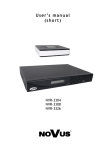
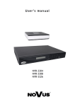
U s e r ’s m a n u a l
NVR-3304
NVR-3308
NVR-3326
NVR-3304, NVR-3308, NVR-3326 User’s manual ver.1.0
33
TABLE OF CONTENTS
1. FOREWORD INFORMATION .................................................................................... ..5
1.1. Network recorder’s technical data ..............................................................................5
08
TABLE OF CONTENTS
R-
1.2. Main characteristic................................................................................................... ...7
1.3. Package contents......................................................................................................... 7
NV
2. STARTING THE DEVICE .............................................................................................. 8
2.1. Electrical connection and other rear panel elements. ................................................. 8
ht
tp
://
ww
w
.e
-
ca
m
er
e.
ro
/
nv
r/
No
vu
s/
2.2. HDD mounting ......................................................................................................... 10
2.2.1. NVR-3304 HDD mounting ................................................................................... 10
2.2.2. NVR-3308 and NVR-3326 HDD mounting .......................................................... 12
2.3. Connecting power adapter.. ...................................................................................... 13
2.4. Connecting monitor .................................................................................................. 15
2.5. Camera and Network wiring .................................................................................... 15
2.6. Peripheral device connection.................................................................................... 17
3. OPERATING NVR ......................................................................................................... 19
3.1. Front panel description ............................................................................................. 19
3.2. Controlling via USB mouse ..................................................................................... 20
3.3. System operation ...................................................................................................... 21
3.4. Startup configuration ................................................................................................ 22
3.4.1. Configure HDD ................................................................................................ 22
3.4.2. Basic networking .............................................................................................. 22
3.4.3. Connecting cameras ......................................................................................... 23
4. NVR MENU ..................................................................................................................... 25
4.1. Live monitoring ........................................................................................................ 27
4.2. Reorder menu ........................................................................................................... 22
4.3. Searching and playing recorded video ..................................................................... 29
4.4. Backup records ......................................................................................................... 30
4.5. Setting English language .......................................................................................... 34
5. NVR CONFIGURATION ............................................................................................... 37
5.1. Video channel settings............................................................................................... 37
5.1.1. Basic channel settings ............................................................................... 37
5.1.2. Streaming settings ..................................................................................... 37
5.2. Snapshot .................................................................................................................... 38
5.3. Record configuration ................................................................................................. 39
5.4. Advanced network settings........................................................................................ 41
5.4.1. Net Apply .................................................................................................. 42
5.4.2. DDNS ........................................................................................................ 42
5.4.3. Email ........................................................................................................ 42
5.4.4. FTP ............................................................................................................ 43
5.4.5. NTP ........................................................................................................... 45
5.4.6. IP Filter...................................................................................................... 45
5.3.7. Net transfer ability ..................................................................................... 45
All rights reserved © AAT Holding sp. z o.o.
2
NVR-3304, NVR-3308, NVR-3326 User’s manual ver.1.0
ht
tp
://
ww
w
.e
-
ca
m
er
e.
ro
/
nv
r/
No
vu
s/
NV
R-
33
5.4.8. Alarm server ............................................................................................. 46
5.4.9. 3G ............................................................................................................. 46
5.4.10. P2P.......................................................................................................... 46
5.5. Alarm settings ..................................................................................................... 46
5.5.1. Motion detection alarm settings ............................................................... 46
5.5.2. Video lost.................................................................................................. 47
5.5.3. Alarm input ............................................................................................... 47
5.5.4. Alarm out .................................................................................................. 48
5.6. NVR abnormity alarms ............................................................................................. 49
5.7. Display ...................................................................................................................... 50
5.7.2. GUI ........................................................................................................... 50
5.7.2. Output mode ............................................................................................. 51
5.7.3. Tour config ............................................................................................... 51
5.8. Hard drive configuration ........................................................................................... 52
5.8.1. Formatting hard drive ............................................................................... 52
5.8.2. Hard drive mode settings .......................................................................... 53
5.8.3. HDD Record information ......................................................................... 54
5.8.4. Record backup .......................................................................................... 53
5.9. Status menu ............................................................................................................... 55
5.9.1. Manage online users ................................................................................. 55
5.10. Maintain menu ....................................................................................................... 56
5.10.1. Displaying log information ..................................................................... 56
5.10.2. Displaying NVR information ................................................................. 57
5.10.3. Updating NVR firmware ........................................................................ 57
5.10.4. Restoring default configuration .............................................................. 57
5.10.5. Auto-reboot ............................................................................................ 57
5.11. Managing users accounts ........................................................................................ 58
5.11.1. Adding user account ............................................................................... 59
5.11.2. Modify user settings ............................................................................... 59
5.11.3. Modify group ......................................................................................... 59
6. NETWORK OPERATIONS UTILIZING WEB BROSWER .................................... 60
6.1. Recommended PC specification for web browser connections ................................ 60
6.2. Establishing a connection ......................................................................................... 60
6.3. Remote access configuration ................................................................................... 62
6.4. Live monitoring interface. ........................................................................................ 63
6.5. Configure the NVR using web interface................................................................... 61
6.6. Playback ................................................................................................................... 68
6.7. Archiving records .................................................................................................... 70
6.8. Configurations of alarm display .............................................................................. 70
6.9. Display system information ..................................................................................... 70
6.10. Logout from web interface .................................................................................... 71
08
TABLE OF CONTENTS
All rights reserved © AAT Holding sp. z o.o.
3
NVR-3304, NVR-3308, NVR-3326 User’s manual ver.1.0
33
08
IMPORTANT SAFEGUARDS AND WARNINGS
ht
tp
://
ww
w
.e
-
ca
m
er
e.
ro
/
nv
r/
No
vu
s/
NV
R-
·
·
All rights reserved © AAT Holding sp. z o.o.
4
NVR-3304, NVR-3308, NVR-3326 User’s manual ver.1.0
08
FOREWORD INFORMATION
33
1. FOREWORD INFORMATION
1.1. Network recorder’s technical data
NVR-3304
Network Camera
Up to 4 channel in resolution 1920x1080(video + audio)
Camera/Protocol suport
NOVUS, ONVIF, RTSP
Main (split screen, full screen, sequence): 1 x HDMI, 1 x VGA, 1 x BNC
Audio Input/Output
1 x Line n (RCA) /1 x Line out (RCA)
Dualstreaming support
Yes*
RECORDING
H.264
s/
Compression
Resolution
1920 x 1080 and lower
Up to 120 fps (4 x 30fps for 1920 x 1080, 1280 x 720)
r/
No
vu
Speed
Streams Size
Up to 32Mb/s for the system
Recording Mode
Individual settings for: each day/hour (6 hourly ranges) for each camera, possibility of combining individual recording modes
Schedule
Individual settings for: each day, each hour, each camera, possibility of combining individual recording modes
Prealarm/postalarm
0 s - 30 s/ 300 s
DISPLAY
Resolution
Up to 1920 x 1080
Up to 120 fps (4 x 30fps)**,***
Speed
nv
PLAYBACK
Speed
Recorded Data Search
ro
/
BACKUP
Methods
File Format
STORAGE
e.
Internal HDD
Total Capacity
Internal Input/Output
Motion Detection
System Reaction to Alarm Events
ca
NETWORK
Network Interface
PC Software
Smartphone Software
Number of Connections/Bandwidth
Functions
AUXILIARY INTERFACES
USB
OPERATING SYSTEM
Operating mode
Installing 1 HDD 3,5” SATA
Support camera’s motion detection*
1 x Ethernet - RJ-45 socket, 10/100 Mbit/s
ONVIF (2.2/Profile S), DHCP, PPPOE, DDNS,SMTP,SNTP,FTP,UPnP,TCP/IP IPv4, UDP, HTTP, RTP/RTSP
Internet Explorer
IMSeye (for iPhone, Android,)
Up to 10 connections
Pan, tilt, zoom, preset *
2 x USB 2.0
Triplet
Polish, English and others
PC mouse (in-set included), network
://
OSD
AVI,DAV
Buzzer, E-mail , output activation, screen message, recording activation, PTZ function
ww
w
PTZ
USB port (HDD or Flash memory), network
-/-
.e
-
Network Protocols Support
By date/time
Support camera’s alarm input*
m
Camera Input/Output
Up to 120 fps (4 x 30fps for 1280 x 720)
Up to 60 fps ( 2 x 30 fps for 1920 x 1080)
4 TB
er
ALARM
System Diagnostic
Security
NV
Monitor Output
Control
R-
VIDEO / AUDIO
Automatic control of HDDs, network, network cameras lost
Password protection, IP filtering
tp
INSTALLATION PARAMETERS
Dimensions (mm)
215 (W) x 215 (D) x 46 (H)
Weight
0,8 kg (without HDD)
Power Supply
ht
12 VDC (100~240VAC/12VDC PSU In-set included)
Power Consumption
30 W (with 1 HDD)
Operating Temperature
-10 °C ~ 55°C
** Function capability depends of camera used , for details please check compatibility list. ** - For BNC output speed may be lower ***- Available with using dual streaming mode
All rights reserved © AAT Holding sp. z o.o.
5
NVR-3304, NVR-3308, NVR-3326 User’s manual ver.1.0
08
FOREWORD INFORMATION
NVR-3308
NVR-3326
Up to 8 channel in resolution 1920x1080 (video + audio)
Up to 26 channel in resolution 1280 x 720 (video + audio)
Camera/Protocol suport
Monitor Output
Audio Input/Output
NOVUS, ONVIF, RTSP
NOVUS, ONVIF, RTSP
Main (split screen, full screen, sequence):
1 x HDMI, 1 x VGA, 1 x BNC
Main (split screen, full screen, sequence):
1 x HDMI, 1 x VGA, 1 x BNC
1 x Line in (BNC) / 1 x Line out (BNC)
1 x Line in (BNC) / 1 x Line out (BNC)
Yes*
Yes*
Dualstreaming support
R-
Network Camera
33
VIDEO / AUDIO
Compression
NV
RECORDING
H.264
Resolution
H.264
1920 x 1080 and lower
1920 x 1080 and lower
Streams Size
Up to 780 fps (26 x 30fps for 1280 x 720)
Up to 480 fps (16 x 30fps for 1920 x 1080)
s/
Up to 240 fps (8 x 30fps for 1280 x 720)
Up to 240 fps (8 x 30fps for 1920 x 1080)
Speed
Up to 64Mb/s for the system
Up to 128Mb/s for the system
Time-lapse, Event (Alarm, Motion detection), manual
Time-lapse, Event (Alarm, Motion detection), manual
r/
No
vu
Recording Mode
Individual settings for: each day/hour (6 hourly ranges) for each camera, possibility of Individual settings for: each day/hour (6 hourly ranges) for each camera, possibility of
combining individual recording modes
combining individual recording modes
Schedule
Prealarm/postalarm
0 s - 30 s/ 300 s
DISPLAY
Up to 1920 x 1080
Resolution
Up to 240 fps (8 x 30fps) **,***
Speed
Up to 120 fps (4 x 30fps for 1280 x 720)
Up to 60 fps (2 x 30fps for 1920 x 1080)
Up to 390 fps (13 x 30fps for 1280 x 720)
Up to 180 fps (6 x 30fps for 1920 x 1080)
By date/time
nv
Recorded Data Search
BACKUP
USB port (HDD or Flash memory), network
File Format
AVI,DAV
STORAGE
By date/time
USB port (HDD or Flash memory), network
AVI,DAV
ro
/
Methods
Up to 1920 x 1080
Up to 780 fps (26 x 30fps) **,***
PLAYBACK
Speed
0 s - 30 s/ 300 s
Internal HDD
Installing 2 HDD 3,5” SATA
Installing up to 2 HDD 3,5” SATA
Total Capacity
8 TB
8 TB
e.
ALARM
4 / 1 relay
16 / 3 relay
Camera Input/Output
Support camera’s alarm input*
Support camera’s alarm input*
er
Internal Input/Output
Motion Detection
System Reaction to Alarm Events
Support camera’s motion detection*
Support camera’s motion detection*
Buzzer, E-mail, output activation, screen message, recording activation, PTZ function
Buzzer, E-mail, output activation, screen message, recording activation, PTZ function
Network Protocols Support
1 x Ethernet - RJ-45 socket, 10/100 Mbit/s + 4 x Ethernet - RJ-45 socket, 10/100/ Mbit
with IEEE 802.3 af PoE/
ONVIF (2.2/Profile S), DHCP, PPPOE, DDNS,SMTP,SNTP,
FTP,UPnP,TCP/IP IPv4, UDP, HTTP, RTP/RTSP
ca
Network Interface
m
NETWORK
PC Software
Number of Connections/Bandwidth
PTZ
Functions
USB
OPERATING SYSTEM
Operating mode
OSD
Control
Security
://
System Diagnostic
ww
w
AUXILIARY INTERFACES
Internet Explorer
Internet Explorer
IMSeye (for iPhone, Android)
IMSeye (for iPhone, Android)
.e
-
Smartphone Software
1 x Ethernet - RJ-45 socket, 10/100/1000 Mbit/
ONVIF (2.2/Profile S), DHCP, PPPOE, DDNS,SMTP,SNTP,
FTP,UPnP,TCP/IP IPv4, UDP, HTTP, RTP/RTSP
Up to 10 connections
Up to 10 connections
Pan, tilt, zoom, preset *
Pan, tilt, zoom, preset *
2 x USB 2.0
2 x USB 2.0
Triplex
Triplex
Polish, English and others
Polish, English and others
PC mouse, IR remote control (in-set included), network
PC mouse, IR remote control (in-set included), network
Automatic control of HDDs, network, network cameras lost
Automatic control of HDDs, network, network cameras lost
Password protection, IP filtering
Password protection, IP filtering
360 (W) x 48 (H) x 260 (L)
360 (W) x 48 (H) x 260 (L)
2 kg (without HDD)
2 kg (without HDDs)
INSTALLATION PARAMETERS
Dimensions (mm)
tp
Weight
Power Supply
ht
Power Consumption
Operating Temperature
12 VDC (100~240VAC/12VDC PSU) +
48 VDC (100~240VAC PUS) In-set included
40 W (with 2 HDDs)
+ 60 W PoE power supply
12 VDC (100~240VAC/12VDC PSU In-set included)
40 W (with 2 HDDs)
-10 °C ~ 55°C
-10 °C ~ 55°C
** Function capability depends of camera used , for details please check compatibility list. ** - For BNC output speed may be lower ***- Available with using dual streaming mode
All rights reserved © AAT Holding sp. z o.o.
6
NVR-3304, NVR-3308, NVR-3326 User’s manual ver.1.0
08
FOREWORD INFORMATION
·
Support ONVIF and RTSP protocol
·
Monitor output: HDMI, VGA, BNC
·
Support 2 HDDs 3,5” inside (NVR-3304 1 HDD)
R-
33
1.2. Main characteristics
4 video and audio channels for network cameras
·
Recording speed up to 120 fps in 1920 x 1080 resolution
·
Supported resolution up to 1920x1080
NVR-3308
r/
No
vu
·
s/
NV
NVR-3304
8 video and audio channels for network cameras
·
Recording speed up to 240 fps in 1920 x 1080 resolution
·
Supported resolution up to 1920x1080
nv
·
NVR-3326
26 video and audio channels for network cameras
·
Recording speed up to 780 fps in 1280 x 720 resolution
·
Supported resolution up to 1920x1080
e.
ro
/
·
er
1.3. Package contents
m
Unpack the device carefully. After unpacking, please ensure that package contains the following items:
Network Video Recorder: NVR-3304 / NVR-3308 / NVR-3326
·
IR remote control (only in : NVR-3308,NVR-3326)
·
12 VDC Power supply ( 48VDC PoE power supply for NVR-3308)
·
SATA cables for HDDs (NVR-3304 1 cable for HDD)
·
USB Mouse
·
Accessory bag
·
User’s manual (short)
·
CD with a full version of user’s manual and software tools
ww
w
.e
-
ca
·
://
If any of the elements has been damaged during transport, pack all the elements back into the original
packaging and contact your supplier.
tp
CAUTION:
ht
If the device was brought from a location with lower temperature, please wait until it reaches the
temperature of location it is currently in. Turning the device on immediately after bringing it
from a location with lower ambient temperature is forbidden, as the condensing water vapour
may cause short-circuits and damage the device as a result.
All rights reserved © AAT Holding sp. z o.o.
7
NVR-3304, NVR-3308, NVR-3326 User’s manual ver.1.0
2.
STARTING THE DEVICE
2.1
Electrical connection and other rear panel elements.
33
08
STARTING THE DEVICE
7
1
s/
6
r/
No
vu
8
NV
R-
NVR-3304 back panel
3
4
5
ro
/
nv
2
HDMI:
Main monitor connectors, use HDMI cable to connect monitor.
2.
VGA:
Main monitor connectors, use D-SUB VGA cable to connect monitor.
3.
AUDIO IN:
Audio mono inputs for connecting microphone*.
4.
USB:
2 x USB 2.0 ports for external Flash memory, mouse connection and
other USB compatible devices.
5.
DC 12V:
12 VDC Power supply socket.
6.
VIDEO OUT:
BNC video output.
7.
AUDIO OUT:
8.
NET:
ca
m
er
e.
1.
Port for connecting local speaker with pre-amplifier.
.e
-
RJ-45 connector port for connecting to the LAN network .
ht
tp
://
ww
w
* audio input will be available in the future.
All rights reserved © AAT Holding sp. z o.o.
8
NVR-3304, NVR-3308, NVR-3326 User’s manual ver.1.0
08
STARTING THE DEVICE
2
3
4
5
8
9
11
10
s/
7
r/
No
vu
6
NV
R-
1
33
NVR-3308 back panel
12
NVR-3326 back panel
2
3
nv
1
ro
/
6
7
4
8
9
5
10
MIC IN:
Audio mono inputs for connecting microphone*.
2.
AUDIO OUT:
Port for connecting local speaker with pre-amplifier.
3.
VIDEO OUT:
BNC video output.
4.
USB:
USB 2.0 port for external Flash memory, mouse connection and
other USB compatible devices.
5.
POWER SW:
NVR power switch, plug the power cord and turn this switch on.
6.
HDMI:
7.
VGA:
8.
ALARM & RS485:
Alarm input and output interface*.
9.
NET:
RJ-45 connector port for connecting to the LAN network .
10.
12 VDC POWER
12 VDC power supply socket
11.
PoE :
4 x RJ-45 connections ports with PoE support
12.
PoE POWER:
ca
m
er
e.
1.
Main monitor connectors, use HDMI cable to connect monitor.
ww
w
.e
-
Main monitor connectors, use D-SUB VGA cable to connect monitor
48 VDC PoE power supply socket
ht
tp
://
* RS485 and audio input will be available in the future.
All rights reserved © AAT Holding sp. z o.o.
9
NVR-3304, NVR-3308, NVR-3326 User’s manual ver.1.0
08
STARTING THE DEVICE
33
2.2 HDD mounting
Novus NVR-3308 and NVR-3326 supports 2 internal SATA HDDs (NVR-3304 1 HDD).
NV
R-
WARNING!
After installing the hard disk recorder automatically formats it during boot time, all data on the
disk will be erased.
r/
No
vu
s/
Prior to removing cover of the DVR please unplug the power cord first
In order to find information regarding the compatible models of HDDs and their maximum
capacities, please contact Novus distributor or check the information presented at
www.novuscctv.com. AAT HOLDING Company is not responsible for any problems resulting
from using not recommended hard drives.
The list of compatible HDDs contains all the HDDs that can be used with a given DVR including
HDDs designed for office use - so called desktop disks. However, due to the fact that reliability of
the recording process and data safety are paramount factors of any CCTV system, we strongly
advise to use HDDs designed for continuous (24/7) operation.
ro
/
nv
You need to format disks to if they were used in a different device. All data saved on HDD prior
to format will be lost.
2.2.1 NVR-3304 HDD mounting
ht
tp
://
ww
w
.e
-
ca
m
er
e.
In order to mount HDD, please unscrew the two screws on the NVR bottom (depicted below) and
remove the cover.
All rights reserved © AAT Holding sp. z o.o.
10
NVR-3304, NVR-3308, NVR-3326 User’s manual ver.1.0
08
STARTING THE DEVICE
r/
No
vu
s/
NV
R-
33
Set the HDD on the cover with connection ports directed into cover holes used to fasten it into the
housing.
er
e.
ro
/
nv
Use 4 screws supplied with NVR to attach HDD to the cover.
ht
tp
://
ww
w
.e
-
ca
m
Put the cover with HDD into the housing. Connect data and power connector and then close the cover.
Secure the cover with two screws previously unscrewed from the housing.
All rights reserved © AAT Holding sp. z o.o.
11
NVR-3304, NVR-3308, NVR-3326 User’s manual ver.1.0
08
STARTING THE DEVICE
33
2.2.2 NVR-3308 and NVR-3326 HDD mounting
ro
/
nv
r/
No
vu
s/
NV
R-
For installing HDDs unscrew 6 screws according to picture below and remove the cover.
ht
tp
://
ww
w
.e
-
ca
m
er
e.
The figure below indicates holders to mount hard drives. Screw the HDD drives in selected places.
All rights reserved © AAT Holding sp. z o.o.
12
NVR-3304, NVR-3308, NVR-3326 User’s manual ver.1.0
08
STARTING THE DEVICE
nv
r/
No
vu
s/
NV
R-
33
Then connect the power supply and use the supplied cables to connect the SATA drives to the NVR
motherboard .
ro
/
Replace the cover and secure it with 6 screws.
2.3. Connecting power adapter
ww
w
.e
-
ca
m
er
e.
NVR-3304
ht
tp
://
Connect the cable end from power supply supplied with the NVR into the DC 12V power socket . Plug
power supply into mains, device should start after connecting to power source. Wait about 2 minutes to
start working with NVR.
All rights reserved © AAT Holding sp. z o.o.
13
NVR-3304, NVR-3308, NVR-3326 User’s manual ver.1.0
08
STARTING THE DEVICE
r/
No
vu
s/
NV
R-
33
NVR–3308
nv
Connect the cable end from the 12 V DC power supply supplied with NVR into socket labelled DC
12V in NVR. In order to supply electricity into PoE ports, cable from the 48 VDC power supply must
be connected to the socket marked DC48 in NVR. Connect power supply to the mains and set power
switch to “-” position to start the device. Wait about two minutes till initialization process ends and
start working with NVR . If you turn off NVR using SHUTDOWN button use ON/OFF button from
the front panel to turn on the device.
ca
m
er
e.
ro
/
NVR–3326
ww
w
.e
-
Connect the 12V DC power supply cable end to power socket labelled DC 12V in NVR. Connect
power supply to the mains and set power switch to “-” position to start the device. Wait about two
minutes till initialization process ends and start working with NVR. If you turn off NVR using
SHUTDOWN button use ON/OFF button from front panel to turn on the device.
CAUTION:
Make connection when the power is not applied.
Make sure that power adapter is placed near of NVR and secured from accidental disconnection.
tp
://
If the device was brought from a location with lower temperature, please wait until it reaches the
temperature of location it is currently in. Turning the device on immediately after bringing it
from a location with lower ambient temperature is forbidden, as the condensing water vapour
may cause short-circuits and damage the device as a result.
ht
Before starting the device familiarize yourself with the description and the role of particular
inputs, outputs and adjusting elements that the device is equipped with.
All rights reserved © AAT Holding sp. z o.o.
14
NVR-3304, NVR-3308, NVR-3326 User’s manual ver.1.0
08
STARTING THE DEVICE
This product supports following interfaces for main monitor: HDMI, VGA and BNC.
33
2.4. Connecting monitor
R-
For HDMI and VGA outputs following resolutions are supported: 1024x768, 1280x1024, 1280x720,
1920x1080.
NV
After changing resolution you have to confirm it by clicking OK. NVR will be restarted in order to
change the resolution.
r/
No
vu
s/
You can use the HDMI <> DVI converter to connect to the DVI monitor. HDMI<>DVI converter is
not included and you can buy it separately.
2.5. Camera and Network wiring
ro
/
nv
To connect compatible IP cameras to the NVR you have to use additional network switch. By using
Ethernet cables connect the cameras and NVR to the switch, like on image below. Please notice that
the Ethernet connection is effective within 100 meter distance.
ht
tp
://
ww
w
.e
-
ca
m
er
e.
NVR-3304
All rights reserved © AAT Holding sp. z o.o.
15
NVR-3304, NVR-3308, NVR-3326 User’s manual ver.1.0
08
STARTING THE DEVICE
R-
33
NVR-3308 has 4 bulid-in RJ-45 ethernet ports with PoE support which can be used for connecting
cameras. Please notice that the Ethernet connection is effective within 100 meter distance.
er
e.
ro
/
nv
r/
No
vu
s/
NV
NVR-3308
ht
tp
://
ww
w
.e
-
ca
m
NVR-3326
All rights reserved © AAT Holding sp. z o.o.
16
NVR-3304, NVR-3308, NVR-3326 User’s manual ver.1.0
08
STARTING THE DEVICE
33
Note:
R-
To ensure recording stability from an overloaded network traffic, or unauthorised access, it is
strongly recommended to create separate network, secured by router firewall from the user network.
r/
No
vu
s/
NV
Before adding any camera to the NVR, you have to configure its network settings using computer
like it is described in Camera User Manual. For the next steps of camera and network configurations
please check chapter 3.4. Startup configuration.
2.6. Peripheral device connection
Connecting audio ports
·
Audio output signal normally are above 200mV 1kΩ. You can connect the low impedance earphone,
or power amplifier with the external speakers.
Connecting USB devices
nv
·
ro
/
NVR has 2 x USB 2.0 ports for external Flash memory, mouse connection and other USB compatible
devices.
Connecting alarms ports
·
e.
NVR-3308 and NVR-3326 have local alarm input and output. For connecting them please refer the
table below.
ww
w
.e
-
ca
m
er
NVR-3308 have 4 alarm inputs and 1 alarm output.
ALARM
INPUTS
2
3
RS 485
GND
NO
C
GND
+
-
5
6
7
8
9
10
4
tp
1
A. IN 2 A. IN 3 A. IN 4
://
A. IN 1
ALAM
OUTPUT
ht
To activate alarm in you have to simply connect alarm input (1,2,etc) to GND cable.
Alarm output is a relay with 2 connectors NO and C.
Note: RS485 will be available in the future.
All rights reserved © AAT Holding sp. z o.o.
17
NVR-3304, NVR-3308, NVR-3326 User’s manual ver.1.0
08
STARTING THE DEVICE
r/
No
vu
s/
NV
R-
33
NVR-3326 series has 16 local alarm inputs and 3 alarm outputs.
nv
For connecting them please refer the table below:
3
A. IN A. IN
1
2
16
17
A. IN
3
18
4
5
6
7
e.
2
ALARM
OUTPUTS
A. IN GND A. IN A. IN A. IN A. IN GND NO2
12
13
14
15
16
8
9
10
11
A. IN GND A. IN A. IN A. IN A. IN GND NO1
4
5
6
7
8
19
21
22
23
24
25
ALARM
INPUTS
26
ww
w
://
To activate alarm in you have to simply connect alarm input (1,2,etc) to GND cable.
tp
Alarm output is a relay with 2 connectors NO and C.
Note:
ht
RS485 will be available in the future.
All rights reserved © AAT Holding sp. z o.o.
18
C2
12
NO3 C3 NC3
14
15
C1 GND
+
-
27
29
30
ALARM
OUTPUTS
.e
-
ca
ALARM
INPUTS
20
er
1
A. IN
11
m
A. IN A. IN
9
10
ALARM
INPUTS
ro
/
ALARM
INPUTS
13
28
RS 485
NVR-3304, NVR-3308, NVR-3326 User’s manual ver.1.0
08
NVR OPERATING
33
3. NVR OPERATING
3.1. Front panel description
NV
2
ww
w
.e
-
ca
m
er
e.
ro
/
nv
r/
No
vu
s/
1
R-
NVR-3304
Power supply indicator
2. HDD LED:
HDD operation indicator
ht
tp
://
1. POWER LED:
All rights reserved © AAT Holding sp. z o.o.
19
NVR-3304, NVR-3308, NVR-3326 User’s manual ver.1.0
08
NVR OPERATING
NVR-3308 and NVR-3326
8
33
7
2
4
5
r/
No
vu
1. LCD :
3
s/
1
NV
R-
6
ww
w
.e
-
ca
m
er
e.
ro
/
nv
A IP address of the device, the clock, the external alarm channel, error status code of the machine,
remote address, internal temperature of the chassis are displayed there
B. Network Connection status.
C. HDD status and numbers. “E” and flash label refer HDD error.
D. Cycling display the recording status and motion detection (distinguish by “REC” and “MOVE”).
2. IR Receiver : Receive the remote control signal.
3. ESC :
Back to previous menu, operation cancel;
Back to live view when playing back records.
4. Direction :
Up/Down: Move up or down. Change the settings and increase or decrease the
digital. Left/Right: Control the playback control bar of the records.
5. Enter :
Confirm the operations.
Jump to the default button.
Enter the menu.
6. Fn :
The button displays PTZ control and image color when in a single-screen
monitoring.
Simultaneously press the Fn key and the direction key to complete the settings with
the dynamic monitoring area.
Press the Fn key to empty all contents of the edit box.
Press the key to switch between the digital case in English, Chinese input.
Special with the function of each menu page prompts.
7. USB :
To connect the mouse or Flash drives.
8. ON/OFF :
Power on/off
ht
tp
://
3.2. Controlling via USB mouse
It is possible to control NVR via an USB mouse connected to the USB port. Double-clicking on any
camera in 2x2, 3x3 display mode switches the display to full-screen mode. Subsequent double-click
returns to previous display mode. Click the right key of mouse to bring up menu with basic functions.
Select MAIN MENU from that menu to have access other functions. To exit the menu press right
mouse button or press ESC button in NVR-3308 and NVR-3326 front panel.
All rights reserved © AAT Holding sp. z o.o.
20
NVR-3304, NVR-3308, NVR-3326 User’s manual ver.1.0
08
NVR OPERATING
33
3.3. System operations
r/
No
vu
s/
NV
R-
To manipulate or access menus of the NVR, you should log in first. Press the right mouse button and
select one of the items on the menu such as the MAIN MENU to induce the login window. You can
also press ENTER button on front panel of NVR-3308 and NVR-3326 to display login window.
nv
From drop down menu select user name and enter password. Entering the characters is possible using
the virtual keyboard. Double click on the password entry field to call it. To call it the front panel press
the Fn button.
ro
/
Default username /password is “root”/”pass”
For safety reasons, it is recommended to change default user name and password.
er
e.
If the language of the recorder was reset see chapter 4.5 describing the procedure for changing
the language.
main menu and
ca
m
In order to shutdown NVR you should click the SHUTDOWN icon from the
then click the SHUTDOWN
button.
from the main menu and
.e
-
In order to reboot NVR you should click the SHUTDOWN icon
then click the RESTART SYSTEM icon
.
://
ww
w
To prevent unauthorized access, it is recommended to log out when you finish operating with menu.
To do that click the SHUTDOWN icon
from the main menu and then select MENU LOGOUT
icon
.
tp
NOTE: By default NVR will log off user after 10 minutes of inactivity. Select SYSTEM icon from
MAIN MENU and then click on on BASICAL icon to modify AUTO LOGOUT time. (0 means no
logging off)
ht
CAUTION:
If you turn off the system in an abnormal manner such as removing the power cord while the
system is working, the disk will acquire or increase the numbers of bad sectors, causing data
loss and shortened life cycle of the disk.
All rights reserved © AAT Holding sp. z o.o.
21
NVR-3304, NVR-3308, NVR-3326 User’s manual ver.1.0
08
NVR OPERATING
33
3.4. Startup configuration
R-
Prior to using NVR for the first time, initial setup is strongly advised. Before you connect the IP
cameras to the NVR, please set up network and stream parameters of IP cameras using computer.
Note:
r/
No
vu
s/
NV
For suggested values for IP camera setting please refer to the “Cameras Compatibility Table”
available as separate file in CD added to NVR. If you will set wrong values some problems may
appear: the NVR cannot search the IP camera, the stream cannot be connected, the image is not fluent,
the image quality is bad and so on.
Set basic NVR configuration :
From the MAIN MENU click SYSTEM icon
following parameters :
and then click on BASICAL
icon to set
SYSTEM TIME - set up correct time and date
·
DST—to set daylight saving functions
·
·
DATE FORMAT - Modify the date display format
DATE SEPARATOR - set the separator for date
·
TIME FORMAT - 12-hr or 24-hr display mode
·
TIME ZONE - set time zone
·
LANGUAGE - allow to select preferred language
·
VIDEO FORMAT- PAL or NTSC (required for using BNC video output)
·
DVR No.– set this value to be distinguishable from among several NVR with remote
control
·
AUTO LOGOUT - set standby time after user will be logout. (0—means no logout)
·
CHANNEL MODE - to select channel decoding configuration
.e
-
ca
m
er
e.
ro
/
nv
·
3.4.1. Configure HDD
ww
w
From the MAIN MENU select SYSTEM icon
and click on STORAGE icon
. Select check
the hard drive and press SET button to set HDD as read/write, read-only or redundancy mode. If it is
unformatted you have to select HDD and press FORMAT button to format HDD.
://
CAUTION: Hard disk format operation result in the loss of video data
3.4.2. Basic networking
From the MAIN MENU click NETWORK icon
BASE tab and set following parameters:
tp
IV.
and go to the NETWORK section. Select
IP ADDRESS (by default it is 192.168.1.100)
·
SUBNET MASK (by default it is 255.255.255.0).
ht
·
All rights reserved © AAT Holding sp. z o.o.
22
NVR-3304, NVR-3308, NVR-3326 User’s manual ver.1.0
08
NVR OPERATING
33
Note:
NV
R-
Be sure that IP addresses and subnet mask of the NVR and the IP cameras are in the same network
subnet (e.g. for the NVR IP address 192.168.1.100, and mask 255.255.255.0 appropriate address for
the camera ranges from 192.168.1.1 to 192.168.1.254, for example 192.168.1.201). It is not allowed to
set the same addresses for multiple devices
r/
No
vu
s/
Optionally if you are going to connect NVR to the Internet (for remote access, sending email, etc) set
up :
·
GATEWAY,
·
FIRST and ALTERNATE DNS.
You can alternatively check DHCP mode (DHCP server is required in this method in targeting
network) then all settings will be set up automatically. When you use DHCP server check IP address
lease and its linking with NVR MAC address to avoid changing or losing IP address during device
operation or network/DHCP server breakdown. This solution is not recommended for security systems.
3.4.3. Connecting cameras
ww
w
.e
-
ca
m
er
e.
ro
/
nv
To configure cameras to work with NVR click on VIDEO button from MAIN MENU
NET CHANNEL tab.
://
You can input data for connecting camera manually or search network for cameras available.
Set following fields to connect with camera.
PROTOCOL TYPE -set protocol supported by camera ( default ONVIF )
ht
·
CHANNELS - select desired channel number
tp
·
·
REMOTE IP - IP address of the camera
All rights reserved © AAT Holding sp. z o.o.
23
and go to
NVR-3304, NVR-3308, NVR-3326 User’s manual ver.1.0
08
NVR OPERATING
PORT - Enter the port used to transfer data from the camera.
·
USERNAME - Enter the user name used to connect to the camera.
·
PASSWORD - Enter the user name used to connect to the authorization of the camera.
·
REMOTE DETECT - After completing of the above settings, click the DETECT button. NVR
will connect with the camera and return the connection status.
·
REMOTE CHANNEL - When connecting to the camera set this number to 1.
Check the OPEN checkbox to turn the channel on.
m
er
e.
ro
/
nv
r/
No
vu
To search for available cameras click on SEARCH button.
s/
NV
R-
33
·
.e
-
ca
Make sure that protocol type is set to ONVIF and press SERACH button. Wait for a while until the
NVR find available cameras. Double-click on the selected camera to transfer settings to the NET
CHANNEL tab. Then you can input valid password and username and click DETECT to check if NVR
is able to connect with camera.
ww
w
Make sure to check the OPEN check box to activate channel and press APP. button to enable camera .
To copy camera settings to other channels click COPY button and select the channels which do you
want to copy settings. Please note that IP address is also copied, so you have to change it manually in
copied channels.
ht
tp
://
To save settings and exit menu press OK button.
All rights reserved © AAT Holding sp. z o.o.
24
NVR-3304, NVR-3308, NVR-3326 User’s manual ver.1.0
08
NVR MENU
33
4. NVR MENU
POP-UP MENU
e.
ro
/
nv
r/
No
vu
s/
NV
R-
4.1. Live monitoring
er
VIDEO WINDOWS
m
As soon as the NVR completes its initialization process, it will enter the real-time monitoring image.
ca
Displaying all cameras simultaneously is the default mode. Press NVR up or down button on the front
panel or remote controller to change display mode (NVR-3308 and NVR-3326).
.e
-
You can also use mouse to change camera view. Select desired channel on the split screen and press the
left mouse button to display it in a single view.
By pressing right mouse button on the view screen you can invoke pop-up menu with basic functions.
ww
w
1. Select display view. Single channel or split screens
1
2. Enables PTZ control for selected channel
3. Adjust image color hue, saturation, gain, white-level parameters
://
4. Search records by selected time, channel, record type
5. Mange basic recording settings
tp
6. Manage basic alarm out put settings
ht
7. Monitor connection and display stream information
8. Opens NVR Main Menu
All rights reserved © AAT Holding sp. z o.o.
25
2
3
4
5
6
7
8
NVR-3304, NVR-3308, NVR-3326 User’s manual ver.1.0
SYSTEM TIME
er
m
INFORMATION ICONS
e.
ro
/
nv
r/
No
vu
s/
NV
R-
CHENNEL ERROR INFOMRATION
33
08
NVR MENU
ca
ICONS
.e
-
Channel recording
Signal loss
ww
w
Motion detection alarm
Audio on/off
Channel block in tour dipslay
ht
tp
://
Tour channel display
All rights reserved © AAT Holding sp. z o.o.
26
NVR-3304, NVR-3308, NVR-3326 User’s manual ver.1.0
08
NVR MENU
Icon
Descrption
NV
Name
R-
33
4.2. Recorder menu
After selecting the MAIN MENU from OSD the MAIN MENU windnow appears providing access to
the main functions of the recorder.
Search for and playback recorded video files by date/time,
alarms or motion.
VIDEO
Configure channel name, encode, snap and net channel.
RECORD
Record related and record plan configure.
NETWORK
Setup network parameters: IP address, subnet mask, default
gateway, TCP/IP ports.
PTZ
Configure PTZ cameras: protocol, communication parameters, and communication address. (Function not available)
m
er
e.
ro
/
nv
r/
No
vu
s/
SEARCH
.e
-
ca
ALARM
ww
w
SYSTEM
Configure System Time,Display,Abnormity,Harddisk status;
recording bitrate; system access logs; current online users.
Logout the OSD menu or restart the system. After idle for
standby time(no input),the system will exit OSD.
ht
tp
://
SHUTDOWN
Display exterior alarm, motion detecton, video loss alarm
state.
All rights reserved © AAT Holding sp. z o.o.
27
NVR-3304, NVR-3308, NVR-3326 User’s manual ver.1.0
08
NVR MENU
Description
R-
Icon
NV
Name
33
Choosing the SYSTEM icon opens menu window with recorders system settings
Configure time and display format;language;configure
DVR remote control address.
DISPLAY
Settings for GUI and monitoring parameters.
STORAGE
HDD management and record backup management.
ABNORMITY
Abnormal parameter setup including HDD error, network error and IP conflict.
e.
ro
/
nv
r/
No
vu
s/
BASICAL
Display recording bitrate;User (local and online) administration.
m
er
STATUS
Display system log;version; configure default and automatic maintenance.
Account managment
Settings for serial port function and baud rate. (Function
not available)
ht
tp
://
RS232
ww
w
ACCOUNT
.e
-
ca
MAINTAIN
All rights reserved © AAT Holding sp. z o.o.
28
NVR-3304, NVR-3308, NVR-3326 User’s manual ver.1.0
08
NVR MENU
NV
R-
33
4.3. Searching and playing recorded video
To start searching the recordings select press right menu button on view screen and select SEARCH
from pop-up menu. You can also select SEARACH
icon from MAIN MENU. Then following
window will appear:
r/
No
vu
s/
10
e.
ro
/
nv
9
6
m
er
1
7
8
5
ca
4
.e
-
2
3
1.Playback control - Play/Pause,Play backward,Stop,Slow Playback, Fast Playback, Next Frame.
ww
w
2.Record synchronization - Synchronization of playing time for all channels
3.Record type selection - All type, Normal (green), Alarm (Pink), Motion(Yellow)
4.Time graph - Let you view and select records
://
5.Full Screen mode - Allow to view the recording in full screen mode
6. Circle playback - Play the recordings in the loop
tp
7.Next/Prev. Channel - let you change channel in active window
8. Show file list - Displays a list of recordings
ht
9. Channel selector - selects cameras for playback
10. Calendar - selects day of recordings
All rights reserved © AAT Holding sp. z o.o.
29
NVR-3304, NVR-3308, NVR-3326 User’s manual ver.1.0
08
NVR MENU
NV
R-
33
In this window you can view recording by selected channel and time. In calendar section days for
which the recorder contains the recordings are highlighted in green. Press left mouse button on desired
day. Then select desired channels numbers to display. Time graph should be displayed showing
recordings for selected channels. (When you choose more than 4 channels only one time graph is
2
displayed showing recording from active window). Colours on the graph represents the type of
recordings.(Green - Normal ,Pink-Alarm,Yellow-Motion detection).
s/
To start playback, press the graph at the selected time or press play button to start playing from the
beginning of that day. It is possible to synchronize time of playback or you can view up to 4 channels
with independent time selection.
r/
No
vu
4.4. Backup records
Users may copy recordings via USB into flash memory. NVRs allow to copy the recordings in
following formats: AVI, DAV. To find the files for copying, select that displays file list button.
TIME SELECTOR
SEARCH BUTTON
FILE SELCTOR
m
5
er
e.
ro
/
nv
WINDOW SELECTOR
ww
w
.e
-
ca
55
://
FILE LIST NAVIGATOR
ht
tp
FILE INFORMATION
BACK
BACKUP
All rights reserved © AAT Holding sp. z o.o.
30
NVR-3304, NVR-3308, NVR-3326 User’s manual ver.1.0
08
NVR MENU
NV
R-
33
From the top you can select time range and press search button to display files from that range. When
you click on the file at the bottom of the file list window displays information about the start and end
time of the recordings, and file size. Click on the checkbox to the left of the file in file selector window to set it as a file to backup. You can select multiple files from different channels. When you make
a selection, insert USB stick into USB port, and press the backup button to open backup menu.
r/
No
vu
s/
USB DRIVE INFORMATION
er
e.
ro
/
nv
AVI CHECKBOX
ww
w
.e
-
ca
m
FILE INFORMATION
DISK SPACE INFORMATION
START BACKUP
ht
tp
://
At the top of the menu, you should see information about the USB device. You can check the AVI
checkbox to save recordings in AVI format. The window below displays information about the selected files. If a USB drive is not enough space, you can deselect files for recording. Afters file selection is done press START button to start copying files. During this time you will see a progress bar and
estimated remaining time to completion of the operation. After copying selected files, the message
informing about the end of the backup process will be displayed.
All rights reserved © AAT Holding sp. z o.o.
31
NVR-3304, NVR-3308, NVR-3326 User’s manual ver.1.0
08
NVR MENU
R-
33
The second method for copying is available by clicking SYSTEM icon from MAIN MENU and then
clicking STORAGE icon. Select BACKUP tab to display detected USB devices. Insert pendrive into
USB port and press DETECT button. The device should be displayed in device information window.
It is possible to format the device by clicking ERASE button.
WARNING :
NV
All stored data are erased during HDD format.
s/
To begging selecting the recordings press BACKUP button.
ww
w
.e
-
ca
m
er
e.
ro
/
nv
r/
No
vu
USB DEVICE INFORMATION
ht
tp
://
STOP COPYING
FORMAT USB
DEVICE
BACKUP
USB DEVICE DISCOVERY
All rights reserved © AAT Holding sp. z o.o.
32
NVR-3304, NVR-3308, NVR-3326 User’s manual ver.1.0
08
NVR MENU
33
RECORD TIME SELECTION
AVI FORMAT
CHANNEL
REMOVE ALL
ADD SELECTION
START COPY
m
er
e.
ro
/
nv
r/
No
vu
s/
NV
R-
RECORD TYPE
ca
FILE LIST
BAKUP window allows selecting recordings by :
date and time of recording
·
recording type
·
Channel
ww
w
.e
-
·
ht
tp
://
Select the above parameters and press ADD button to add flies to file list. The warring message appear if the recorder is unable to find the recordings. It is possible to add files to list several time. REMOVE ALL button clears file selection list. Checking AVI checkbox enables saving records in AVI
format. After completing the selection press STRT button to begin copying process. At the bottom of
the window bar displaying copying progress should be displayed. The process ended with displaying
the window indicating the success of the backup.
All rights reserved © AAT Holding sp. z o.o.
33
NVR-3304, NVR-3308, NVR-3326 User’s manual ver.1.0
08
NVR MENU
33
4.5 Setting English language
The procedure presented below shows how to go back to the English language in the NVR
R-
menu in case of selecting any other language by mistake.
er
e.
ro
/
nv
r/
No
vu
s/
NV
1. Press right mouse button on preview window and select last position from pop-up menu.
m
2. Log in to the NVR with corresponding password for the user who has permissions to change system
settings. Press the left button to log in.
ht
tp
://
ww
w
.e
-
ca
The default data to the user's login is : user: root , password : pass
All rights reserved © AAT Holding sp. z o.o.
34
NVR-3304, NVR-3308, NVR-3326 User’s manual ver.1.0
08
NVR MENU
r/
No
vu
s/
NV
R-
33
3. Select second icon from right in bottom row (SYSTEM).
.e
-
ca
m
er
e.
ro
/
nv
4. Select first icon from the left in the upper row (PODSTAWOWE).
ht
tp
://
ww
w
5. Select the seventh menu position (JĘZYK) from the top and from the drop-down list, select the
first item.
All rights reserved © AAT Holding sp. z o.o.
35
NVR-3304, NVR-3308, NVR-3326 User’s manual ver.1.0
08
NVR MENU
ro
/
nv
r/
No
vu
s/
NV
R-
33
6. Select the first button on the right bottom (ZASTOSUJ) of the window
ht
tp
://
ww
w
.e
-
ca
m
er
e.
7. When the confirmation window appears please select right button (OK) NVR will reboot. After
r
e
s
t
a
r
t
i
n
g
English language should be set.
All rights reserved © AAT Holding sp. z o.o.
36
NVR-3304, NVR-3308, NVR-3326 User’s manual ver.1.0
08
NVR MENU
33
5. NVR CONFIGURATION
5.1. Video channel settings
For changing video settings choose VIDEO icon
scribed in chapter 3.4.3.
R-
from MAIN MENU. Network settings are de-
m
er
e.
ro
/
nv
r/
No
vu
s/
NV
5.1.1. Basic channel settings
ww
w
.e
-
ca
The following parameters are available in BASIC tab :
·
CHANNEL– selects channel for configuration
·
CHANNEL NAME - allows you to change the name of the channel
·
CHANNEL DISPLAY - function is not available
·
TIME DISPLAY - function is not available
·
TIME SYNCHRONIZATION - synchronize time in camera with NVR system time
·
VIDEO COVER - function is not available
·
PREVIEW - function is not available
·
MONITOR - function is not available
://
To save settings press APP button. To save setting and exit menu press OK button. DEFAULT button
sets back default setting. COPY button allows to copy current setting to other channels.
ht
tp
5.1.2. Streaming settings
ENCODING tab allows to configure video streaming from cameras. Main stream is used for recording
and single video preview, second stream is used for viewing in screen split mode.
All rights reserved © AAT Holding sp. z o.o.
37
NVR-3304, NVR-3308, NVR-3326 User’s manual ver.1.0
08
NVR MENU
er
e.
ro
/
nv
r/
No
vu
s/
NV
R-
33
WARRING : Please check in camera compatibility table available in the CD added to the NVR
if camera supports this functionality. Suggested stream parameters are in compatibility table.
Setting incorrect values may cause problems with display and recording streams.
ww
w
.e
-
ca
m
The following fields are used to configure video stream parameters :
·
CHANNEL - select channel for configuration
·
COMPRESSION - H.264 for default
·
RESOLUTION - select the resolution stream
·
FRME RATE (FPS) - selects the frame per second stream settings
·
BIT RATE CONTROL - select constant bit rate (CBR) mode or variable bit rate mode (VBR)
for stream operation
·
QUALITY - lets choose video compression modes from six available levels
·
BIT RATE - video stream bitrate settings.
://
The parameter values are taken from the cameras because setting are dependent on camera model or
camera firmware To save the settings, please select the APPLY button or OK button. To refresh the
settings, select the Refresh button.
ht
tp
5.2. Snapshot
The snapshot tab allow to configure capture settings. Function will be available in the future
All rights reserved © AAT Holding sp. z o.o.
38
NVR-3304, NVR-3308, NVR-3326 User’s manual ver.1.0
08
NVR MENU
ht
tp
://
ww
w
.e
-
ca
m
er
e.
ro
/
nv
r/
No
vu
s/
NV
R-
33
5.3. Record configuration
Choose RECORD icon from MAIN MENU to configure record settings. It allows to configure the
following parameters :
·
RECORD MODE : Schedule - Recording is controlled by schedule
Manual - turns on recording manually on selected channels
Stop - turns off recording manually on selected channel
·
RECORD EXPIRATION TIME - Time at which the recordings will be erased. 0 means no
term of validity (data will be erased from the oldest recording).
·
RECORD PACKED TIME - The maximum recording time for recording file.
·
HDD FULL : Loop Covrage - Overwrites recordings from the earliest record
Stop - stops the recording after disk full
·
RECORD MODE : Schedule - Recording is controlled by schedule
·
CHANNEL - select channel for pre-record and redundancy settings
·
RECORD REUNDANCY - set the channel redundancy recording on drive set to redundancy
mode.
·
PRERECORD - Sets the prerecord time for alarm and motion detection recording in seconds.
All rights reserved © AAT Holding sp. z o.o.
39
NVR-3304, NVR-3308, NVR-3326 User’s manual ver.1.0
08
NVR MENU
ro
/
nv
r/
No
vu
s/
NV
R-
33
Choosing RECORD TIME tab allows to set recording schedule for every day of the week. Select
CHANNEL from the top menu and press SET button to configure recording for desired day.
ht
tp
://
ww
w
.e
-
ca
m
er
e.
By default REGULAR recording is set. Green colour represents regular recording , yellow motion detection recording and red for alarm input triggered recording. It is possible to set six time ranges for
each day
All rights reserved © AAT Holding sp. z o.o.
40
NVR-3304, NVR-3308, NVR-3326 User’s manual ver.1.0
08
NVR MENU
er
e.
ro
/
nv
r/
No
vu
s/
NV
R-
33
5.4. Advanced network settings
Choosing AVADANCED in NETWORK configuration windows allows to set the following parameters.
TCP Port - TCP port number used for video transmission in WEB interface
·
HTTP Port - port number used for communicating with NVR WEB interface
·
UDP Port - UDP port number used for video transmission in WEB interface
·
RTP/RTSP Port - Port used for transmitting RTSP stream
·
RTSP URL - RTSP path used for connecting with RTSP STREAM ( for example rtsp
path :rtsp://192.168.10.124:554/H264?ch=3&subtype=0 means connection to NVR with address 192.168.10.124 and channel number 3 main stream)
·
MULTICAST SET allows to set IP and PORT address for multicast transmission
·
UPNP PORT MAPPING - allows to port mapping for routers supporting UPNP functions
ht
tp
://
ww
w
.e
-
ca
m
·
All rights reserved © AAT Holding sp. z o.o.
41
NVR-3304, NVR-3308, NVR-3326 User’s manual ver.1.0
08
NVR MENU
33
5.4.1. Net Apply
Clicking the NETWORK icon allows to open NET APPLY tab for configure network services.
e.
ro
/
nv
r/
No
vu
s/
NV
R-
5.4.2. DDNS
DDNS tab allows to configure network name for variable IP address using DDNS service.
.e
-
ca
m
er
·
DDNS TYPE - selects DDNS service to use
·
DOMAMIN NAME - domain name registered in service
·
USER NAME - user name used in service
·
PASSWORD - password used for authorising username in service
·
SERVER IP - IP address of a DDNS service server
·
PORT—port number used for communicating with server
Select ENABLE checkbox to make settings active and press OK or APP button to start using service.
ht
tp
://
ww
w
5.4.3. Email
By selecting EMAIL button from NET APPLY tab it is possible to configure email account. NVR can
send email after alarm events. It is possible to configure 3 alarm receivers. NVR has to have properly
configured networks settings in order to connect to Email server. In order to configure sending email
messages it is necessary to fill fields :
·
SMTP SEVER - IP address or network name for Email server
·
PORT - SMTP sever port number ( Default 25)
·
USER NAME - Email account user name
·
PASSWORD - password used to authorise user in Email account
·
FROM—enter the email address you use on that server
·
TITLE - Title used in sending emails
·
RECIVER - must provide at least one recipient for e-mail address
·
EVENT INTERVAL - Set time interval for events send in one email.
·
SSL ENABLE - Turns on SSL encryption
All rights reserved © AAT Holding sp. z o.o.
42
NVR-3304, NVR-3308, NVR-3326 User’s manual ver.1.0
er
e.
ro
/
nv
r/
No
vu
s/
NV
R-
33
08
NVR MENU
ca
m
Check ENABLE checkbox to make the settings active and press the TEST button. NVR will try to
send test message. If the attempt is successful NVR will display message indicating the success and
then receivers should get the test message. Press OK or APP button to save the settings.
ht
tp
://
ww
w
.e
-
5.4.4. FTP
FTP settings tab allows NVR to save the records on FTP server. Following parameters are available
for connecting to FTP sever.
·
TYPE :
- RECORD FTP - configuration for saving recording on FTP server
- IMAGE FTP - configuration for sending jpg images from video stream into FTP server. (function
will be available in the future)
·
SERVER IP - server IP adress
·
ALTERNATE IP - function unavailable
·
PORT - port number for FTP service ( default 21)
·
USER NAME - user name for connecting to FTP service
·
PASSWORD - password used for usernames in FTP service
·
ANONYMOUS - use anonymous password for FTP login
·
REMOTE DIRECTORY - specify directory for file saving in FTP server
·
FILE LENGHT - set maximum size of file in megabytes (0 means no limit)
All rights reserved © AAT Holding sp. z o.o.
43
NVR-3304, NVR-3308, NVR-3326 User’s manual ver.1.0
e.
ro
/
nv
r/
No
vu
s/
NV
R-
33
08
NVR MENU
m
er
You need to configure the recording for each channel that is to be recorded on the FTP server. Select
CHANNEL and configure ALARM , MOTION or GENERAL recording for every WEEKDAY.
It is possible to set two time periods for every weekday.
CHANNEL - set chanel for configuring recording
·
ALARM - set records when alarm input is detected
·
MOTION - sets recording when motion is detected
·
GENRERAL - set continuous recording
·
WEEKDAY– set settings for selected weekday
·
TIME PERIOD - set desired time period
ht
tp
://
ww
w
.e
-
ca
·
All rights reserved © AAT Holding sp. z o.o.
44
NVR-3304, NVR-3308, NVR-3326 User’s manual ver.1.0
08
NVR MENU
NV
R-
33
5.4.5. NTP
NTP function allows to connect to network time server using NTP protocol. Fill the following fileds
to configure service.
·
SERVER IP - NTP server IP
·
PORT - port used for communicating with server (default 123)
·
UPDATE PERIOD - time at which the service will update the time setting
Check ENABLE checkbox to make settings active and press OK or APP to save setting.
ww
w
.e
-
ca
m
er
e.
ro
/
nv
r/
No
vu
s/
5.4.6. IP Filter
IP filter function allows to restrict access to NVR web interface for computers with specific IP addresses. The following options are available :
·
RESTRICTED TYPE : TRUSTED SITES - allows access to NVRa only for addresses included
in the list
·
ADD IP - enter IP number and press this button to add address for list of trusted IPs.
·
DELEATE IP - remove selected IP from trusted list
·
DELATE ALL - remove all addresses from trusted list.
://
Check ENABLE checkbox to make settings active and press OK or APP to save setting.
ht
tp
5.4.7. Net transfer ability
This setting allows you to limit the number of sent streams to connect to the DVR using the web interface. There are the following types of constraints:
·
MAX CONNECTION - maximum number of users connected to NVR
·
NETWORK CONNECTION NUM - Maximum number of network channels viewable by the
user
·
NETWORK DOWNLOAD NUM - the maximum number of channels for replay or downloading records
All rights reserved © AAT Holding sp. z o.o.
45
NVR-3304, NVR-3308, NVR-3326 User’s manual ver.1.0
08
NVR MENU
TRANSFER MODE : FLUNENCY - optimize transmission settings for the best frame rates
LATENCY - optimize transmission settings for the lowest latency
SELF-ADAPTIVE - automatic transmission adoption for link throughput
5.4.8 Alarm server
Allow to configure connection with alarm server. This function will be available in feature.
R-
33
·
s/
NV
5.4.9 3G
This tab allow to configure internet connection using USB modems. This function will be available in
feature.
5.5. Alarm settings
Choose ALARM icon
r/
No
vu
5.4.10 P2P
This function allows you to access the DVR using cloud services. The recorder must be connected to
the internet. These functions will be available in the future.
from MAIN MENU in order to configure alarm settings.
nv
5.5.1. Motion detection alarm settings
://
ww
w
.e
-
ca
m
er
e.
ro
/
NOTE : Check in camera compatibility table if NVR can receive motion detection alarms from
the camera. (Table is available on CD added with NVR)
Before configuring motion detection alarm in NVR please configure motion detection alarms in
camera using PC computer.
ht
tp
o set motion alarm handling set the following fields :
·
CHANNEL - select the channel to configure alarm settings
·
ALARM TYPE : - MOTION DETECTION - configure motion detection alarms
- VIDEO LOST - ( function will be available in feature)
- VIDEO BLIND -( function will be available in feature)
All rights reserved © AAT Holding sp. z o.o.
46
NVR-3304, NVR-3308, NVR-3326 User’s manual ver.1.0
08
NVR MENU
33
ENABLE --make the settings active
SENSITIVITY - ( function will be available in the feature)
R-
SET AREA - ( function will be available in the feature)
PROCESS - allows to set the schedule for each channel, each week day and six time ranges for a day.
NV
LINKAGE SET - Allows to set actions triggered by alarm
ALARM OUT - activates alarm out for desired time (only in NVR-3308 and NVR-3326)
s/
LIKAGE RECORD - triggers recording for selected time (10 –300 seconds) and channel
r/
No
vu
SNAPSHOT - saving captured jpg file into FTP server (function will be available in the feature)
PTZ LINKAGE - invoke preset, tour or pattern for PTZ devices
TOUR - displays sequence of selected cameras after alarm
SEND EMAIL - sends Email after detecting alarm
SHOW MESSAGE --show the message on video out display
nv
BUZZER - activates NVR buzzer for selected time
ro
/
To save the settings, select the APPLY button to save and exit the menu, press the OK button. To restore the default settings, press the DEFAULT button. Pressing COPY allows you to copy the settings
to the other channels. To simulate the operation of the alarm, press the PREFERENCES START for
the end of the simulations alarm press PREFERENCES END button.
er
e.
5.5.2. Video lost
In DETCT tab in ALARM TYPE field choose VIDEO LOST. Alarm configuration is analogous and
it’s that described in the configuration section motion alarm. 5.4.1.
ht
tp
://
ww
w
.e
-
ca
m
5.5.3. Alarm input
NVR-3326 have 16 alarm inputs while NVR-3308 have 4 alarm inputs. Additionally all NVRs supports one alarm inputs from IP camera.
All rights reserved © AAT Holding sp. z o.o.
47
NVR-3304, NVR-3308, NVR-3326 User’s manual ver.1.0
08
NVR MENU
33
WARRING : Please check in camera compatibility mode if NVR supports from the camera.
The following fields are available for configuring alarm inputs :
ALARM INPUT CHANNEL No. - numerals 1,2,3... allows to choose NVR alarm inputs, numerals 1-NET, 2-NET,.... allows to choose alarm inputs from IP cameras.
·
ENABLE - this checkbox activates settings
·
TYPE - allows to choose alarm input type NO – normally open or NC - normally closed
·
PROCESS - allows to set the schedule for each alarm input, each week day and six time ranges
for a day
·
LINKAGE SET - Allows to set actions triggered by alarm
r/
No
vu
s/
NV
R-
·
ALARM OUT - activates alarm out for desired time (only in NVR-3308 and NVR-3326)
LIKAGE RECORD - triggers recording for selected time (10 –300 seconds) and channel
SNAPSHOT - saving captured jpg file into FTP server (function will be available in feature)
nv
PTZ LINKAGE - invoke preset, tour or pattern for PTZ devices
TOUR - displays sequence of selected cameras after alarm
ro
/
SEND EMAIL - sends Email after detecting alarm
SHOW MESSAGE --show message on video out display
e.
BUZZER - activates NVR buzzer for selected time
m
er
To save the settings, select the APP button to save and exit the menu, press the OK button. To restore
the default settings, press the DEFAULT button. Pressing COPY allows you to copy the settings to the
other channels. To simulate the operation of the alarm, press the PREFERENCES START to end the
alarm simulations press PREFERENCES END button.
ca
5.5.4. Alarm out
ht
tp
://
ww
w
.e
-
NVR-3308 have 1 alarm output and NVR-3326 have 3 alarm outputs. Output alarm activating is available in LINKAGE SET > ALARM OUT setting in motion alarm and abnormity alarm setup.
To set control for the alarm output press right mouse button on preview screen and choose ALARM
OUTPUT. By checking the appropriate boxes set output states. Settings fields are:
SCHEDULE - NVR controls the alarm outputs depending on the schedule settings
MANUAL - sets the alarm output in to short-circuit condition
STOP - sets the alarm outputs in the opening state
STATUS - monitors the alarm outputs OFF– output open, ON - output closed
ALL - sets the desired state for all outputs
When you change the output settings, click the APPLY button to apply your changes, or click OK. to
apply the changes and exit.
All rights reserved © AAT Holding sp. z o.o.
48
NVR-3304, NVR-3308, NVR-3326 User’s manual ver.1.0
from
er
e.
ro
/
nv
r/
No
vu
s/
NV
R-
33
5.6. NVR abnormity alarms
NVR support system error reporting. To configure alarm choose ABNORMITY icon
SYSTEM menu.
08
NVR MENU
://
ww
w
.e
-
ca
m
The following fields allow to configure abnormity alarms :
·
ABNORMITY TYPE - check the checkbox and choose the error type :
- HDD Low space - NVR will generate error if free space on hard drive will be less than
percentage set margin
- HDD NOT EXITS - NVR generates an error if it does not detect the hard disk for recording
- HDD ERROR - NVR generates an error if it detects an error on the hard drive
- NETOWRK CONNECTION BROKEN - NVR generates error if network is not connected
- IP CONFLICT - NVR generates an error in the case of IP address conflict with another device
- NET CHANNEL DISCONNECT—NVR generates an error in the absence of a connection to
the network channel.
After generating error NVR can perform the following actions:
ALARM OUT - activates alarm out for desired time (only in NVR-3308 and NVR-3326)
LIKAGE RECORD - triggers recording for selected time (10 –300 seconds) and channel
tp
SNAPSHOT - saving captured jpg file into FTP server (function will be available in the feature)
ht
PTZ LINKAGE - invoke preset, tour or pattern for PTZ devices
TOUR - displays sequence of selected cameras after alarm
SEND EMAIL - sends Email after detecting alarm
All rights reserved © AAT Holding sp. z o.o.
49
NVR-3304, NVR-3308, NVR-3326 User’s manual ver.1.0
08
NVR MENU
33
SHOW MESSAGE --show message on video out display
BUZZER - activates NVR buzzer for selected time
R-
To save changes, click on the APPLY button or the OK button to apply the changes and exit.
DEFAULT button restore default settings.
NV
5.7. Display
Display settings are available after selecting DISPALY
5.7.1. GUI
.e
-
ca
m
er
e.
ro
/
nv
r/
No
vu
s/
icon in SYSTEM menu.
://
ww
w
Tab GUI sets the appearance of the graphical menu is displayed on the video recorder outputs.
The following setting are available :
·
TRANSPARENCY - sets the transparency of the background menu in six levels.
·
CHANNEL NAME DISPLAY - enables / disables the display of the channel name in the lower
left corner of the preview window
·
DATE DISPLAY - enable / disable the date display in the preview window cameras
ht
tp
5.7.2. Output mode
Tab allows you to change display settings on the NVR outputs.
The following setting are available :
·
OUTPUT PORT - chooses settings for VGA&HDMI or CVBS video outputs
·
HUE,BRIGHTNES,CONTRAST,SATURATION - allows you to set these parameters using a
sliding bar
All rights reserved © AAT Holding sp. z o.o.
50
NVR-3304, NVR-3308, NVR-3326 User’s manual ver.1.0
RESOLOUTION—selection of display resolution for VGA and HDMI outputs. There are the
following resolutions : 1280x720, 1920x1080, 1024x768, 1280x1024
33
·
08
NVR MENU
R-
For CVBS video out there are additional available fields (UP, DOWN, LEFT, RIGHT) for adjustment
of the projected image to the size of the monitor.
ht
tp
://
ww
w
.e
-
ca
m
er
e.
ro
/
nv
r/
No
vu
s/
NV
5.7.3. Tour config
The NVR allows to display channels in sequence. To configure sequence adjust the following fields :
·
ENABLE TOUR - enables sequence display
·
INTERVAL - sets the time in seconds after which the changes will occur
·
VIEW - VIEW 1 - highlighted numbers indicate which channels are intended for display.
VIEW 4,9,16 - highlighted numbers indicate views which will be displayed sequentially
When you click OK or APPLY NVR will display the cameras in sequence and divisions highlighted
in white.
All rights reserved © AAT Holding sp. z o.o.
51
NVR-3304, NVR-3308, NVR-3326 User’s manual ver.1.0
5.8. Hard drive configuration
To manage hard drive in NVRs select STORAGE
08
NVR MENU
e.
ro
/
nv
r/
No
vu
s/
NV
R-
33
icon in SYSTEM menu.
.e
-
ca
m
er
In the window that appears, there is information about the hard drives. The first column describes
number of disk. “*” - mark describes currently used disk.
·
TYPE - indicates the drive mode settings
·
TOTAL SPACE - hard drive total capacity
·
FREE - available free space on hard drives
·
STATUS - displays the status of the disk
·
HEALTH CONDITION - information about the condition of the hard disk
ht
tp
://
ww
w
5.8.1. Formatting hard drive
After installing the hard disk recorder automatically formats it during boot time, all data on the disk
will be erased.
WARRING : During formatting all data on drive will be erased.
If you need to reformat the hard drive, click on the number you want to format the disk and then click
FORMAT. After confirming the recorder starts formatting button.
All rights reserved © AAT Holding sp. z o.o.
52
NVR-3304, NVR-3308, NVR-3326 User’s manual ver.1.0
08
NVR MENU
m
er
e.
ro
/
nv
r/
No
vu
s/
NV
R-
33
5.8.2. Hard drive mode settings
To set hard drive mode click on hard drive number and then press SET button.
ww
w
.e
-
ca
There are checkboxes on the top of the menu :
READ/WRITE - default mode allowing writing and reading records.
READ ONLY - sets hard drive into read-only mode
REDUNDANT - in this mode HDD records only from channels set in redundant mode . (Chapter 5.2
describes setting channel to record redundancy mode). To read data from the disk set in redundancy
mode set HDD to read-only mode.
After selecting mode, press the SET button. The operating mode the drive will be changed after NVR
reboot.
ht
tp
://
Middle window displays status information read from disk S.M.A.R.T monitoring. These data can be
used to assessment of the wear of the hard disk.
All rights reserved © AAT Holding sp. z o.o.
53
NVR-3304, NVR-3308, NVR-3326 User’s manual ver.1.0
08
NVR MENU
.e
-
ca
m
er
e.
ro
/
nv
r/
No
vu
s/
NV
R-
33
5.8.3. HDD Record information
HDD RECORD tab allows to display information about recording time on the installed hard disks. On
the left column there is information about disk number. * -mark means that the drive is currently used
for recording. START TIME and END TIME fields display the time of the earliest and at the latest
recordings stored on the disk.
ht
tp
://
ww
w
5.8.4. Record backup.
BACKUP tab allows copying records onto USB disks. The process of copying recordings has been
described in section 4.4
All rights reserved © AAT Holding sp. z o.o.
54
NVR-3304, NVR-3308, NVR-3326 User’s manual ver.1.0
08
NVR MENU
er
e.
ro
/
nv
r/
No
vu
s/
NV
R-
33
5.9. Status menu
This menu displays information about bandwidth usage from network cameras. The following parameters are displayed :
·
CHANNEL - displays channel number
·
Kb/s - displays current bandwidth usage for channel in kilobits per second
·
MB/H -displays current bandwidth usage for channel in megabytes per hour
·
Wave - displays the bandwidth consumption on a graph
ht
tp
://
ww
w
.e
-
ca
m
5.9.1. Manage online users
This windows displays current user login into NVR web interface.
All rights reserved © AAT Holding sp. z o.o.
55
NVR-3304, NVR-3308, NVR-3326 User’s manual ver.1.0
08
NVR MENU
R-
33
For disconnecting user check the checkbox placed near username you want to disconnect and press
DISCONNECT button. For temporary user block check the username an press BLOCK FOR button to
block user for desired time.
NV
5.10. Maintain menu
The service menu allows you to view the log device, display information about the device, restore the
default settings, update the firmware and enables the automatic restart of the device at a given time.
r/
No
vu
s/
5.10.1. Displaying log information
LOG tab from MAINTAN MENU allows to view NVR logs. Logs are displayed in the main window.
To filter the log, use the following fields :
TYPE - allows to filter by log type
START TIME - set the start time for log search
END TIME - set the end time for the log search
Press SEARCH button to apply filter settings.
ht
tp
://
ww
w
.e
-
ca
m
er
e.
ro
/
nv
CLEAR button allows to clear all the logs stored in NVRs memory.
All rights reserved © AAT Holding sp. z o.o.
56
NVR-3304, NVR-3308, NVR-3326 User’s manual ver.1.0
08
NVR MENU
er
e.
ro
/
nv
r/
No
vu
s/
NV
R-
33
5.10.2. Displaying NVR information
INFO tab displays NVR information ( serial number, firmware version). EQUIMENT NAME and
PRODUCT TYPE fields are editable by user.
.e
-
ca
m
5.10.3. Updating NVR firmware
To update NVR firmware copy file with firmware into USB drive and place into USB port. Then press
START button from INFO tab in MAINTAIN menu. The NVR will start the installation process,
which may take a few minutes.
WARRING: Do not turn off the recorder or disconnect it from the power supply during the upgrade as this could damage the recorder.
://
ww
w
5.10.4. Restoring default configuration
To restore default configuration select DEFALUT tab from MAINTAIN menu. List of possible settings to restore will be displayed. Check the checkbox next to setting you want to restore and press
OK button. Check the OPTIONS checkbox on the top of the window to restore all the settings. To
make a restore press OK or APP button.
ht
tp
5.10.5. Auto-Reboot
For configuring auto reboot select MAINTAN tab from MAINTAIN menu. The NVR can be restarted
automatically every day or on a selected day of the week of the selected full hour. Set the desired time
and press OK or APP to save the changes.
All rights reserved © AAT Holding sp. z o.o.
57
NVR-3304, NVR-3308, NVR-3326 User’s manual ver.1.0
er
e.
ro
/
nv
r/
No
vu
s/
NV
R-
icon form SYSTEM menu.
33
5.11. Managing user accounts
In order to manage user account select ACCOUNT
08
NVR MENU
ww
w
.e
-
ca
m
The main window displays user list. By default 3 user account are created :
·
“root” - this user have all available rights. Except changing the password ,settings for this user
can’t be changed. This user can’t be removed from the system. Default password for this account is “pass”
·
“user” - this is normal user account. Settings for this account can be changed and user can be
deleted. Default password for this account is “123456”
·
“default” - special account can’t be modified or removed.
WARRING : “root” and “user” have access to system settings. It is recommended to change the
password for the users after firs login.
ht
tp
://
NOTE : Group and user names can be from 1-6 characters in length. Valid characters include letter,
numbers, and limited symbols: underline, subtraction sign, dot, you may not use a space as a leading
or ending character.
There is no limit to the number of groups or users. By default there are two different group levels:
admin and user.
All rights reserved © AAT Holding sp. z o.o.
58
NVR-3304, NVR-3308, NVR-3326 User’s manual ver.1.0
08
NVR MENU
nv
r/
No
vu
s/
NV
R-
33
5.11.1. Adding user account
.e
-
ca
m
er
e.
ro
/
To add user account press ADD USER button from ACCOUNT and fill in the following fields :
·
NAME - enter user name
·
PASSWORD - enter user password
·
CONFIRM - enter user password for confirmation
·
REUSABLE - allow to use account for multiple logins
·
GROUP - select group for a user. The user can only belong to one group and its powers can not
exceed the rights of the group
·
MEMO - text information about the account
At the of the screen there is a box for selecting the permissions assigned to your account. Check the
checkboxes next to account you want to activate and press OK to save the settings.
ww
w
5.11.2. Modify user
To change user settings click MODIFY USER in ACCOUNT menu to open windows that allows
changing user settings. Choose user name and modify desired settings to save settings pres OK button.
To change password select MODIFY PASSWOD button in ACCOUNT menu. In the dialog box, select the user name in NAME field. Provide password you want to change in OLD PASSWORD window and enter password in NEW PASSWORD and CONFIRM fields. Press OK to change password.
ht
tp
://
5.11.3. Modify group
Select ADD GROUP button allows to create group of rights that will be added for users after creating
new users. In the NAME filed enter name for the group and check the checkboxes in window allowing
rights selection. To save settings press OK button.
Existing group modifications is possible after clicking MODIFY GROUP. button
All rights reserved © AAT Holding sp. z o.o.
59
NVR-3304, NVR-3308, NVR-3326 User’s manual ver.1.0
08
NETWORK OPERATIONS UTILIZING WEB BROSWER
33
6. NETWORK OPERATIONS UTILIZING WEB BROSWER
R-
Network Video Recorder features the possibility of controlling video data using network connections
and web browser
NOTE :
r/
No
vu
6.1. Recommended PC specification for web browser connections
s/
NV
The connection from browsers other than Internet Explorer, it is possible but can not guarantee full
functionality.
Requirements below apply to connection with an NVR, assuming smooth image display 4 channel
in 1920x1080 resolution and 25 fps speed.
Windows XP Professional, Vista Home Basic / Premium, Windows 7
Web browsers:
Internet Explorer 8.0 or later
CPU
Intel Pentium Core 2 Duo 3,16 GHz or higher
Memory
1024 MB or more
Display
min. 16-bit 1280 x 1024 High Color
Hard Disk Drive
50MB (space required for installing the web viewer software)
ca
6.2. Establishing a connection
m
er
e.
ro
/
nv
Operating System
Open the Internet Explorer browser .
·
To connect to the NVR check the Network Setting and verify the IP and HTTP Port of the NVR
(by default, IP address is 192.168.1.100).
·
Enter the address in the address bar (web browser) of the local PC or dedicated software program in the format: http://IP_address
ww
w
.e
-
·
ht
tp
://
(Ex : http://192.168.1.100) The web service port is set to 80 by default, if use other type address like:
http://IP_address:web_service_port .
All rights reserved © AAT Holding sp. z o.o.
60
NVR-3304, NVR-3308, NVR-3326 User’s manual ver.1.0
08
NETWORK OPERATIONS UTILIZING WEB BROSWER
r/
No
vu
s/
NV
R-
33
For the first login messages will appear as below
To start installation for ActiveX components press Allow button
·
Next allow to install IVSWeb.cab add-on
ht
tp
://
ww
w
.e
-
ca
m
er
e.
ro
/
nv
·
·
The next question on the installation file IVSweb.cab should choose INSTALL
All rights reserved © AAT Holding sp. z o.o.
61
NVR-3304, NVR-3308, NVR-3326 User’s manual ver.1.0
nv
r/
No
vu
s/
NV
R-
33
08
NETWORK OPERATIONS UTILIZING WEB BROSWER
ro
/
·
After installing ActiveX component the login page should be displayed.
·
If the installation fails, changing security settings for the IE browser is required. In order to do that,
please choose: Tools > Internet options > Security tab > Custom level and:
Under Download unsigned ActiveX controls - select either Enable or Prompt
·
Under Initialize and script ActiveX controls not marked as safe - select Enable or Prompt
er
e.
·
m
You can also add the camera’s IP address to “trusted zone” and set lowest security level for it.
ca
In addition, when working in Windows Vista/7 the ActiveX applet may be blocked by Windows Defender or User account control. In such case you should allow to run this applet, or simply disable
these functions.
.e
-
6.3. Configuration of remote access
ww
w
If you are going to use Internet to remote connect with the NVR you need to have a Public IP Address
(Static or Dynamic). Check your Network Provider if you don't know it. More over you have to configure NVRs NETWORK settings and Router in right way.
For NVR you have to configure:
IP and Subnet Mask - use value corresponding to your router IP address, check your Network Provider if you don't know them.
·
Default Gateway - Yours Internet gateway (router) address, check your Network Provider
if you don't know it.
tp
://
·
First and Second DNS - Check your Network Provider to get DNS addresses or use Public
DNS like for eg. 208.67.222.222.
ht
·
All rights reserved © AAT Holding sp. z o.o.
62
NVR-3304, NVR-3308, NVR-3326 User’s manual ver.1.0
08
NETWORK OPERATIONS UTILIZING WEB BROSWER
·
TCP data port :default number 8000
·
UDP data port : default number 8001
R-
HTTP port: default number 80
NV
·
33
To connect to the device by using Internet you have to create mapping/redirection of following ports:
If you have an Dynamic IP Address you have to configure DDNS setting. Go to the DDNS setting
chapter configure NVR like it is described.
r/
No
vu
s/
After proper configuration of the device you will be able to connect with it remotely. To check it try
to use web browser typing in address: http://your_static_ip:http_port or use your DDNS address:
http://your_ddns_domain:http_port. If everything correct then login window should appear.
6.4. Live monitoring interface
After displaying login page in web browser enter user name and password to logon and press LOGIN
button. Default user name is “root” and password is “pass”.
ht
tp
://
ww
w
.e
-
ca
m
er
e.
ro
/
nv
Choose data transmission type : TCP – default guarantees the correctness of data but can display video
with , UDP - transmits the data with less delay but does not guarantee the accuracy of the transmitted
data.
All rights reserved © AAT Holding sp. z o.o.
63
NVR-3304, NVR-3308, NVR-3326 User’s manual ver.1.0
08
NETWORK OPERATIONS UTILIZING WEB BROSWER
CHANNEL SELECTION
33
If the login information has been entered correctly you will see the main screen of the web interface.
PTZ CONTROL
ca
m
er
e.
ro
/
nv
r/
No
vu
s/
NV
R-
MENU BUTTONS
SPLIT SCREEN
ACTVIE DISPLAY
WINDOW
.e
-
STREAM SELECTION
CHANNEL
OPTIONS
DISPLAY
SETTINGS
ht
tp
://
ww
w
To display the single stream in desired window please clik-left mouse button on it. Then press
button next to chosen channel. Select MASTER stream or SUB-MASTER stream from developed list to
start the display. To stop the display in active window press
from channel options in right down
corner. To start the display all channels press MASTER or SUB-STREAM button form stream selection in left side of the windows. To close all channels press CLOSE ALL button form stream selection.
To select screen division or display window in full-screen mode use buttons form split screen menu
form lower-left corner of the window.
Web interface allow capture still jpg images form video streams or capture video stream into file on
computer hard drive. To configure paths for saving images or videos choose more form display settings.
To enable/disable listening audio form active channel press
button.
For controlling PTZ cameras use PTZ control form the right side of the menu.
All rights reserved © AAT Holding sp. z o.o.
64
NVR-3304, NVR-3308, NVR-3326 User’s manual ver.1.0
r/
No
vu
s/
NV
R-
33
The following describes the meaning of the importance of the menu buttons web interface.
CHANNEL SELECTION
08
NETWORK OPERATIONS UTILIZING WEB BROSWER
ro
/
nv
SPLIT SCREEN
ht
tp
://
ww
w
.e
-
ca
m
er
e.
CHANNEL OPTIONS
All rights reserved © AAT Holding sp. z o.o.
65
NVR-3304, NVR-3308, NVR-3326 User’s manual ver.1.0
08
NETWORK OPERATIONS UTILIZING WEB BROSWER
s/
NV
R-
33
CHANNEL SELECTION
r/
No
vu
PTZ CONTROL
ht
tp
://
ww
w
.e
-
ca
m
er
e.
ro
/
nv
Available functions depend on the camera used, the data relating to compatibility are in the compatibility table available on the CD supplied with the recorder.
All rights reserved © AAT Holding sp. z o.o.
66
NVR-3304, NVR-3308, NVR-3326 User’s manual ver.1.0
08
NETWORK OPERATIONS UTILIZING WEB BROSWER
m
er
e.
ro
/
nv
r/
No
vu
s/
NV
R-
33
DISPLAT SETTINGS
ht
tp
://
ww
w
.e
-
ca
MENU BUTTONS
All rights reserved © AAT Holding sp. z o.o.
67
NVR-3304, NVR-3308, NVR-3326 User’s manual ver.1.0
08
NETWORK OPERATIONS UTILIZING WEB BROSWER
ca
m
er
e.
ro
/
nv
r/
No
vu
s/
NV
R-
33
6.5. Configure the NVR from web interface
ww
w
.e
-
After pressing CONFIG on the top of the the menu window with settings window will be opened. On
the left side tree with configuration settings will be displayed. Choose desired settings from the tree to
display it on right side of the window. Setting the parameters in the browser is similar to the settings
on the menu on the NVR video outputs. Description of changing the NVR setting is in chapter 4.
6.6. Playback
to open window allowing searching and plating the records.
://
Choose SEARCH button
TYPE field lets choose type of the recording
ALARM - displays alarm recordings
ht
·
RECORD - displays all the recording
tp
·
·
MOTION - displays motion recordings
·
LOCAL - records recorded using local recording function
All rights reserved © AAT Holding sp. z o.o.
68
NVR-3304, NVR-3308, NVR-3326 User’s manual ver.1.0
START TIME
33
END TIME
R-
CHANNEL
08
NETWORK OPERATIONS UTILIZING WEB BROSWER
RECORD
TYPE
SELECTOR
s/
NV
OPERATIONS
r/
No
vu
MULIPLE
CHANNEL
PLAYBACK
SELECTOR
er
e.
ro
/
nv
SEARCH
RESULTS
ht
tp
://
ww
w
.e
-
ca
m
START TIME and END TIME allow you to specify the start time range start and end time range to
search. CHANNEL chooses recording form desired channel. Press SEARCH button after setting the
parameters, window should display information about found record files. Select one or few files holding down “Ctrl” key and press PLAYBACK button to start playing the files. In the video preview windows will display the selected files. Next to the names of channels green dot will be displayed
.
At the bottom of the preview will display the playback control bar.
All rights reserved © AAT Holding sp. z o.o.
69
NVR-3304, NVR-3308, NVR-3326 User’s manual ver.1.0
08
NETWORK OPERATIONS UTILIZING WEB BROSWER
33
6.7. Archiving records
NV
R-
To archive recording select
button. There are two methods for downloading records
which are selectable in DOWNLOAD TYPE selector. TIME mode combines recordings into one file
from the available recordings specified in the PARAMETER fields. After making your selection, select the DOWNLOAD button. In the opened window, specify the file name and storage path. Selecting the SAVE button will start the copying process.
r/
No
vu
s/
FILE mode allows you to record the whole files stored on the hard disk recorder. To search for files
in FILE mode, use the START TIME, END TIME to select time range and choose channels then press
SEARCH button. As result list of files should be displayed. Select files to archive using left mouse
button while holding down “Ctrl” key. After making selection press DOWNLOAD button. In the dialog box, enter the name under which the files will be saved and press SAVE button. At the bottom of
the window you will see a progress bar and after the download is complete, a message about the success of the operation.
To playback files recorded on the disk, you can use the OPEN LOCAL RECORD and then select a
file for the playback and open OPEN. The file will be played in a browser window.
nv
Recorded video files can be opened on your PC with the NVR-3000 Player available on the CD
supplied with the recorder.
ro
/
6.8. Configurations of alarm display
to configure displaying of the alarms in web channel preview window.
ht
tp
://
ww
w
.e
-
ca
m
er
e.
Select
All rights reserved © AAT Holding sp. z o.o.
70
NVR-3304, NVR-3308, NVR-3326 User’s manual ver.1.0
08
NETWORK OPERATIONS UTILIZING WEB BROSWER
NV
R-
33
In EVENT TYPE specify the alarm events which will react browser. In the OPERATION define responses to an alarm event:
·
MONITOR ALARMS - starts listening for alarms
·
VIDEO POP-UP - automatically opens a preview of the camera in motion detection alarm in the
preview window web interface. (This function does not work for external alarms)
·
PROMPT - automatically opens the ALARM window after event selected in EVENT TYPE
section.
to select file.
r/
No
vu
s/
To play sound from wav file after event check Sound Pop-up check box and press
6.9. Display system information
button to display system information.
e.
ro
/
nv
Press
6.10. Logout from web interface
from the top-right of the web interface.
ht
tp
://
ww
w
.e
-
ca
m
er
To log out of the system, press the button
All rights reserved © AAT Holding sp. z o.o.
71


