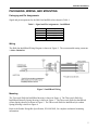
1
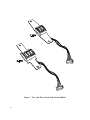
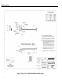
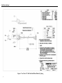
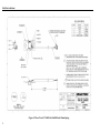
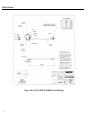
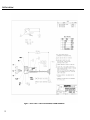
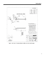
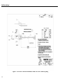
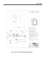
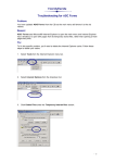
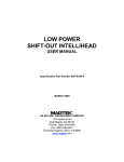
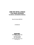
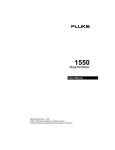
3V & 5V SHIFT-OUT INTELLIHEAD USER MANUAL Specification Part Number 99875258-10 APRIL 2014 AN ISO 9001 REGISTERED COMPANY 1710 Apollo Court Seal Beach, CA 90740 Phone: (562) 546-6400 FAX: (562) 546-6301 Technical Support: (651) 415-6800 www.magtek.com Copyright© 2001-2014 MagTek®, Inc. Printed in the United States of America Information in this document is subject to change without notice. No part of this document may be reproduced or transmitted in any form or by any means, electronic or mechanical, for any purpose, without the express written permission of MagTek, Inc. MagTek is a registered trademark of MagTek, Inc. MLF is a trademark of Amkor, Inc. REVISIONS ii Rev Number 1 2 Date 17 Mar 03 13 Jun 03 3 04 Oct 03 4 4 May 04 5 01 Aug 05 6 17 Apr 06 7 8 30 Aug 06 19 Jan 06 9 10 3 Jul 07 15 Apr 14 Notes Initial Release Front Matter: added ISO line to logo, changed Tech Support phone number. Editorial updates to match 99875259-5. Added clarification to handshake sequence. Reduced max operating voltage. Front Matter: Added Frontispiece drawing; Added new Figures 2 and 3. Configurations: Changed part numbers and descriptions of both entries. Removed bulk of spec while referencing ASIC spec. Added 21030012 & 21030013 to Sec 1, configuration list and to drawings in Packaging, Wiring, and Mounting. Converted to 3V Delta 3-track ASIC. Sec 1, Features: corrected Low voltage operation, Low operating current, and Ultra-low Sleep current. Added drawing, Figure 7, 21030019. Added 5V IntelliHead models: 21030021, -22, -27 & -28 Added reference to low power and 5V-to-3V models: 21030027& 21030028 Added 21030030; removed 21030019 Include latest drawings; further clarify meaning of Transition Revision in the Configurations table TABLE OF CONTENTS INTRODUCTION........................................................................................................................................... 1 FEATURES ................................................................................................................................................... 1 CONFIGURATIONS ...................................................................................................................................... 2 REFERENCE DOCUMENTS ........................................................................................................................ 2 SHIFT-OUT PROTOCOL .............................................................................................................................. 3 SHIFT-OUT TIMING ..................................................................................................................................... 3 TECHNICAL SPECIFICATIONS ................................................................................................................... 4 PACKAGING, WIRING, AND MOUNTING ................................................................................................... 5 Packaging and Pin Assignments .............................................................................................................. 5 Wiring ........................................................................................................................................................ 5 Mounting ................................................................................................................................................... 5 FIGURES & TABLES Figure 1. Two- and Three-Track Shift-Out IntelliHead .................................................................................iv Table 1. Signal and Pin Assignments – IntelliHead ..................................................................................... 5 Figure 2. IntelliHead Wiring ........................................................................................................................... 5 Figure 3. Three-Track 3V Shift-Out IntelliHead, Butterfly Spring .................................................................. 6 Figure 4. Two-Track 3V Shift-Out IntelliHead, Butterfly Spring .................................................................... 7 Figure 5. Three-Track 3V Shift-Out IntelliHead, 43mm Spring ..................................................................... 8 Figure 6. Three-Track 3V Shift-Out IntelliHead, Accordion Spring ............................................................... 9 Figure 7. Three-Track 3V Shift-Out IntelliHead, 4.05mm Beam Head ....................................................... 10 Figure 8. Three-Track 5V Shift-Out IntelliHead, 125mm, Wire 5PMLX, Butterfly Spring .......................... 11 Figure 9. Two-Track 5V Shift-Out IntelliHead, 125mm, Wire 5PMLX, Butterfly Spring ............................. 12 Figure 10. Three-Track 3V Shift-Out IntelliHead, 5.08mm Beam Head .................................................... 13 iii Figure 1. Two- and Three-Track Shift-Out IntelliHead iv INTRODUCTION MagTek’s Shift-Out IntelliHead consists of a high-performance multi-channel fully integrated magnetic stripe decoder chip encapsulated within a low-profile magnetic read-head. This innovative, yet low-cost card reading solution offers many important advantages over the conventional lessintegrated approach. The fully integrated Shift-Out IntelliHead is recommended for optimal performance; however, the Triple Track Delta ASIC (Application Specific Integrated Circuit) embedded in MagTek’s Shift-Out IntelliHead is available separately in a 14 pin MLFTM (MicroLeadFrameTM) package for those applications dictating the use of a particular separate magnetic head. Refer to MagTek specification 99875337 (for the 3V part) or 99875336 (for the old 5V unit). Two other variations on the Shift-Out IntelliHead are also offered: The Low-Power Shift-Out IntelliHead (21030028 & 21030036) is designed for battery operated devices that need to “wake from swipe.” It features a typical quiescent current when armed to accept a swipe of only 1.5 μA. See MagTek specification 99875349 for details. The 5V-to-3V Shift-Out IntelliHead (21030027) is designed to allow the customer to take advantage of some of the cost savings of the newer 3V Delta ASIC in most 5V systems. It features a built-in regulator that accepts a supply voltage of 5V ±5%. See MagTek specification 99875350 for details. FEATURES • Low cost solution for single, dual, or triple track readers – available in dual and triple-track models • Ultra-compact design – low-profile read head contains all needed circuits. Save PCB space! • No external components – even the decoupling capacitor is integrated. Only 4 signals, VDD, VSS, DATA, and STROBE to connect to your micro-controller for up to 3 tracks • Data buffer with Shift-Out – allows full card data to be locally stored on ASIC. Use a low-cost controller with no interrupts, limited memory, low-speed, low pin-count, etc. • High noise immunity – no analog signals leave the shielded magnetic head! Withstands noisy PC monitors, cell phones, switching power supplies, etc. • High performance decoding – new design reads badly damaged cards; compensates for poor head mounting • Low voltage operation – 2.7 V to 3.6 V (2.8 V to 5.5 V for 5V units)* • Low operating current – less than 1 mA maximum total current at 3.3V (for up to 3 tracks) while card is being swiped (less than 4 mA for 5V units)* • Ultra-low Sleep current – less than 120 μA maximum total current when no card is being swiped 1 IntelliHead • AGC (Automatic Gain Control) – reads cards from 30% - 200% of ISO 7811 amplitude standard • Simplified firmware – Shift-Out format makes it easier to write controller code • Wide operational temperature range – -40° C to +85° C • Wide range of card swipe speeds – from 3 ips to 100 ips (7 cm/s to 250 cm/s) * See CONFIGURATIONS section below for the definition of 5V unit. CONFIGURATIONS The Transition Revision column in the table below represents the first revision for which the 3V Delta ASIC (21006540/41) was used instead of the older 5V Delta ASIC. The 5V Delta ASIC (21006529/39 or 21006536/37) is detailed in 99875336 or 99875259. Part Number Transition Revision* Description 21030001 G IntelliHead 3V, 3 Track, butterfly spring, 125mm wire, 5-pin Molex connector 21030002 F IntelliHead 3V, 2 Track, butterfly spring, 125mm wire, 5-pin Molex connector 21030012 B IntelliHead 3V, 3 Track, 43mm spring, 125mm wire, 5-pin Molex connector 21030013 C IntelliHead 3V, 3 Track, Accordion spring, 125mm wire, 5-pin Molex connector 21030018 2 IntelliHead 3V, 3 Track, 4.05mm beam head, 125mm wire, 5-pin Molex connector 21030021 n/a** IntelliHead 5V, 3 Track, butterfly spring, 125mm wire, 5-pin Molex connector 21030022 n/a** IntelliHead 5V, 2 Track, butterfly spring, 125mm wire, 5-pin Molex connector 21030030 A IntelliHead 3V, 3 Track, 5.08mm beam head, 125mm wire, 5-pin Molex connector ** Not Applicable. This version will always use the 5V Delta ASIC and can be used if the application cannot use the 3V model. REFERENCE DOCUMENTS Magnetic Card Reader Design Kit Technical Specification, P/N 99821002 Triple Track ASIC With Shift-Out, 3V, Specifications, P/N 99875337 Triple Track ASIC With Shift-Out, 5V RoHS Compliant, Specifications, P/N 99875336 Triple Track ASIC With Shift-Out, 5V, Specifications, P/N 99875259 Low Power Shift-Out IntelliHead User Manual, P/N 99875349 5V-to-3V Shift-Out IntelliHead User Manual, P/N 99875350 2 Shift-Out IntelliHead SHIFT-OUT PROTOCOL Refer to MagTek specification 99875337 (99875336 or 99875259 for 5V units) for details of the ShiftOut Protocol. The additional information below is needed for the firmware designer to assign the memory-tracks of the ASIC (A, B, and C) to the physical magnetic head tracks (1, 2, and 3). The on-chip memory tracks of the Shift-Out IntelliHead are permanently assigned to particular tracks of the magnetic head via internal wires connecting the head coil wires to particular inputs of the builtin ASIC. Tracks ‘A’ and ‘B’ of the internal ASIC correspond to tracks ‘1/3’ and ‘2’ of the reader respectively as it is shown in Figure 2. When the 2-track IntelliHead/spring is mounted as intended, with the centerline of the spring mounting holes running through the center of track 2, it may be used as either a track 1 & 2 reader or a track 2 & 3 reader. Typically the dual-track IntelliHead serves as a track 1 & 2 reader. For the less common track 2 & 3 reader, this IntelliHead/spring assembly may be used in an inverted configuration on the same chassis used by a track 1 & 2 reader. In this case, onchip memory track ‘A’ corresponds to physical magnetic stripe track 3 and on-chip memory track ‘B’ corresponds to physical magnetic stripe track 2. This is important since it affects the arrangement of the data upon extraction from the chip (see below). Similar concerns apply for the triple-track Shift-Out IntelliHead. As it is oriented in tracks ‘A’, ‘B’, and ‘C’ of the internal ASIC correspond to tracks ‘1’, ‘2’, and ‘3’ of the reader respectively. The IntelliHead may be mounted with the opposite orientation if desired, but firmware must anticipate this re-mapping of ASIC memory tracks to physical magnetic head tracks. SHIFT-OUT TIMING Refer to MagTek specification 99875337 (99875336 or 99875259 for 5V units) for details of the ShiftOut Timing. The following exception exists for the IntelliHead in contrast to the ASIC specification given in 99875337. Trst (Reset) = 10 s minimum (not shown in timing diagram) VDD off-time to guarantee a reset for the ASIC/Head unit. This is due to an RC power supply filter inside the head. R = 10Ω 5% and C = 0.1 F + 80%, -20%. 3 IntelliHead TECHNICAL SPECIFICATIONS Technical Specifications are as follows: ELECTRICAL Electrical Details See MagTek Specification 99875337 (99875336 or 99875259 for 5V units) Electrostatic Discharge ± 15kV discharge to head-can with head-can grounded MECHANICAL Dimensions As shown in the Figures at the end of this document Life 1,000,000 Passes ENVIRONMENTAL Operating Environment Temperature Relative Humidity Storage Environment Temperature Relative Humidity 4 -40 oC to +85 oC (-40 oF to +185 oF) 10% to 90% non-condensing -40oC to +100 oC (-40 oF to +212 oF) 10% to 90% non-condensing Shift-Out IntelliHead PACKAGING, WIRING, AND MOUNTING Packaging and Pin Assignments Signal and pin assignments for the Shift-Out IntelliHead are shown in Table 1. Table 1. Signal and Pin Assignments – IntelliHead Pin Number 1 2 3 4 5 Description STROBE DATA VDD GND CASE Wiring The Shift-Out IntelliHead Wiring Diagram is shown in Figure 2. The recommended mating connector is Molex 53048-0510. Figure 2. IntelliHead Wiring Mounting The Two-track Shift-Out IntelliHead drawing is shown in Figure 4. The Three-track Shift-Out IntelliHead (Butterfly Spring) drawing is shown in Figure 3. The Three-track Shift-Out IntelliHead (43mm Spring) drawing is shown in Figure 5. The Three-track Shift-Out IntelliHead (Accordion Spring) drawing is shown in Figure 6. Refer to the Reader Design Kit Specification, P/N 99821002, for complete mechanical mounting information. 5 Shift-Out IntelliHead Figure 3. Three-Track 3V Shift-Out IntelliHead, Butterfly Spring 6 Shift-Out IntelliHead Figure 4. Two-Track 3V Shift-Out IntelliHead, Butterfly Spring 7 Shift-Out IntelliHead Figure 5. Three-Track 3V Shift-Out IntelliHead, 43mm Spring 8 Shift-Out IntelliHead Figure 6. Three-Track 3V Shift-Out IntelliHead, Accordion Spring 9 Shift-Out IntelliHead Figure 7. Three-Track 3V Shift-Out IntelliHead, 4.05mm Beam Head 10 Shift-Out IntelliHead Figure 8. Three-Track 5V Shift-Out IntelliHead, 125mm, Wire 5PMLX, Butterfly Spring 11 Shift-Out IntelliHead Figure 9. Two-Track 5V Shift-Out IntelliHead, 125mm, Wire 5PMLX, Butterfly Spring 12 Shift-Out IntelliHead Figure 10. Three-Track 3V Shift-Out IntelliHead, 5.08mm Beam Head 13