1
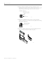
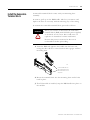
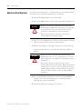
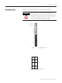
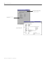
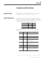
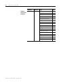
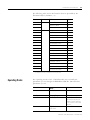
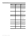
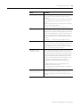
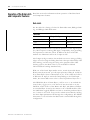
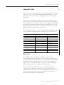
POINT I/O
Synchronous Serial
Interface Absolute
Encoder Module
1734-SSI
User Manual
Important User Information
Solid state equipment has operational characteristics differing from those of
electromechanical equipment. Safety Guidelines for the Application,
Installation and Maintenance of Solid State Controls (Publication SGI-1.1
available from your local Rockwell Automation sales office or online at
http://literature.rockwellautomation.com/) describes some important
differences between solid state equipment and hard-wired electromechanical
devices. Because of this difference, and also because of the wide variety of
uses for solid state equipment, all persons responsible for applying this
equipment must satisfy themselves that each intended application of this
equipment is acceptable.
In no event will Rockwell Automation, Inc. be responsible or liable for indirect
or consequential damages resulting from the use or application of this
equipment.
The examples and diagrams in this manual are included solely for illustrative
purposes. Because of the many variables and requirements associated with any
particular installation, Rockwell Automation, Inc. cannot assume responsibility
or liability for actual use based on the examples and diagrams.
No patent liability is assumed by Rockwell Automation, Inc. with respect to
use of information, circuits, equipment, or software described in this manual.
Reproduction of the contents of this manual, in whole or in part, without
written permission of Rockwell Automation, Inc., is prohibited.
Throughout this manual, when necessary, we use notes to make you aware of
safety considerations.
WARNING
IMPORTANT
ATTENTION
Identifies information about practices or circumstances
that can cause an explosion in a hazardous environment,
which may lead to personal injury or death, property
damage, or economic loss.
Identifies information that is critical for successful
application and understanding of the product.
Identifies information about practices or circumstances
that can lead to personal injury or death, property
damage, or economic loss. Attentions help you:
• identify a hazard
• avoid a hazard
• recognize the consequence
SHOCK HAZARD
Labels may be located on or inside the equipment (for
example, drive or motor) to alert people that dangerous
voltage may be present.
BURN HAZARD
Labels may be located on or inside the equipment (for
example, drive or motor) to alert people that surfaces may
be dangerous temperatures.
Allen-Bradley, ControlLogix, POINT I/O, POINTBus, RSLinx, RSLogix 5000, RS Networx, and RSNetworx for DeviceNet are
trademarks of Rockwell Automation, Inc.
Trademarks not belonging to Rockwell Automation are property of their respective companies.
Summary of Changes
This publication contains new and revised information not in the last
release.
New and Revised Information
See the table for a summary of the major changes in this manual.
Chapter
Change
Chapter 4 Set and Operate
Your Module
Updated section on operation of the Data Latch and
Comparator features.
Chapter 5 Diagnose Problems
Added a column on recommended actions in all of the
troubleshooting charts.
Appendix A Configure Modules
in RSLogix 5000
Software
Updated procedures on how to use the Watch Position
dialog.
Change Bars
We marked with change bars (as shown with this paragraph) the areas
in this manual that are different from previous editions and indicate
the addition of new or revised information.
1
Publication 1734-UM007D-EN-P - December 2005
Summary of Changes
2
Notes:
Publication 1734-UM007D-EN-P - December 2005
Table of Contents
Preface
Purpose of This Manual. . . . . . . . . . . . . . . . . . . . . . . Preface-1
Who Should Use This Manual . . . . . . . . . . . . . . . . . . Preface-1
Related Products and Documentation. . . . . . . . . . . . . Preface-2
Chapter 1
Install the Module
About This Chapter . . . . . . . . . . . . . .
About the Module . . . . . . . . . . . . . . .
Install the Mounting Base . . . . . . . . .
Install a Module . . . . . . . . . . . . . . . .
Install the Removable Terminal Block
Remove a Mounting Base . . . . . . . . .
Wire the Module . . . . . . . . . . . . . . . .
.
.
.
.
.
.
.
.
.
.
.
.
.
.
.
.
.
.
.
.
.
.
.
.
.
.
.
.
.
.
.
.
.
.
.
.
.
.
.
.
.
.
.
.
.
.
.
.
.
.
.
.
.
.
.
.
.
.
.
.
.
.
.
.
.
.
.
.
.
.
.
.
.
.
.
.
.
.
.
.
.
.
.
.
.
.
.
.
.
.
.
.
.
.
.
.
.
.
.
.
.
.
.
.
.
.
.
.
.
.
.
.
1-1
1-1
1-2
1-3
1-5
1-6
1-7
About This Chapter . . . . . . . . . . . . . . . .
Add the Adapter to Your Network . . . . .
Add I/O Modules to Your Network . . . .
Set the Encoder’s Parameters . . . . . . . . .
Check I/O Status and View the EDS File
.
.
.
.
.
.
.
.
.
.
.
.
.
.
.
.
.
.
.
.
.
.
.
.
.
.
.
.
.
.
.
.
.
.
.
.
.
.
.
.
.
.
.
.
.
.
.
.
.
.
.
.
.
.
.
.
.
.
.
.
.
.
.
.
.
.
.
.
.
.
2-1
2-1
2-2
2-3
2-5
.
.
.
.
.
.
.
.
.
.
.
.
.
.
.
.
.
.
.
.
.
.
.
.
.
.
.
.
.
.
.
.
.
.
.
.
.
.
.
.
.
.
.
.
.
.
.
.
.
.
.
.
.
.
.
.
3-1
3-1
3-3
3-5
About This Chapter . . . . . . . . . . . . . . . . . . . . . . . . . .
Module Configuration Value Definitions. . . . . . . . . . .
Operation of the Data Latch and Comparator Features
Data Latch . . . . . . . . . . . . . . . . . . . . . . . . . . . . . .
Comparators 1 and 2 . . . . . . . . . . . . . . . . . . . . . .
Other Module Features . . . . . . . . . . . . . . . . . . . . . . .
Example of Using the 1734-SSI Module
with a 24-bit SSI Sensor . . . . . . . . . . . . . . . . . . . . . . .
.
.
.
.
.
.
.
.
.
.
.
.
.
.
.
.
.
.
.
.
.
.
.
.
4-1
4-1
4-4
4-4
4-5
4-6
Chapter 2
Configure the Module
Chapter 3
Communicate with Your Module
About This Chapter . . . . . . . . . . . . .
About Communications . . . . . . . . . .
Communicate Real-time Information
Operating Modes . . . . . . . . . . . . . .
.
.
.
.
.
.
.
.
.
.
.
.
Chapter 4
Set and Operate Your Module
. . . . 4-7
Chapter 5
Diagnose Problems
1
About This Chapter . . . . . . . . . . . . . . . . . . . . . . . . . . . . . . 5-1
Use the Indicators for Troubleshooting . . . . . . . . . . . . . . . 5-1
Publication 1734-UM007D-EN-P - December 2005
Table of Contents
2
Appendix A
Configure Modules in RSLogix
5000 Software
Index
Publication 1734-UM007D-EN-P - December 2005
About This Appendix . . . . . . . . . . . . . . . . . . . . . . . . . . . .
Understand Data, Connection, and Communication Formats
Configure Your Module. . . . . . . . . . . . . . . . . . . . . . . . . . .
Use the Help Button . . . . . . . . . . . . . . . . . . . . . . . . . . . . .
Work with the Feedback Dialog . . . . . . . . . . . . . . . . . . . .
Work with the Conversion Dialog . . . . . . . . . . . . . . . . . . .
Work with the Input Registration Dialog . . . . . . . . . . . . . .
Work with the Watch Position Dialog . . . . . . . . . . . . . . . .
A-1
A-1
A-2
A-2
A-3
A-4
A-6
A-7
Preface
Purpose of This Manual
Who Should Use This
Manual
Read this manual for information about how to install, configure, and
troubleshoot your module.
For This Information
See
Install the Module
Chapter 1
Configure the Module
Chapter 2
Communicate with Your Module
Chapter 3
Operate Your Module
Chapter 4
Diagnose Problems
Chapter 5
Configure Modules in RSLogix 5000
Appendix A
You must be able to use RSNetWorx software or similar configuration
software to set up and calibrate these modules. You must have the
capability to download and use electronic data sheet files.
In this manual, we assume you know how to do perform these tasks.
If you do not, refer to your software user manuals or online help
before attempting to use these modules.
1
Publication 1734-UM007D-EN-P - December 2005
2
Preface
Related Products and
Documentation
For specification, safety approval, and other information, refer to
POINT I/O Synchronous Serial Interface Absolute Encoder Module
Installation Instructions, publication 1734-IN581.
For related 1734 products and documentation, see the table. Many of
these publications are available online from
http://literature.rockwellautomation.com
Publication 1734-UM007D-EN-P - December 2005
Description
Cat. No.
Publication
Analog Input Modules
Installation Instructions
1734-IE2C
17340IE2V
1734-IN027
Analog Output Modules
Installation Instructions
1734-OE2C
1734-OE2V
1734-IN002
DeviceNet Communication Interface
Installation Instructions
1734-PDN
1734-IN057
Field Potential Distributor
Installation Instructions
1734-FPD
1734-IN059
POINT I/O 24V dc Expansion Power Supply
Installation Instructions
1734-EP24DC
1734-IN058
POINT I/O Selection Guide
1734 series
1734-SG001
Protected Output Module s
Installation Instructions
1734-OB2E
1734-OB4E
1734-OB8E
1734-IN056
Relay Output Modules
Installation Instructions
1734-OW2
1734-OW4
1734-IN055
Sink Input Modules
Installation Instructions
1734-IB2
1734-IB4
1734-IB8
1734-IN051
Source Output Modules
Installation Instructions
1734-IV2
1734-IV4
1734-IV8
1734-IN052
Very High-speed Counter Modules
Installation Instructions
1734-VHSC5
1734-VHSC24
1734-IN003
Wiring Base Assembly
Installation Instructions
1734-TB
1734-TBS
1734-IN511
Wiring Base Assembly
Installation Instructions
1734-TB3
1734-TB3S
1734-IN013
Chapter
1
Install the Module
About This Chapter
Read this chapter to learn about how to install, wire, and remove the
1734-SSI module.
About the Module
The 1734-SSI module collects serial data from industrial
absolute-position encoding sensors that use a standard SSI protocol.
Slide-in Writable Label
2
S 4V
O ou DC
ut rc
pu e
t
M
St od
at u
us le
N
St etw
N a
O tu o
D s rk
E:
1
3
1
O 73
B 4
4E
2
1
0
Module Locking Mechanism
Insertable I/O Module
Module Wiring Diagram
Mechanical Keying
RTB Removing Handle
(Orange)
DIN Rail Locking Screw
(Orange)
Removable Terminal Block (RTB)
Interlocking Side Pieces
43122
Mounting Base
Insert the module into a POINT I/O terminal base that provides
common power, communication, and wiring connections for the SSI
sensors. Use this Series C module with the following.
• ControlNet adapter
with RSLogix 5000 software, version 11 or later
• DeviceNet adapter
• EtherNet/IP adapter
with RSLogix 5000 software, version 11 or later
• PROFIBUS adapter
1
Publication 1734-UM007D-EN-P - December 2005
1-2
Install the Module
Install the Mounting Base
The wiring base assembly (1734-TB or 1734-TBS) consists of a
mounting base (1734-MB) and a removable terminal block (1734-RTB
or 1734-RTBS). You can install the assembly, or just the mounting
base. To install the mounting base/wiring base assembly on the DIN
rail, proceed as follows.
ATTENTION
POINT I/O is grounded through the DIN rail to
chassis ground. Use zinc-plated yellow-chromate
steel DIN rail to assure proper grounding. The use of
other DIN rail material (such as aluminum and
plastic) that can corrode, oxidize, or are poor
conductors, can result in improper or intermittent
grounding.
Secure DIN rail to mounting surface approximately
every 200 mm (7.8 in.).
1. Position the mounting base/wiring base assembly vertically
above the installed units (adapter, power supply, or existing
module).
2. Slide the mounting base down, allowing the interlocking side
pieces to engage the adjacent module or adapter.
Slide the mounting base to allow the
interlocking side pieces to engage the
adjacent module or adapter.
31586
Publication 1734-UM007D-EN-P - December 2005
Install the Module
1-3
3. Press firmly to seat the mounting base on the DIN rail, noting
that the mounting base snaps into place.
M
Stod
ule
atus
Ne
Stattwor
us k
NO
DE
:
0
24
So VDC
Ouurce
tput
1
2
3
17
OB34
4E
44013
4. To remove the mounting base from the DIN rail, remove any
installed module (and any module immediately to the right), and
use a small-bladed screwdriver to rotate the DIN rail locking
screw to a vertical position.
This releases the locking mechanism.
5. Lift straight up to remove the mounting base.
6. Repeat this procedure for the next mounting base assembly.
Install a Module
Install the module before or after base installation. Make sure that the
mounting base is correctly keyed before installing the module into the
mounting base. In addition, make sure the mounting base locking
screw is horizontal referenced to the base.
WARNING
When you insert or remove the module while
backplane power is on, an electrical arc can occur.
This could cause an explosion in hazardous location
installations.
Be sure that power is removed or the area is
nonhazardous before proceeding. Repeated electrical
arcing causes excessive wear to contacts on both the
module and its mating connector. Worn contacts may
create electrical resistance that can affect module
operation.
Publication 1734-UM007D-EN-P - December 2005
1-4
Install the Module
1. Using a bladed screwdriver, rotate the keyswitch on the
mounting base clockwise till the number required for the type of
module being installed aligns with the notch in the base.
1734-SSI - Position 2
Turn the keyswitch to align
the number with the notch.
Notch
(Position 3 Shown)
44009
2. Make sure the DIN-rail locking screw is in the horizontal
position, noting that you cannot insert the module if the locking
mechanism is unlocked.
Make sure the DIN-rail
locking screw is in the
horizontal position.
44101
M
St od
at u
us le
3
1
O 73
B 4
4E
2
1
0
2
S 4V
O ou DC
ut rc
pu e
t
N
N
S et
t w
O atu o
D s rk
E:
3. Insert the module straight down into the mounting base and
press to secure, locking the module into place.
44012
Publication 1734-UM007D-EN-P - December 2005
Install the Module
Install the Removable
Terminal Block
1-5
A removable terminal block comes with your mounting base
assembly.
To remove, pull up on the RTB handle. This lets you remove and
replace the base as necessary without removing any of the wiring.
To reinsert the removable terminal block, proceed as follows.
WARNING
When you connect or disconnect the removable
terminal block (RTB) with field-side power applied,
an electrical arc can occur. This could cause an
explosion in hazardous location installations.
Be sure that power is removed or the area is
nonhazardous before proceeding.
1. Insert the RTB end opposite the handle into the base unit,
noting that the end has a curved section that engages with the
mounting base.
44011
Hook the RTB end into
the mounting base end,
and rotate until it locks
into place.
2. Rotate the terminal block into the mounting base until it locks
itself in place.
3. If an I/O module is installed, snap the RTB handle into place on
the module.
Publication 1734-UM007D-EN-P - December 2005
1-6
Install the Module
Remove a Mounting Base
To remove a mounting base, you must remove any installed module,
and remove the removable terminal block (if wired).
1. Unlatch the RTB handle on the I/O module.
2. Pull on the RTB handle to remove the removable terminal block.
WARNING
When you connect or disconnect the removable
terminal block (RTB) with field-side power applied,
an electrical arc can occur. This could cause an
explosion in hazardous location installations.
Be sure that power is removed or the area is
nonhazardous before proceeding.
3. Press in on the module lock on the top of the module, and pull
up on the I/O module to remove from the base.
4. Remove the module to the right of the base you are removing.
The interlocking portion of the base sits under the adjacent
module.
WARNING
When you insert or remove the module while
backplane power is on, an electrical arc can occur.
This could cause an explosion in hazardous location
installations.
Be sure that power is removed or the area is
nonhazardous before proceeding. Repeated electrical
arcing causes excessive wear to contacts on both the
module and its mating connector. Worn contacts may
create electrical resistance that can affect module
operation.
5. Use a small-bladed screwdriver to rotate the orange DIN-rail
locking screw on the mounting base to a vertical position,
releasing the locking mechanism.
6. Lift the mounting base straight up to remove.
Publication 1734-UM007D-EN-P - December 2005
Install the Module
Wire the Module
1-7
Read this section for information about wiring the module.
WARNING
If you connect or disconnect wiring while the
field-side power is on, an electrical arc can occur.
This could cause an explosion in hazardous location
installations. Be sure that power is removed or the
area is nonhazardous before proceeding.
Module Status
Network Status
Module
Status
Network
Status
NODE:
RUN
Run
Up
Down
Comp
I1
UP
DOWN
COMP
I1
1734
SSI
D+
D-
V+
V-
Shield
I1
C+
C-
D = Data
C = Clock
I1 = Digital Sourcing Input 1
V = SSI Sensor
1
0
D+
2
D3
V+
4
V5
I1
Shield
6
43123
C+
7
C43124
D = Data
C = Clock
I1 = Digital Sourcing Input 1
V = SSI Sensor
Publication 1734-UM007D-EN-P - December 2005
1-8
Install the Module
Module Terminations
0
D+1
1
D-1
2
V+
3
V-
4
Shield
5
I1
6
C+1
7
C-1
1
Publication 1734-UM007D-EN-P - December 2005
D and C are RS422-type
differential pairs.
Chapter
2
Configure the Module
About This Chapter
Read this chapter for information about how to use RSNetWorx for
DeviceNet software to configure your module. You can configure the
module while it is online or offline.
This chapter shows configuration in the online mode. Configuration
dialogs appear similar in both modes. The primary difference is that if
you make changes offline, you must go online before the
configuration changes take effect.
Add the Adapter to Your
Network
To add the adapter to your network, follow these steps.
1. Start the RSNetWorx for DeviceNet software.
2. Add the communication device as shown, noting that in this
case, the chosen device was a 1734-ADN DeviceNet adapter.
1. Click here to expand the list
of communication adapters.
2. Double-click the 1734-ADN
DeviceNet adapter. (You can
also click and drag the
adapter name onto the
network.)
1
The scanner appears
on the network.
Publication 1734-UM007D-EN-P - December 2005
2-2
Configure the Module
Add I/O Modules to Your
Network
After you add the communication device, you must add the POINT
I/O modules connected to the scanner on the POINTBus backplane,
using this procedure.
1. Add modules as shown in the figure.
1. Click here to expand the list
of specialty modules.
2. Double-click the catalog
number to choose the
module. You can also click
and drag the module name
onto the network.
The out-of-the-box node setting for 1734 modules is 63. You can
change the setting by using the node commissioning tool. The
node commissioning tool is available either online or offline.
IMPORTANT
If you commission a node online, you must power
down your system before the change takes place.
2. Double-click the module to change the node address.
Publication 1734-UM007D-EN-P - December 2005
Configure the Module
Set the Encoder’s
Parameters
2-3
After adding the module to the network, you must configure the
module for use.
IMPORTANT
This chapter shows configuration in the online
mode. Changes set in this mode take effect when
you download to the individual module.
1. Configure the modules as shown in the figure.
1. Click the module to
highlight it.
2. From the Device menu,
choose Properties.
You can also right-click the module or name,
and the property dialog pops up.
You see a dialog with a series of tabs. Each tab provides options
to view or edit.
These are the tabs you click to
view the options.
Publication 1734-UM007D-EN-P - December 2005
2-4
Configure the Module
2. Refer to the dialogs for an explanation of features.
The module’s name appears
here.
Click the Device parameters tab to
get to the dialog for setting the
parameters.
Type a description here.
The module’s address appears
here. (This field is read only.)
This dialog also shows the
module’s device identity.
These fields are read only.
At any point, you can click here to finish
changing configuration parameters.
If configuration changes are made in offline
mode, they do not take effect until the
system goes online.
This dialog appears after you click
the Device parameters tab. If you
want the existing parameters
uploaded from the module, click
Upload. The following dialog then
shows the existing parameters set
on the module.
Use this menu to edit or view
the parameters. Available
choices are:
Configuration
Publication 1734-UM007D-EN-P - December 2005
Configure the Module
2-5
To configure your module,
select Configuration and
modify the parameters as
desired for your application.
When complete, download to
your module by clicking the
Download to Device button.
You can download each
change as you make it using
Single, or download all your
changes using All.
Click here when finished.
Check I/O Status and View
the EDS File
You can view the I/O defaults setup, and the EDS file by clicking the
appropriate tab.
Click the I/O Data tab to display the
default characteristics for this module.
This dialog shows the input/output defaults
for the four modes. These are:
Strobe
Polled
Change of state
Cyclic
Publication 1734-UM007D-EN-P - December 2005
2-6
Configure the Module
Click the EDS File tab to display
the statistics of the EDS file used
to configure this module.
Click View File to view the
actual EDS file.
You can view the actual
EDS file or edit the file.
Publication 1734-UM007D-EN-P - December 2005
Chapter
3
Communicate with Your Module
About This Chapter
Read this chapter for information about how the 1734-SSI module
transmits SSI sensor data over the DeviceNet network.
About Communications
Data can be exchanged with the master through a polled, cyclic, or
change-of-state connection. Bit-strobe Command Response Messaging
and the Unconnected Message Manager (UCMM) are not supported.(1)
The module produces and consumes data as follows:
I/O Connection Type Consumes
Produces
Polled
2 bytes
10 bytes
Cyclic
2 bytes
10 bytes
Change-of-state
2 bytes
10 bytes
See the following tables for consume and produced bit and byte
definitions.
(1)
1
Byte
Bit
Description
Produce 0
0…7
Low byte of present low SSI word. Bit 0
is the least significant bit of the entire
present SSI word.
Produce 1
0…7
High byte of present low SSI word.
Produce 2
0…7
Low byte of present high SSI word.
Produce 3
0…7
High byte of present high SSI word. Bit 7
is the most significant bit of the entire
present SSI word.
Produce 4
0…7
Low byte of latched low SSI word. Bit 0
is the least significant bit of the entire
latched SSI word.
Produce 5
0…7
High byte of latched low SSI word.
Produce 6
0…7
Low byte of latched high SSI word.
Produce 7
0…7
High byte of latched high SSI word. Bit 7
is the most significant bit of the entire
latched SSI word.
If you are not familiar with these terms, see the DeviceNet Specification for definitions (online: www.odva.org).
Publication 1734-UM007D-EN-P - December 2005
3-2
Communicate with Your Module
Byte
Produce 8
Produce 9
1
Bit
7
6
5
4
3
2
1
C2ST C1ST C2R
C1R
INC
DEC
RUN I1
7
6
5
4
3
2
1
0
RES
RES
RES
LHON
IDF2
CCE
CCF
SPF
Consume 0
Consume 1
Publication 1734-UM007D-EN-P - December 2005
0
Status Byte 0
Status Byte 11
Monitor IDF to determine the validity of the produced data. If IDF=1, the SSI data is false.
Byte
2
Description
Bit
7
6
5
4
RES
RES
RES
7
6
RES
RES
3
Description
2
1
0
SCMP2 SCMP1 CC2
CC1
LACK
5
4
3
2
1
0
RES
RES
RES
RES
RES
RES
Master ACK
Byte2
CONS1
The master must provide the Master ACK Byte in order to receive the polled Produced bytes 0…9.
I1 = Input 1 Status (1 = Input 1 ON, 0 = OFF)
RUN = SSI Clock Output Status (1 = Clock Output ON, 0 = OFF)
DEC = SSI Data Count Decreasing (1 = Decreasing, 0 = Not Decreasing)
INC = SSI Data Count Increasing (1 = Increasing, 0 = Not Increasing)
C1R = Comparator 1 Value Reached (1 = Value Reached, 0 = Not Reached)
C2R = Comparator 2 Value Reached (1 = Value Reached, 0 = Not Reached)
C1ST = Comparator 1 Active (1 = Active, 0 = Not Active)
C2ST = Comparator 2 Active (1 = Active, 0 = Not Active)
SPF = SSI Sensor Power Fault (1 = Fault Present, 0 = No Fault)
CCF = Coprocessor Configuration Fault (1 = Fault Present, 0 = No Fault)
CCE = Coprocessor Communication Error (1 = Error Present, 0 = No Error)
IDF = SSI Input Data Fault (1 = Fault Present, 0 = No Fault)
LACK = Input 1 Latch Acknowledge (1 = Unlatch, 0 = No Fault)
CC1 = Clear Comparator 1 (1 = Clear)
CC2 = Clear Comparator 2 (1 = Clear)
SCMP1 = Set Comparator 1 (1 = Comparator 1 is Active)
SCMP2 = Set Comparator 2 (1 = Comparator 2 is Active)
RES = Reserved (Bit = 0)
LHON = Latched Data is Stored (1 = Latched Data Present, 0 = Latched Data Not Present)
Communicate with Your Module
Communicate Real-time
Information
3-3
The Synchronous Serial Interface Absolute Encoder module uses data
bytes composed into assemblies to communicate real-time input and
output data over an I/O connection, as well as non-real-time module
information by using an Explicit Messaging connection.
• Assembly 101 is produced data sent by the module over an I/O
or Explicit Messaging connection.
• Assembly 102 is consumed data that is received by the module
over an I/O or Explicit Messaging connection.
• Assembly 103 is configuration data that can be read or changed
over an Explicit Messaging connection.
The following table shows the 1734-SSI module data assemblies.
Instances
Services
Field
Bytes
#101 (0x65)
Get
Present SSI Data
4
Stored SSI Data
4
Module Status
2
Master Ack Byte
1
CONS1
1
Run
1
Gray/Binary
1
SSI Word Length
1
Data Rate
1
Gray to Binary Conversion
1
Standardization
1
SSI Word Delay Time
2
Trailing Bits
1
Latch Input Control
1
Sensor Resolution
2
Sensor Cycles
2
Alignment Byte (0x00)
2
Comparator 1 Value
4
Comparator 2 Value
4
Comp 1 Control
1
Comp 2 Control
1
#102 (0x66)
Firmware
Version 3.001
Only
#103 (0x67)
Set/Get
Set/Get
Publication 1734-UM007D-EN-P - December 2005
3-4
Communicate with Your Module
Firmware
Version 4.001
and above
Publication 1734-UM007D-EN-P - December 2005
Instances
Services
Field
Bytes
#123 (0x7B)
Set/Get
Run
1
Gray/Binary
1
SSI Word Length
1
Data Rate
1
Gray to Binary Conversion
1
Standardization
1
SSI Word Delay Time
2
Trailing Bits
1
Latch Input Control
1
Sensor Resolution
2
Sensor Cycles
2
SSI Word Filter Control
1
Alignment Byte (0x00)
1
Comparator 1 Value
4
Comparator 2 Value
4
Comp 1 Control
1
Comp 2 Control
1
Communicate with Your Module
3-5
The following table shows the Instance Services provided by the
Parameter Object (Attribute = 1).
Parameter
Services
Field
Bytes
1
Get
Present SSI Word
4
2
Latched SSI Word
4
3
SSI Status Word
2
Run
1
5
Gray/Binary
1
6
SSI Word Length
1
7
Data Rate
1
8
Gray to Binary Conversion
1
9
SSI Word Delay Time
2
10
Standardization
1
11
Trailing Bits
1
12
Latch Input Control
1
13
Sensor Resolution
2
14
Sensor Cycles
2
15
Comp 1 Control
1
16
Comparator 1 Value
4
17
Comp 2 Control
1
18
Comparator 2 Value
4
Get/Set
19
(1)
Operating Modes
SSI Word Filter Control
4
(1)
1
This parameter is present in firmware version 4.001 and later.
The operating modes of the 1734-SSI module are essentially the
parameters you set through the RSNetWorx EDS file. This table lists
parameters you set.
Parameter
Value(1)
Notes
Run
Enable/Disable
Turns SSI data clock on or
off
Data Type
Binary or Gray
SSI sensor’s data type
Data Word Length
2…31 (13)
Length of the received serial
data word can be any size
between 2 and 31 data bits.
Bit 32 is used for Latch Input
detection.
Data Rate
125/250/500K baud,
1/2M baud
Speed of SSI data clock
Publication 1734-UM007D-EN-P - December 2005
3-6
Communicate with Your Module
Parameter
Value(1)
Notes
Gray to Binary Conversion
No/Yes
Convert data from Gray to
binary
SSI Word Delay Time (tm)
16µs… to 64ms (64µs)
Delay time between
successive SSI data words
SSI Word Filter Control
Off, Low, Med, High, Max
Corresponds to the number
of successive equal SSI data
words that must be received
by the module in order to
update the real-time present
SSI data word.
Standardization
Off/On
Off = Use entire data word
length specified by Data
Word Length parameter.
On = Data is right-shifted
the number of bits specified
in the Trailing Bits
parameter.
Trailing Bits
0… 16
Sensor Resolution
1… 65535
Total number of
positions/revolution for a
rotary encoder,
positions/stroke for a linear
displacement transducer, or
maximum counts for
distance measurement.
Sensor Cycles
1… 65535
Total number of revolutions
for a rotary encoder, strokes
for a linear displacement
transducer
Latch Input
Off, Rising Edge, Falling
Edge, Both Edges
Master unlatches data by
transmitting the LACK bit
over the network
Comparator 1
Not Active, Up Direction,
Down Direction, Both
Directions
Module compares data to
value from the master. Only
one Compare value can be
active.
Comparator 2
Not Active, Up Direction,
Down Direction, Both
Directions
Module compares data to
value from the master. Only
one Compare value can be
active.
(1)
Publication 1734-UM007D-EN-P - December 2005
Default values are in bold.
Chapter
4
Set and Operate Your Module
About This Chapter
Read this chapter for information about setup and operation of your
module.
You need to alter the 1734-SSI module configuration, special data
latch feature, and comparator feature in order for the 1734-SSI module
to operate properly with your SSI sensor.
To quickly configure the 1734-SSI module for use with your SSI
sensor, change only the following values if they are different from the
module default values:
•
•
•
•
Module Configuration
Value Definitions
1
Data type
SSI word length
Data rate
SSI word delay
Value
Definition
RUN
The SSI clock output to the SSI sensor can be turned ON or
OFF by changing the RUN setting. You may find this feature
useful during machine setup or maintenance. The default
setting for RUN is ON. When you first apply power to the
module, the SSI clock output is active. The green LED on the
front of the module indicates the RUN status, as well as Bit
1 or Byte 0 in the module status word (produced byte 8, Bit
1; 1 = RUN ON, 0 = RUN OFF).
Data Type
This refers to the code type of your SSI sensor. The
1734-SSI module supports Gray and Binary code types.
The module default is Gray.
You must have the right code type selected so that other
module features operate correctly.
SSI Word Length
The number of bits in a single SSI word is completely
determined by the SSI sensor.
See the manufacturer’s data sheet for the sensor output
word size. The word length setting range is 2…31 bits. The
default SSI word length is 13 bits.
Publication 1734-UM007D-EN-P - December 2005
4-2
Set and Operate Your Module
Publication 1734-UM007D-EN-P - December 2005
Value
Definition
Data Rate
The data rate is the SSI sensor’s communication rate
(bits/s) stated in the manufacturer’s data sheet.
The data rate you select at the SSI module equals the
approximate frequency of the SSI module’s clock output
(the actual measure frequency varies with the SSI word
delay time).
The maximum data rate that can be used for your
application is limited by the transmission line length
between the SSI module and sensor.
See the SSI sensor data sheet, as well as the 1734-SSI
Installation Instructions, publication 1734-IN581, for
communication rate versus transmission line length
information. The module supports the following SSI data
rates: 125, 250, 500 Kbps, 1 and 2 MBps.
The module default rate is 125 Kbps.
Gray-to-Binary Conversion
The 1734-SSI module can change the displayed SSI sensor
data from Gray to Binary. Change this setting to ON only
when using a Gray-code sensor and you wish to read a
present SSI value that is proportional to total sensor travel.
Gray-code sensor values continuously increase and
decrease as the sensor travels in one direction, and do not
provide a sense of proportionality. The module default for
this setting is OFF.
SSI Word Delay Time
This is the time between successive SSI words that are
transmitted by the SSI sensor to the module. The 1734-SSI
module features a wide selection of delay times ranging
from 16…64,535 µs. The module default delay time is
64 µs. Refer to your SSI sensor data sheet for the
recommended delay time. If the sensor manufacturer
specifies a value called monoflop time, use that value for
the SSI word delay time setting.
SSI Word Filter Control
The number of successive, equal SSI data words received
by the module from the SSI sensor in order to update the
real-time present SSI data word. Max = 5 successive equal
values, High = 4, Med = 3, Low = 2, and Off = the module
produces a SSI data word each time a new value is
available from the SSI sensor, without the previous value
comparison. Adjust the SSI Word Filter Control value when
using SSI sensors with the Position Forming time
< 0.5 ms, so that you can see SSI sensor data change as the
sensor is in motion.
Note that changing the default value of 5 (Max) for this
parameter is done at the expense of reporting accurate
sensor data in an electrically noisy environment.
Data Standardization
You can remove bits from the right side of the displayed SSI
present value word by setting Data Standardization to ON.
This feature can be used as a divide by a power of two, or
for data masking. Enter the number of bits you wish to
remove in the Trailing Bits parameter (discussed below).
The default setting for Data Standardization is OFF.
Trailing Bits
The number of bits removed from the displayed SSI present
value word if Data Standardization is ON. The range is
0…16 bits, and the default value is 0.
Set and Operate Your Module
4-3
Value
Definition
Sensor Resolution
The number of steps per revolution for a rotary sensor, or
total number of steps per stroke for a linear or optical
transducer.
The Sensor Resolution value is not used by the module and
is not needed for proper module operation with your SSI
sensor.
The Sensor Resolution value can be passed to the network
master for processing if desired.
The range is 1…65,535 steps and the default value is 1.
Sensor Cycles
The total number of revolutions for a rotary sensor. If you
are using a linear or optical transducer, the value you should
enter for Sensor Cycles is most likely equal to one. Like the
Sensor Resolution parameter, the Sensor Cycle value is not
used by the module and is not needed for proper module
operation with your SSI sensor. Pass the value to the master
if needed.
The range is 1…65,535 steps and the default value is 1.
Data Latch
Define an edge of the sourcing I1 input for storing a sensor
position. The choices are the falling edge of I1 (Off-to-ON),
rising edge (On-to-OFF), or both falling edge and rising
edge. The default value for Data Latch is OFF. For operation
details, see operating feature of Data Latch.
Comparator 1 and
Comparator 2 Control
You can compare the incoming SSI sensor count to a stored
value, and the module provides notification of the event
when the present sensor value equals or exceeds the stored
value. The module stores two separate comparator values
(1 and 2), governed by separate comparator control values
(1 and 2). Using the comparator control parameter, you can
set the module to flag the event on an increasing,
decreasing, or both (increasing and decreasing) sensor
count.
The default setting for both of the Comparator 1 and
Comparator 2 Control values is OFF.
For operation details, see operating features of Comparator
1 and Comparator 2 Control.
Comparator 1 and
Comparator 2 Value
Enter your comparator value into these parameters.
Comparator values can be obtained by moving your SSI
sensor to the position of interest and reading the present
SSI value.
Publication 1734-UM007D-EN-P - December 2005
4-4
Set and Operate Your Module
Operation of the Data Latch
and Comparator Features
Read this section for information about operation of the Data Latch
and Comparator features.
Data Latch
See the table for a listing of values for DeviceNet name, RSLogix 5000
tag, and RSLogix 5000 field name.
Data Latch
DeviceNet Name
RSLogix 5000 Tag
RSLogix 5000 Field Name
Bit 0 of Status Byte 0
Input
InputStatus
LHON:
Input
DataLatched
LACK
Output
LatchAck
SSI sensor positions can be stored with operation of the digital input
(I1). The I1 input is sourcing (IEC Type 3 compatible); thus grounding
the input turns it ON. The yellow I1 LED on the front of the SSI
module also illuminates when the I1 input is ON.
The I1 input is edge-sensitive: the module can react to rising or falling
edges of I1. Choosing the falling data latch value provides OFF-to-ON
data latching, and choosing the rising value provides ON-to-OFF
latching. Choose the Both value if you need OFF-to-ON and
ON-to-OFF data latching simultaneously.
With one of the Latch Input modes active, watch the module Status
Word (status bytes 0 and 1) for I1 input operation. When I1 is ON, bit
I1 in Status Byte 0 (bit 0 of Status Byte 0) is 1. If I1 is OFF, the I1 bit is
0. When the I1 input is activated corresponding to the Latch Input
mode, the current SSI sensor value is stored in produced bytes 4 to 7.
The LHON bit (bit 4 of Status Byte 1) will be set to 1. To unlatch the
stored value, toggle (set to 1 for about 0.5 ms, then back to 0) the
LACK bit, which is bit 0 of the Master Ack Byte. The Master Ack Byte
is consumed Byte 0 sent by the master to the 1734-SSI module. Once
the LACK bit is toggled, LHON is set back to 0 and the produced bytes
4 to 7 return to 0 as well. You can also unlatch stored data by turning
the Latch Input parameter OFF through the configuration. The LHON
bit returns to 0 as well when the Data Latch is turned OFF through the
configuration.
Publication 1734-UM007D-EN-P - December 2005
Set and Operate Your Module
4-5
Comparators 1 and 2
You can store two separate four-byte values and be notified when the
SSI sensor attains or exceeds the stored value. Comparators 1 and 2
are mutually exclusive: only one comparator can be active at any
given time.
You can set a comparator to trigger on an increasing sensor count,
decreasing count, or regardless of sensor direction, by choosing Both
for the comparator control value. There are two modes of comparator
operation: manual and automatic. The green COMP LED on the front
of the module illuminates when a comparator value is reached. The
LED goes OFF when comparator reset occurs.
See the table for a listing of values for DeviceNet name, RSLogix 5000
tag, and RSLogix 5000 field name for Manual and Automatic mode.
Manual and Automatic Mode
DeviceNet Name
RSLogix 5000 Tag
RSLogix 5000 Field Name
C1ST
Input
Compare0Status
C2ST
Input
Compare1Status
CC1
Output
Compare0Ack
CC2
Output
Compare1Ack
C1R
Input
Compare0Reached
C2R
Input
Compare1Reach
SCMP1
Output
Compare0Select
SCMP2
Output
Compare1Select
Manual Mode
Select Manual mode by entering a comparator value and a
corresponding control value (increasing, decreasing, or both). If you
are using Comparator 2, for example, you notice Bit 7 of Status Byte 0
(C2ST) is 1 when Comparator 2 is active. To reset the comparator,
toggle (set to 1 for at least 0.5 ms, then back to 0) the Comparator 2
acknowledge bit, Bit 2 of the Master Ack Byte (CC2).
You can also reset Comparator 2 by turning it OFF through the
configuration. Comparator 1 uses Bits 6 (C1ST) and Bit 4 (C1R) of
Status Byte 0 for operation. Bit1 (CC1) of the Master Ack Byte is used
for reset. Like Comparator 2, you can also reset Comparator 1 by
turning it OFF through the configuration.
Publication 1734-UM007D-EN-P - December 2005
4-6
Set and Operate Your Module
Automatic Mode
The purpose of the Automatic mode is to provide a means of
switching between two comparator values without having to activate
each comparator separately through the configuration.
In Automatic mode, only the Both comparator control setting is active
for Comparator 1 and Comparator 2. There is no provision to choose
between the comparator control settings in Automatic mode.
In Automatic mode, you must first enter values for Comparator 1 and
Comparator 2 through the configuration. Enforce bit 3 of the Master
Ack byte (SCMP1) by setting it to 1. Make sure bit 4 of the Master Ack
Byte (SCMP2) is set to 0 when you enforce SCMP1.
Notice that C1ST is now 1, indicating that the Comparator 1 is active.
When the SSI sensor reaches the Comparator 1 value and the C1R bit
is 1, enforce SCMP2 by setting it to 1.
IMPORTANT
After setting SCMP2 to 1, set SCMP1 to 0. Setting
them both to 0 at the same time cancels Automatic
mode.
Notice that C2ST is now 1, indicating that Comparator 2 is active. Also
notice that C1ST and C1R are now 0. When the sensor reaches the
Comparator 2 value, C2R gets set to 1. You may now repeat the cycle
by enforcing SCMP1 while setting SCMP2 to 0. Cancel Automatic
mode by setting both SCMP1 and SCMP2 to 0.
Other Module Features
The Module Status word, consisting of Status Bytes 0 and 1, contains
information regarding module operation.
The DEC and INC bits, bits 2 and 3, respectively, of Status Byte 0,
indicate sensor count direction as the SSI sensor is in motion. Watch
these bits change as the SSI sensor changes direction. If the count is
currently increasing, INC is 1. When the count decreases, DEC is 1. If
INC and DEC are both 0, the SSI sensor is not in motion, or is moving
very slowly. There are two green LEDs (INC and DEC) on the front of
the module, which also indicate the SSI sensor count direction.
The lower bits of Status Byte 1 provide module troubleshooting
information. If the SPF (bit 0 of Status Byte 1) bit is 1, the SSI sensor
power provided at the module terminal block is shorted, or the SSI
power is not present. This causes incorrect SSI sensor data to be
collected by the module.
Publication 1734-UM007D-EN-P - December 2005
Set and Operate Your Module
4-7
Major module faults are indicated by the presence of the CCF and CCE
bits, bits 1 and 2 respectively of Status Byte 1.If either of these bits is
1, you do not receive correct SSI sensor data. Try resetting the module
with a power cycle.
If either of these bits remain ON, call technical support for further
assistance.You can monitor power or major module faults by
monitoring a single bit in Status Byte 1; the IDF bit (bit 3 of Status
Byte 1). We recommend that you place the IDF bit in your ladder logic
as an indicator of SSI sensor data integrity. If the IDF bit is set to 1 for
any of the reasons discussed above, you can quickly switch your
system to a safe state for troubleshooting.
Example of Using the
1734-SSI Module with a
24-bit SSI Sensor
See the diagram that illustrates the SSI clock (CLK) signal that is sent
to the SSI sensor by the 1734-SSI module and the SSI data (DATA)
coming back to the module from the sensor.
SSI WORD DELAY
TIME
A B
MSB
tp
LSB
CLK
DATA
1
0
1
A
0
1
1
1
E
0
1
0
0
9
1
0
0
1
2
0
0
0
0
1
1
1
1
0
0
C
The CLK and DATA signals are representative of what you could
actually see on an oscilloscope when the module is attached to a SSI
sensor in a live system. The SSI module must be configured for a SSI
Word length of 24, as well as the proper Data Rate and SSI Word
Delay time stated in the SSI sensor specifications.
SSI Word Delay time is approximately equal to a value called
monoflop time, as stated by some SSI sensor manufacturers. When
configuring the 1734-SSI module, enter the monoflop time value for
SSI Word Delay time.
Point A of the CLK signal is a falling clock edge. When the SSI sensor
sees the first falling clock edge after a delay period, it knows to latch
its current position into a parallel-to-serial converter located in the
sensor.
Publication 1734-UM007D-EN-P - December 2005
4-8
Set and Operate Your Module
At point B of the CLK signal is the rising clock edge. The sensor
begins to send its serial data to the 1734-SSI module. The module
actually starts reading the sensor position data on the next rising clock
edge, denoted by MSB in the figure above. MSB is the most significant
bit of the data word.
The 1734-SSI module supports only MSB aligned data. This means that
the SSI sensor sends the MSB of its data word first, and the least
significant bit (LSB) is sent last. Notice that it takes 25 rising clock
edges to read in a 24-bit data word from a 24-bit SSI sensor. A 25-bit
sensor needs 26 rising edges and a 13-bit sensor needs 14 edges.
Configure the module for the SSI Word Length as stated in the sensor
specifications and the module adds the extra rising edge
automatically.
The value tp shown in the CLK signal in the figure is the period of the
SSI clock signal and is equal to the inverse of the SSI Data Rate; thus
SSI Data Rate = 1/tp bits/second (or communication rate). You can
verify that your module is operating at the Data Rate that set in the
module configuration by measuring tp on an oscilloscope and
calculating the Data Rate.
The actual bit values of the current SSI sensor position are shown
beneath the Data signal in the figure. Note that a bit value is always
the binary (0 or 1) value just before a given rising clock edge. The
next binary value is sent by the SSI sensor just after the rising clock
edge and is read by the module on the next rising clock edge.
When you group the binary values in sets of 4, starting with the LSB at
the right of the DATA signal, and working up towards the MSB, you
can calculate the hexadecimal value of the SSI sensor position.
The hexadecimal values are shown in the figure, below the brackets
that denote each group of 4 bits. The Present SSI data word for this
sensor position would be transmitted by the module as follows:
Produce0 = 0x1C, Produce1 = 0x92, Produce2 = 0xAE, Produce3 =
0x00.
Produce3 is 0x00 because the 1734-SSI module always sends a 32-bit
hexadecimal value and the sensor in this example is 24-bit. The
Latched SSI data word, Produce 4 to 7, is similarly transmitted (low
byte first) by the module when the data latch is activated.
Publication 1734-UM007D-EN-P - December 2005
Chapter
5
Diagnose Problems
About This Chapter
Read this chapter for information about how to troubleshoot using the
module indicators.
Use the Indicators for
Troubleshooting
Use these indicators to help you troubleshoot problems with your
1734-SSI module.
Module
Status
Network
Status
Module Status
Network Status
NODE:
RUN
UP
Run
Up
DOWN
Down
COMP
Comp
I1
I1
1734
SSI
43125
Indication
Probable Cause
Recommended Action
Off
No power applied to device.
Apply power to the device.
Solid Green
Device is operating normally.
None - device is operating normally.
Flashing Green
Device needs commissioning due to configuration
missing, incomplete, or incorrect.
Configure device properly.
Flashing Red
Recoverable fault is present.
Cycle power to device. If condition persists, replace
device.
Solid Red
Unrecoverable fault may require device replacement.
Unrecoverable fault may require device replacement.
Flashing Red/Green
Device is in self-test.
None - device is in self-test.
Module Status
1
Publication 1734-UM007D-EN-P - December 2005
5-2
Diagnose Problems
Indication
Probable Cause
Recommended Action
Off
Device is not online.
- Device has not completed dup_MAC_id test.
- Device not powered - check module status indicator.
Apply power to device.
Flashing Green
Device is online but has no connections in the established state.
None - device is in Idle or Program mode.
Solid Green
Device is online and has connections in the established state.
None
Flashing Red
One or more I/O connections are in timed-out state.
Check for module failure and correct as
needed.
Solid Red
Critical link failure is present with failed communication device.
Device detected error that prevents it communicating on the
network.
Verify that adapter and terminal bases are
properly installed, and reinstall, as needed.
Flashing
Red/Green
Communication faulted device - the device detected a network
access error and is in communication faulted state. Device
received and accepted an Identify Communication Faulted
Request - long protocol message.
Verify that adapter is properly installed, and
reinstall, as needed.
Indication
Probable Cause
Recommended Action
Off
Module is commanded to stop retrieving SSI data.
Turn Run on to begin collecting SSI data.
Solid Green
Module is commanded to retrieve SSI data.
None
Off
SSI data is not increasing, or no SSI data is being received.
None
Solid Green
SSI data is increasing.
None
Off
SSI data is not decreasing, or no SSI data is being received.
None
Solid Green
SSI data is decreasing.
None
Off
Comparator function is not in use, or comparator value not
attained.
None
Solid Green
Comparator value is attained.
None
Off
Latching input I1 is OFF.
None
Solid Yellow
Latching input I1 is ON.
None
Network Status
Run Status
Up Status
Down Status
Comp Status
I1 Status
Publication 1734-UM007D-EN-P - December 2005
Appendix
A
Configure Modules in RSLogix 5000 Software
About This Appendix
Read this appendix for information about how to configure your
modules in RSLogix 5000 software, including how to complete entries
on the following dialogs, which are not available for Listen Only
connections.
•
•
•
•
Understand Data,
Connection, and
Communication Formats
Feedback
Conversion
Input Registration
Watch Position
Before you configure your modules, note the following about Data
formats and Connection types.
• Data format type is Integer.
• Connection types are as follows.
– Data
– Listen Only
Communication formats for adapters are as follows.
• Listen Only - Rack Optimization
• None
• Rack Optimization
Choices for formats for the module depend on the Communication
format for the adapter. See the table for a listing of possible module
Connection formats based on adapter Communication formats.
Adapter Communication Formats
Possible Module Connection Formats
Listen Only - Rack Optimization
Data (default)
Listen Only
None
Data (default)
Listen Only
Rack Optimization
Data (default)
Listen Only
1
Publication 1734-UM007D-EN-P - December 2005
A-2
Configure Modules in RSLogix 5000 Software
When you change Connection and Data Format, note the following.
• You do not delete the existing module.
• You do not create a new module.
• You bring forward all possible configuration data for the new
setting.
• Configuration data that you cannot bring forward sets to the
default value.
Once you apply new settings, this becomes the base configuration for
the next change in Connection and Data Format settings. When you
select Apply, you lose all configuration data from previous data
formats.
Configure Your Module
To configure your module in RSLogix 5000 software, complete the
following.
1. Configure your adapter.
Refer to the user manual for your adapter for information on
how to configure the adapter and add modules to the I/O
configuration to include selecting a controller and
communication module.
2. Add a 1734-SSI specialty module, according to the instructions in
your adapter user manual.
3. From the General dialog, access the following by clicking at the
top of the dialog, completing the entries as explained in this
chapter.
• Feedback
• Conversion
• Input Registration
• Watch Position
Use the Help Button
Click Help at the bottom of the dialogs described in this chapter for
information about how to complete entries on the dialogs.
From a warning dialog, click Help at the bottom of the dialog to get
information about that specific error.
Publication 1734-UM007D-EN-P - December 2005
Configure Modules in RSLogix 5000 Software
Work with the Feedback
Dialog
A-3
Follow these procedures to complete entries for the Feedback dialog.
1. From the General dialog, click Feedback to display the
Feedback dialog.
2. From the Feedback dialog, complete entries, referring to the
table.
3. From the Feedback dialog, complete one of these.
• Click OK to save changes and close the dialog.
or
• Click Cancel to return to default values.
or
• Click Apply to save changes you made on any of the dialogs
and continue to display the dialog, noting that you enable the
Apply button when you make changes to any of the dialogs.
or
• Click another tab at the top of dialog.
Publication 1734-UM007D-EN-P - December 2005
A-4
Configure Modules in RSLogix 5000 Software
For
Select
Comments
Code Type
Binary or Gray
Default is Gray.
Word Length
2…31
Default is 13.
Data Speed
125 Kbps
250 Kbps
500 Kbps
1 MBps
2 MBps
Default is 125 Kbps.
SSI Word Delay
Time
16…65535
Default is 64 µs.
SSI Word Filter
Control
Max
High
Med
Low
Off
Default is Max.
SSI Clock
Select On or Off to select the SSI clock.
For more information on these parameters refer to the definitions in
Chapter 4 of this publication.
Work with the Conversion
Dialog
Follow these procedures to complete entries for the Conversion
dialog.
1. From the General dialog, click Conversion to display the
Conversion dialog.
2. From the Conversion dialog, complete entries, referring to the
table.
Publication 1734-UM007D-EN-P - December 2005
Configure Modules in RSLogix 5000 Software
A-5
3. From the Conversion dialog, complete one of these.
• Click OK to save changes and close the dialog.
or
• Click Cancel to return to default values.
or
• Click Apply to save changes you made on any of the dialogs
and continue to display the dialog, noting that you enable the
Apply button when you make changes to any of the dialogs.
or
• Click another tab at the top of dialog.
For
Select
Comments
Gray-to-Binary
Convert
Click the
checkbox
Default is no Gray-to-binary convert with the
checkbox not checked.
Standardization
Click the
checkbox
Default is no standardization with the checkbox not
checked.
Trailing Bits
0…16
When you check Standardization, Trailing Bits is
selectable.
Default is 0.
Sensor
Resolution
1…65535
Default is 1.
Sensor Cycles
1…65535
Default is 1.
For more information on these parameters, refer to the definitions in
Chapter 4 of this publication.
Publication 1734-UM007D-EN-P - December 2005
A-6
Configure Modules in RSLogix 5000 Software
Work with the Input
Registration Dialog
Follow these procedures to complete the Input Registration dialog.
1. From the General dialog, click Input Registration to display the
dialog.
2. From the Input Registration dialog for Input Latch select one of
these, with Off being the default.
• Off
• Off-to-On
• On-to-Off
• Both Edges
3. From the Input Registration dialog, complete one of these.
• Click OK to save changes and close the dialog.
or
• Click Cancel to return to default values.
or
• Click Apply to save changes you made on any of the dialogs
and continue to display the dialog, noting that you enable the
Apply button when you make changes to any of the dialogs.
or
• Click another tab at the top of dialog.
Publication 1734-UM007D-EN-P - December 2005
Configure Modules in RSLogix 5000 Software
Work with the Watch
Position Dialog
A-7
Follow these procedures to complete the entries for the Watch
Position dialog, refering to the Comparators 1 and 2 section of the Set
and Operate Your Module chapter for a description of:
• Comparator Control and Comparator Value
• Manual and Automatic mode
1. From the General dialog, click Watch Position to display the
Watch Position dialog with the Not Active default for
Comparator Control 0 and 1.
Publication 1734-UM007D-EN-P - December 2005
A-8
Configure Modules in RSLogix 5000 Software
2. From the Watch Position dialog, make entries for Automatic or
Manual mode, refering to the table and noting the following.
• For Automatic mode for Comparator Control 0 and 1, leave
the value as Not Active and complete the entries for
Comparator Value 0 and 1.
• For Manual mode, click a value for Comparator Control 0 and
1 and complete entries for Comparator Value 0 and 1, noting
that in the figure the value shows Up Direction for
Comparator Control 0.
Comparator Control 0 and 1
Comparator Value 0 and 1
Automatic
Manual
Automatic
Not Active
Not Active
Up Direction
Down Direction
Both Directions
0…4294967295
Manual
with a default of 0
3. Perform one of the following.
• Click OK to save changes and close the dialog.
or
• Click Cancel to return to default values.
or
• Click Apply to save changes you made on any of the dialogs
and continue to display the dialog, noting that you enable the
Apply button when you make changes to any of the dialogs.
or
• Click another tab at the top of dialog.
Publication 1734-UM007D-EN-P - December 2005
Index
Numerics
1734-SSI module
about 1-1
24-bit SSI sensor 4-7
A
adapters
ControlNet 1-1
DeviceNet 1-1
Ethernet/IP 1-1
PROFIBUS 1-1
add
adapter to network 2-1
I/O modules to network 2-2
automatic mode
comparator operation 4-6
E
EDS file Preface-1, 2-5
example
use of 1734-SSI module with a 24-bit SSI
sensor 4-7
F
feedback dialog A-3
formats
communication A-1
data A-1
H
help button A-2
I
B
base assembly mounting 1-2
bit and byte definitions 3-1
C
checking I/O defaults 2-5
commissioning a node 2-2
comparators 1 and 2 4-5
configuration 4-1
software 2-1
configure modules
in RSLogix 5000 software A-1
using RSNetWorx for DeviceNet
software 2-1
connection
change-of-state 3-1
cyclic 3-1
polled 3-1
types A-1
consume and produced bit and byte
definitions 3-1
conversion dialog A-4
D
data latch 4-3, 4-4
definitions
bit and byte 3-1
diagnose problems 5-1
DIN rail 1-2
documentation
related Preface-2
indicators for troubleshooting 5-1
input registration dialog A-6
installation
module 1-3
removable terminal block 1-5
wiring base assembly 1-2
K
keyswitch position 1-4
L
latch input 3-6
M
manual mode
comparator operation 4-5
modes
comparator operation 4-5
operating 3-5
module configuration 2-1, A-1
value definitions 4-1–4-3
comparator 1 and 2 control 4-3
data latch 4-3
data rate 4-2
data standardization 4-2
data type 4-1
Gray-to-binary conversion 4-2
RUN 4-1
sensor cycles 4-3
sensor resolution 4-3
SSI word delay time 4-2
Publication 1734-UM007D-EN-P - December 2005
2
Index
SSI word filter control 4-2
SSI Word Length 4-1
trailing bits 4-2
module installation 1-3
monitor
major module faults 4-7
power 4-7
mounting base assembly 1-2
mounting base removal 1-6
N
node commissioning tool 2-2
node setting (out of box) 2-2
P
parameter setting 2-3
positioning the keyswitch 1-4
produced bit and byte definitions 3-1
installation 1-5
RSLogix 5000 software 1-1, A-1
RSNetWorx for DeviceNet software 2-1
S
setting module parameters 2-3
software
RSLogix 5000 1-1, A-1
RSNetworx for DeviceNet 2-1
SSI sensor 4-1
T
troubleshoot problems 5-1
V
viewing EDS files 2-5
W
R
real-time information 3-3
related products Preface-2
removable terminal base
Publication 1734-UM007D-EN-P - December 2005
watch position dialog A-7
wire a module 1-7
wiring base assembly 1-2
How Are We Doing?
Your comments on our technical publications will help us serve you better in the future.
Thank you for taking the time to provide us feedback.
You can complete this form and mail (or fax) it back to us or email us at
[email protected]
Pub. Title/Type POINT I/O Synchronous Serial Interface Absolute Encoder Module
Cat. No.
1734-SSI
Pub. No.
1734-UM007D-EN-P
Pub. Date December 2005
Part No.
957988-74
Please complete the sections below. Where applicable, rank the feature (1=needs improvement, 2=satisfactory, and 3=outstanding).
Overall Usefulness
Completeness
(all necessary information
is provided)
Technical Accuracy
(all provided information
is correct)
1
2
3
How can we make this publication more useful for you?
1
2
3
Can we add more information to help you?
1
Clarity
1
(all provided information is
easy to understand)
2
3
procedure/step
illustration
feature
example
guideline
other
explanation
definition
Can we be more accurate?
text
2
Other Comments
3
illustration
How can we make things clearer?
You can add additional comments on the back of this form.
Your Name
Your Title/Function
Location/Phone
Would you like us to contact you regarding your comments?
___No, there is no need to contact me
___Yes, please call me
___Yes, please email me at _______________________
___Yes, please contact me via _____________________
Return this form to:
Rockwell Automation Technical Communications, 1 Allen-Bradley Dr., Mayfield Hts., OH 44124-9705
Fax: 440-646-3525
Publication CIG-CO521C-EN-P- May 2003
Email: [email protected]
PN957782-91
PLEASE FASTEN HERE (DO NOT STAPLE)
PLEASE FOLD HERE
NO POSTAGE
NECESSARY
IF MAILED
IN THE
UNITED STATES
BUSINESS REPLY MAIL
FIRST-CLASS MAIL PERMIT NO. 18235 CLEVELAND OH
POSTAGE WILL BE PAID BY THE ADDRESSEE
PLEASE REMOVE
Other Comments
Rockwell Automation
Support
Rockwell Automation provides technical information on the web to assist you
in using its products. At http://support.rockwellautomation.com, you can find
technical manuals, a knowledge base of FAQs, technical and application
notes, sample code and links to software service packs, and a MySupport
feature that you can customize to make the best use of these tools.
For an additional level of technical phone support for installation,
configuration and troubleshooting, we offer TechConnect Support programs.
For more information, contact your local distributor or Rockwell Automation
representative, or visit http://support.rockwellautomation.com.
Installation Assistance
If you experience a problem with a hardware module within the first 24
hours of installation, please review the information that's contained in this
manual. You can also contact a special Customer Support number for initial
help in getting your module up and running:
United States
1.440.646.3223
Monday – Friday, 8am – 5pm EST
Outside United
States
Please contact your local Rockwell Automation representative for any
technical support issues.
New Product Satisfaction Return
Rockwell tests all of its products to ensure that they are fully operational
when shipped from the manufacturing facility. However, if your product is
not functioning and needs to be returned:
Publication 1734-UM007D-EN-P - December 2005 5
Supersedes Publication 1734-UM007C-EN-P - August 2005
United States
Contact your distributor. You must provide a Customer Support case
number (see phone number above to obtain one) to your distributor in
order to complete the return process.
Outside United
States
Please contact your local Rockwell Automation representative for
return procedure.
PN 957988-74
Copyright © 2005 Rockwell Automation, Inc. All rights reserved. Printed in the U.S.A.