1
Encoder/Counter
Modules
1734-IJ and 1734-IK
User Manual
Important User Information
Solid state equipment has operational characteristics differing from those of
electromechanical equipment. Safety Guidelines for the Application,
Installation and Maintenance of Solid State Controls (Publication SGI-1.1
available from your local Rockwell Automation sales office or online at
http://literature.rockwellautomation.com/) describes some important
differences between solid state equipment and hard-wired electromechanical
devices. Because of this difference, and also because of the wide variety of
uses for solid state equipment, all persons responsible for applying this
equipment must satisfy themselves that each intended application of this
equipment is acceptable.
In no event will Rockwell Automation, Inc. be responsible or liable for indirect
or consequential damages resulting from the use or application of this
equipment.
The examples and diagrams in this manual are included solely for illustrative
purposes. Because of the many variables and requirements associated with any
particular installation, Rockwell Automation, Inc. cannot assume responsibility
or liability for actual use based on the examples and diagrams.
No patent liability is assumed by Rockwell Automation, Inc. with respect to
use of information, circuits, equipment, or software described in this manual.
Reproduction of the contents of this manual, in whole or in part, without
written permission of Rockwell Automation, Inc., is prohibited.
Throughout this manual, when necessary, we use notes to make you aware of
safety considerations.
WARNING
IMPORTANT
ATTENTION
Identifies information about practices or circumstances
that can cause an explosion in a hazardous environment,
which may lead to personal injury or death, property
damage, or economic loss.
Identifies information that is critical for successful
application and understanding of the product.
Identifies information about practices or circumstances
that can lead to personal injury or death, property
damage, or economic loss. Attentions help you:
• identify a hazard
• avoid a hazard
• recognize the consequence
SHOCK HAZARD
Labels may be located on or inside the equipment (such as
a drive or motor) to alert people that dangerous voltage
may be present.
BURN HAZARD
Labels may be located on or inside the equipment (such as
a drive or motor) to alert people that surfaces may be
dangerous temperatures.
POINT I/O, POINTBus, and RSLogix 5000 are trademarks of Rockwell Automation.
ControlNet is a trademark of ControlNet International, Ltd. DeviceNet is a trademark of Open DeviceNet Vendor Association, Inc.
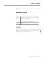
Summary of Changes
This publication contains new and revised information not in the last
release.
New and Revised Information
See the table for a summary of the major changes in this manual.
Chapter
Change
2
Addition of Before You Begin section
Addition of attention and warning statements
Update of the Communicate with Your Module section
Appendix A
Addition of information on how to configure modules in
RSLogix 5000
Change Bars
We marked with change bars (as shown with this paragraph) the areas
in this manual that are different from previous editions and indicate
the addition of new or revised information.
1
Publication 1734-UM006B-EN-P - August 2005
Summary of Changes
2
Notes:
Publication 1734-UM006B-EN-P - August 2005
Table of Contents
Preface
Preface
Purpose of This Manual. . . . . . . . . . .
Who Should Use This Manual . . . . . .
Related Products and Documentation.
Definitions . . . . . . . . . . . . . . . . . . . .
.
.
.
.
.
.
.
.
.
.
.
.
.
.
.
.
.
.
.
.
.
.
.
.
.
.
.
.
.
.
.
.
.
.
.
.
.
.
.
.
.
.
.
.
.
.
.
.
.
.
.
.
.
.
.
.
.
.
.
.
.
.
.
.
P-1
P-1
P-1
P-3
.
.
.
.
.
.
.
.
.
.
.
.
.
.
.
.
.
.
.
.
.
.
.
.
.
.
.
.
.
.
.
.
.
.
.
.
.
.
.
.
.
.
.
.
.
.
.
.
.
.
.
.
.
.
.
.
.
.
.
.
.
.
.
.
.
.
.
.
.
.
.
.
.
.
.
.
.
.
.
.
.
.
.
.
.
.
.
.
.
.
.
.
.
.
.
.
.
.
.
.
.
.
.
.
.
.
.
.
.
.
.
.
.
.
.
.
.
.
.
.
.
.
.
.
.
.
.
.
.
.
.
.
.
.
.
.
.
.
.
.
.
.
.
.
.
.
.
.
.
.
.
.
.
.
.
.
.
.
.
.
.
.
.
.
.
.
.
.
.
.
.
.
.
.
.
.
1-1
1-2
1-2
1-3
1-5
1-6
1-7
1-8
1-8
1-9
1-9
What This Chapter Contains . . . . . . . . . . . . . . . . . . . . .
Before You Begin . . . . . . . . . . . . . . . . . . . . . . . . . . . . .
Install the Mounting Base/Wiring Base Assembly . . . . . .
Install an I/O Module . . . . . . . . . . . . . . . . . . . . . . . . . .
Install the Removable Terminal Block . . . . . . . . . . . . . .
Remove a Mounting Base . . . . . . . . . . . . . . . . . . . . . . .
Wire the Modules . . . . . . . . . . . . . . . . . . . . . . . . . . . . .
Communicate with the Modules. . . . . . . . . . . . . . . . . . .
Default Data Map for the 1734-IJ/IK Counter Module
Configure Your Encoder/Counter Module . . . . . . . . . . .
Counter Configuration . . . . . . . . . . . . . . . . . . . . . . .
Filter Selection . . . . . . . . . . . . . . . . . . . . . . . . . . . . .
Scalar Selection . . . . . . . . . . . . . . . . . . . . . . . . . . . .
.
.
.
.
.
.
.
.
.
.
.
.
.
.
.
.
.
.
.
.
.
.
.
.
.
.
2-1
2-1
2-1
2-2
2-4
2-4
2-5
2-6
2-6
2-7
2-7
2-8
2-8
Chapter 1
About the Modules
What This Chapter Contains .
Operating Modes . . . . . . . . .
Counter Mode . . . . . . . . .
Encoder Modes . . . . . . . .
Period/Rate Mode . . . . . .
Operation of Scalar . . . . .
Rate Measurement Mode .
New Data Indicator . . . . .
Default Configuration. . . .
Operating Mode Features . . .
Operating Mode Features .
.
.
.
.
.
.
.
.
.
.
.
.
.
.
.
.
.
.
.
.
.
.
.
.
.
.
.
.
.
.
.
.
.
.
.
.
.
.
.
.
.
.
.
.
.
.
.
.
.
.
.
.
.
.
.
.
.
.
.
.
.
.
.
.
.
.
Chapter 2
Install the Modules
v
Publication 1734-UM006B-EN-P - August 2005
Chapter 3
Input and Output Data
What This Chapter Contains . . . . . . . . . . . . . . . . . . . . . .
Data Table . . . . . . . . . . . . . . . . . . . . . . . . . . . . . . . . . . .
Detailed Description of Data Table Information . . . . . . . .
Stored/Accumulated Channel Data (Input Word 2) . . .
Module/Channel Status and Programming Error Codes
(Input Words 3 and 4) . . . . . . . . . . . . . . . . . . . . . . . .
Configuration Data . . . . . . . . . . . . . . . . . . . . . . . . . . . . .
Counter Configuration (Configuration Word 1) . . . . . .
Filter Selection (Configuration Word 2 . . . . . . . . . . . .
Decimal Position (Configuration Word 3) . . . . . . . . . .
Word 4 is reserved. . . . . . . . . . . . . . . . . . . . . . . . . . .
Time Base and Gate Interval (Configuration Words
5 and 6) . . . . . . . . . . . . . . . . . . . . . . . . . . . . . . . . . .
Scalar (Configuration Word 7) . . . . . . . . . . . . . . . . . .
Scalar Selection . . . . . . . . . . . . . . . . . . . . . . . . . . . . .
Rollover (Configuration Word 8). . . . . . . . . . . . . . . . .
Preset (Configuration Word 9) . . . . . . . . . . . . . . . . . .
Safe State Values (Configuration Word 10) . . . . . . . . .
Communicate Real Time/Nonreal Time Information . . . . .
.
.
.
.
3-1
3-1
3-2
3-2
.
.
.
.
.
.
3-2
3-4
3-5
3-5
3-6
3-6
.
.
.
.
.
.
.
3-6
3-7
3-7
3-7
3-7
3-8
3-8
.
.
.
.
.
.
4-1
4-1
4-1
4-2
4-4
4-6
Chapter 4
Configure Your Module
What This Chapter Contains . . . . . . . . . . . . .
Configuration Overview . . . . . . . . . . . . . . . .
Add the Adapter to Your Network . . . . . .
Add I/O Modules to Your Network. . . . . .
Set Counter Parameters . . . . . . . . . . . . . . . . .
Check I/O Status and View/Edit the EDS File .
.
.
.
.
.
.
.
.
.
.
.
.
.
.
.
.
.
.
.
.
.
.
.
.
.
.
.
.
.
.
.
.
.
.
.
.
.
.
.
.
.
.
.
.
.
.
.
.
.
.
.
.
.
.
Chapter 5
Access Instantiated Instances
What This Chapter Contains . . . . . . . . . . . . . . . . . . . . . . . 5-1
Using Instantiated Instances. . . . . . . . . . . . . . . . . . . . . . . . 5-1
Assemblies . . . . . . . . . . . . . . . . . . . . . . . . . . . . . . . . . . . . 5-3
Chapter 6
Troubleshoot with the Indicators
What This Chapter Contains . . . . . . . . . . . . . . . . . . . . . . . 6-1
Use the Indicators for Troubleshooting . . . . . . . . . . . . . . . 6-1
Appendix A
Configure Modules in
RSLogix 5000
What This Appendix Contains . . . . . . . . . . . . . . . . . . . . . . A-1
Understand Data, Connections, and Communication Formats A-1
Configure Your Module. . . . . . . . . . . . . . . . . . . . . . . . . . . A-3
Work with the Fault/Program Action Dialog . . . . . . . . . . . . A-4
Work with the Counter Configuration Dialog . . . . . . . . . . . A-5
Index
vi
Publication 1734-UM006B-EN-P - August 2005
Preface
Purpose of This Manual
Who Should Use This
Manual
Read this manual for information about how to install, configure and
troubleshoot your Encoder/Counter module.
For This Information:
See:
About the Modules
Chapter 1
Install the Modules
Chapter 2
Encoder/Counter Module Input and Output Data
Chapter 3
Configure Your Encoder/Counter Module
Chapter 4
Access Instantiated Instances
Chapter 5
Troubleshoot with the Indicators
Chapter 6
You must be able to use RSNetworx software or similar configuration
software to set up and calibrate these modules. You must have the
capability to download and use Electronic Data Sheet files.
We assume you know how to do this in this manual. If you do not,
refer to your software user manuals or online help before attempting
to use these modules.
1
Publication 1734-UM006B-EN-P - August 2005
Preface
2
Related Products and
Documentation
For specification, safety approval, and other information refer to the
following.
• Publication Number 1734-IN005
Encoder/Counter Installation Instructions
For related 1734 products and documentation see the table.
Publication 1734-UM006B-EN-P - August 2005
Description
Cat. No.
Publication
Very High Speed Counter Modules
Installation Instructions
1734-VHSC5
1734-VHSC24
1734-IN003
Analog Input Modules
Installation Instructions
1734-IE2C
17340IE2V
1734-IN027
Analog Output Modules
Installation Instructions
1734-OE2C
1734-OE2V
1734-IN002
DeviceNet Communication Interface
Installation Instructions
1734-PDN
1734-IN057
Field Potential Distributor
Installation Instructions
1734-FPD
1734-IN059
POINT I/O 24V dc Expansion Power Supply
Installation Instructions
1734-EP24DC
1734-IN058
POINT I/O Selection Guide
1734 series
1734-SG001
Protected Output Module s
Installation Instructions
1734-OB2E
1734-OB4E
1734-OB8E
1734-IN056
Relay Output Modules
Installation Instructions
1734-OW2
1734-OW4
1734-IN055
Sink Input Modules
Installation Instructions
1734-IB2
1734-IB4
1734-IB8
1734-IN051
Source Output Modules
Installation Instructions
1734-IV2
1734-IV4
1734-IV8
1734-IN052
Wiring Base Assembly
Installation Instructions
1734-TB
1734-TBS
1734-IN511
Wiring Base Assembly
Installation Instructions
1734-TB3
1734-TB3S
1734-IN013
Preface
Definitions
3
The following define the intended operation of the Encoder/Counter
module.
Term
Definition
Lead Breakage
Typically requires a shunt resistor (across the load) to detect
3 levels of current/input states • Open (Wire Off, Device = ?)
• Off (Wire OK, Device Off)
• On (Wire OK, Device On)
This method does not check the input against a time base,
only that the device wiring (current loop) is intact
Missing Pulse
Typically uses an input pulse to reset a watchdog timer (fixed
or programmable HW). This method does detect “Lead
Breakage”, since a broken wire will time-out the watchdog.
Zero Frequency
Typically uses an input pulse to calculate an input frequency
and verify it is above an error threshold. This method does
detect Lead Breakage, since a broken wire will generate a
0Hz frequency.
Missing Pulse or Zero Frequency will also detect a customer
device stuck high or low, since the counter is monitoring for a
change in the input state. Currently, the Counter/Encoder
Modes do not have Zero Frequency Detection - the A & B
inputs are time independent, only looking for input edge
changes to increment/decrement the count value.
The Period/Rate and Continuous Rate modes do have Zero
Frequency Detection, since the Z input is monitored for Zero
Frequency in Firmware (A and B inputs are not used and not
monitored).
The Rate Measurement mode inherently has Zero Frequency
Detection, since no A pulses in any sample period are = 0Hz
(B and Z inputs are not used and not monitored).
Publication 1734-UM006B-EN-P - August 2005
Preface
4
Operational Mode
Zero Frequency Detection
Input Monitored
Counter
No
None
Encoder
No
None
Period/Rate
Yes
Z Only
Y
A Only
Rate Measurement
Publication 1734-UM006B-EN-P - August 2005
Chapter
1
About the Modules
What This Chapter Contains
Read this chapter to learn about types, features, and capabilities of
encoder/counter modules.
Module Description and
Features
Encoder/counter modules install into the Point I/O terminal base
(1734-TB or 1734-TBS) and interface with the Point I/O DeviceNet
Pass-through (1734-PDN) or the Point I/O DeviceNet Adapter
(1734-ADN).
An encoder/counter module serves as a signal conditioner, function
block, and counter between the customer process signals on the
terminal base and the POINTBus containing the command
information. The main functional blocks are the the following.
• Customer digital I/O interface
• Counter ASIC
• Microprocessor
The encoder/counter module accepts feedback from the following.
•
•
•
•
Encoders (either single-ended or differential)
Pulse generators
Mechanical limit switches
Frequencies up to 1 MHz
A filter is available with the following settings.
• 50 Hz
• 500 Hz
• 5 kHz
• 50 kHz
Turn the filter off to achieve the fastest counting rate.
The input voltage range is 5V dc (1734-IJ) or 15-24V dc (1734-IK). The
module returns the count or frequency in the form of a 24 bit binary
number (0 - 16,777,215) expressed in a 32 bit long word.
Each counter has a user-selectable preset and rollover value
associated with it.
1
Publication 1734-UM006B-EN-P - August 2005
1-2
About the Modules
Operating Modes
The encoder/counter modules operate in the modes shown in the
table.
Mode
Description
Counter Mode
Read incoming single phase pulses, return a binary
count
Encoder Mode
Read incoming 2 phase quadrature pulses, return a
binary count
Period/Rate Mode
Count internal clocks during the On period, return a
frequency
Rate Measurement Mode
Read pulses during the sample period, return a
frequency
The operation of the counter and encoder modes is nearly identical.
The difference between the two modes is in the type of feedback (1
phase versus 2 phase) for the count direction (up or down).
• In encoder mode, a transition is expected on B for counting to
proceed in a direction.
• In counter mode, the B input may be left at a static level.
Select operating modes by writing appropriate configuration data to
the module.
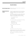
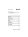
Counter Mode
The counter mode reads incoming pulses and returns a binary number
(0 - 16,777,215max) to the POINTBus. The counter mode only accepts
single phase inputs. The module determines the Phase B input state,
and counts up or down accordingly.
Channel A input is used as the counting pulse while channel B is used
to determine the direction.
[B = High, Count = Down; B = Low or floating (not connected), Count
= Up]
The Channel B input may be tied high or low for unidirectional
counting, or toggled for bidirectional counting.
Publication 1734-UM006B-EN-P - August 2005
About the Modules
1-3
Example of Counter Mode
A Input
Input A
B Direction
Input B
Z (Store Count)
Input Z
(Gate / Reset )
Single Phase Pulse Generator
1734-VHSC
Count Up
Count Down
A Input
B Input
Outputs
Updated
Continuously
Count
0
1
2
3
2
1
0
Encoder Mode
The encoder mode reads incoming pulses and returns a binary
number (0 - 16,777,215max) to the POINTBus. The encoder mode
only accepts 2 phase quadrature inputs. The module senses the
relationship between the 2 phases, and counts up or down
accordingly.
The two basic encoder types are absolute and incremental. A single
output incremental encoder is called a tachometer encoder. A dual
channel incremental encoder with one channel leading the other by
90° is called a quadrature encoder.
A system using a quadrature encoder may include an optional zero
pulse, or index, serving as a reference mark for system reset. The
principal disadvantage of a system using incremental encoders is that
a power interruption causes the loss of position reference, so a system
must be reinitialized or returned to a known zero position.
Absolute encoders typically have higher speed requirements (200 KHz
typical) for motion control applications. An absolute encoder has a
unique code associated with each position, so the exact position is
always known, even if the system power is turned off.
Publication 1734-UM006B-EN-P - August 2005
1-4
About the Modules
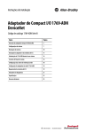
EXAMPLE
Example of Multiplying Encoder Mode X1
A
Input A
B
Input B
Z (Store Count)
Input Z
(Gate / Reset )
Quadrature Encoder
1734-VHSC
Forward Rotation
Reverse Rotation
A Input
B Input
1
2
3
2
1
0
X1 Count
1
2
3
4
1
2 3
4 5
6 7
5
6
5
4
3
2
1
0
8 7
6 5
4
3 2
1 0
X2 Count
8
9 10 11 12
11 10 9
X4 Count
Outputs
Updated
Continuously
X1 Multiplying Encoder Mode
Quadrature input signals are used to count on the leading (up
direction) OR trailing (down direction) edge of A for a bidirectional
count, and channel B is used to determine the direction.
[ B = leads A, Count = Down; B = follows A, Count = Up ]
X2 Multiplying Encoder Mode
Quadrature input signals are used to count on leading AND trailing
edges of A for a bidirectional count, and channel B is used to
determine the direction.
[ B = leads A, Count = Down; B = follows A, Count = Up ]
X4 Multiplying Encoder Mode
Quadrature input signals are used to count on leading AND trailing
edges of A AND B for a bidirectional count, and channel B is used to
determine the direction.
[ B = leads A, Count = Down; B = follows A, Count = Up ]
Publication 1734-UM006B-EN-P - August 2005
About the Modules
1-5
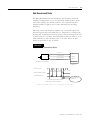
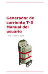
Period / Rate Mode
The Period/Rate Mode will return an incoming frequency and a total
accumulated count to the POINTBus, by gating an internal 5MHz
internal clock with an external signal.
This mode determines the frequency and total number of input pulses
by counting the number of internal 5MHz clock pulses over a
user-specified number of input signal pulses. At the end of the
specified number of pulses, the module returns the frequency
(0 - 1 MHz).
EXAMPLE
Example of Period/Rate Mode
A ( Not Used )
Input A
B ( Not Used )
Input B
Z
Encoder / Pulse Generator
Input Z
(Gate / Reset )
Scalar
5 MHz Clk
1734-IJ/IK
Z Input ( Pulse )
5 MHz Internal
Sampling Clock
Accumulated Count
1
10
20
Frequency
Updated Here
Assumes symmetrical pulse, 50% duty cycle, so Period = Sample Time On X 2 {On & Off}
Frequency = 1 / Period If Count = 20, Scalar = 1, and Clock Period = ( 1 / 5 MHz )
Frequency = 1 / [ ( 20 / 1 ) X ( 1 / 5 MHz ) X 2 ] = 125 kHz
As the frequency of the incoming pulse train at the Z (Gate/Reset)
terminal increases, the number of sampled pulses from the 5 MHz
clock decreases. Since accuracy is related to the number of pulses
received over the sample period, the accuracy decreases with
increasing frequencies at the Gate/Reset terminal. Refer to the
following Scaling table.
Publication 1734-UM006B-EN-P - August 2005
1-6
About the Modules
Relationship Between Sampled Pulses and Input Frequency
Input Frequency at Z
Gate/Reset Terminal
Sample Pulses for 1/2 Cycle
of Z Gate/Reset Pulse
2.5Hz
1M
5Hz
500k
10Hz
250k
20Hz
125k
50Hz
50k
100Hz
25k
200Hz
12.5k
500Hz
5k
1kHz
2.5k
2 Hz
1.25k
5kHz
500
10kHz
250
20kHz
125
50kHz
50
100kHz
25
Scaling the input frequency through the use of a scalar can lessen the
decrease in accuracy. A scalar value of 1 returns an accurate input
frequency only if incoming input pulses have a 50% duty cycle.
Operation of Scalar
In the Period/Rate mode, the scalar lets the incoming pulse train at the
Z Gate/Reset pin be divided by a user-defined number. There is one
scalar value for each counter. Acceptable values for the scalar are 1,
2, 4, 8, 16, 32, 64, and 128. The default value for each scalar is 1.
Note that a “0” scalar is equivalent to a “1”.
The product of the Sample Period times the scalar should be less than
6.71 seconds in order to avoid a zero frequency detect indication.
(5 MHz sample time = 200ns;
16,777,216 counts x 200ns x 2 half cycles of Z = 6.71 seconds)
Publication 1734-UM006B-EN-P - August 2005
About the Modules
1-7
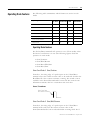
Rate Measurement Mode
The Rate Measurement mode determines the frequency and total
number of input pulses over a user-specified sample period. At the
end of the interval, the module returns a value representing the
sampled number of pulses and a value indicating the incoming
frequency.
When the count and frequency update, any associated outputs are
checked against their associated presets. Frequency is calculated by
dividing the accumulated count by the user selected time period, and
is returned in the read data. Allowable time periods are 10ms to 3s in
10ms increments, with a default value of 1s. Note that a “0” time
period is equivalent to the 1s default.
EXAMPLE
Example of Rate Measurement Mode
A Input
B ( Not Used )
Z ( Not Used )
(Gate / Reset )
Encoder/Pulse Generator
Input A
Input B
Input Z
Time Base
1734-IJ/IK
A Input ( Pulse )
Internal Sampling Gate
1
2
3
Accumulated Count
User Selectable Sample Period,
10ms to 2s in 10ms increments.
Frequency Calculated,
Updated Here
If Sample Period is 50ms, and Count = 3, then Frequency = 3 /50ms = 60Hz
Publication 1734-UM006B-EN-P - August 2005
1-8
About the Modules
New Data Indicator
A two-bit counter, C1 & C0, updates every time an "event" occurs,
indicating that new data is available in the Stored/Accumulated Count
words. Definitions for events are as follows.
• Any active gate transition in any of the Store Count (Counter or
Encoder) modes
• The end of the gate sample period in either the Period mode or
Rate mode
• The end of the programmed sample period in the Rate
Measurement mode.
To use these bits reliably, acquisition of data from the Counter Module
must occur faster than the events, which cause C1/C0 to increment.
When C1/C0 is updated, a Change Of State (COS) message can be
sent.
Default Configuration
The module's default configuration on startup is as follows.
•
•
•
•
•
•
•
Counter Mode
50Hz filter on A, B and Z
No time base
Rollover = 0x00FFFFFF
Preset = 0
No scalar
Counter Control Safe State = 0
To modify the default settings to those required for your application,
refer to the Input and Output section of this manual.
Publication 1734-UM006B-EN-P - August 2005
About the Modules
Operating Mode Features
1-9
The following table summarizes which features are active in each
mode:
Operating Feature
Counter
Up / Down
Encoder
X1, X2 & X4
Period
/Rate
Rate
Measurement
Preset
Y
Y
N
N
Rollover
Y
Y
N
N
Software Reset
Y
Y
Y
Y
Store Count - Z Gate / Reset 4 modes
Y
Y
N
N
Scale Input Count at Z Gate / Reset
N
N
Y
N
Z Gate / Reset Invert Bit
Y
Y
Y
N
Sample Period
N
N
N
Y
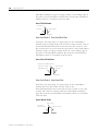
Operating Mode Features
The Z Gate/Reset Terminall will operate in one of four modes when
the Store Count feature is in use. The following figures detail the
operation in each mode:
•
•
•
•
Store/Continue
Store/Wait/Resume
Store-Reset/Wait/Start
Store-Reset/Start
Store Count Mode 1: Store/Continue
In mode 1, the rising edge of a pulse input on the Z Gate/Reset
terminal causes the current counter value to be read and stored in the
Read Data file. The counter continues counting. The stored count is
available in the Stored/Accumulated Count word. The stored count
information remains until it is overwritten with new data.
Store/Continue
Read, Store Count,
and Continue Counting
Store Count Mode 2: Store/Wait/Resume
In mode 2, the rising edge of a pulse input on the Z Gate/Reset
terminal reads and stores the current counter value in the
Stored/Accumulated Count word and inhibits counting while the Z
Publication 1734-UM006B-EN-P - August 2005
1-10
About the Modules
Gate/Reset terminal is high. Counting resumes on the falling edge of
the pulse at the Z Gate/Reset terminal. The stored count information
remains until it is overwritten with new data.
Store/Wait/Resume
Stop Counting
Store Count
Resume Counting
Store Count Mode 3: Store-Reset/Wait/Start
In mode 3, the rising edge of a pulse input on the Z Gate/Reset
terminal stops counting, reads, and stores the current counter value in
the Stored/Accumulated Count word, and resets the counter to zero.
The counter does not count while the input pulse on the Z Gate/Reset
terminal is high. Counting resumes from zero on the falling edge of
the pulse at the Gate/Reset terminal. The stored count information
will remain until it is overwritten with new data.
Store-Reset/Wait/Start
Counter has stopped Counting
Stop Count, Store,
and Reset to zero
Start Counting
from zero
Store Count Mode 4: Store-Reset/Start
In mode 4, the rising edge of a pulse input on the Z Gate/Reset
terminal will store the current counter value in the
Stored/Accumulated Count word and reset the counter to zero. The
counter will continue counting while the Z Gate/Reset terminal is
high. The stored count information will remain until it is overwritten
with new data.
Store-Reset/Start
Start Counting
Store Count,
and Reset to zero
Publication 1734-UM006B-EN-P - August 2005
Continue Counting
Chapter
2
Install the Module
What This Chapter Contains
Read this chapter for information about how to install Encoder/
Counter modules.
For information about how to
See page
Before You Begin
2-1
Install the Mounting Base and Wiring Base Assembly
2-1
Install the Module
2-4
Install the Removable Terminal Block
2-6
Remove a Mounting Base
2-6
Wire the Modules
2-7
Communicate with Your Module
2-9
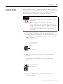
Before You Begin
ATTENTION
Preventing Electrostatic Discharge
This equipment is sensitive to electrostatic discharge,
which can cause internal damage and affect normal
operation. Follow these guidelines when you handle
this equipment:
• Touch a grounded object to discharge potential
static.
• Wear an approved grounding wriststrap.
• Do not touch connectors or pins on component
boards.
• Do not touch circuit components inside the
equipment.
• If available, use a static-safe workstation.
• When not in use, store the equipment in
appropriate static-safe packaging.
1
Publication 1734-UM006B-EN-P - August 2005
2-2
Install the Module
ATTENTION
Environment and Enclosure
This equipment is intended for use in a Pollution
Degree 2 industrial environment, in overvoltage
Category II applications (as defined in IEC
publication 60664-1), at altitudes up to 2000 meters
without derating.
This equipment is considered Group 1, Class A
industrial equipment according to IEC/CISPR
Publication 11. Without appropriate precautions,
there may be potential difficulties ensuring
electromagnetic compatibility in other environments
due to conducted as well as radiated disturbance.
This equipment is supplied as open-type equipment.
It must be mounted within an enclosure that is
suitably designed for those specific environmental
conditions that will be present and appropriately
designed to prevent personal injury resulting from
accessibility to live parts. The interior of the
enclosure must be accessible only by the use of a
tool. Subsequent sections of this publication may
contain additional information regarding specific
enclosure type ratings that are required to comply
with certain product safety certifications.
See NEMA Standards publication 250 and IEC
publication 60529, as applicable, for explanations of
the degrees of protection provided by different types
of enclosure. Also, see the appropriate sections in
this publication, as well as the Allen-Bradley
publication 1770-4.1 (Industrial Automation Wiring
and Grounding Guidelines), for additional installation
requirements pertaining to this equipment.
Use these Series C modules with the following:
• ControlNet adapters
with RSLogix 5000 software, version 11 or higher
• DeviceNet adapters
• EtherNet/IP adapters
with RSLogix 5000 software, version 11 or higher
• PROFIBUS adapters
Publication 1734-UM006B-EN-P - August 2005
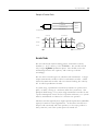
Install the Module
The wiring base assembly (1734-TB or 1734-TBS) consists of a
mounting base (cat. no. 1734-MB) and a removable terminal block
(catalog number 1734-RTB or 1734-RTBS).
You can install the assembly, or just the mounting base. To install the
mounting base and wiring base assembly on the DIN rail, proceed as
follows.
ATTENTION
POINT I/O is grounded through the DIN rail to chassis
ground. Use zinc-plated, yellow-chromated steel DIN
rail to assure proper grounding. The use of DIN rail
materials (such as aluminum and plastic) that can
corrode, oxidize, or are poor conductors can result in
improper or intermittent grounding.
Secure DIN rail to mounting surface approximately
every 200 mm (7.8 inches).
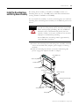
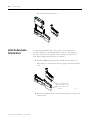
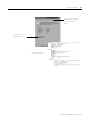
1. Position the mounting base and wiring base assembly vertically
above the installed units (adapter, power supply or existing
module).
2. Slide the mounting base down so that the interlocking side
pieces engage the adjacent module or adapter.
Slide-in Writable Label
E:
M
St od
at u
us le
N
St etw
O atu o
D s rk
1
0
2
S 4V
O ou DC
ut rc
pu e
t
N
Module Locking Mechanism
3
1
O 73
B 4
4E
2
1
Install the Mounting Base
and Wiring Base Assembly
2-3
Insertable I/O Module
Module Wiring Diagram
Mechanical Keying
(orange)
DIN Rail Locking Screw
(orange)
RTB Removing Handle
Removable Terminal Block (RTB)
Interlocking Side Pieces
Mounting Base
41825
Publication 1734-UM006B-EN-P - August 2005
2-4
Install the Module
3. Press firmly to seat the mounting base on the DIN rail.
The mounting base snaps into place.
M
Stod
ule
atus
Ne
Stattwor
us k
NO
DE
:
0
24
So VDC
Ouurce
tput
1
2
3
17
OB34
4E
4. To remove the mounting base from the DIN rail:
a. Remove any installed module and any module immediately to
the right.
b. Use a small-bladed screwdriver to rotate the DIN rail locking
screw to a vertical position.
This releases the locking mechanism.
c. Lift straight up to remove the mounting base.
d. Repeat this procedure for the next mounting base assembly.
ATTENTION
Publication 1734-UM006B-EN-P - August 2005
Do not discard the end cap shipped with an adapter
or communication interface. Use this end cap to cover
the exposed interconnections on the last mounting
base on the DIN rail. Failure to do so could result in
equipment damage or injury from electric shock.
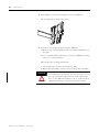
Install the Module
Install the Module
2-5
Install the module before or after base installation. Make sure that you
correctly key the mounting base before installing the module into the
mounting base. In addition, make sure you position the mounting
base locking screw horizontal, as referenced to the base.
WARNING
When you insert or remove the module while
backplane power is on, an electrical arc can occur.
This could cause an explosion in hazardous location
installations.
Be sure that power is removed or the area is
nonhazardous before proceeding. Repeated electrical
arcing causes excessive wear to contacts on both the
module and its mating connector. Worn contacts may
create electrical resistance that can affect module
operation.
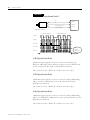
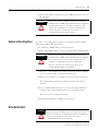
1. Using a bladed screwdriver, rotate the keyswitch on the
mounting base clockwise until the number required for the type
of module you are installing aligns with the notch in the base.
1734-IJ - Position 2
1734-IK - Position 2
Turn the keyswitch to align
the number with the notch.
Notch
(position 3 shown)
44009
2. Make sure the DIN rail locking screw is in the horizontal
position.
You cannot insert the module if you unlock the locking
mechanism.
Make sure the DIN rail
locking screw is in the
horizontal position.
44010
3. Insert the module straight down into the mounting base,
and press to secure.
Publication 1734-UM006B-EN-P - August 2005
2-6
Install the Module
M
St od
at u
us le
3
1
O 73
B 4
4E
2
1
0
2
S 4V
O ou DC
u t rc
pu e
t
N
N
S et
t w
O a tu o
D s rk
E:
The module locks into place.
44012
Install the Removable
Terminal Block
A removable terminal block comes with your mounting base
assembly. Pull up on the RTB handle to remove, and replace as
necessary without removing any of the wiring. To reinsert the
removable terminal block, proceed as follows.
1. Insert the RTB end opposite the handle into the base unit.
This end has a curved section that engages with the mounting
base.
Hook the RTB end into
the mounting base end,
and rotate until it locks
into place.
44011
2. Rotate the terminal block into the mounting base until it locks
itself in place.
Publication 1734-UM006B-EN-P - August 2005
Install the Module
2-7
3. If an I/O module is installed, snap the RTB handle into place on
the module.
WARNING
Remove a Mounting Base
When you connect or disconnect the removable
terminal block (RTB) with field-side power applied,
an electrical arc can occur. This could cause an
explosion in hazardous location installations. Be
sure that power is removed or the area is
nonhazardous before proceeding.
To remove a mounting base, remove any installed module and the
removable terminal block (if wired).
1. Unlatch the RTB handle on the I/O module.
2. Pull on the RTB handle to remove the removable terminal block.
WARNING
When you connect or disconnect the removable
terminal block (RTB) with field-side power applied,
an electrical arc can occur. This could cause an
explosion in hazardous location installations.
Be sure that power is removed or the area is
nonhazardous before proceeding.
3. Press in on the module lock on the top of the module and pull
up on the I/O module to remove from the base.
4. Remove the module to the right of the base you are removing.
The interlocking portion of the base sits under the adjacent
module.
5. Use a small-bladed screwdriver to rotate the orange DIN rail
locking screw on the mounting base to a vertical position.
This releases the locking mechanism.
6. Lift the mounting base straight up to remove.
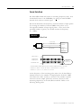
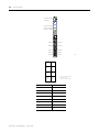
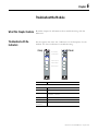
Wire the Modules
WARNING
If you connect or disconnect wiring while the field-side
power is on, an electrical arc can occur. This could
cause an explosion in hazardous location installations.
Be sure that power is removed or the area is
nonhazardous before proceeding.
Publication 1734-UM006B-EN-P - August 2005
2-8
Install the Module
Module Status
Network
Status of Input A
Status of Input B
Status of Input Z
Input A
Input Aret
Input B
Input Bret
Input Z
Input Zret
Chassis
Ground
Chassis
Ground
1
0
A
2
Aret
3
B
4
Bret
5
Zret
Z
6
Publication 1734-UM006B-EN-P - August 2005
Chas
Gnd
7
Chas
Gnd
A, B, and Z , and Aret, Bret,
and Zret are inputs
Chas Gnd = Chassis ground
Termination
Definition
0
A
1
Aret
2
B
3
Bret
4
Z
5
Zret
6
Chassis ground
7
Chassis ground
42016
Install the Module
Communicate with Your
Module
2-9
POINT I/O modules send (consume) and receive (produce) I/O
messages. You map these messages into the processor’s memory.
This module produces 6 or 10 bytes of input data (scanner Rx)
(status). It consumes 1 byte of I/O data (scanner Tx). Use parameters
11 and 12 to select assembly 101, 102, or 103 for data produced by the
module.
When you send a configuration to the module, you check it for
consistency before applying it. Monitor the PE bit with your user
program to isolate any problems with an improperly configured
module. If the configuration is acceptable, the counter ASIC is
disabled while the ASIC is loaded with new operational parameters.
Outputs can turn off during this reconfiguration.
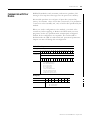
Default Data Map
Message size: 6 or 10 Bytes
15
14
13
Produces
(scanner Rx)
12
11
10
09
08
07
06
05
04
03
02
01
00
C
0
Z
D
0
Channel 0 value of present counter state (LSW)
Channel 0 value of present counter state (MSW)
P
E
E
F
N
R
0
0
0
0
0
0
Z
S
B
S
A
S
C
1
Where:PE = Programming error
EF = EEPROM fault status
NR = Not ready status bit
ZS = Z input status
BS = B input status
AS = A input status
C1/C0 = Stored data count
ZD = Zero frequency detected
LSW = Least significant word
MSW= Most significant word
Message size:
Consumes (scanner Tx)
07
06
05
04
03
0
0
0
0
0
02
VR
01
CP
00
CR
Where:VR = Value reset of stored/accumulated count
CP = Counter preset
CR = Counter reset
Publication 1734-UM006B-EN-P - August 2005
2-10
Install the Module
Module Configuration
Parameter
Set/Get
Description
Bytes
1
Set/Get
Counter Configuration
1
2
Set/Get
Filter Selection
1
3
Set/Get
Decimal Position
1
4
Set/Get
Reserved
1
5
Set/Get
Time Base Value
2
6
Set/Get
Gate Interval
1
7
Set/Get
Channel Scalar
1
8
Set/Get
Channel Rollover Value
4
9
Set/Get
Channel Preset Value
4
10
Set/Get
Counter Control Safe State
1
11
Set/Get
Requested Poll Produce Assembly
1
12
Set/Get
Requested Change of State Produce Assembly
1
Counter Configuration
07
06
ZI
Publication 1734-UM006B-EN-P - August 2005
05
04
03
02
01
00
0
0
0
0
Counter
0
0
0
1
Encoder X1
0
0
1
0
Encoder X2
MD
CF
Counter 0
0
0
1
1
Not used
0
1
0
0
Encoder X4
0
1
0
1
Period/Rate
0
1
1
0
Not used
0
1
1
1
Rate Measurement
0
0
0
Store Count Disabled
0
0
1
Mode 1 - store-continue
0
1
0
Mode 2 - store-wait-resume
0
1
1
Mode 3 - store, reset-wait-start
1
0
0
Mode 4 - store, reset-start
1
0
1
Reserved
1
1
0
Reserved
1
1
1
Reserved
0
Z input - 0 = not inverted
1
Z input - 1 = inverted
Install the Module
2-11
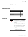
Filter Selection
07
06
05
04
0
ZF
BF
AF
03
02
01
00
FS
0
0
0
0
No Filter
0
0
0
1
50kHz (10µs + 0µs/-1.6µs)
0
0
1
0
5kHz (100µs + 0µs/-13.2µs)
0
1
0
0
500Hz (1.0ms + 0µs/-125µs)
1
0
0
0
50Hz (10ms + 0ms/-1.25ms)
0
A input not filtered
1
A input filtered
0
B input not filtered
1
B input filtered
0
Z input not filtered
1
Z input filtered
Assumes a 50% duty cycle signal.
Scalar Selection
07
06
05
04
03
02
01
00
0
0
0
0
0
0
0
1
Z - Fmin = 0.149Hz
0
0
0
0
0
0
1
0
Z/2 - Fmin = 0.298Hz
0
0
0
0
0
1
0
0
Z/4 - Fmin = 0.596Hz
0
0
0
0
1
0
0
0
Z/8 - Fmin = 1.192Hz
0
0
0
1
0
0
0
0
Z/16 - Fmin = 2.384Hz
0
0
1
0
0
0
0
0
Z/32 - Fmin = 4.768Hz
0
1
0
0
0
0
0
0
Z/64 - Fmin = 9.537Hz
1
0
0
0
0
0
0
0
Z/128 - Fmin = 19.073Hz
1
Scalar1
Where Fmin indicates the frequency at which the zero frequency detect is asserted
due to counter overflow.
Publication 1734-UM006B-EN-P - August 2005
2-12
Install the Module
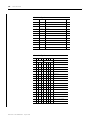
Assemblies
The Encoder and Counter Module uses several words to communicate real-time
input and output data as well as non-real-time module information (for example,
description, revision, etc.) and configuration. This shows the words that you can
exchange. You can read (get) or write (set) data using an Explicit Message.
Instance
Services
Field
Bytes
#101 (0x65)
Get
Present Channel Data
4
Status
2
Stored Channel Data
4
Status
2
Present Channel Data
4
Stored Channel Data
4
#102 (0x66)
#103 (0x67)
Get
Status
2
#104 (0x68)
Get
Programming Error Code
2
#105 (0x69)
Set/Get
Counter Control
1
#106 (0x6a)
Set/Get
Counter Configuration
1
Filter Selection
1
Decimal Position
1
Reserved
1
Time Base
2
#123 (0x7b)
Publication 1734-UM006B-EN-P - August 2005
Get
Set/Get
Gate Interval
1
Scalar
1
Rollover Value
4
Preset Value
4
Counter Control SSV
1
Counter Configuration
1
Filter Selection
1
Decimal Position
1
Reserved
1
Time Base
2
Gate Interval
1
Scalar
1
Rollover Value
4
Preset Value
4
Counter Control SSV
1
Alignment (reserved = 0)
1
Chapter
3
Input and Output Data
That This Chapter Contains
Data Table
Read this chapter to learn about the input/output data table of your
1734-IJ and 1734-IK.
For more information about:
See page:
Data Table
3-1
Detailed Description of Data Table Information
3-2
Configuration Data
3-4
Communicate Real Time/Nonreal Time Information
3-8
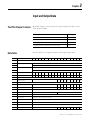
See the table for a complete format of the input/output data..
15
14
13
12
11
10
09
08
07
06
05
04
03
02
01
0
Input Information
Present Channel Data
32-bit Value of the present counter state
Stored Channel Data
32-bit value of the stored/accumulated count
Status
PE
EF
NR
0
0
0
0
0
0
ZS
BS
AS
C1
C0
ZD
0
Programming Error Code
PE
0
0
0
0
E10
E9
E8
E7
E6
E5
E4
E3
E2
E1
E0
0
0
0
0
0
VR
CP
CR
Counter Configuration
ZI
MD
MD
MD
CF
CF
CF
CF
Filter Selection
0
ZF
BF
AF
FS
FS
FS
FS
0
0
0
VR
CP
CR
Output Information
Counter Control
Configuration Information
Decimal Position
8-bit value used to modify the present channel data display
Reserved
Time Base
16-bit value used to set the time base
Gate Interval
8-bit value used to set the gate interval
Scalar
8-bit value used to divide the Z input by 2n
Rollover Value
32-bit value at which the counter is commanded to rollover
Preset Value
32-bit value the counter is to be set to when CP is asserted
Counter Control SS Value
1
0
0
Publication 1734-UM006B-EN-P - August 2005
3-2
Input and Output Data
Detailed Description of
Data Table Information
Present Channel Data (Input Word 1)
This is a 32 bit unsigned long word value representing the current
count of the 24 bit counter (configurations: count [0], x1 encoder [1],
x2 encoder [2], x4 encoder [4]) or the frequency (configurations:
period/rate [5], rate measurement [7]). The range of values is 0 ≤value
≤0x00FFFFFF (16,777,215).
Stored/Accumulated Channel Data (Input Word 2)
This is a 32 bit unsigned long word value representing the stored
count of the counter at the time of some specified event. In counter
configurations (configurations: count [0], x1 encoder [1], x2 encoder
[2], x4 encoder [4]) without store modes selected, these words are not
updated. With store modes selected, they are the stored value of the
counter at the time of the specified event (ex: rising edge of Z input).
In period/rate [5] configurations, it is the total accumulation of
unscaled Z pulses (for example, if scaling is set to 128, after 128 Z
pulses the accumulator will increase by 128 counts).
The maximum frequency that accumulation can follow in period/rate
mode is 200Hz x scalar value (ex: 200Hz x 128 is 25kHz). Finally, in
rate measurement [7] configuration, it is the total number of pulses
seen at the A input accumulated over each period as specified by the
product of the time base x gate interval. The range of values occupies
the entire 32 bit size from 0 ≤value ≤0xFFFFFFFF (4,294,967,295).
Changing the configuration does not clear these words.
Module/Channel Status and Programming Error Codes (Input
Words 3 and 4)
Programming Error bit (PE) - If an incomplete, incorrect or
conflicting set of configuration parameters are sent to the module, the
PE bit will be asserted and an error code will be placed in the
Programming Error Code word (assembly 6816). The module will not
enter a normal operational state.
Publication 1734-UM006B-EN-P - August 2005
Input and Output Data
3-3
Bit definitions for the error code are:
E10:
Reserved
E9:
The decimal point position is outside of acceptable range.
E8:
Reserved
E7:
Reserved
E6:
A configuration was selected that requires the scalar and none
was programmed OR Multiple scalars were selected.
E5:
The preset is out of range ( > 0x00FFFFFF).
E4:
A rollover of zero was programmed OR Rollover is out of
range ( > 0x01000000).
E3:
A configuration requiring time base was selected and no gate
interval was set OR Gate interval is out of range ( > 200) OR
Product of time base and gate interval is greater than 3
seconds.
E2:
A time base was entered that is not a multiple of 10 OR Time
base is out of range ( > 3000, or 3 seconds).
E1:
ZF/BF/AF were selected and no filter was programmed OR
Multiple filters were selected.
E0:
A reserved configuration/mode was programmed.
EEPROM Fault status bit (EF) - If a fault is detected with the
EEPROM during power up tests, this bit is asserted to 1. It indicates
that the content of the EEPROM has been corrupted, most likely
caused by loss of power during an executing write.
Not Ready status bit (NR) - Whenever power is applied to the
module, the hardware must be initialized. During this time, the NR bit
will be asserted and the green module status indicator will flash.
Z input Status (ZS) - This bit indicates the present status of the Z
input (1 indicates Z is ON, 0 indicates Z is OFF). This bit is unaffected
by Z Invert, ZI, in the Counter Configuration word.
B input Status (BS) - This bit indicates the present status of the B
input (1 indicates B is ON, 0 indicates B is OFF).
A input Status (AS) - This bit indicates the present status of the A
input (1 indicates A is ON, 0 indicates A is OFF).
C[1,0] Stored data count - This count cycles through [ 0 0 ], [ 0 1 ], [ 1
0 ], [ 1 1 ], [ 0 0 ]…Each time the stored/accumulated count words are
updated, C[1,0] is incremented. This feature assumes the host’s sample
rate (including network delay and program scan) is as fast or faster
than the frequency of the event that updates C[1,0].
Publication 1734-UM006B-EN-P - August 2005
3-4
Input and Output Data
Zero frequency Detected (ZD) - This bit is operational when
frequency configurations are programmed (configurations: period/rate
[5], rate measurement [7]).
In period/rate [5] configuration, counts are acquired during
the ON state of the Z input. At very low frequencies the counter
saturates, indicating a zero frequency detect. The time it takes to
determine a zero frequency in these two configurations can be
as long as 6.7 seconds ( 16,777,216 counts x 1/5MHz x 2 half
cycles of Z ).
In rate measurement [7] configuration pulses on the A input
are counted over a sample interval specified by the time base.
The time it takes to determine a zero frequency in this
configuration will be determined by the sample interval, for
example, time base = 0.300 second (300 milliseconds) to
determine ZF.
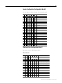
Configuration Data
The following represents the configuration data used by the module.
Parameter
Publication 1734-UM006B-EN-P - August 2005
Configuration Information
Size (bytes)
1
Set/Get
Counter Configuration
1
2
Set/Get
Filter Selection
1
3
Set/Get
Decimal Position
1
4
Set/Get
Reserved
1
5
Set/Get
Time Base
2
6
Set/Get
Gate Interval
1
7
Set/Get
Scalar
1
8
Set/Get
Rollover Value
4
9
Set/Get
Preset Value
4
10
Set/Get
Counter Control SS Value
1
Input and Output Data
3-5
Counter Configuration (Configuration Word 1)
Use this byte to select the type of counter desired.
07
06
ZI
05
04
03
02
0
0
0
0
Counter
0
0
0
1
Encoder X1
0
0
1
0
Encoder X2
0
0
1
1
Reserved
0
1
0
0
Encoder X4
0
1
0
1
Period/Rate
0
1
1
0
Reserved
0
1
1
1
Rate Measurement
MD
01
00
CF
Counter 0
0
0
0
Store Count Disabled
0
0
1
Mode 1 - store/continue
0
1
0
Mode 2 - store/wait/resume
0
1
1
Mode 3 - store, reset/wait/start
1
0
0
Mode 4 - store, reset/start
1
0
1
Reserved
1
1
0
Reserved
1
1
1
Reserved
0
Z input - 0 = not inverted
1
Z input - 1 = inverted
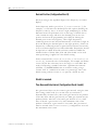
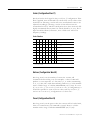
Filter Selection (Configuration Word 2
This byte sets the A/B/Z input filters
Filter Selection
07
06
05
04
0
ZF
BF
AF
03
02
01
00
FS
0
0
0
0
No Filter
0
0
0
1
50kHz (10µs + 0µs/-1.6µs)
0
0
1
0
5kHz (100µs + 0µs/-13.2µs)
0
1
0
0
500Hz (1.0ms + 0µs/-125µs)
1
0
0
0
50Hz (10ms + 0ms/-1.25ms)
0
A input not filtered
1
A input filtered
0
B input not filtered
1
B input filtered
0
Z input not filtered
1
Z input filtered
Publication 1734-UM006B-EN-P - August 2005
3-6
Input and Output Data
Decimal Position (Configuration Word 3)
This byte changes the significant digits of the frequency or counter
display.
In the frequency modes (period/rate [5], rate measurement [7]) for
example, a -2 will move the decimal point left 2 places, dividing the
frequency value by 100, a +1 moves it right, multiplying by 10. The
firmware checks for placement to be in the range -4 ≤value ≤+2. A
value outside the range will move the decimal point to the zero
position and assert the programming error (PE) bit. Moving the
decimal point to the left (negative), allows high frequencies,
commonly present in rate measurement mode, to fit within a single 16
bit word. Moving the decimal point to the right (positive), allows low
frequencies, commonly present in period and continuous rate modes,
to have resolution displayed to 0.1Hz and 0.01Hz. Frequencies should
be kept below 3.2kHz for 0.1Hz resolution and below 320Hz for
0.01Hz. Scalars of Z/128, Z/64, Z/32 and Z/16 should not be used
when positioning is applied. 0 is the default setting.
In the counter modes (counter [0], x1 encoder [1], x2 encoder [2], x4
encoder [4]), it attenuates the counter display, for example, 20 divides
count+1 by 20. The value may be in the range 0 < value ≤255. The
result of requesting a number other than 1 performs the function:
(COUNT + 1)/ATTENUATION. This is useful for scaling a large
counter value to a smaller 16 bit value or a percentage. One is the
default setting and zero reverts to 1 to prevent a divide by zero.
Word 4 is reserved.
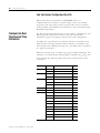
Time Base and Gate Interval (Configuration Words 5 and 6)
The gate interval byte sets the counter’s gate intervall using the time
base setting (16-bit word 5) as its time unit. (its resolution is
determined by the time base). The actual gate interval is the product
of the time base and the gate interval (ex: 50ms gate interval may be
produced with a time base of 10 and a gate interval of 5 or a time
base of 50 and a gate interval of 1). The maximum value of the
product of time base x gate interval is 3 seconds. The gate interval
must be entered when rate measurement [7] configurations are used.
The maximum value is 200.
Publication 1734-UM006B-EN-P - August 2005
Input and Output Data
3-7
Scalar (Configuration Word 7)
This bytel scales the Z signal in the period/rate [5] configuration. If the
filter is applied, then the filtered Z is scaled. Only one bit of the scalar
should be set. Selecting a scalar will cause accumulated counts to be
adjusted accordingly (selecting a scalar of 128 will increase the
accumulated count by 128 after 128 Z pulses have been received). We
highly recommend that anytime Z is scaled (divide by 2, 4, 8), the Z
input should be filtered, otherwise, noise could cause erroneous
frequency readings.
Scalar Selection
07
06
05
04
03
02
01
00
Scalar1
0
0
0
0
0
0
0
1
Z - Fmin = 0.149Hz
0
0
0
0
0
0
1
0
Z/2 - Fmin = 0.298Hz
0
0
0
0
0
1
0
0
Z/4 - Fmin = 0.596Hz
0
0
0
0
1
0
0
0
Z/8 - Fmin = 1.192Hz
0
0
0
1
0
0
0
0
Z/16 - Fmin = 2.384Hz
0
0
1
0
0
0
0
0
Z/32 - Fmin = 4.768Hz
0
1
0
0
0
0
0
0
Z/64 - Fmin = 9.537Hz
1
0
0
0
0
0
0
0
Z/128 - Fmin = 19.073Hz
1 Where Fmin indicates the frequency at which the zero frequency detect is asserted
due to counter overflow.
Rollover (Configuration Word 8)
This long word sets the number of counts the counter will
accumulate before rolling over. For example, a value of 1000 will
produce a count sequence of: 998, 999, 0, 1, 2…while incrementing
or 2, 1, 0, 999, 998…while decrementing. Rollover is a 32 bit number
with a useable range of 1 ≤value ≤0x01000000 (16,777,216). In count
[0], x1 encoder [1], x2 encoder [2] and x4 encoder [4] configurations, it
should be specified to some non-zero value; and in period/rate [5],
and rate measurement [7] configurations is a ‘don’t care’.
Preset (Configuration Word 9)
This long word sets the preset value the counter will be loaded with,
when a Counter Preset, CP, command is issued. Preset is a 32 bit
number with a range of 0 ≤value ≤0x00FFFFFF (16,777,215).
Publication 1734-UM006B-EN-P - August 2005
3-8
Input and Output Data
Safe State Values (Configuration Word 10)
When either the host transitions to PROGRAM mode or a
communication fault (broken network cable) occurs, the module
copies the safe state word (counter control value) into its real-time
working buffer. The definitions are identical to those described under
Real-time Output Data.
Communicate Real
Time/Nonreal Time
Information
The Encoder/Counter Module uses several words to communicate real
time input and output data as well as non-real time module
information (such as description and revision) and configuration.
Assembly 101 is produced for a polled connection. Assembly 102 is
produced for a Change Of State (COS) connection. Assemblies 103,
104, and 106 are by Explicit message only. Assembly 105 is consumed
in a polled connection.
Data may be read (get) or written (set) using an Explicit Message. For
example, to read the Present Channel Data, assembly 10110 (6516) can
be requested. The following table shows the words which can be
exchanged.
Instances
Services
Field
Bytes
#101 (0x65)
Get
Present Channel Data
4
Status
2
Stored Channel Data
4
Status
2
Present Channel Data
4
Stored Channel Data
4
Status
2
#102 (0x66)
#103 (0x67)
Publication 1734-UM006B-EN-P - August 2005
Get
Get
#104 (0x68)
Get
Programming Error Code
2
#105 (0x69)
Set/Get
Counter Control
1
#106 (0x6a)
Set/Get
Counter Configuration
1
Filter Selection
1
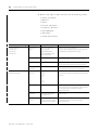
Decimal Position
1
Reserved
1
Time Base
2
Gate Interval
1
Scalar
1
Rollover Value
4
Preset Value
4
Counter Control SSV
1
Chapter
4
Configure Your Module
What This Chapter Contains
This chapter describes how to configure your Encoder/Counter
modules with RSNetworx.
For more information about:
Configuration Overview
See page:
Configuration Overview
4-1
Add the Adapter to Your Network
4-1
Add I/O Modules to Your Network
4-2
Set Counter Parameters
4-4
Check I/O Status and View the EDS File
4-6
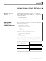
You must use the RSNetworx for DeviceNet software to configure
your module. You can configure the module while it is:
• online
or
• offline
This chapter shows configuration in the online mode. Configuration
dialogs appear similar in both modes. The primary difference is that if
you make changes offline, you must go on line before the
configuration changes take effect.
Add the Adapter to Your Network
Follow these steps:
1. Start the RSNetworx for DeviceNet software.
1
Publication 1734-UM006B-EN-P - August 2005
4-2
Configure Your Module
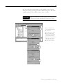
2. Add the communication device as shown below. (In this case,
the chosen device was a 1734-ADN DeviceNet Scanner.)
1. Click here to expand the list
of communication adapters.
2. Double-click here to choose
the scanner. You can also
click and drag the scanner
name onto the network.
Make sure you choose the
1734-ADN Point I/O Scanner.
The scanner appears
on the network.
IMPORTANT
The scanner must always exist on the DeviceNet
network at Node 00.
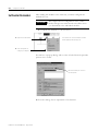
Add I/O Modules to Your Network
After you add the communication device, you must add the POINT
I/O modules connected to the scanner on the PointBus.
1. Add modules as shown below. (In this case, the communication
device shown is a 1770-KFD.)
.
1. Click here to expand the list
of Specialty modules.
2. Double-click on the catalog
number to choose the
module. You can also click
and drag the module name
onto the network.
Publication 1734-UM006B-EN-P - August 2005
Configure Your Module
4-3
The out-of-the-box node setting for 1734 modules is 63. You can
change the setting by using the node commissioning tool. The node
commissioning tool is available either online or offline.
IMPORTANT
If you commission a node on line, you must power
down your system before the change takes place.
1
2
3
1. Go to the pulldown Tools.
Select Node Commissioning.
2. Click on Browse.
3. Select the module to change.
4. The node commissioning
dialog returns. It displays the
node number and data rate.
5. Change the node number and
Apply. The dialog will then
identify the new setting.
6. Click on Close to continue.
4
5
6
Publication 1734-UM006B-EN-P - August 2005
4-4
Configure Your Module
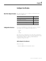
Set Counter Parameters
After adding the module to the network, you must configure the
modules for use.
IMPORTANT
This chapter shows configuration in the online
mode. Changes set in this mode take effect when
you download to the individual module.
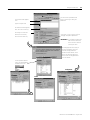
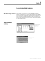
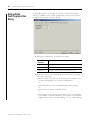
1. Configure the modules as shown below.
1. Right-click on the module.
You can also left click on the module or name
and the property dialog will pop up.
2. Click on Properties to
configure your adapter.
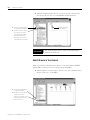
You will see a pop-up dialog with a series of tabs. Each tab provides
options view or edit.
These are the tabs you click on to
view the options.
Refer to the dialogs for an explanation of its features.
Publication 1734-UM006B-EN-P - August 2005
Configure Your Module
4-5
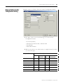
Click on the Device parameters tab
to get to the dialog for setting the
parameters.
The module’s name appears
here.
Type a description here.
The module’s address appears
here. (This field is read only.)
This dialog also shows the
module’s device identity.
These fields are read-only.
At any point, you can click here to finish
changing configuration parameters.
IMPORTANT: If configuration changes are
made in offline mode, they
do not take effect until the
system goes online.
This dialog appears after clicking on
the Device parameters tab. If you
want the existing parameters
uploaded from the module, select
Upload. The following dialog will
then show the existing parameters
set on the module.
Use this pulldown menu to
edit or view the parameters.
Available choices are:
Configuration
PointBus
Status
Publication 1734-UM006B-EN-P - August 2005
4-6
Configure Your Module
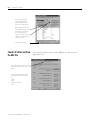
To configure your module,
select Configuration and
modify the parameters as
desired for your application.
When complete, download to
your module by clicking on the
Download to Device button.
You can download each
change as you make it using
“Single,” or download all your
changes using “All.”
Click here when finished.
Check I/O Status and View
the EDS File
Click on the I/O Defaults tab to display
the default characteristics for this
module.
This dialog shows the input/output
defaults for the four modes. These
are:
Strobe
Polled
Change of state and
Cyclic
Publication 1734-UM006B-EN-P - August 2005
View the I/O defaults setup, and the EDS file by clicking on the
appropriate tab.
Configure Your Module
4-7
Click on the EDS File tab to
display the statistics of the EDS
file used to configure this
module.
Click on View File to view
the actual EDS file.
You can view the actual
EDS file or edit the file.
Publication 1734-UM006B-EN-P - August 2005
4-8
Configure Your Module
Notes:
Publication 1734-UM006B-EN-P - August 2005
Chapter
5
Access Instantiated Instances
What This Chapter Contains
In this chapter, you learn how to access imbedded Instantiated
Instances (assemblies) in the software. The Encoder/Counter Module
uses several words to communicate real time input and output data as
well as non-real time module information (such as description and
revision) and configuration. These words have been preprogrammed
into Instantiated Instances.
Using Instantiated
Instances
Click on the module to
select the Class
Instance Editor.
Click on Yes when this
dialog appears.
1
Publication 1734-UM006B-EN-P - August 2005
5-2
Access Instantiated Instances
The Class Instance Attribute editor dialog appears.
1. Select the service code
3. Enter the class,
instance and attribute
here.
4. Click on Execute to
initiate the action.
3. Select the Receive
Data size and radix.
For example:
If you select Instance 101 (polled connection), the dialog looks like
this.
1. Type in the instance number
here. This is an example of
assembly number 102 (0x66).
(The class is always 4 and the
attribute is always 3.)
2. Click on execute.
3. Data received and status
information is recorded here.
4. Click on Close to finish.
Publication 1734-UM006B-EN-P - August 2005
Access Instantiated Instances
Assemblies
5-3
Available assemblies are:
• Assembly 101 is produced for a polled connection.
• Assembly 102 is produced for a Change Of State (COS)
connection.
• Assemblies 103, 104 and 106 are by Explicit message only.
• Assembly 105 is consumed in a polled connection .
Data may be read (get) or written (set) using an Explicit Message. For
example, to read the Present Channel Data, assembly 10110 (6516) can
be requested.
Data is ordered as followed (byte 0 is the least significant byte):
8 bit byte
16 bit word
32 bit long word
Byte 0
Byte 0, byte 1
Byte 0, byte 1, byte 2, byte 3
In this example, assembly 101,
Service
Class
Instance
Attribute
0E (Get)
04 (Assembly)
65 (Present Data)
03 (Data Attribute)
Instances
Services
Field
Bytes
#101 (0x65)
Get
Present Channel Data
4
Status
2
Stored Channel Data
4
Status
2
Present Channel Data
4
Stored Channel Data
4
Status
2
#102 (0x66)
#103 (0x67)
Get
Get
#104 (0x68)
Get
Programming Error Code
2
#105 (0x69)
Set/Get
Counter Control
1
Publication 1734-UM006B-EN-P - August 2005
5-4
Access Instantiated Instances
#106 (0x6a)
Publication 1734-UM006B-EN-P - August 2005
Set/Get
Counter Configuration
1
Filter Selection
1
Decimal Position
1
Reserved
1
Time Base
2
Gate Interval
1
Scalar
1
Rollover Value
4
Preset Value
4
Counter Control SSV
1
Chapter
6
Troubleshoot the Module
What This Chapter Contains
Read this chapter for information about troubleshooting with the
indicators.
Troubleshoot with the
Indicators
See the figures that show the 5 indicators on the frontplate of each
module. Use these indicators for troubleshooting.
1734-IJ
Module Status
1734-IK
Network Status
Status of Input A
Status of Input B
Status of Input Z
Indication
Probable Cause
Module Status
1
Off
No power applied to device.
Green
Device is operating normally.
Flashing Green
Device needs commissioning due to configuration missing,
incomplete, or incorrect.
Flashing Red
Recoverable fault is present.
Red
Unrecoverable fault may require device replacement.
Flashing
Red/Green
Device is in self-test.
Publication 1734-UM006B-EN-P - August 2005
6-2
Troubleshoot the Module
Indication
Probable Cause
Network Status
Off
Device is not online.
- Device has not completed dup_MAC_id test.
- Device not powered - check module status indicator.
Flashing Green
Device is online, but has no connections in the established
state.
Green
Device online and has connections in the established state.
Flashing Red
One or more I/O connections are in timed-out state
Red
Critical link failure with failed communication device is
present. Device detected error that prevents it
communicating on the network.
Flashing
Red/Green
Communication faulted device - the device detected a
network access error and is in communication faulted state.
Device received and accepted an Identify Communication
Faulted Request with long protocol message.
Indication
Probable Cause
Input Status
Publication 1734-UM006B-EN-P - August 2005
Off
Input is inactive.
Yellow
Input is active and under control.
Appendix
A
Configure Modules in RSLogix 5000 Software
What This Appendix
Contains
Read this appendix for information about how to configure your
modules in RSLogix 5000 software, including how to complete entries
on the following dialogs.
• Fault/Program Action
• Counter Configuration
Understand Data,
Connection, and
Communication Formats
Before you configure your modules, note the following about Data
formats and Connection types.
• Data format type is Integer.
• Connection types are as follows.
• Data
• Listen Only
Communication formats for adapters are as follows.
• Listen Only - Rack Optimization
• None
• Rack Optimization
Choices for formats for the module depend on the Communication
format for the adapter. See the table for a listing of possible module
Connection formats based on adapter Communication formats.
Adapter Communication Formats
Possible Module Connection Formats
Listen Only - Rack Optimization
Data (default)
Listen Only
None
Data (default)
Listen Only
Rack Optimization
Data (default)
Listen Only
1
Publication 1734-UM006B-EN-P - August 2005
A-2
Configure Modules in RSLogix 5000 Software
When you change Connection and Data Format, note the following.
• You do not delete the existing module.
• You do not create a new module.
• You bring forward all possible configuration data for the new
setting.
• Configuration data that you cannot bring forward sets to the
default value.
Once you apply new settings, this becomes the base configuration for
the next change in Connection and Data Format settings. When you
select Apply, you lose all configuration data from previous data
formats.
See the table for a listing of tags and dialogs based on Connection
type.
Publication 1734-UM006B-EN-P - August 2005
Connection Type
Tags
Dialogs
Data
Input
Output
Configuration
General
Connection
Module Info
Fault/Program
Counter Configuration
Listen Only
Input
General
Connection
Module Info
Configure Modules in RSLogix 5000 Software
Configure Your Module
A-3
To configure your module in RSLogix 5000, complete the following.
1. Configure your adapter.
Refer to the user manual for your adapter for information on
how to configure the adapter and add modules to the I/O
configuration to include selecting a controller and
communication module.
2. Add a 1734-IJ or 1734-IK specialty module, according to the
instructions in your adapter user manual.
3. From the Connection dialog, perform the following.
a. Select a value for the Requested Packet Interval (RPI) entry.
• Default value is 80.0 milliseconds.
• Range is 2.0 to 750.0 milliseconds.
b. Leave the following unchecked.
• Inhibit Module
• Major Fault On Controller If Connection Fails
While in Run Mode
4. Complete entries for the following dialogs, as explained in this
chapter.
• Fault/Program Action
• Counter Configuration
Use the Help Button
From the Fault/Program Action and Counter Configuration dialogs,
click Help at the bottom of the dialog for information about how to
complete entries on the dialogs.
From a warning dialog, click Help at the bottom fo the dialog to get
information about that specific error.
Publication 1734-UM006B-EN-P - August 2005
A-4
Configure Modules in RSLogix 5000 Software
Work with the
Fault/Program Action
Dialog
In Hard Run mode, you disable all controls on the Fault/Program
Action, in addition to the enable and disable state for each control.
Complete these entries from the dialog.
1. Check the checkboxes, as shown in the table.
Check This
Checkbox
To
Counter Reset
Reset the counter
Counter Preset
Set the value of the counter, as specified by the preset words
Value Reset
Reset the value of the accumulated (stored) count
2. From the bottom of the Fault/Program Action dialog, perform
one of the following.
• Click another tab at the top of the dialog, for example, click
Counter Configuration to continue configuration.
or
• Click OK, which closes the Fault/Program Action dialog.
or
• Click Cancel to return to default values.
or
• Click Apply to save changes you made on any of the dialogs
and continue to display the dialog, noting that you enable the
Apply button when you make changes to any of the dialogs.
Publication 1734-UM006B-EN-P - August 2005
Configure Modules in RSLogix 5000 Software
Work with the Counter
Configuration Dialog
A-5
Complete entries as follows from the Counter Configuration dialog.
1. For Type, select one of the following, to set the Counter
Configuration mode.
•
•
•
•
Counter (default)
Encoder X1, Encoder X2, or Encoder X4
Period/Rate
Rate Measurement
2. Refer to the table to see what entries to complete based on what
you enter for Type.
Complete This Entry
If You Select This for Type
Counter
Encoder
X1, X2, X4
Store Count Mode
X
X
Rollover
X
X
Counter Attenuator
X
X
Frequency Precision
Period/
Rate
Rate
Measurement
X
X
Time Base/Gate Interval
Invert Input Z
Scalar
X
X
X
X
X
Publication 1734-UM006B-EN-P - August 2005
A-6
Configure Modules in RSLogix 5000 Software
3. Refer to the table to make selections for the following entries.
• Store Count Mode
• Rollover
• Preset
• Counter Attenuator
• Frequency Precision
• Gate Multiplier
• Time Base
• Actual Gate Interval
If You Selected This for Type For This Value
Counter (default)
Encoder X1
Encoder X2
Encoder X4
Period/Rate
Rate Measurement
Select
Comments
Store Count
Mode
Store Count Disabled
Store-Continue
Store-Wait-Resume
Store, Reset-Wait-Start
Store, Reset-Start
Default is Store Count Disabled.
Select an option to determine which mode you use
for operating the Z Gate/Reset Terminal,
Rollover
1 to 16777216
Default is 16777215.
Select a value greater than the value for Preset.
Preset
0 to 16777215
Default is 0.
Select a value smaller than the value for Rollover.
Counter
Attenuator
0 to 255
Default is 1.
Select a value to attenuate the counter display.
Frequency
Precision
X 0.0001
X 0.001
X 0.01
X 0.1
X1
X 10
X 100
Default is X1.
Select a value to multiply the frequency by the factor
selected.
Gate Multiplier
1 to 200
Default is 1.
Select a value so that the product of Gate Multiplier
and Time Base does not exceed 3 seconds
(3000 milliseconds).
Time Base
10 to 3000 milliseconds
in multiples of 10
Default is 1000.
Actual Gate
Interval
You do not make a
selection, as this is a static
field you do not configure.
This is the product of Gate Multiplier and Time Base.
An acceptable value is less than 3 seconds
(3000 milliseconds).
Publication 1734-UM006B-EN-P - August 2005
Configure Modules in RSLogix 5000 Software
A-7
4. For Filter, select the Frequency from the following, which is the
value you use to filter A/B/Z inputs when you check a
corresponding checkbox.
• No Filter
• 50 kHz
• 5 kHz
• 500 Hz
• 50 Hz (default)
5. Check the checkboxes for the following, which use the value
you selected for Filter.
• Filter A
• Filter B
• Filter Z
6. For Invert, check the checkbox to invert the signal at Z input, if
you selected the following for Type.
• Counter
• Encoder X1, Encoder X2, or Encoder X4
• Period/Rate
7. For Scalar, if you selected Period/Rate, choose one of the
following values.
•1
•2
•4
•8
• 16
• 32
• 64
• 128
If you apply the filter, you scale the filtered Z. The value you
chose for Scalar scales the Z signal for the following
configurations.
• Period/Rate
• Continuous/Rate
• Pulse Generator
Publication 1734-UM006B-EN-P - August 2005
A-8
Configure Modules in RSLogix 5000 Software
When the value for Scalar is one of the following, frequency
precision < 1.
•
•
•
•
16
32
64
128
8. Perform one of the following.
• Click another tab at the top of the dialog.
or
• Click OK, which closes the dialog.
or
• Click Cancel to return to default values.
or
• Click Apply to save changes you made on any of the dialogs
and continue to display the dialog, noting that you enable the
Apply button when you make changes to any of the dialogs.
Publication 1734-UM006B-EN-P - August 2005
Index
gate interval setting 3-6
A
adding modules to the network 4-2
adding the communication device 4-2
assembly selection 3-8
B
base assembly, mounting 2-1
C
CE directives P-2
checking I/O status 4-6
class instance attribute editor 5-2
class instance editor 5-1
configuration 4-1
configuration, default 1-8
counter mode 1-2
counter mode operation 1-2
D
data table - complete format 3-1
decimal position - frequency or counter display 3-6
default configuration 1-8
directives, European Union P-2
E
encoder mode 1-2
encoder mode operation 1-3
F
format - data table 3-1
G
gate interval 3-6
I
input word - present channel data 3-2
installation, module 2-2
installation, removable terminal block 2-4
K
keyswitch position 2-3
M
module installation 2-2
module/channel error bits 3-2
mounting base, removal 2-4
mounting, base assembly 2-1
N
new data indicator 1-8
O
operation - counter mode 1-2
operation - encoder mode 1-3
operation - rate measurement mode 1-7
operation - scalar 1-6
P
period rate mode - operation 1-5
period/rate mode 1-2
present channel data 3-2
preset configuration 3-7
R
rate measurement mode 1-2
rate measurement mode operation 1-7
rollover configuration 3-7
Publication 1734-UM006A-EN-P - August 2000
2
Index
S
safe state configuration 3-8
scalar 3-7
scalar operation 1-6
setting counter parameters 4-4
setting rollover counts 3-7
setting safe state values 3-8
setting the counter gate interval 3-6
setting the preset value 3-7
Publication 1734-UM006A-EN-P - August 2000
stored/accumulated channel data 3-2
V
viewing EDS files 4-6
Z
Z gate/reset terminal modes of operation 1-9
Z gate/reset terminal operation 1-9
How Are We Doing?
Your comments on our technical publications will help us serve you better in the future.
Thank you for taking the time to provide us feedback.
You can complete this form and mail (or fax) it back to us or email us at
[email protected]
Pub. Title/Type Encoder/Counter Modules
Cat. No.
Pub. No.
!734-IJ and 1734-IK
1734-UM006B-EN-P
Pub. Date August 2005
Part No.
957974-39
Please complete the sections below. Where applicable, rank the feature (1=needs improvement, 2=satisfactory, and 3=outstanding).
Overall Usefulness
Completeness
(all necessary information
is provided)
Technical Accuracy
(all provided information
is correct)
1
2
3
How can we make this publication more useful for you?
1
2
3
Can we add more information to help you?
1
Clarity
1
(all provided information is
easy to understand)
2
3
procedure/step
illustration
feature
example
guideline
other
explanation
definition
Can we be more accurate?
text
2
Other Comments
3
illustration
How can we make things clearer?
You can add additional comments on the back of this form.
Your Name
Your Title/Function
Location/Phone
Would you like us to contact you regarding your comments?
___No, there is no need to contact me
___Yes, please call me
___Yes, please email me at _______________________
___Yes, please contact me via _____________________
Return this form to:
Rockwell Automation Technical Communications, 1 Allen-Bradley Dr., Mayfield Hts., OH 44124-9705
Fax: 440-646-3525
Publication CIG-CO521C-EN-P- May 2003
Email: [email protected]
PN957782-91
PLEASE FASTEN HERE (DO NOT STAPLE)
PLEASE FOLD HERE
NO POSTAGE
NECESSARY
IF MAILED
IN THE
UNITED STATES
BUSINESS REPLY MAIL
FIRST-CLASS MAIL PERMIT NO. 18235 CLEVELAND OH
POSTAGE WILL BE PAID BY THE ADDRESSEE
PLEASE REMOVE
Other Comments
Back Cover
Publication 1734-UM006B-EN-P - August 2005 6
Supersedes Publication 1734-UM006A - August 2000
PN 957974-39
© 2005 Rockwell International Corporation. Printed in the U.S.A.