1
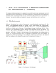
Electronics SC410 & SC412
Agilent VEE Supplement to the Laboratory Manual
By:
Moe Wasserman
College of Engineering
Boston University
Boston, Massachusetts
Equipment Required
• Agilent 34401A Digital Multimeter
• Agilent 33120A Function/Arb Generator
Introduction:
In each of the following experiments, you will "write" a program to instruct the instruments on the lab bench to perform
prescribed measurements on your circuits. In some cases your program will analyze the data received by the
instruments, and will present the results on the computer screen in graphical and/or tabular form.
The reason why the word "write" is in quotation marks is that the programming language you will use, Agilent VEE, has a
purely graphical, rather than text, interface. Conventional program statements will be replaced by objects, or icons on the
computer screen, and the order of execution of the objects will be determined by "wires" that connect the icons.
Before performing any of these experiments, you should read the introductory document, entitled Using Agilent VEE,
then work through the four exercises that you will find there.
The first step in programming any Agilent VEE-controlled experiment is to place on the screen an Panel Driver object for each
of the instruments to be used. These objects will be used to set the default configurations for the instruments; they will not be
connected by wires to anything else on the screen. Instructions for setting the defaults will be given in each experiment. The
settings will be made on the Main Panel of each object unless another panel is designated. Only the necessary settings will be
specified; all others are immaterial.
Recall that there is no instrument panel object for the triple power supply; you must use a Direct I/O object. All valid
commands for this instrument, as well as for the other instruments on your bench, will be found in the User's Manual for each
instrument. We use a Direct I/O driver here because no other driver is available, but one could be used for any of the
instruments on the bench. They respond faster than the other kinds of driver, and they can issue commands that are not
accessible from the instrument panels. These advantages come at the cost of knowing the commands for each instrument and
entering them in the appropriate sequence.
As is often the case, a program may not perform as expected on the first try. If this occurs, two useful debugging tools are
available. They can be activated with the menu commands
Debug --> Show Data Flow
and
Debug --> Show Execution Flow.
To use these to best advantage, set the slowest speed for these processes with
File --> Default Preferences on the General tab, in the Debug group, click the Data Flow Rate arrow to show the drop-down
list. Set the rate to 1(Slowest).
When the program is run, you will see symbols representing data and commands moving along the wires between objects, and
each object will be highlighted when it is active. Operating in this mode is also useful to assist you in understanding how
Agilent VEE works. But don't use these options all the time, because they slow down execution considerably.
Always begin an experiment setup by clicking the reset button on each instrument panel object. If you don't, the instrument
may not be in the proper operating mode when you run the experiment.
The following symbols will be used in the circuit schematics:
Function Generator
FG
CH1
TPS
p6V
Triple power supply
+6 volt output
A
Multimeter in
ammeter mode
TPS
p25V
Triple power supply
+25 volt output
V
Multimeter in
voltmeter mode
TPS
n25V
Triple power supply
-25 volt output
CRO
CH2
Dual-channel
oscilloscope
Instructions will be given in considerable detail for setting up and running the program for the first experiment
only. It is assumed that you will then be familiar with the basic operations of Agilent VEE.
Electronics SC410 & SC412 Experiments
Experiment No.
1
2
3
4
5
6
7
8
9
10
11
I-V Characteristics of Semiconductor Diodes
Diode Limiters
Small-Signal Behavior of the pn-Junction Diode
Transistor Curve Tracer
MOSFET Parameters
Transistor Inverters
MOSFET Transconductance
Frequency Response
Feedback Amplifiers Using Op Amps
Schmitt Trigger I
Schmitt Trigger II