1
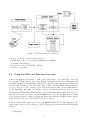
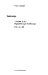
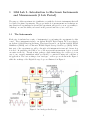
1
3050 Lab I - Introduction to Electronic Instruments
and Measurements (1 Lab Period)
The purpose of this experiment is to familiarize you with the electronic instruments that will
be required for future experiments. The proper methods of measurements and technique are
important in all experimental work and this experiment will provide you an opportunity to
’brush-up’ on some the skills you learned in the past and introduce you to new ones.
1.1
The Instruments
Each pair of students has a suite of instruments for performing the experiments for this
course. Those instruments include: an Agilent E3630A Triple Output DC Power Supply,
an Agilent 33120A Function/Arbitrary Waveform Generator, an Agilent 34401A Digital
Multimeter (DMM), and a Tektronix TDS200 Digital Storage Oscilloscope (DSO). In the
first part of the experiment we will go through each instrument in turn and discuss how
it is used. In particular, the DSO is one of the most useful measurement devices you will
encounter in the lab. Though at first perhaps a little intimidating, the oscilloscope is an
easy to use, versatile instrument which you should be comfortable using and confident of
its application. The basic workings of an “analogue” oscilloscope are shown in the Figure 1
while the workings of the Digital Storage Scope are illustrated in Figure 2.
Figure 1: An Analogue Oscilloscope.
1
Figure 2: The Digital Storage Oscilloscope.
Concepts you should learn about the DSO are:
– fundamental oscilloscope operation including use of MENUs
– grounding considerations
– the function of the AC-GND-DC coupling
– oscilloscope triggering
1.2
Using the DSO and Function Generator
Connect the Function Generator to CH1 of the DSO using a cable with BNC connectors
at both ends. First generate a sine wave having a frequency in the 10’s of kHz range and
an amplitude that is some multiple of 100 mV (see page 19 of the Agilent 33120A Function
Generator User’s Guide). Also, add a DC offset of 100 to 200 mV. On the DSO, adjust the
“sec/div” knob to see two complete cycles of the waveform on CH1. Use the CH1 menu to
set the Coupling, BW Limit, Volts/Div, Probe, and Invert values (see page 89 of the
TDS 200-Series Digital Real-Time Oscilloscope User Manual). What values did you choose
and why did you choose them? Use the TRIGGER menu to set the Trigger mode to Edge.
Set the Slope, Source, Mode and Coupling values and adjust the Trigger Level. Again,
what values did you choose and why did you choose them?
With the DSO in DC-coupled mode, select the MEASURE menu. Check what happens to the
menu display when you select Source or Type. Measure the following values using the menu
buttons.
1. Frequency
2
2. Pk-Pk Voltage
3. Mean Voltage
4. Period
Are these values consistent with the settings on your function generator? Do they change if
you change to AC coupling on the DSO?
Repeat the steps in this section for a square wave, triangular wave, and sawtooth wave.
1.3
Using the DC Power Supply and the DMM
Grab a couple of resistors from the pile provided. Record the band structure of the resistors
and measure their resistance using the DMM. [For your report: How close are they in value
to what the bands indicate they are? Is this what you would expect?] Connect the resistors
in series on a bread-board (also called a proto-board) and measure the resistance of the pair.
Now use the Power Supply to apply around 2 V DC across the pair. Draw completely how
you set up the circuit including where is the common ground point of the Power Supply.
Measure and record the potential drop across each resistor in turn using the DMM. Measure
the current through the resistors. Show exactly how you performed the measurements. What
did you expect the results to be and did you find this to be the case? Perform the voltage
measurements again using the DSO rather than the DMM.
Now remove the DC Power Supply and connect the square-wave signal from section 1.2 across
the pair of resistors. Repeat the measurements of the previous paragraph, again making sure
to show how each measurement was made. Compare the values from the MEASURE Menu on
the DSO with the measurement from the DMM. Are they consistent?
3