1
User Manual
SoftLogix 5800 System
Catalog Numbers 1789-L10, 1789-L30, 1789-L60
Important User Information
Read this document and the documents listed in the additional resources section about installation, configuration, and
operation of this equipment before you install, configure, operate, or maintain this product. Users are required to
familiarize themselves with installation and wiring instructions in addition to requirements of all applicable codes, laws,
and standards.
Activities including installation, adjustments, putting into service, use, assembly, disassembly, and maintenance are required
to be carried out by suitably trained personnel in accordance with applicable code of practice.
If this equipment is used in a manner not specified by the manufacturer, the protection provided by the equipment may be
impaired.
In no event will Rockwell Automation, Inc. be responsible or liable for indirect or consequential damages resulting from the
use or application of this equipment.
The examples and diagrams in this manual are included solely for illustrative purposes. Because of the many variables and
requirements associated with any particular installation, Rockwell Automation, Inc. cannot assume responsibility or
liability for actual use based on the examples and diagrams.
No patent liability is assumed by Rockwell Automation, Inc. with respect to use of information, circuits, equipment, or
software described in this manual.
Reproduction of the contents of this manual, in whole or in part, without written permission of Rockwell Automation,
Inc., is prohibited.
Throughout this manual, when necessary, we use notes to make you aware of safety considerations.
WARNING: Identifies information about practices or circumstances that can cause an explosion in a hazardous environment,
which may lead to personal injury or death, property damage, or economic loss.
ATTENTION: Identifies information about practices or circumstances that can lead to personal injury or death, property
damage, or economic loss. Attentions help you identify a hazard, avoid a hazard, and recognize the consequence.
IMPORTANT
Identifies information that is critical for successful application and understanding of the product.
Labels may also be on or inside the equipment to provide specific precautions.
SHOCK HAZARD: Labels may be on or inside the equipment, for example, a drive or motor, to alert people that dangerous
voltage may be present.
BURN HAZARD: Labels may be on or inside the equipment, for example, a drive or motor, to alert people that surfaces may
reach dangerous temperatures.
ARC FLASH HAZARD: Labels may be on or inside the equipment, for example, a motor control center, to alert people to
potential Arc Flash. Arc Flash will cause severe injury or death. Wear proper Personal Protective Equipment (PPE). Follow ALL
Regulatory requirements for safe work practices and for Personal Protective Equipment (PPE).
Allen-Bradley, Rockwell Software, RSLogix, FactoryTalk, SoftLogix, RSLinx, ControlLogix, Studio 5000, Rockwell Automation, SLC, PLC-5, Logix5000, PhaseManager, ControlLogix, RSNetWorx, FlexLogix, PLC-2,
PLC-3, PLC-5, DH+, Integrated Architecure, Kinetix, FLEX, PanelView, Studio 5000, and Studio 5000 Logix Designer are trademarks of Rockwell Automation, Inc.Allen-Bradley, Rockwell Software, RSLogix, FactoryTalk,
SoftLogix, RSLinx, ControlLogix, Studio 5000, Rockwell Automation, SLC, PLC-5, Logix5000, PhaseManager, ControlLogix, RSNetWorx, FlexLogix, PLC-2, PLC-3, PLC-5, DH+, Integrated Architecure, Kinetix, FLEX,
PanelView, Studio 5000, and Studio 5000 Logix Designer are trademarks of Rockwell Automation, Inc. Trademarks not belonging to Rockwell Automation are property of their respective companies.
Summary of Changes
Introduction
This document contains new and updated information. To find new and updated
information, look for change bars, as shown next to this paragraph.
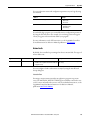
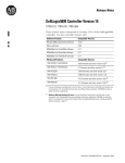
Updated Information
The document contains these changes. This table represents major topics. Make
sure to look for the change bars throughout this document.
Topic
Page
Content has been updated to reflect support of the Studio 5000 Logix Designer™ application,
version 23.
Throughout
Rockwell Automation Publication 1789-UM002K-EN-P - January 2015
3
Summary of Changes
Notes:
4
Rockwell Automation Publication 1789-UM002K-EN-P - January 2015
Table of Contents
Preface
Studio 5000 Environment . . . . . . . . . . . . . . . . . . . . . . . . . . . . . . . . . . . . . . . . 11
Additional Resources . . . . . . . . . . . . . . . . . . . . . . . . . . . . . . . . . . . . . . . . . . . . . 12
Chapter 1
SoftLogix 5800 System
About the SoftLogix 5800 Controller. . . . . . . . . . . . . . . . . . . . . . . . . . . . . .
Before You Begin . . . . . . . . . . . . . . . . . . . . . . . . . . . . . . . . . . . . . . . . . . . . . . . .
Install the SoftLogix 5800 Controller . . . . . . . . . . . . . . . . . . . . . . . . . . . . . .
FactoryTalk Activation Manager . . . . . . . . . . . . . . . . . . . . . . . . . . . . . . . . . .
Node-locked Activation. . . . . . . . . . . . . . . . . . . . . . . . . . . . . . . . . . . . . . .
Concurrent Activation. . . . . . . . . . . . . . . . . . . . . . . . . . . . . . . . . . . . . . . .
Run the FactoryTalk Activation Manager . . . . . . . . . . . . . . . . . . . . . .
Activation Tools and Rehosting . . . . . . . . . . . . . . . . . . . . . . . . . . . . . . .
Troubleshoot FactoryTalk Activations . . . . . . . . . . . . . . . . . . . . . . . . .
Configure the RSLinx Virtual-backplane Driver . . . . . . . . . . . . . . . . . . . .
13
14
15
16
16
16
16
17
18
19
Chapter 2
What is the SoftLogix System?
SoftLogix System Components. . . . . . . . . . . . . . . . . . . . . . . . . . . . . . . . . . . .
SoftLogix System Description . . . . . . . . . . . . . . . . . . . . . . . . . . . . . . . . .
Set Up the Chassis Monitor. . . . . . . . . . . . . . . . . . . . . . . . . . . . . . . . . . . . . . .
Determine a Memory Size. . . . . . . . . . . . . . . . . . . . . . . . . . . . . . . . . . . . .
Specify a Periodic Save Interval . . . . . . . . . . . . . . . . . . . . . . . . . . . . . . . .
Configure the SoftLogix Controller . . . . . . . . . . . . . . . . . . . . . . . . . . . . . . .
Step 1: Create and Configure the Controller
in the SoftLogix Chassis Monitor . . . . . . . . . . . . . . . . . . . . . . . . . . . . . .
Change the RSLinx Software Slot. . . . . . . . . . . . . . . . . . . . . . . . . . . . . .
Step 2: Create the New Controller Project
in the Logix Designer Application . . . . . . . . . . . . . . . . . . . . . . . . . . . . .
Step 3: Configure the Controller
in the Logix Designer Application Project . . . . . . . . . . . . . . . . . . . . . .
Developing Programs. . . . . . . . . . . . . . . . . . . . . . . . . . . . . . . . . . . . . . . . . . . . .
Configuring Tasks. . . . . . . . . . . . . . . . . . . . . . . . . . . . . . . . . . . . . . . . . . . .
Determining Programs. . . . . . . . . . . . . . . . . . . . . . . . . . . . . . . . . . . . . . . .
Supporting Routines. . . . . . . . . . . . . . . . . . . . . . . . . . . . . . . . . . . . . . . . . .
Instruction Execution. . . . . . . . . . . . . . . . . . . . . . . . . . . . . . . . . . . . . . . . .
How the SoftLogix System Uses Connections . . . . . . . . . . . . . . . . . . . . . .
Connections for Produced and Consumed Tags . . . . . . . . . . . . . . . . . . . .
Connections for Messages . . . . . . . . . . . . . . . . . . . . . . . . . . . . . . . . . . . . . . . .
Connections for I/O Modules . . . . . . . . . . . . . . . . . . . . . . . . . . . . . . . . . . . .
Total Connection Requirements . . . . . . . . . . . . . . . . . . . . . . . . . . . . . . . . . .
Restart the Controller . . . . . . . . . . . . . . . . . . . . . . . . . . . . . . . . . . . . . . . . . . . .
Online with the Controller. . . . . . . . . . . . . . . . . . . . . . . . . . . . . . . . . . . .
Upload to the Controller . . . . . . . . . . . . . . . . . . . . . . . . . . . . . . . . . . . . .
Select a System Overhead Percentage . . . . . . . . . . . . . . . . . . . . . . . . . . . . . .
Rockwell Automation Publication 1789-UM002K-EN-P - January 2015
22
23
24
25
26
27
27
29
31
32
34
34
36
37
37
38
38
39
40
40
41
41
41
42
5
Table of Contents
Chapter 3
Communicate with Devices on an
Ethernet Network
Configure Your System for an Ethernet Network . . . . . . . . . . . . . . . . . . .
Step 1: Disable UDP Messages in RSLinx Classic Software . . . . . . .
Disabling the UDP option. . . . . . . . . . . . . . . . . . . . . . . . . . . . . . . . . . . . .
Enabling the UDP option . . . . . . . . . . . . . . . . . . . . . . . . . . . . . . . . . . . . .
Step 2: Create the Communication Card
in the SoftLogix Chassis Monitor . . . . . . . . . . . . . . . . . . . . . . . . . . . . . .
Step 3: Configure the Communication Card
as Part of the Project . . . . . . . . . . . . . . . . . . . . . . . . . . . . . . . . . . . . . . . . . .
Step 4: Configure the SoftLogix EtherNet/IP Module to
Communicate on an Ethernet Network . . . . . . . . . . . . . . . . . . . . . . . .
Multiple EtherNet/IP Modules. . . . . . . . . . . . . . . . . . . . . . . . . . . . . . . . . . . .
Ethernet Communication . . . . . . . . . . . . . . . . . . . . . . . . . . . . . . . . . . . . .
Domain Interactions . . . . . . . . . . . . . . . . . . . . . . . . . . . . . . . . . . . . . . . . . .
Controller Connections over the EtherNet/IP Network. . . . . . . . . . . . .
Supported Functionality
of the SoftLogix 5800 EtherNet/IP Module. . . . . . . . . . . . . . . . . . . . .
Distributed Ethernet I/O . . . . . . . . . . . . . . . . . . . . . . . . . . . . . . . . . . . . . . . . .
I/O Configuration Order in the Project . . . . . . . . . . . . . . . . . . . . . . . .
Ethernet I/O Data . . . . . . . . . . . . . . . . . . . . . . . . . . . . . . . . . . . . . . . . . . . .
Add a Remote Controller . . . . . . . . . . . . . . . . . . . . . . . . . . . . . . . . . . . . . . . . .
Add a Consumed Tag . . . . . . . . . . . . . . . . . . . . . . . . . . . . . . . . . . . . . . . . .
Check EtherNet/IP Statistics. . . . . . . . . . . . . . . . . . . . . . . . . . . . . . . . . . . . . .
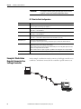
Example 1: Workstation Remotely Connected
to a SoftLogix Controller . . . . . . . . . . . . . . . . . . . . . . . . . . . . . . . . . . . . . . . . .
Example 2: Send Messages over the EtherNet/IP Network . . . . . . . . . . .
Configure a MSG Instruction. . . . . . . . . . . . . . . . . . . . . . . . . . . . . . . . . .
Example 3: Send Messages over the EtherNet/IP Network
to a PLC-5 Processor . . . . . . . . . . . . . . . . . . . . . . . . . . . . . . . . . . . . . . . . . . . . .
Configure a MSG Instruction. . . . . . . . . . . . . . . . . . . . . . . . . . . . . . . . . .
Example 4: Control Distributed I/O . . . . . . . . . . . . . . . . . . . . . . . . . . . . . . .
43
44
45
46
48
50
53
54
54
54
55
56
56
56
58
60
61
63
65
68
69
71
71
73
Chapter 4
Communicate with Serial Devices
6
Configure Your System for a Serial Device. . . . . . . . . . . . . . . . . . . . . . . . . .
Step 1: Configure the Serial Port . . . . . . . . . . . . . . . . . . . . . . . . . . . . . . .
Change the COM Port Setting . . . . . . . . . . . . . . . . . . . . . . . . . . . . . . . .
Step 2: Configure the Serial Port of the Controller in the Project .
Controller Status Indicators . . . . . . . . . . . . . . . . . . . . . . . . . . . . . . . . . . . . . . .
Example 1: Workstation Directly Connected
to a SoftLogix Controller . . . . . . . . . . . . . . . . . . . . . . . . . . . . . . . . . . . . . . . . .
DF1 Point-to-Point Configuration. . . . . . . . . . . . . . . . . . . . . . . . . . . . .
Example 2: Workstation Remotely Connected
to a SoftLogix Controller . . . . . . . . . . . . . . . . . . . . . . . . . . . . . . . . . . . . . . . . .
Master and Slave Communication Methods . . . . . . . . . . . . . . . . . . . .
DF1 Slave Configuration . . . . . . . . . . . . . . . . . . . . . . . . . . . . . . . . . . . . . .
DF1 Master Configuration . . . . . . . . . . . . . . . . . . . . . . . . . . . . . . . . . . . .
Rockwell Automation Publication 1789-UM002K-EN-P - January 2015
75
76
78
81
85
85
86
86
87
88
88
Table of Contents
Example 3: SoftLogix Controller to a Bar Code Reader . . . . . . . . . . . . . .
Connect the ASCII Device to the Controller . . . . . . . . . . . . . . . . . . .
User Mode Configuration. . . . . . . . . . . . . . . . . . . . . . . . . . . . . . . . . . . . .
ASCII Instructions . . . . . . . . . . . . . . . . . . . . . . . . . . . . . . . . . . . . . . . . . . .
90
90
91
92
Chapter 5
Configure and Use Simulated I/O
Configure Your System for a 1789-SIM Module . . . . . . . . . . . . . . . . . . . . 93
Step 1: Create the 1789-SIM Module
in the SoftLogix Chassis Monitor . . . . . . . . . . . . . . . . . . . . . . . . . . . . . . 94
Step 2: Configure the 1789-SIM module as Part of the Project . . . 97
Map I/O Data to the 1789-SIM Module . . . . . . . . . . . . . . . . . . . . . . . . . . 100
Toggle Inputs and Monitor Outputs. . . . . . . . . . . . . . . . . . . . . . . . . . . . . . 101
Turn On or Force a Bit . . . . . . . . . . . . . . . . . . . . . . . . . . . . . . . . . . . . . . 102
Example: Move Application Data into the 1789-SIM Tags . . . . . . . . . 103
Chapter 6
Execute External Routines
Configure Your System to Execute an External Routine . . . . . . . . . . . .
Add an External Routine to the Controller Organizer . . . . . . . . . . . . . .
How the Project Stores and Downloads an External Routine . . . .
Call an External Routine. . . . . . . . . . . . . . . . . . . . . . . . . . . . . . . . . . . . . . . . .
Jump to External Routine (JXR). . . . . . . . . . . . . . . . . . . . . . . . . . . . . .
Operands . . . . . . . . . . . . . . . . . . . . . . . . . . . . . . . . . . . . . . . . . . . . . . . . . . .
Description . . . . . . . . . . . . . . . . . . . . . . . . . . . . . . . . . . . . . . . . . . . . . . . . .
Arithmetic Status Flags . . . . . . . . . . . . . . . . . . . . . . . . . . . . . . . . . . . . . .
Fault Conditions . . . . . . . . . . . . . . . . . . . . . . . . . . . . . . . . . . . . . . . . . . . .
Execution. . . . . . . . . . . . . . . . . . . . . . . . . . . . . . . . . . . . . . . . . . . . . . . . . . .
Type Checking . . . . . . . . . . . . . . . . . . . . . . . . . . . . . . . . . . . . . . . . . . . . . . . . .
105
106
111
112
112
112
113
113
114
114
114
Chapter 7
Develop External Routines
Considerations For External Routines . . . . . . . . . . . . . . . . . . . . . . . . . . . .
How the SoftLogix Controller Executes External Routines . . . . . . . . .
How the Project Stores and Downloads an External Routine . . . .
Create Synchronous, Single-threaded External Routines. . . . . . . . . . . .
Create a Visual Studio Project . . . . . . . . . . . . . . . . . . . . . . . . . . . . . . . .
Project Files . . . . . . . . . . . . . . . . . . . . . . . . . . . . . . . . . . . . . . . . . . . . . . . . . . . .
RA_ExternalRoutines.h. . . . . . . . . . . . . . . . . . . . . . . . . . . . . . . . . . . . . .
InlineExample.cpp. . . . . . . . . . . . . . . . . . . . . . . . . . . . . . . . . . . . . . . . . . .
InlineExample.h. . . . . . . . . . . . . . . . . . . . . . . . . . . . . . . . . . . . . . . . . . . . .
Create an HTML Resource . . . . . . . . . . . . . . . . . . . . . . . . . . . . . . . . . . . . . .
Add Version Information to an External Routine DLL . . . . . . . . . . . . .
Build and Download External Routines . . . . . . . . . . . . . . . . . . . . . . . . . . .
Update an Existing External Routine . . . . . . . . . . . . . . . . . . . . . . . . . . . . .
Create Multi-threaded External Routines . . . . . . . . . . . . . . . . . . . . . . . . .
Sounds.cpp . . . . . . . . . . . . . . . . . . . . . . . . . . . . . . . . . . . . . . . . . . . . . . . . .
Thread Priorities in a Multithreaded External Routine DLL . . . .
Debug External Routines . . . . . . . . . . . . . . . . . . . . . . . . . . . . . . . . . . . . . . . .
Rockwell Automation Publication 1789-UM002K-EN-P - January 2015
115
116
117
117
117
118
119
121
122
123
128
130
130
130
131
135
136
7
Table of Contents
Set Up the Debug Session . . . . . . . . . . . . . . . . . . . . . . . . . . . . . . . . . . . .
Start a Debug Session . . . . . . . . . . . . . . . . . . . . . . . . . . . . . . . . . . . . . . . .
Set Breakpoints in External Routine Code . . . . . . . . . . . . . . . . . . . . .
Data Type Support . . . . . . . . . . . . . . . . . . . . . . . . . . . . . . . . . . . . . . . . . . . . . .
ARRAY Example . . . . . . . . . . . . . . . . . . . . . . . . . . . . . . . . . . . . . . . . . . . .
INTEGER Example . . . . . . . . . . . . . . . . . . . . . . . . . . . . . . . . . . . . . . . . .
STRUCTURE Example . . . . . . . . . . . . . . . . . . . . . . . . . . . . . . . . . . . . .
STRING Example . . . . . . . . . . . . . . . . . . . . . . . . . . . . . . . . . . . . . . . . . . .
Packing in Structures. . . . . . . . . . . . . . . . . . . . . . . . . . . . . . . . . . . . . . . . .
Parameter Type Checking . . . . . . . . . . . . . . . . . . . . . . . . . . . . . . . . . . . .
Return Parameter. . . . . . . . . . . . . . . . . . . . . . . . . . . . . . . . . . . . . . . . . . . .
Export Functions by Using C++ Export Style . . . . . . . . . . . . . . . . . . . . .
InlineExample.h . . . . . . . . . . . . . . . . . . . . . . . . . . . . . . . . . . . . . . . . . . . . .
InlineExample.cpp . . . . . . . . . . . . . . . . . . . . . . . . . . . . . . . . . . . . . . . . . . .
Run dumpbin.exe. . . . . . . . . . . . . . . . . . . . . . . . . . . . . . . . . . . . . . . . . . . .
Edit XML Resource. . . . . . . . . . . . . . . . . . . . . . . . . . . . . . . . . . . . . . . . . .
Other Considerations . . . . . . . . . . . . . . . . . . . . . . . . . . . . . . . . . . . . . . . . . . .
Pass Tags by Reference . . . . . . . . . . . . . . . . . . . . . . . . . . . . . . . . . . . . . . .
External Routine DLL that Uses Other DLLs. . . . . . . . . . . . . . . . . .
136
137
138
138
139
140
141
142
143
144
144
145
145
145
145
146
147
147
147
Chapter 8
Program Windows Events to Monitor Use Outbound Events . . . . . . . . . . . . . . . . . . . . . . . . . . . . . . . . . . . . . . . . . . . 149
Programming Example: Outbound Events . . . . . . . . . . . . . . . . . . . . . 150
and Change Controller Execution
Configure Windows Events to Launch Tasks
within the SoftLogix Controller . . . . . . . . . . . . . . . . . . . . . . . . . . . . . . . . . .
Configure a Windows-event Task in the Controller . . . . . . . . . . . .
Trigger a Controller Task from a Windows Application . . . . . . . .
Programming Example: Windows Event. . . . . . . . . . . . . . . . . . . . . . .
Programmatically Saving the Controller . . . . . . . . . . . . . . . . . . . . . . . . . . .
Programming Example: Programmatic Save of Controller . . . . . . .
153
153
156
156
158
158
Appendix A
Communicate with Devices on a
DeviceNet Network
8
Configure Your System for a DeviceNet Network. . . . . . . . . . . . . . . . . .
Step 1: Install the Hardware . . . . . . . . . . . . . . . . . . . . . . . . . . . . . . . . . .
Step 2: Create the Communication Card
in the SoftLogix Chassis Monitor . . . . . . . . . . . . . . . . . . . . . . . . . . . . .
Step 3: Install the Communication Driver . . . . . . . . . . . . . . . . . . . . .
Step 4: Configure the Communication Card
as Part of the Project . . . . . . . . . . . . . . . . . . . . . . . . . . . . . . . . . . . . . . . . .
Step 5: Download the Project to the Controller . . . . . . . . . . . . . . . .
Step 6: Define the Scanlist . . . . . . . . . . . . . . . . . . . . . . . . . . . . . . . . . . . .
Perform DeviceNet Test . . . . . . . . . . . . . . . . . . . . . . . . . . . . . . . . . . . . . . . . .
Step 1: Start the Test Application . . . . . . . . . . . . . . . . . . . . . . . . . . . . .
Step 2: Configure the Port. . . . . . . . . . . . . . . . . . . . . . . . . . . . . . . . . . . .
Step 3: Create a View . . . . . . . . . . . . . . . . . . . . . . . . . . . . . . . . . . . . . . . .
Step 4: Read Inputs and Write Outputs . . . . . . . . . . . . . . . . . . . . . . .
Rockwell Automation Publication 1789-UM002K-EN-P - January 2015
162
162
163
166
169
171
172
181
181
182
184
186
Table of Contents
Step 5: Change the Scanner Mode . . . . . . . . . . . . . . . . . . . . . . . . . . . .
DeviceNet I/O Data . . . . . . . . . . . . . . . . . . . . . . . . . . . . . . . . . . . . . . . . . . . .
Determine How Often to Update Data . . . . . . . . . . . . . . . . . . . . . . .
Place the Communication Card in Run Mode . . . . . . . . . . . . . . . . . . . . .
CommandRegister Bits . . . . . . . . . . . . . . . . . . . . . . . . . . . . . . . . . . . . . .
StatusRegister. . . . . . . . . . . . . . . . . . . . . . . . . . . . . . . . . . . . . . . . . . . . . . . . . . .
Status Data Elements . . . . . . . . . . . . . . . . . . . . . . . . . . . . . . . . . . . . . . . .
Example: SoftLogix Controller and DeviceNet I/O . . . . . . . . . . . . . . . .
Create Alias Tags. . . . . . . . . . . . . . . . . . . . . . . . . . . . . . . . . . . . . . . . . . . .
187
188
189
190
190
191
192
193
194
Appendix B
Communicate with Devices on a
ControlNet Network
Configure Your System for a ControlNet Network . . . . . . . . . . . . . . . .
Step 1: Install the Hardware . . . . . . . . . . . . . . . . . . . . . . . . . . . . . . . . . .
Step 2: Create the Communication Card
in the SoftLogix Chassis Monitor . . . . . . . . . . . . . . . . . . . . . . . . . . . . .
Step 3: Configure the Communication Card
as Part of the Project . . . . . . . . . . . . . . . . . . . . . . . . . . . . . . . . . . . . . . . . .
Step 4: Add Remote Communication Devices
for the Communication Card . . . . . . . . . . . . . . . . . . . . . . . . . . . . . . . .
Step 5: Download the Project to the Controller . . . . . . . . . . . . . . . .
Step 6: Schedule the Network . . . . . . . . . . . . . . . . . . . . . . . . . . . . . . . .
ControlNet I/O Data . . . . . . . . . . . . . . . . . . . . . . . . . . . . . . . . . . . . . . . . . . .
Rack-optimized Connections. . . . . . . . . . . . . . . . . . . . . . . . . . . . . . . . .
Direct Connections . . . . . . . . . . . . . . . . . . . . . . . . . . . . . . . . . . . . . . . . .
Example 1: SoftLogix Controller and ControlNet I/O . . . . . . . . . . . . .
Controlling I/O Modules . . . . . . . . . . . . . . . . . . . . . . . . . . . . . . . . . . . .
Total Connections Required by the SoftLogix Controller. . . . . . .
Example 2: SoftLogix Controller to SoftLogix Controller . . . . . . . . . .
Send a MSG Instruction . . . . . . . . . . . . . . . . . . . . . . . . . . . . . . . . . . . . .
Produce and Consume Tags . . . . . . . . . . . . . . . . . . . . . . . . . . . . . . . . . .
Total Connections Required by the Soft1 Controller. . . . . . . . . . .
Example 3: SoftLogix Controller to Other Devices. . . . . . . . . . . . . . . . .
Send a MSG Instruction . . . . . . . . . . . . . . . . . . . . . . . . . . . . . . . . . . . . .
Produce and Consume Tags . . . . . . . . . . . . . . . . . . . . . . . . . . . . . . . . . .
Total Connections Required by the Soft1 Controller. . . . . . . . . . .
Example 4: Use the SoftLogix Controller as a Gateway . . . . . . . . . . . . .
195
196
197
200
204
211
213
219
220
221
222
222
222
223
224
225
228
228
229
230
233
234
Appendix C
Program Virtual Motion
Virtual Motion Overview . . . . . . . . . . . . . . . . . . . . . . . . . . . . . . . . . . . . . . . .
Logic for Motion Control . . . . . . . . . . . . . . . . . . . . . . . . . . . . . . . . . . . . . . .
Motion Faults. . . . . . . . . . . . . . . . . . . . . . . . . . . . . . . . . . . . . . . . . . . . . . .
Considerations When Running a Motion Application
in Windows Operating System . . . . . . . . . . . . . . . . . . . . . . . . . . . . . . . . . . .
237
238
239
240
Appendix D
Windows Considerations
Observe Windows Objects. . . . . . . . . . . . . . . . . . . . . . . . . . . . . . . . . . . . . . . 241
Rockwell Automation Publication 1789-UM002K-EN-P - January 2015
9
Table of Contents
Additional Considerations . . . . . . . . . . . . . . . . . . . . . . . . . . . . . . . . . . . . . . .
Run a SoftLogix Controller on the Windows Operating System . . . . .
Dwell Time Setting . . . . . . . . . . . . . . . . . . . . . . . . . . . . . . . . . . . . . . . . . .
Periodic Tasks . . . . . . . . . . . . . . . . . . . . . . . . . . . . . . . . . . . . . . . . . . . . . . .
System Overhead Timeslice. . . . . . . . . . . . . . . . . . . . . . . . . . . . . . . . . . .
Multiple SoftLogix Controllers in the Virtual Chassis . . . . . . . . . .
HMI Considerations . . . . . . . . . . . . . . . . . . . . . . . . . . . . . . . . . . . . . . . . . . . .
Personal Computer Hardware Considerations . . . . . . . . . . . . . . . . . . . . .
242
243
243
244
247
247
247
248
Appendix E
System Performance Tuning
Guidelines
Pre-qualify Your Personal Computer for Soft Control . . . . . . . . . . . . . .
System Performance . . . . . . . . . . . . . . . . . . . . . . . . . . . . . . . . . . . . . . . . . . . . .
System Startup . . . . . . . . . . . . . . . . . . . . . . . . . . . . . . . . . . . . . . . . . . . . . . . . . .
Monitor Personal Computer Performance. . . . . . . . . . . . . . . . . . . . . . . . .
249
252
253
253
Appendix F
Status Indicators
SoftLogix Controller Status Indicators . . . . . . . . . . . . . . . . . . . . . . . . . . . .
Controller Status Indicator and Display . . . . . . . . . . . . . . . . . . . . . . .
SoftLogix EtherNet/IP Module Status Indicators . . . . . . . . . . . . . . . . . .
Link Status (LINK) Indicator . . . . . . . . . . . . . . . . . . . . . . . . . . . . . . . .
Network Status (NET) Indicator . . . . . . . . . . . . . . . . . . . . . . . . . . . . .
Module Status (OK) Indicator. . . . . . . . . . . . . . . . . . . . . . . . . . . . . . . .
257
258
259
259
260
260
Appendix G
SoftLogix 5800 Revision History
SoftLogix 5800 Version 23 . . . . . . . . . . . . . . . . . . . . . . . . . . . . . . . . . . . . . . . 261
SoftLogix 5800 Version 21 . . . . . . . . . . . . . . . . . . . . . . . . . . . . . . . . . . . . . . . 261
SoftLogix 5800 Version 20 . . . . . . . . . . . . . . . . . . . . . . . . . . . . . . . . . . . . . . . 261
Index
10
Rockwell Automation Publication 1789-UM002K-EN-P - January 2015
Preface
Use this manual to become familiar with the SoftLogix™ 5800 controller and its
features.
Studio 5000 Environment
The Studio 5000 Engineering and Design Environment™ combines engineering
and design elements into a common environment. The first element in the Studio
5000® environment is the Logix Designer application. The Logix Designer
application is the rebranding of RSLogix™ 5000 software and will continue to be
the product to program Logix5000™ controllers for discrete, process, batch,
motion, safety, and drive-based solutions.
The Studio 5000 environment is the foundation for the future of Rockwell
Automation® engineering design tools and capabilities. It is the one place for
design engineers to develop all of the elements of their control system.
This manual is written to support SoftLogix software version 23.00.00 and the
Logix Designer application. For SoftLogix software version 21 or earlier,
substitute ‘RSLogix 5000 software’ for ‘the Logix Designer application’.
Rockwell Automation Publication 1789-UM002K-EN-P - January 2015
11
Preface
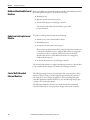
Additional Resources
These documents address the Logix5000 family of controllers and networks.
IMPORTANT
We recommend that you read the appropriate release notes for software
requirements, compatible PCI cards and driver, and system requirements.
To locate the release notes for your system, search for 1789-RN in the Rockwell
Automation Literature Library, http:/www.literature.rockwellautomation.com.
Resource
Description
Logix5000 Controllers Quick Start, publication 1756-QS001
Explains how to set up a Logix5000 controller.
Logix5000 Controllers Common Procedures,
publication 1756-PM001
Describes how to complete standard tasks for
Logix5000 controllers. Program logic by using
sequential function chart (SFC), ladder diagram (LD),
structured text (ST), and function block diagram (FBD)
languages.
Logix5000 Controllers General Instruction Set Reference
Manual, publication 1756-RM003
Program sequential applications, ladder diagram, and
structured text instructions.
Logix5000 Controllers Process Control/Drives Instruction Set
Reference Manual, publication 1756-RM006
Programming process control and drives applications
and function block diagram instructions.
Logix5000 Controllers Motion Instructions Reference
Manual, publication Motion-RM002
Describes ladder diagram motion instructions so you
can program motion applications.
SERCOS and Analog Motion Configuration and Startup,
publication MOTION-UM001
Provides general information about motion modules.
EtherNet/IP Network Configuration User Manual, publication
ENET-UM001
Describes how to use EtherNet/IP communication
modules with your Logix5000 controller and
communicate with various devices on the Ethernet
network.
PhaseManager™ User Manual, publication LOGIX-UM001
Describes how to set up a state model for your
controller.
You can view or download publications at
http:/www.literature.rockwellautomation.com. To order paper copies of
technical documentation, contact your local Allen-Bradley distributor or
Rockwell Automation sales representative.
12
Rockwell Automation Publication 1789-UM002K-EN-P - January 2015
Chapter
1
SoftLogix 5800 System
Catalog Numbers 1789-L10, 1789-L30, 1789-L60
About the SoftLogix 5800
Controller
Topic
Page
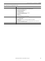
About the SoftLogix 5800 Controller
13
Before You Begin
14
Install the SoftLogix 5800 Controller
15
FactoryTalk Activation Manager
16
Configure the RSLinx Virtual-backplane Driver
19
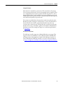
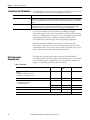
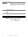
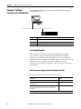
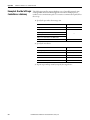
The SoftLogix™ 5800 controller you use determines how many slots are available
in the virtual chassis and how many devices you can install.
Controller
Maximum
Available Slots
1789-L10
•
•
•
•
•
One SoftLogix 5800 controller
Memory size limit of 2 MB per controller
One 1784-SIM module
EtherNet/IP support
No third-party virtual-backplane module support
3-slot virtual chassis(1)
1789-L30
•
•
•
•
•
•
Two SoftLogix 5800 controllers
Memory size limit of 64 MB per controller
Five PCI network interface cards(2)
Five 1784-SIM modules
EtherNet/IP support
Third-party virtual-backplane module support
5-slot virtual chassis
1789-L60
•
•
•
•
•
•
Six SoftLogix 5800 controllers
Memory size limit of 64 MB per controller
Sixteen PCI network interface cards(2)
Sixteen 1784-SIM modules
EtherNet/IP support
Third-party virtual-backplane module support
16-slot virtual chassis
(1) As of version 12 of the SoftLogix 5800 controller, the 1789-L10 controller supports three slots in the virtual
chassis.
(2) The number of available slots in the virtual chassis is limited by the controller. You can have as many PCI
communication cards as you have available slots in the virtual chassis and in the personal computer.
Rockwell Automation Publication 1789-UM002K-EN-P - January 2015
13
Chapter 1
SoftLogix 5800 System
IMPORTANT
Before You Begin
• Motion control is not supported in SoftLogix software version 20.00.00
and later.
• ControlNet,and DeviceNet modules are not supported in SoftLogix
software version 21.00.00 or later.
• SoftLogix software version 21.00.00 and later runs on these Windows
operating systems:
- Windows 7 Pro (32- and 64-bit)
- Windows 7 Home Premium (32- and 64- bit)
- Windows Server 2008 R2 Standard Edition with SP1
• For system requirements of earlier versions of SoftLogix software, see the
corresponding release notes.
• Running the SoftLogix software in a Virtual Machine (for example,
VMWare or VirtualBox), is not supported.
• SoftLogix 5800 controllers and software do not support Integrated Motion
on the EtherNet/IP network. SoftLogix software version 20.00.00 and
later does not support any motion PCI cards.
• No PCI-based cards are supported when using the Microsoft Windows 7
operating system.
• The 1784-PCIDS card is not supported when using the Microsoft Windows
2008 Server operating system.
Make sure you have the following software installed before you install
SoftLogix software:
• Microsoft Windows 7 or Windows 2008 Server operating system
• RSLinx® Classic software
IMPORTANT
We recommend that you read the appropriate release notes for system and
software requirements, compatible PCI cards and driver, and system
requirements. To locate the release notes for your system, search for 1789-RN
in the Rockwell Automation Literature Library
at http://www.rockwellautomation.com/literature.
IMPORTANT
In Microsoft Windows Vista, Windows 7, and Windows Server 2008 operating
systems, when RSLinx software is running as a service, the RSLinx driver
configuration GUI is not available.
To invoke the RSLinx GUI, remove all SoftLogix controllers from the chassis
monitor and use the RSLinx Control Panel to start RSLinx software as an
application instead of a service.
Before you can install the SoftLogix 5800 controller, perform the following steps.
14
Rockwell Automation Publication 1789-UM002K-EN-P - January 2015
SoftLogix 5800 System
Chapter 1
1. Log into the Windows operating system under an account that is a
member of the Administrators user group on the computer where you are
installing the SoftLogix 5800 controller.
To log in as a member of the Administrators group, your user account must
be added to the Administrators group on the computer. Ask your system
administrator if you need help.
2. Verify that the Windows Workstation and Server services required by the
SoftLogix 5800 controller are running. The Workstation and Server
services are automatically installed when you install Windows Networking
or Remote Access Service (RAS).
Install the SoftLogix 5800
Controller
IMPORTANT
A machine running SoftLogix software does not support a remote desktop.
IMPORTANT
If you have a previous version of SoftLogix software already installed on the computer, use
Start>Control Panel>Programs and Features to remove the earlier version before installing the
current version.
When you insert the installation DVD into your DVD ROM drive, the DVD
automatically begins the set-up program for the controller. If your computer
meets the hardware and software requirements for the controller, you can install
the controller.
1. If RSLinx software is already running, shut it down before beginning this
installation procedure.
2. Insert the SoftLogix 5800 installation DVD.
3. From the installation window, click SoftLogix 5800 V23.00.
4. Follow the set-up wizard.
Rockwell Automation Publication 1789-UM002K-EN-P - January 2015
15
Chapter 1
SoftLogix 5800 System
FactoryTalk Activation
Manager
There are two types of FactoryTalk® activations to activate the SoftLogix 5800
controller license—node-locked and concurrent.
Node-locked Activation
Node-locked activation can be used only on the computer where the activation is
locked (that is, on the personal computer for which the license was purchased).
The activation is always locked to a specific piece of hardware, for example, an
Ethernet card, a hard disk, or a USB dongle.
Concurrent Activation
Concurrent activation is used in a server-client environment. This type of
activation lets multiple computers across a network use Rockwell Automation
software products concurrently. A concurrent activation can ‘float’ to, or be
borrowed temporarily from, an activation server for a specific period of time
before expiring and returning automatically to the pool of available activations on
the server. Concurrent activations can be borrowed only if your Rockwell
Software® product supports borrowed activations.
If you want to check out a concurrent activation from an activation server, you do
not need to use the Rockwell Software Activation website. You can use the
FactoryTalk Activation Manager to configure your client computer to recognize
the activation server computer where concurrent activations are stored.
Run the FactoryTalk Activation Manager
When you install the Studio 5000 environment, FactoryTalk Activation Manager
is automatically installed on the computer where the activation needs to reside.
The FactoryTalk Activation Manager software manages activations for the
Rockwell Software products installed on the computer. The FactoryTalk
Activation Manager opens automatically when you install a new Rockwell
Software product.
You can also run the Activation Manaager from the Windows Start menu by
choosing Start>Programs>Rockwell Software>FactoryTalk
Activation>FactoryTalk Activation Manager.
For more information about the FactoryTalk Activation Manager, refer to the
online help in the software.
16
Rockwell Automation Publication 1789-UM002K-EN-P - January 2015
SoftLogix 5800 System
Chapter 1
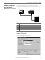
To activate your license, you need to have the host ID, serial number, and product
key information available
Item
Description
Host ID
This is found by using the FactoryTalk Activation
Manager. Choose Start>Programs>Rockwell
Software>FactoryTalk Activation>FactoryTalk.
Serial Number
This is a 10-digit number supplied to you when you
purchased your product.
Product Key
This is usually found in a red envelope that is shipped
with your product.
To start activation, follow these steps:
1. Click ‘Find Available Activations’ or ‘Get New Activations’.
2. Follow steps 1…5 in the FactoryTalk Activation Manager.
Activation Tools and Rehosting
For information on Activation Tools and Rehosting Activations, see the
Rockwell Software Activation website
at https://activate.rockwellautomation.com.
Rockwell Automation Publication 1789-UM002K-EN-P - January 2015
17
Chapter 1
SoftLogix 5800 System
Troubleshoot FactoryTalk Activations
There could be several reasons you might have trouble installing
your activations:
• If you accidentally requested too few concurrent activations for a product,
you can download more new activations for the same Host ID. You cannot
download more activations than you have purchased.
• To purchase additional activations, contact your local Rockwell
Automation sales office.
• If you accidentally requested too many concurrent activations for a
product, you must rehost all of the activations, and then request the
correct number of activations again.
• For example, if you have 50 concurrent activations available for a product,
and you intended to request 10 for a particular Host ID, but accidentally
selected 13 in the Activations Requested list, you cannot return just the
three activations you didn't want. You must rehost all 13 activations, and
then download 10 activations to the correct Host ID.
• If you accidentally requested activations for the wrong Host ID
(computer or dongle), you must rehost all of the activations you
downloaded accidentally, and then request the activations again for the
correct Host ID.
• If you accidentally requested activations for the wrong product, you must
rehost all of the activations for that product, and then request the
activations again.
• For example, if you accidentally requested five concurrent activations for
Logix Designer application instead of FactoryTalk View SE software, you
must rehost the five activations for Logix Designer application, and then
download five activations for FactoryTalk View SE software.
To obtain more information, go to the Rockwell Automation Activations
Support website at https://activate.rockwellautomation.com.
18
Rockwell Automation Publication 1789-UM002K-EN-P - January 2015
SoftLogix 5800 System
Configure the RSLinx Virtualbackplane Driver
Chapter 1
Use RSLinx software to configure the virtual-backplane driver. You do this only
once for the computer.
IMPORTANT
The RSLinx virtual-backplane driver is required for SoftLogix software
to operate.
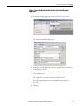
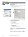
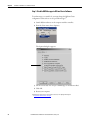
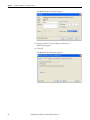
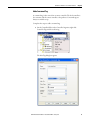
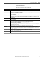
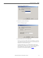
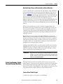
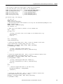
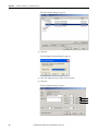
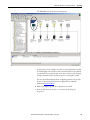
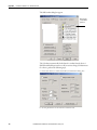
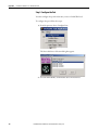
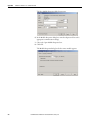
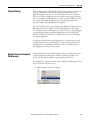
To install the virtual-backplane driver, follow these steps.
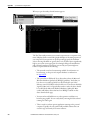
1. In RSLinx software, from the Communications menu, choose Configure
Drivers.
2. From the Available Driver Type pull-down menu, choose Virtual
Backplane Driver.
3. Click Add New.
4. Type the driver name, such as AB_VBP-1, and click OK.
The Configure Drivers dialog box appears.
Rockwell Automation Publication 1789-UM002K-EN-P - January 2015
19
Chapter 1
SoftLogix 5800 System
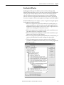
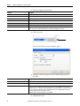
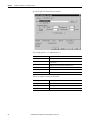
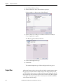
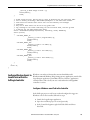
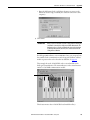
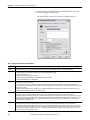
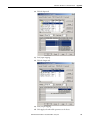
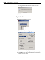
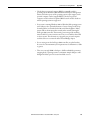
5. Click Configure.
The Configure VirtualBackplane dialog box appears. The Logix Designer
application, version 23.00.00, lets you insert a valid SoftLogix module into
slot 0.
The RSLinx software module defaults in Slot 0 if not set up for another
slot position.
6. From the Slot Number pull-down menu, choose a slot number.
7. Click OK and then click Close.
IMPORTANT
20
Even if you remotely program the controller over a ControlNet or Ethernet
link, you must add the virtual-backplane driver via RSLinx software. If you
do not, the SoftLogix application will not be restored when you restart the
computer.
Rockwell Automation Publication 1789-UM002K-EN-P - January 2015
Chapter
2
What is the SoftLogix System?
Topic
Page
SoftLogix System Components
22
Set Up the Chassis Monitor
24
Configure the SoftLogix Controller
27
Developing Programs
34
How the SoftLogix System Uses Connections
38
Connections for Produced and Consumed Tags
38
Connections for Messages
39
Connections for I/O Modules
40
Total Connection Requirements
40
Restart the Controller
41
Select a System Overhead Percentage
42
This chapter discusses SoftLogix controller options and characteristics.
Procedures include how to configure your SoftLogix controller in the virtual
chassis monitor for the first time and how to create your SoftLogix project in the
Logix Designer application.
The SoftLogix system is a ‘soft’ control system that runs in Microsoft operating
systems. The system resides on a computer, as opposed to a physical module in a
hard chassis. For a list of the supported Windows operating systems, see the
System Requirements section of the current release notes. The SoftLogix
controller is part of the Logix environment and is a software-based controller that
supports Logix instructions.
Rockwell Automation Publication 1789-UM002K-EN-P - January 2015
21
Chapter 2
What is the SoftLogix System?
SoftLogix System
Components
A SoftLogix system can have these features, depending on the version of
SoftLogix software. See chapter 1, Installation, and the Release Note for your
version of SoftLogix software for specific information about which features are
supported.
• The Chassis Monitor resides in the SoftLogix Virtual Chassis. It is a virtual
‘soft’ chassis as opposed to a physical chassis. It lets you create, delete,
monitor, and configure controllers, communication interface cards, and
motion cards in your SoftLogix system.
• The Studio 5000 environment supports every Logix controller. It provides
the flexibility to program (online or offline) in ladder logic, function block
diagram, structured text, and sequential function chart. It provides
complete axis configuration and motion programming support.
• A SoftLogix 5800 controller is based on the Logix platform and takes
control functions normally found in a dedicated programmable controller,
encapsulates them in software, and runs them on a commercial operating
system.
• The SoftLogix 5800 controller (version 19 and earlier) contains a highspeed motion task, which executes ladder motion commands and
generates position and velocity profile information. The controller sends
this profile information to one or more motion cards. Each controller can
control up to 32 axes of motion.
• There are several controllers to choose from in the SoftLogix family,
depending on your needs.
• SoftLogix software uses a commercially available Ethernet port for
messaging and controlling I/O over an EtherNet/IP network.
• RSNetWorx™ software is a configuration tool that lets you control and
schedule your network. RSNetWorx software can be used with a
ControlNet network, a DeviceNet network, and an EtherNet/IP network.
• RSLinx software is a communication server that lets you configure
communication devices for networks.
• IOLinx software lets the SoftLogix 5800 controller read I/O data.
22
Rockwell Automation Publication 1789-UM002K-EN-P - January 2015
What is the SoftLogix System?
Chapter 2
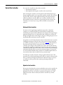
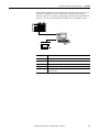
SoftLogix System Description
The Logix Designer application supports program development for all Logix
controllers. The system can make a connection through a 1784-PCICS card via
the ControlNet network, through a 1784-PCIDS card via the DeviceNet
network, and through a standard Ethernet port via the EtherNet/IP network.
SoftLogix software supports two types of motion cards; the 1784-PM02AE
analog motion card and the 1784-PM16SE SERCOS motion card. See the
release notes for your version of SoftLogix software to learn what features are
supported.
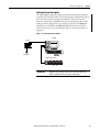
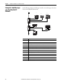
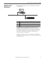
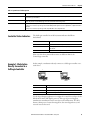
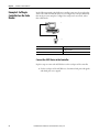
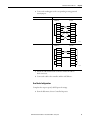
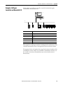
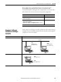
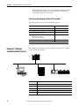
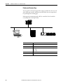
Figure 1 - The SoftLogix System at a Glance
SoftLogix
Analog
Analog Drives
EtherNet/IP Connection
IMPORTANT
Regardless of the product you have, choose 1789-L60/A in the Logix
Designer application when you specify a controller type.
Rockwell Automation Publication 1789-UM002K-EN-P - January 2015
23
Chapter 2
What is the SoftLogix System?
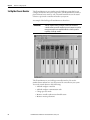
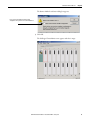
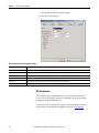
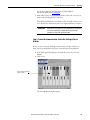
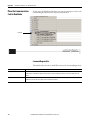
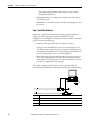
Set Up the Chassis Monitor
The Chassis Monitor is your window into the SoftLogix system that lets you
configure and monitor the system components. The Chassis Monitor models a
physical chassis, but is virtual, or ‘soft.’ You install virtual devices in the virtual
chassis to represent the controller and cards in your system.
An example of the SoftLogix Chassis Monitor is shown here.
IMPORTANT
Treat the computer running a SoftLogix controller like an industrial
controller and not a personal computer. A personal computer can perform
many operations that are incompatible with the real-time operations
required by a SoftLogix controller.
The Chassis Monitor is your SoftLogix controller interface. You use the
simulated status indicators to view the status of the controllers in your system.
You use the virtual chassis to do the following:
• Add and configure controllers
• Add and configure communication cards
• Change processor mode
• Monitor controller and associated module status
• Monitor motion performance
24
Rockwell Automation Publication 1789-UM002K-EN-P - January 2015
What is the SoftLogix System?
Chapter 2
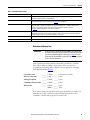
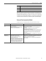
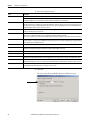
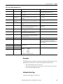
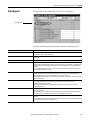
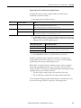
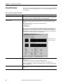
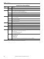
Table 1 - Chassis Motor Characteristic
Characteristic
Description
Startup mode
Specify how the controller should behave when its service is started.
Select Remote Program (default) or Last Controller State.
Memory size
Specify the memory size (KB) to allow for the controller.
The maximum limit depends on the controller type. See page 25 for more information.
Periodic save interval
Specify whether you want to save the current controller information (tag data values and configuration information)
periodically, and if so, specify how often (minutes). Specify an interval between 0.5…30 minutes. Online edits to the
program are saved instantly, regardless of Periodic Save interval. The default is enabled for 10 minutes.
See page 26 about this setting’s impact on overall system performance.
Continuous task dwell time (ms)
Specify the dwell time (0…1000 ms) made available for all other Windows applications. The default is 10 ms.
The dwell time is the time between the end of the continuous task and the start of the next execution of the continuous
task. This setting has an impact on overall system performance, see Appendix E.
CPU affinity
If your computer has multiple Pentium CPUs, choose which CPU to use for this controller. The default is CPU 0.
Channel 0 serial port
Choose which COM port to use for serial communication. Choose COM1, COM2, COM3, or COM4. The default is none.
Determine a Memory Size
IMPORTANT
The memory size you specify is the amount of RAM in your computer that
you want to allocate to the SoftLogix controller. The maximum memory size
per controller is determined by the controller type.; see page 25 for more
information. This allocated RAM is not available to the Windows operating
system or any other application.
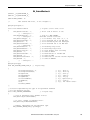
These equations provide an estimate of the memory needed for a controller.
Each of these numbers includes a rough estimate of the associated user
programming. Depending on the complexity of your application, you might
need additional memory.page 22
Controller tasks
_____ * 4000 = _____ bytes (min 1 needed)
Discrete I/O points
_____ * 400 = _____ bytes
Analog I/O points
_____ * 2600 = _____ bytes
Communication modules _____ * 2000 = _____ bytes
Motion axis
_____ * 8000 = _____ bytes
Total = _____ bytes
If you want to change the amount of memory you specified for a controller, you
must first remove the controller from the SoftLogix chassis monitor, then
reinstall the controller and specify the new memory size.
Rockwell Automation Publication 1789-UM002K-EN-P - January 2015
25
Chapter 2
What is the SoftLogix System?
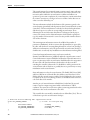
Specify a Periodic Save Interval
The periodic save task executes at a priority of ‘user-mode high’. This means that
the control process running within the SoftLogix 5800 controller will not be
impacted by a periodic save, but other user applications will be impacted if they
run at a priority lower than ‘user-mode high’. Most HMI applications run at a
‘user-mode normal’ priority. If these applications run on the same computer as
the SoftLogix 5800 controller, these applications will be starved of CPU cycles
while the periodic save is in progress. If you run an HMI application remotely
and gather data from a SoftLogix 5800 controller via OPC, the performance of
the HMI may also be impacted during a periodic save. The controller handles
both the periodic save ‘tag value upload’ and HMI OPC requests through the
same communication mechanism.
When the periodic save task executes, it performs these actions:
• For every tag defined within the controller, the current tag value is read
from the controller.
The larger the amount of data, the longer the periodic save takes and the
greater the impact on HMI responsiveness.
• The current tag values read earlier, along with the current program file, are
saved to the computer disk drive.
The larger the archive file, the longer the periodic save takes and the
greater the impact on HMI responsiveness. However, tag data size has
more of an impact than archive file size.
To maintain better HMI responsiveness, you can do the following:
• Turn off the periodic save interval.
Even with the periodic save interval disabled, a periodic save occurs if a
remote terminal performs an upload. This makes sure that the most
current tag data values and archive file are uploaded.
If you disable the periodic save, you can still initiate a save manually by
using the Save menu item on the controller from the Chassis Monitor or
programmatically from an external routine or application. (See Chapter 7).
• Increase the periodic save interval so that it occurs less frequently.
• Use a dual CPU computer.
On a dual CPU computer, the Windows operating system automatically
balances the periodic save and HMI applications across the CPUs.
For more information on system tuning and the periodic save interval,
see Appendix E.
26
Rockwell Automation Publication 1789-UM002K-EN-P - January 2015
What is the SoftLogix System?
Configure the SoftLogix
Controller
Chapter 2
You must first create and configure your SoftLogix 5800 controller, that is,
catalog number 1789-L10, 1789-L30, or 1789-L60, in the virtual chassis
monitor.
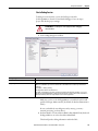
Step 1: Create and Configure the Controller in the SoftLogix Chassis
Monitor
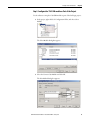
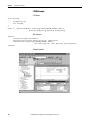
When you install a controller, the Chassis Monitor lets you configure specific
characteristics about the controller. To configure the controller in the Chassis
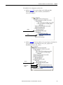
Monitor, follow these steps.
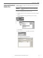
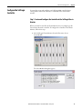
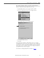
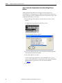
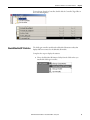
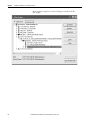
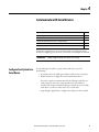
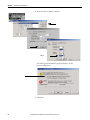
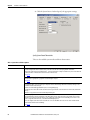
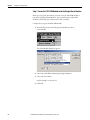
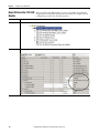
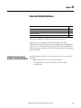
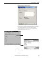
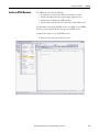
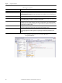
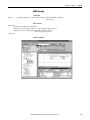
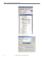
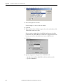
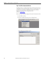
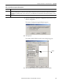
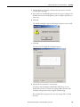
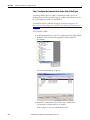
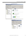
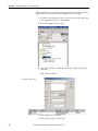
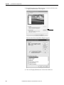
1. In the SoftLogix Chassis Monitor, from the Slot menu, choose
Create Module.
The Select Module dialog box appears.
Rockwell Automation Publication 1789-UM002K-EN-P - January 2015
27
Chapter 2
What is the SoftLogix System?
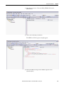
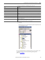
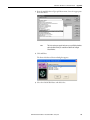
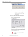
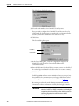
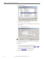
2. In the Select Module dialog box, select your module type and enter the
Slot number.
RSLinx software defaults to slot 0, but you can move it to another slot if
set up for this functionality. See page 29.
For this example, we will enter slot 1 for the 1789-L60
SoftLogix 5800 controller.
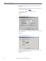
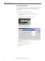
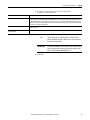
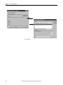
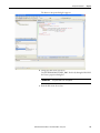
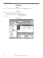
3. Click OK.
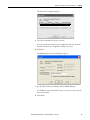
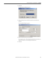
The General dialog box appears.
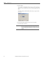
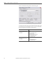
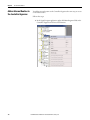
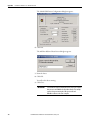
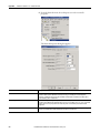
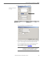
4. In the General dialog box, enter Startup Mode, Memory Size and Periodic
Save Interval values.
5. Click Next.
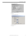
The NT System dialog box appears.
6. In the NT System dialog box, enter Continuous Task Dwell Time, CPU
Affinity, and Channel Serial Port values.
7. Click Finish.
28
Rockwell Automation Publication 1789-UM002K-EN-P - January 2015
What is the SoftLogix System?
Chapter 2
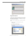
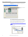
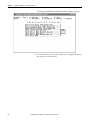
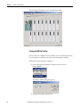
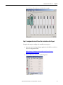
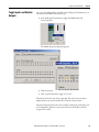
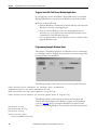
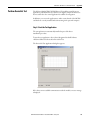
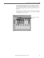
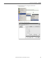
This SoftLogix Chassis Monitor now shows the new controller in slot 1.
Change the RSLinx Software Slot
The RSLinx software module automatically defaults to Slot 0 in the chassis. But
you can program the virtual backplane to use the RSLinx module in another slot
before starting up the SoftLogix application. This flexibility allows a SoftLogix
module to be used in Slot 0 if so desired.
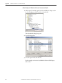
Complete these steps to set up RSLinx software, version 2.59.00 or later, in the
chassis.
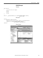
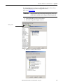
1. In RSLinx software, from the Communications menu, choose
Configure Drivers.
The Configure Drivers dialog box appears.
2. From the Available Driver Types pull-down menu, choose
Virtual Backplane.
Rockwell Automation Publication 1789-UM002K-EN-P - January 2015
29
Chapter 2
What is the SoftLogix System?
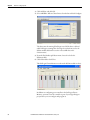
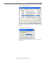
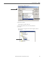
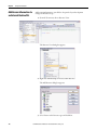
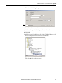
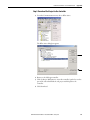
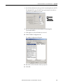
3. Click Add New and click OK.
4. Select AB-VBP-1 RSLinx Classic Driver from the list and click Configure.
The driver must be running if SoftLogix is used. If the driver is deleted
while SoftLogix is running after choosing a slot other than zero for the
RSLinx module, RSLinx chooses the next available slot in the
chassis monitor.
5. From the Slot Number pull-down menu, choose the slot for the
RSLinx module.
6. Click OK and then click Close.
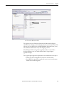
This SoftLogix Chassis Monitor now shows the RSLinx module in slot 5.
In addition to configuring your controller in the SoftLogix Chassis
Monitor, you must create the controller as part of your Logix Designer
project before you can configure and program it.
30
Rockwell Automation Publication 1789-UM002K-EN-P - January 2015
What is the SoftLogix System?
Chapter 2
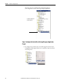
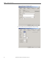
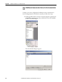
Step 2: Create the New Controller Project in the Logix Designer
Application
1. In the Logix Designer application, from the File menu, choose New.
The New Controller dialog box appears.
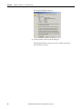
2. In the New Controller dialog box, from the Type pull-down menu, choose
your SoftLogix controller.
3. Enter the controller Name, Chassis Type, and Slot Number to create the
new controller project.
The example above shows the 1789-L60 controller in slot 1.
For Logix Designer application version 20.00.00 or later, slot 0 can
be selected.
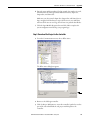
4. Click OK.
Rockwell Automation Publication 1789-UM002K-EN-P - January 2015
31
Chapter 2
What is the SoftLogix System?
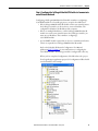
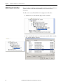
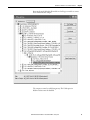
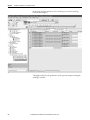
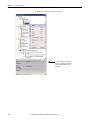
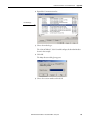
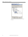
You now see the new controller in the Controller Organizer’s
I/O Configuration section of the Logix Designer application.
Logix Designer Application
Controller Organizer
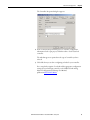
Step 3: Configure the Controller in the Logix Designer Application
Project
1. To configure the controller, in the Controller Organizer, from the I/O
Configuration folder, right-click the new controller you just created and
choose Properties.
32
Rockwell Automation Publication 1789-UM002K-EN-P - January 2015
What is the SoftLogix System?
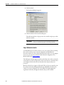
Chapter 2
The Controller Properties dialog box appears.
2. In the Controller Properties dialog box, set controller configuration
information for the open project, and when online—for the attached
controller.
The tabs that appear are particular to the type of controller you have
selected.
3. Click OK when you are done configuring each tab for your controller.
For a complete description of each tab and the appropriate configuration
settings for your SoftLogix controller, see the SERCOS and Analog
Motion Configuration and Startup User Manual,
publication MOTION-UM001.
Rockwell Automation Publication 1789-UM002K-EN-P - January 2015
33
Chapter 2
What is the SoftLogix System?
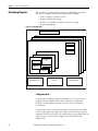
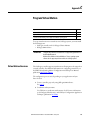
The controller’s execution model is a preemptive, multitasking system that is
IEC 1131-3 compliant. This environment provides the following:
• Tasks to configure controller execution
• Programs to group data and logic
• Routines to encapsulate executable code written in a single
programming language
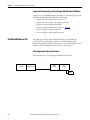
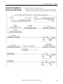
Developing Programs
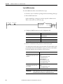
Figure 2 - Control Application
Controller Fault Handler
Task 32
Task 1
Configuration
Status
Watchdog
Program 32
Program 1
Main Routine
Program (local)
Tags
Fault Routine
Other Routines
Controller (global) Tags
I/O Data
System-shared Data
Configuring Tasks
A task provides scheduling and priority information for a set of one or more
programs. You can configure tasks as either continuous or periodic. The
SoftLogix controller supports as many as 32 tasks, only one of which can
be continuous.
A task can have as many as 32 separate programs, each with its own executable
routines and program-scoped tags. Once a task is activated, all of the programs
assigned to the task execute in the order in which they are grouped. Programs can
appear only once in the Controller Organizer and cannot be shared by
multiple tasks.
34
Rockwell Automation Publication 1789-UM002K-EN-P - January 2015
What is the SoftLogix System?
Chapter 2
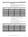
Setting Task Priorities
Each task in the controller has a priority level. The controller uses the priority
level to determine which task to execute when multiple tasks are triggered. There
are 3 configurable priority levels for periodic tasks that range from 1…3, with 1
being the highest priority and 3 being the lowest priority. A higher priority task
will interrupt any lower priority task. The continuous task has the lowest priority
and is always interrupted by any periodic task.
The continuous-task dwell time determines how much time to allow for other
Windows programs, running at a normal priority, to execute. The dwell time is
the time between the end of the continuous task and the start of the next
execution of the continuous task. The dwell time does not affect periodic tasks.
Periodic tasks execute as scheduled, regardless of the dwell time. By default, the
dwell time is 10 ms. This setting has an impact on overall system performance,
see Appendix E.
Tasks Based on Other Events
The SoftLogix controller supports an additional Windows event trigger. This
trigger lets you monitor Windows events in Windows 2000 or Windows XP
operating systems so that applications outside of the SoftLogix controller can
cause a task within the SoftLogix controller to execute. For more information,
see Step 3: Configure the Controller in the Logix Designer Application Project .
Rockwell Automation Publication 1789-UM002K-EN-P - January 2015
35
Chapter 2
What is the SoftLogix System?
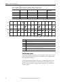
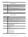
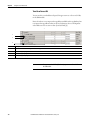
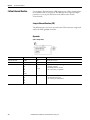
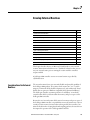
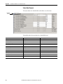
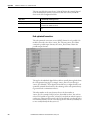
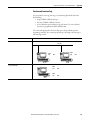
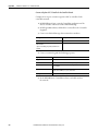
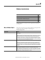
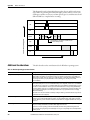
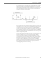
Table 2 - Task Execution Order for Application with Periodic Tasks and Continuous Task
Task
Priority Level
Task Type
Actual Execution Time
Worst Case
Execution Time
1
1
20 ms periodic task
2 ms
2 ms
2
2
10 ms periodic task
4 ms
6 ms
N/A
None (lowest)
Continuous task
25 ms
35 ms
N/A
None
Dwell time
10 ms
14 ms
Task 1
Task 2
Continuous
Task
Dwell
Time
Task
Description
A
The highest priority task interrupts all lower priority tasks.
B
A lower priority task can be interrupted multiple times by a higher priority task.
C
The continuous task runs at the lowest priority and is interrupted by all other tasks.
D
The dwell time starts when the continuous task completes. The dwell time does not affect periodic tasks.
Periodic tasks execute as scheduled, regardless of the dwell time.
E
The continuous tasks restart, when the dwell time completes, unless a higher priority task is running.
Determining Programs
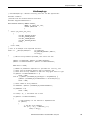
Each program contains program tags, a main executable routine, other routines,
and an optional fault routine. Each task can schedule as many as 100 programs
(including equipment phases).
The scheduled programs within a task execute to completion from first to last.
Programs that are not attached to any task appear as unscheduled programs.
You must specify (schedule) a program within a task before the controller can
scan the program.
36
Rockwell Automation Publication 1789-UM002K-EN-P - January 2015
What is the SoftLogix System?
Chapter 2
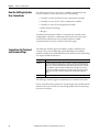
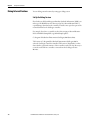
Supporting Routines
A routine is a set of logic instructions in a single programming language, such as
ladder logic. Routines provide the executable code for the project in a controller.
A routine is similar to a program file or subroutine in a PLC or SLC™ processor.
Each program has a main routine. This is the first routine to execute when the
controller triggers the associated task and calls the associated program. Use logic,
such as the JSR instruction, to call other routines.
You can also specify an optional program-fault routine. The controller executes
this routine if it encounters an instruction-execution fault within any of the
routines in the associated program.
The SoftLogix 5800 controller supports routines developed with the relay ladder
and function block editors of the Logix Designer application. You can edit relay
ladder and function block routines either offline or online. You can also develop
C/C++ routines and incorporate them into your project.
See Chapter 5 for information on adding external routines to a project; see
Chapter 6 for information on developing external routines.
Instruction Execution
When performing a math operation, the SoftLogix controller handles INT to
REAL conversions differently than hardware-based Logix controllers. The
SoftLogix controller completes the math operation by using the INT data and
then converts the result to REAL data, which is more consistent with how math
operations occur on personal computers. The hardware-based Logix controllers
first convert INT data to REAL data and then perform the math operation.
The SoftLogix controller also handles the conversion of single-float values to
double-float values differently than the ControlLogix controller. The personal
computer processor calculates conversions to more decimal points than the
ControlLogix controller. This can result in instructions operating differently
between SoftLogix and ControlLogix controllers. For example, when calculating
cam (MAPC) position with the MAPC instruction, the .PC bit can get set
slightly sooner or later in a ControlLogix controller than in a SoftLogix
controller. Factors that affect the time the .PC bit is set are as follows:
• Direction of travel
• Axis scaling constants of the two axes being used for the camming
instruction
• The start and end point values used in the cam
Rockwell Automation Publication 1789-UM002K-EN-P - January 2015
37
Chapter 2
What is the SoftLogix System?
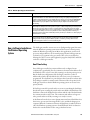
How the SoftLogix System
Uses Connections
The SoftLogix system uses a connection to establish a communication link
between two devices. Connections can be any of the following:
• Controller to local I/O modules or local communication modules
• Controller to remote I/O or remote communication modules
• Controller to remote I/O (rack-optimized) modules
• Produced and consumed tags
• Messages
You indirectly determine the number of connections the controller uses by
configuring the controller to communicate with other devices in the system.
Connections are allocations of resources that provide more reliable
communication between devices than unconnected messages.
Connections for Produced
and Consumed Tags
The SoftLogix controller supports the ability to produce (multicast) and
consume (receive) system-shared tags. System-shared data is accessible by
multiple controllers over an EtherNet/IP network. Produced and consumed tags
each require scheduled connections.
Tag Type
Required Connection
Produced
By default, a produced tag allows two other controllers to consume the tag, which means that as
many as two controllers can simultaneously receive the tag data. The local controller (producing)
must have one connection for the produced tag and the first consumer and one more connection
for each additional consumer (heartbeat). The default produced tag requires two connections.
As you increase the number of controllers that can consume a produced tag, you also reduce the
number of connections the controller has available for other operations, like communication
and I/O.
Consumed
Each consumed tag requires one connection for the controller that is consuming the tag.
The SoftLogix controller supports a maximum of 127 consumed connections.
For two controllers to share produced or consumed tags, both controllers must be
attached to the same network. You cannot bridge produced and consumed tags
between two networks.
38
Rockwell Automation Publication 1789-UM002K-EN-P - January 2015
What is the SoftLogix System?
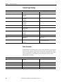
Connections for Messages
Chapter 2
Messages transfer data to other devices, such as other controllers or operator
interfaces. Some messages use unscheduled connections to send or receive data.
These connected messages can leave the connection open (cache) or close the
connection when the message is done transmitting. This table shows which
messages use a connection and whether you can cache the connection.
Message Type
Communication Method
CIP data table read or write
CIP
PLC-2®, PLC-3®, PLC-5®, or SLC (all types)
CIP
Connection
CIP with source ID
CIP generic
DH+™
N/A
Connected messages are unscheduled connections on both ControlNet and
EtherNet/IP networks.
If a message executes repeatedly, cache the connection. This keeps the connection
open and optimizes execution time. Opening a connection each time the message
executes increases execution time.
If a message executes infrequently, do not cache the connection. This closes the
connection upon completion of the message, which frees up that connection for
other uses.
Each message uses one connection, regardless of how many devices are in the
message path. To conserve connections, you can configure one message to read
from or write to multiple devices.
You can cache as many as 16 messages (a combination of any type, not including
block-transfer) at one time. If you try to cache more than 16, the controller
determines the 16 most-currently used messages and caches those. If there are 16
messages cached, and a message is triggered that is currently not cached, the
controller drops the connection of the oldest-cached message to make room for
the new message.
In addition to 16 cached messages, you can also cache as many as 16 blocktransfer messages. The same conditions apply to caching block-transfer messages
as described above for caching other types of messages.
Rockwell Automation Publication 1789-UM002K-EN-P - January 2015
39
Chapter 2
What is the SoftLogix System?
Connections for I/O Modules
The SoftLogix system uses connections to transmit I/O data. These connections
can either be direct connections or rack-optimized connections.
Connection
Description
Direct
A direct connection is a real-time, data transfer link between the controller and an I/O module. The controller maintains and
monitors the connection between the controller and the I/O module. Any break in the connection, such as a module fault or
the removal of a module while under power, causes the controller to set fault status bits in the data area associated with the
module.
Rack-optimized
For digital I/O modules, you can choose rack-optimized communication. A rack-optimized connection consolidates
connection usage between the controller and all of the digital I/O modules on a rack (or DIN rail). Rather than having
individual, direct connections for each I/O module, there is one connection for the entire rack (or DIN rail).
To conserve the number of connections that are available, place digital
I/O modules together in the same location and use a rack-optimized connection.
To choose a rack-optimized connection, choose a ‘rack-optimized’ option for the
communication format when you add the communication device and
I/O modules to the controller project in the Logix Designer application.
If you have analog I/O modules, or want a direct connection to specific
I/O modules, you do not have to create the rack-optimized connection to the
communication device. To use direct connections to I/O modules, choose ‘none’
for the communication format of the communication device.
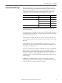
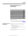
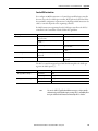
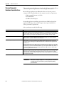
Total Connection
Requirements
The SoftLogix controller supports 250 connections. Each 1784-PCICS
ControlNet communication card supports 128 total connections, 127 of which
can be scheduled. Do not configure more connections than the controller can
support. Use this table to tally ControlNet connections.
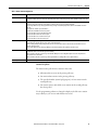
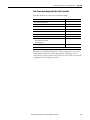
Table 3 - Connections
Connection Type
Device Quantity
Remote EtherNet/IP communication device (such as a 1794-AENT or 1756-ENBT
module):
• Configured as a direct (none) connection
• Configured as a rack-optimized connection
Connections Per
Device
0
1
Remote I/O device over the EtherNet/IP network (direct connection)
1
Produced and consumed tag:
• Produced tag and one consumer
• Each additional consumer
1
Consumed tag
1
Cached message
1
1
Total
40
Rockwell Automation Publication 1789-UM002K-EN-P - January 2015
Total Connections
What is the SoftLogix System?
Restart the Controller
Chapter 2
You restart the controller by either of these methods:
• Restarting the computer
• Removing and reinserting the controller in the virtual chassis
After restarting the controller, you must upload or download from the Logix
Designer application before you can go online with the controller. This is because
the project file (.ACD) contains explicit knowledge of the physical memory
addresses used by the controller. When you restart the controller, all of the
physical addresses for the controller are regenerated. Note that as long as the
controller is not restarted, you can go online and offline as many times as
required.
Online with the Controller
You must save the Logix Designer application project after a download
completes, or you will not be able to go online with the controller. After
downloading, the physical address information has changed. The Logix Designer
application prompts you to save and indicates that a change has occurred even
though you might not have made changes to the project. Saving the project stores
the physical address information into the ACD file.
An upload recovers all of the information that was downloaded to the controller,
including documentation. This is because of the persistent storage feature that
you enable by specifying a periodic save interval (see page 26). On a download,
the persistent storage copies the entire project file to the controller. The
controller opens and goes online with the project file so that any edits made by
Logix Designer application workstations are saved into the persistent image (the
controller's copy of the project file). Online edits are saved to the persistent image
immediately; tag data values are saved to the persistent image at every periodic
save interval (10 min default). If the periodic save is disabled, tag data values are
not saved, but online edits are still saved to the persistent image.
The SoftLogix controller maintains a change log that holds 999 entries. This
means that as you edit a Logix Designer project file, you must save the project file
before you make 999 changes. If you make more than 999 changes to a project,
you will not be able to go back online without performing an upload or
a download.
Upload to the Controller
If your project has edits and you want to upload the project to the controller, the
Logix Designer application prompts you to save the project before uploading.
Regardless of your choice, the edits are saved before the upload occurs. This
happens because the edits are already stored in the controller as you make
the edits.
Rockwell Automation Publication 1789-UM002K-EN-P - January 2015
41
Chapter 2
What is the SoftLogix System?
Select a System Overhead
Percentage
The Controller Properties dialog box lets you specify a percentage of controller
time (excluding the time for periodic tasks) that is devoted to communication
and background functions.
1. In the Logix Designer application, from the Controller Organizer, rightclick the controller and choose Properties.
2. Click the Advanced tab.
3. In the System Overhead Time Slice box, enter a percentage.
The system overhead function interrupts the continuous task. The percentage
you specify determines the amount of the continuous task to allocate to system
overhead functions, which include the following:
• Communicating with programming and HMI devices (such as
RSLogix 5000 software)
• Responding to messages
• Sending messages, including block-transfers
• Re-establishing and monitoring I/O connections (such as RIUP
conditions); this does not include normal I/O communication that occurs
during program execution
• Bridging communication from one communication device to another
communication device across the virtual chassis
This function allows the controller to take care of communication requests that
occur from other controllers or from queued requests from within the controller’s
application program. If communication is not completing fast enough, increase
the system overhead percentage.
Because the SoftLogix controller runs natively on your computer's Pentium CPU,
the default setting of 10% yields satisfactory performance for most applications.
42
Rockwell Automation Publication 1789-UM002K-EN-P - January 2015
Chapter
3
Communicate with Devices on an
Ethernet Network
Topic
Page
Configure Your System for an Ethernet Network
43
Multiple EtherNet/IP Modules
54
Controller Connections over the EtherNet/IP Network
55
Distributed Ethernet I/O
56
Add a Remote Controller
60
Check EtherNet/IP Statistics
63
Example 1: Workstation Remotely Connected to a SoftLogix Controller
65
Example 2: Send Messages over the EtherNet/IP Network
68
Example 3: Send Messages over the EtherNet/IP Network to a PLC-5 Processor
71
Example 4: Control Distributed I/O
73
This chapter explains how to communicate with a device on an Ethernet network
by using the SoftLogix controller.
For information about communicating with EtherNet/IP devices, see the
EtherNet/IP Network Configuration User Manual, publication ENET-UM001.
Configure Your System for an
Ethernet Network
For the SoftLogix controller to operate on an EtherNet/IP network, you need
the following:
• A computer where the SoftLogix controller resides enabled with an
Ethernet communication port
• The Logix Designer application installed
• A computer where the Logix Designer application resides enabled with an
Ethernet communication port
• RSLinx software installed
You can use any commercially-available Ethernet port. Use the Ethernet driver
that comes with the device.
Rockwell Automation Publication 1789-UM002K-EN-P - January 2015
43
Chapter 3
Communicate with Devices on an Ethernet Network
Step 1: Disable UDP Messages in RSLinx Classic Software
To send messages, or control I/O, you must change the RSLinx Classic
configuration so that it does not accept UDP messages.(1)
1. Launch RSLinx software on the computer with the controller.
2. From the View menu, choose Options.
The Options dialog box appears.
3. On the General tab, clear ‘Accept UDP Messages on the Ethernet Port’.
4. Click OK.
5. Restart your computer.
(1) RSLinx Enterprise software may have other requirements. For details, see the MySupport Knowledgebase
at http://www.rockwellautomation.com/support.
44
Rockwell Automation Publication 1789-UM002K-EN-P - January 2015
Communicate with Devices on an Ethernet Network
Chapter 3
Disabling the UDP option
Disabling the UDP option lets RSLinx software and the SoftLogix 5800
EtherNet/IP functionality coexist on the same personal computer. Disabling the
UDP option also disables RSLinx software’s Gateway functionality. RSLinx
software still functions, but the Gateway options are removed while RSLinx
software continues to display that it has a full Gateway activation. This affects
how remote computers can browse through a local computer with UDP disabled.
If UDP is disabled on a local computer, a remote computer browsing through the
local computer has this functionality:
• If the local computer has a DeviceNet module in the virtual chassis, you
cannot remotely browse the DeviceNet network. Replacing RSLinx Lite
with RSLinx Gateway software on the local or remote computer does not
enable remote browsing of the DeviceNet network.
• If the local computer has a ControlNet module in the virtual chassis, you
can remotely browse the ControlNet network.
• If the local computer has a SoftLogix controller in the virtual chassis, you
can browse the serial port of the computer.
• If the local computer has an EtherNet/IP module in the virtual chassis, you
can browse the EtherNet/IP network configured to that module.
• The local computer supports a remote connection to the SoftLogix
controller over an Ethernet network so that you can remotely program the
SoftLogix controller.
Rockwell Automation Publication 1789-UM002K-EN-P - January 2015
45
Chapter 3
Communicate with Devices on an Ethernet Network
If UDP is disabled on a local computer, you can browse the ControlNet and
EtherNet/IP networks and serial devices to see configured devices, as long as the
appropriate module is installed in the virtual chassis on the local computer.
To be able to browse DeviceNet networks, RSLinx Gateway functionality (and
therefore UDP) must be enabled on the computer that hosts the DeviceNet
communication card.
Enabling the UDP option
Enabling the UDP option lets the RSLinx Gateway functionality operate as
expected. Installing a SoftLogix 5800 EtherNet/IP module into a system with the
UDP option enabled and RSLinx Gateway functionality enabled, causes the
SoftLogix EtherNet/IP module to display a red X in the chassis monitor. This
does not affect the operation of the RSLinx software. It does prohibit the
SoftLogix controller from sending and receiving messages and controlling
I/O modules via an EtherNet/IP network.
Adding multiple Ethernet modules does not affect controller operation when
UDP is enabled. Checking the Enable UDP box applies to all Ethernet ports on
the computer; RSLinx Gateway software will use all of the Ethernet ports.
Enable the UDP option and the RSLinx Gateway functionality when you need
the computer to configure or commission ControlNet and DeviceNet networks
and devices. With the UDP option enabled, you have this functionality and loss
of functionality in the computer where the controller resides:
• You must browse from the 1784-PCIDS driver in RSLinx software to
browse a DeviceNet network.
• You can remotely browse the ControlNet network if there is a
ControlNet module in the virtual chassis.
• You can browse over the serial port of the computer if there is a
SoftLogix controller in the virtual chassis.
• You can remotely program the SoftLogix controller because the local
computer supports a remote connection to the SoftLogix controller over
an Ethernet network.
• If there is an EtherNet/IP module in the virtual chassis, it will not function
as expected. You cannot control I/O or send messages.
• You can remotely program the SoftLogix controller because the local
computer supports a remote connection to the SoftLogix controller over
an Ethernet network.
46
Rockwell Automation Publication 1789-UM002K-EN-P - January 2015
Communicate with Devices on an Ethernet Network
Chapter 3
If you want the UDP option enabled, you should also enable the Gateway
functionality within RSLinx Gateway software. You must have RSLinx Gateway
software to enable Gateway functionality. Follow these steps.
1. Launch RSLinx software on the computer with the controller.
2. From the Communications menu, choose Configure Gateway.
The Configure RSLinx Gateway dialog box appears.
3. Check Enable RSLinx Gateway.
4. Click OK.
In many applications, initially leave UDP enabled so that you can configure
ControlNet and DeviceNet networks. After configuration is done, disable UDP
so the SoftLogix controller can have EtherNet/IP functionality. If you change the
UDP setting, you must restart RSLinx software for the change to take affect. To
restart RSLinx software, restart the computer.
For information on adding multiple Ethernet modules, see page 54.
Rockwell Automation Publication 1789-UM002K-EN-P - January 2015
47
Chapter 3
Communicate with Devices on an Ethernet Network
Step 2: Create the Communication Card in the SoftLogix Chassis
Monitor
Add the EtherNet/IP module to the SoftLogix virtual chassis if you are
controlling I/O or sending messages over Ethernet network. These instructions
show a a SoftLogix controller installed already in slot 4. Follow these steps to add
an EtherNet/IP module to your chassis.
1. In the SoftLogix Chassis Monitor, from the Slot menu, choose Create
Module.
Or right-click the appropriate slot and choose Create.
The Select Module dialog box appears.
2. In the Select Module dialog box, select the EtherNet/IP SoftLogix 5800
EtherNet/IP communication module.
3. Enter the backplane slot number.
For the Logix Designer application, version 20.00.00 or later, you can
specify any slot number for the communication card, as long as the RSLinx
software module is positioned in a slot other than its default 0.
See page 29.
4. Click OK.
48
Rockwell Automation Publication 1789-UM002K-EN-P - January 2015
Communicate with Devices on an Ethernet Network
Chapter 3
The Select Device dialog box appears.
10.88.94.12
255.255.252.0
10.88.92.1
00:13:20:03:C1:1E
5. Select the serial number of the port you want.
If you previously had an Ethernet port configured in this slot, the chassis
monitor remembers the configuration of that previous port.
6. Click Next.
The Module Properties General dialog box appears.
7. Specify a label name for the EtherNet/IP I/O Module Marquee.
The IP address, status, and the label name you enter here scrolls across the
front of the module.
8. Click Finish.
Rockwell Automation Publication 1789-UM002K-EN-P - January 2015
49
Chapter 3
Communicate with Devices on an Ethernet Network
This chassis monitor shows the selected IP address as a virtual module in the
SoftLogix chassis.
This chassis monitor has an EtherNet/IP module
installed in slot 3.
Step 3: Configure the Communication Card as Part of the Project
If you want to control I/O over an EtherNet/IP network, use the Logix Designer
application to add the SoftLogix 5800 EtherNet/IP module to your project.
You should already have added the SoftLogix controller to the project.
See Step 2: Create the New Controller Project in the Logix Designer Application
on page 31,
Your controller is offline.
1. In the Logix Designer project, right-click the Ethernet module in the I/O
Configuration folder, and choose New Module.
50
Rockwell Automation Publication 1789-UM002K-EN-P - January 2015
Communicate with Devices on an Ethernet Network
Chapter 3
The Select Module dialog box appears.
2. Expand the Communications list and choose the 1756-EWEB/A module.
3. Click OK.
The Select Major Revision dialog box appears.
4. From the Major Revision pull-down menu, choose the revision number
and click OK.
Rockwell Automation Publication 1789-UM002K-EN-P - January 2015
51
Chapter 3
Communicate with Devices on an Ethernet Network
The Module Properties dialog box appears.
5. Name the module, enter the IP address, and select the
Disable Keying option.
6. Click OK.
The Module Properties dialog box appears.
52
Rockwell Automation Publication 1789-UM002K-EN-P - January 2015
Communicate with Devices on an Ethernet Network
Chapter 3
Step 4: Configure the SoftLogix EtherNet/IP Module to Communicate
on an Ethernet Network
Configuring a SoftLogix 5800 EtherNet/IP module is similar to configuring a
1756-ENBT module in a ControlLogix project, except for these differences:
• If the SoftLogix 5800 EtherNet/IP module is in the same virtual chassis as
the SoftLogix controller, you do not have to enter an IP address. The
configuration defaults to the IP address of the computer.
• If there are multiple IP addresses, or if the SoftLogix 5800 EtherNet/IP
module is not in the same virtual chassis as the SoftLogix controller, you
must enter an IP address. This is similar to configuring a
1756-ENBT module.
• A 1756-ENBT module requires that you choose a communication format.
This is not required for a SoftLogix 5800 EtherNet/IP module.
Refer to the EtherNet/IP Network Configuration User Manual,
publication ENET-UM001, for more information on configuring the
1756-ENBT module. The SoftLogix module is configured the same way.
When you have completed configuration, click OK and save the project.
Your Logix Designer application project’s I/O configuration folder should
now look similar to this example.
Rockwell Automation Publication 1789-UM002K-EN-P - January 2015
53
Chapter 3
Communicate with Devices on an Ethernet Network
Multiple EtherNet/IP
Modules
If the computer has multiple IP addresses available, you can install multiple
Ethernet modules in the virtual chassis. Choose the appropriate IP address when
you configure the EtherNet/IP module in the virtual chassis.
The configuration you choose for the UDP option in RSLinx software applies to
every IP address on the same computer. RSLinx software does not support
separate UDP configurations per IP address or actual Ethernet device. If you
enable UDP functionality in RSLinx software, RSLinx software consumes all IP
addresses on the computer.
Ethernet Communication
With multiple Ethernet modules, the SoftLogix 5800 controller can receive an
I/O connection error due to conflicting naming conventions with Windows
operating systems. To avoid this, place all of the following:
• Produced and consumed tags and I/O devices on one Ethernet module.
• MSG instructions on a different Ethernet module.
To connect to the Ethernet network, launch RSLinx software.
Domain Interactions
In a system with multiple Ethernet modules, you can connect to different
networks. For example, this multi-homing system has two Ethernet modules.
SoftLogix Ethernet Module 1
SoftLogix Ethernet Module 2
Item
Description
1
Ethernet module 1 connected to the corporate network
• Member server in the domain
• Searches for name and DNS information
• Dynamic configuration
2
Ethernet module 2 connected to the plant network
• No existing domain control
• DNS not available
• Static configuration
In this example, because Ethernet module 1 is dynamically configured, Ethernet
module 2 is unable to get routing information to a gateway and cannot
successfully send or receive multicast packets.
54
Rockwell Automation Publication 1789-UM002K-EN-P - January 2015
Communicate with Devices on an Ethernet Network
Chapter 3
Possible solutions include the following.
Solution
Description
Multi-homed Windows 2003 member server on active
directory or mixed domain
Connect both Ethernet modules to domain controllers so that they both receive correct routing information.
Multi-homed personal computer not connected to a
domain and set up in a work group.
Configure both Ethernet modules with correct IP address information by using either a DHCP server or by static IP
address assignment. When IP address information is assigned to the Ethernet modules, the modules do not have to
independently determine domain relationships.
IMPORTANT
Controller Connections over
the EtherNet/IP Network
If you have multiple networks, you must have gateways configured to reach
those networks.
A Logix system uses a connection to establish a communication link between two
devices. Connections can be the following:
• Controller to distributed I/O or remote communication modules
• Produced and consumed tags
• Messages
All EtherNet/IP connections are unscheduled. An unscheduled connection is a
message transfer between controllers that is triggered by the requested packet
interval (RPI) or the program (such as an MSG instruction). Unscheduled
messaging lets you send and receive data when needed.
Over EtherNet/IP network, the SoftLogix controller supports the following:
• 64 TCP/IP connections for EtherNet/IP communication
• 1 single TCP connection can support multiple CIP connections
• 128 CIP connections for Logix-based communication
A CIP connection transfers data from one Logix application running on
one end-node to a second Logix application running on another end-node.
A CIP connection is established over a TCP connection.
Rockwell Automation Publication 1789-UM002K-EN-P - January 2015
55
Chapter 3
Communicate with Devices on an Ethernet Network
Supported Functionality of the SoftLogix 5800 EtherNet/IP Module
Compared to a 1756-ENBT EtherNet/IP module in a ControlLogix system, the
SoftLogix 5800 EtherNet/IP module does the following:
• Supports the same number of I/O connections
• Supports the same number of messaging connections
• Supports the same bridging functionality
• Supports an EtherNet/IP statistics utility (see page 63)
• Does not support a web-based interface
• Does not support email via MSG instruction
Distributed Ethernet I/O
The SoftLogix controller supports distributed I/O over an EtherNet/IP
network. Use the Logix Designer application to add the SoftLogix 5800
EtherNet/IP module for the local controller; then add a remote adapter and I/O
modules to the I/O Configuration folder of the controller project.
I/O Configuration Order in the Project
This example shows a typical SoftLogix distributed I/O network.
Controller
Ethernet
Communication Port
Remote
Adapter
I/O
Module
Device
56
Rockwell Automation Publication 1789-UM002K-EN-P - January 2015
Communicate with Devices on an Ethernet Network
Chapter 3
You build the I/O configuration in this order.
1. Add (see page 50) the remote adapter to the SoftLogix 5800
EtherNet/IP module of the controller (1794-AENT/A
remote_flex_adapter).
Module
Adapter
2. Add (see page 50) the I/O modules to the remote adapter (1794-IA16/A
remote_flex_input, 1794-CB16/A remote_flex_output, 1794IF2XOF2I/A remote_flex_combo).
Adapter
Distributed I/O
Modules
Rockwell Automation Publication 1789-UM002K-EN-P - January 2015
57
Chapter 3
Communicate with Devices on an Ethernet Network
Ethernet I/O Data
I/O information is presented as a structure of multiple fields, which depend on
the specific features of the I/O module. The name of the structure is based on the
location of the I/O module in the system. Each I/O tag is automatically created
when you configure the I/O module through the programming software. Each
tag name follows this format:
Location:SlotNumber:Type.MemberName.SubMemberName.Bit
58
This address variable
Is
Location
Identifies network location
ADAPTER_NAME = identifies remote adapter or bridge
SlotNumber
Slot number of I/O module in its chassis
Type
Type of data
I = input
O = output
C = configuration
S = status
MemberName
Specific data from the I/O module; depends on the type of data the module can store.
For example, Data and Fault are possible fields of data for an I/O module. Data is the common name for values the are sent to or received
from I/O points.
SubMemberName
Specific data related to a MemberName.
Bit (optional)
Specific point on the I/O module; depends on the size of the I/O module (0…31 for a 32-point module)
Rockwell Automation Publication 1789-UM002K-EN-P - January 2015
Communicate with Devices on an Ethernet Network
Chapter 3
See this example.
EXAMPLE
Device
Example Tag Names (automatically created by the software)
remote adapter ‘remote_flex_adapter’
remote_flex_adapter:I
remote_flex_adapter:I.SlotStatusBits
remote_flex_adapter:I.Data
remote_flex_adapter:O
remote_flex_adapter:O.Data
‘remote_flex_input’ in slot 0
rack-optimized connection
remote_flex_adapter:0:C
remote_flex_adapter:0:C.Config
remote_flex_adapter:0:C.DelayTime_0
remote_flex_adapter:0:C.DelayTime_1
remote_flex_adapter:0:C.DelayTime_2
remote_flex_adapter:0:C.DelayTime_3
remote_flex_adapter:0:C.DelayTime_4
remote_flex_adapter:0:C.DelayTime_5
remote_flex_adapter:0:I
‘remote_flex_output’ in slot 1
rack-optimized connection
remote_flex_adapter:1:C
remote_flex_adapter:1:C.SSData
remote_flex_adapter:1:O
remote_flex_adapter:1:O.Data
‘remote_flex_combo’ in slot 2
direct connection
remote_flex_adapter:2:C
remote_flex_adapter:2:C.InputFIlter
remote_flex_adapter:2:C.InputConfiguration
remote_flex_adapter:2:C.OutputConfiguration
remote_flex_adapter:2:C.RTSInterval
remote_flex_adapter:2:C.SSCh0OuputData
remote_flex_adapter:2:C.SSCH1OutputData
remote_flex_adapter:2:I
Rockwell Automation Publication 1789-UM002K-EN-P - January 2015
59
Chapter 3
Communicate with Devices on an Ethernet Network
Add a Remote Controller
If you want this controller to consume tags from another controller via Ethernet,
add the controller to the EtherNet/IP module. The consumer initiates
any actions.
To add a remote controller, build the I/O configuration in this order.
1. Add the devices to the EtherNet/IP port of the controller.
2. For a controller that requires a communication module, add the module
first, and then add the controller.
60
Rockwell Automation Publication 1789-UM002K-EN-P - January 2015
Communicate with Devices on an Ethernet Network
Chapter 3
Add a Consumed Tag
A consumed tag’s value comes from a remote controller. The local controller is
the consumer, and the remote controller is the producer. Consumed tags are
always at controller scope.
Complete these steps to add a consumed tag.
1. On the Controller folder in the Controller Organizer, right-click
Controller Tags and choose New tag.
The New Tag dialog box appears.
Rockwell Automation Publication 1789-UM002K-EN-P - January 2015
61
Chapter 3
Communicate with Devices on an Ethernet Network
2. Enter tag configuration information.
Parameter
Description
Name
Enter the name of the tag.
Description
Enter a tag description.
Type
Consumed.
Data Type
Enter the type of tag you want to create.
Scope
Consumed tags are always controller scope.
External Access
Select whether the tag has Read/Write, Read Only, or no access (None) from external applications such as HMIs.
Style
Choose the default style in which to display the value of the tag. The pull-down menu lists available display styles for the
chosen data type. Choose from Binary, Decimal, Hex, Octal, Date/Time, ASCII, Exponential, or Float.
3. Click Connection.
The Consumed Tag Connection dialog box appears.
4. Configure connection properties in the Consumed Tag Connection
dialog box.
Parameter
Description
Producer
Choose the name of the controller producing the data. The pull-down menu lists only those options that are available.
Remote Data
Enter the name of the tag in the remote controller that you want to consume.
RPI
Enter the requested packet interval. This is the amount of time (in ms) between updates of the data from the remote
controller. This is the minimum rate at which the local controller receives data. The valid RPI range for a Standard
consumed tag is 0.196…536870.911 ms. The valid RPI range for a Safety consumed tag is 1…500 ms and can only be
set on the Safety tab of the Consumed Tag Connection dialog box. Note that the Safety Tag RPI must match the rate
specified by Safety Task Period of the producing controller.
You must be offline or online in Program mode to change the RPI.
5. Click OK when done.
62
Rockwell Automation Publication 1789-UM002K-EN-P - January 2015
Communicate with Devices on an Ethernet Network
Chapter 3
To view the tag, from the Controller, double click the Controller Tags folder in
the Controller Organizer.
Check EtherNet/IP Statistics
The SoftLogix controller installs with an EtherNet/IP statistics utility that
displays different counters for the EtherNet/IP module.
Complete these steps to display the statistics.
1. Choose the EtherNet/IP Statistics Utility from the folder where you
installed the SoftLogix controller.
Rockwell Automation Publication 1789-UM002K-EN-P - January 2015
63
Chapter 3
Communicate with Devices on an Ethernet Network
The SoftLogix 5800 EtherNet/IP Module Statistics dialog box appears.
2. Use the character key at the top of the utility screen to display information
and change screen characteristics.
64
Rockwell Automation Publication 1789-UM002K-EN-P - January 2015
Communicate with Devices on an Ethernet Network
Example 1: Workstation
Remotely Connected to a
SoftLogix Controller
Chapter 3
In this example, a workstation remotely connects to a SoftLogix controller over
an Ethernet network to remotely program the SoftLogix controller.
2
3
4
5
1
7
8
6
9
10
11
12
Item
Description
1
Ethernet switch
2
Firewall/router
3
ControlLogix chassis with controller and Ethernet module
4
PanelView terminal
5
Personal computer running RSLinx software and the Logix Designer application
6
Ethernet switch
7
FLEX I/O system with Ethernet adapter
8
ControlLogix gateway
9
To ControlNet network
10
To DeviceNet network
11
To DH+ network
12
SoftLogix 5800 controller
Rockwell Automation Publication 1789-UM002K-EN-P - January 2015
65
Chapter 3
Communicate with Devices on an Ethernet Network
Browsing from a computer to a remote SoftLogix controller looks like
this example.
66
Rockwell Automation Publication 1789-UM002K-EN-P - January 2015
Communicate with Devices on an Ethernet Network
Chapter 3
Browsing from the EtherNet/IP module in a SoftLogix controller to remote
devices looks like this example.
The computer cannot be an RSLinx gateway. The UDP option in
RSLinx software must be disabled.
Rockwell Automation Publication 1789-UM002K-EN-P - January 2015
67
Chapter 3
Communicate with Devices on an Ethernet Network
Example 2: Send Messages
over the EtherNet/IP
Network
In the following example, the SoftLogix controller can send messages to the other
devices on the EtherNet/IP network.
2
3
5
4
1
7
8
6
9
10
11
12
68
Item
Description
1
Ethernet switch
2
Firewall/router
3
ControlLogix chassis with controller and Ethernet module
4
PanelView terminal
5
Personal computer running RSLinx software and the Logix Designer application
6
Ethernet switch
7
FLEX I/O system with Ethernet adapter
8
ControlLogix gateway
9
To ControlNet network
10
To DeviceNet network
11
To DH+ network
12
SoftLogix 5800 controller
Rockwell Automation Publication 1789-UM002K-EN-P - January 2015
Communicate with Devices on an Ethernet Network
Chapter 3
Configure a MSG Instruction
How you configure the MSG instruction depends on the target device.
1. Click MSG to launch the Message Configuration dialog box.
2. On the Configuration tab, configure the following.
For this item
Specify
Message Type
CIP Data Table Read or
CIP Data Table Write
Source Element
Tag containing the data to be transferred
Number of Elements
Number of array elements to transfer
Destination Tag
Tag to which the data will be transferred
Rockwell Automation Publication 1789-UM002K-EN-P - January 2015
69
Chapter 3
Communicate with Devices on an Ethernet Network
On the Communication tab, specify the communication path.
A communication path requires pairs of numbers. The first number in the
pair identifies the port from which the message exits. The second number
in the pair designates the node address of the next device.
70
For this item
Specify
Communication Path
(Each SoftLogix controller resides in its
own computer)
1,2,130.151.255.43,1,5
where:
1 is the SoftLogix backplane of Soft1
2 is Ethernet port in slot 5
130.151.255.43 is IP address of the target
1 is the SoftLogix backplane of Soft2
5 is the controller slot of Soft2
Communication Path
(Each SoftLogix controller resides in the
same computer)
1,5
where:
1 is the SoftLogix backplane of Soft1
5 is the controller slot of Soft2
Rockwell Automation Publication 1789-UM002K-EN-P - January 2015
Communicate with Devices on an Ethernet Network
Example 3: Send Messages
over the EtherNet/IP
Network to a PLC-5 Processor
Chapter 3
In this example, the SoftLogix controller sends a message through the
1756-ENBT, out the 1756-DHRIO, and to a PLC-5 processor at DH+ node 2.
1
3
2
4
5
Item
Description
1
SoftLogix 5800 controller
2
Ethernet network
3
ControlLogix controller with 1756-ENBT and 1756-DHRIO modules
4
DH+ network
5
PLC-5 processor
Configure a MSG Instruction
Use a PLC-5 Typed Write MSG instruction.
Rockwell Automation Publication 1789-UM002K-EN-P - January 2015
71
Chapter 3
Communicate with Devices on an Ethernet Network
Specify the path and communication method.
The example path is 1, 6, 2, 10.88.55.186, 1, 2.
This value
Specifies
1
The SoftLogix virtual chassis
6
The sending device (the Ethernet port in the controller’s computer) is in slot 6 of
the virtual chassis
2
Sending the message out the Ethernet communication port
10.88.55.186
The IP address of the 1756-ENBT module
1
The 1756 backplane
2
The slot where the 1756-DHRIO module is in the 1756 chassis
This is an example communication method.
72
This field
Specifies
Channel = A
Channel A on the 1756-DHRIO module
Source Link = 3
The DH+ address of the 1756-DHRIO module is node 3
Destination Node = 2
The DH+ address of the PLC-5 processor is node 2
Rockwell Automation Publication 1789-UM002K-EN-P - January 2015
Communicate with Devices on an Ethernet Network
Example 4: Control
Distributed I/O
Chapter 3
In this example, one SoftLogix controller controls distributed I/O through a
1794-AENTmodule.
2
1
3
Item
Description
1
EtherNet/IP network
2
SoftLogix controller (Soft1)
3
1794-AENT with distributed I/O (remote_flex_adapter)
This example has Soft1 controlling the I/O connected to the remote
1794-AENT module. The data the SoftLogix controller receives from the
distributed I/O modules depends on how you configure the I/O modules. You
can configure each module as a direct connection or as rack optimized. One
chassis can have a combination of some modules configured as a direct
connection and others as rack optimized.
All analog modules require direct connections. Diagnostic modules support
rack-optimized connections, but require direct connections to take full advantage
of the diagnostic feature.
Rockwell Automation Publication 1789-UM002K-EN-P - January 2015
73
Chapter 3
Communicate with Devices on an Ethernet Network
In the Logix Designer application, the controller project and associated tags
looks like this example.
Throughput is based on the performance of the personal computer running the
SoftLogix controller.
74
Rockwell Automation Publication 1789-UM002K-EN-P - January 2015
Chapter
4
Communicate with Serial Devices
Topic
Page
Configure Your System for a Serial Device
75
Controller Status Indicators
85
Example 1: Workstation Directly Connected to a SoftLogix Controller
85
Example 2: Workstation Remotely Connected to a SoftLogix Controller
86
Example 3: SoftLogix Controller to a Bar Code Reader
90
This chapter explains how to use a serial device with your SoftLogix system.
Details on configuring your system for a serial device and examples are included.
IMPORTANT
Configure Your System for a
Serial Device
Limit the length of serial (RS-232) cables to 15.2 m (50 ft).
For the SoftLogix controller to operate with a serial device, you need
the following:
• A computer where the SoftLogix controller resides to have a serial port
• RSLinx software to configure the serial communication driver
If a remote computer communicates with the SoftLogix controller via a
serial connection, the remote computer must have the serial driver
installed. The computer with the SoftLogix controller does not need the
serial driver to connect to other devices over a serial device
• Logix Designer application to configure the serial port of the controller
Rockwell Automation Publication 1789-UM002K-EN-P - January 2015
75
Chapter 4
Communicate with Serial Devices
Step 1: Configure the Serial Port
Use the SoftLogix Chassis Monitor to choose which COM port to use for serial
communication. The controller supports only one COM port for DF1
communication.
Follow these steps to configure serial communication.
1. In the SoftLogix Chassis Monitor, from the Slot menu, choose
Create Module.
Or right-click the appropriate slot and choose Create.
The Select Module dialog box appears.
2. In the Select Module dialog box, choose the 1789-L60 SoftLogix5860
Controller.
3. Choose the backplane slot number.
For this example, we will choose Slot 1.
4. Click OK.
76
Rockwell Automation Publication 1789-UM002K-EN-P - January 2015
Communicate with Serial Devices
Chapter 4
The General dialog box appears.
5. Specify the settings for the controller.
6. Click Next.
The NT System dialog box appears.
7. Choose the COM port.
8. Click Finish.
Rockwell Automation Publication 1789-UM002K-EN-P - January 2015
77
Chapter 4
Communicate with Serial Devices
Your SoftLogix Chassis Monitor now looks like this example.
Change the COM Port Setting
Once you choose a COM port for the controller, you can only change the setting
by removing the controller from the chassis and reinstalling the controller.
Follow these steps to change the COM port.
1. In the SoftLogix Chassis Monitor, from the Slot menu, choose
Remove Module.
The Remove Module dialog box appears.
2. Verify the slot number and click OK.
78
Rockwell Automation Publication 1789-UM002K-EN-P - January 2015
Communicate with Serial Devices
Chapter 4
The Remove Module verification dialog box appears.
Do not clear the SoftLogix Chassis Monitor module
configuration unless you want to enter all new information.
3. Click OK.
The SoftLogix Chassis Monitor now appears with slot 1 empty.
Rockwell Automation Publication 1789-UM002K-EN-P - January 2015
79
Chapter 4
Communicate with Serial Devices
4. In the same slot, re-add the controller.
COM port.
The SoftLogix Chassis Monitor prompts whether to use the
previous configuration.
5. Click Next.
80
Rockwell Automation Publication 1789-UM002K-EN-P - January 2015
Communicate with Serial Devices
Chapter 4
Your SoftLogix Chassis Monitor looks like this example.
Step 2: Configure the Serial Port of the Controller in the Project
Complete these steps to configure the controller in your project.
1. Open a project in the Logix Designer application and add the controller to
the I/O Configuration folder.
Refer to Step 3: Configure the Controller in the Logix Designer
Application Project on page 32.
2. From the Edit menu, choose Controller Properties.
Rockwell Automation Publication 1789-UM002K-EN-P - January 2015
81
Chapter 4
Communicate with Serial Devices
The Controller Properties dialog box appears.
3. On the Serial Port tab, specify the appropriate serial port settings.
82
Rockwell Automation Publication 1789-UM002K-EN-P - January 2015
Communicate with Serial Devices
Chapter 4
Specify Serial Port Characteristics
Specify these characteristics on the Serial Port tab.
Characteristic
Description
Mode
Choose System (for DF1 communication) or User mode (for ASCII communication).
Baud Rate
Specifies the communication rate for the serial port. Choose a baud rate that all devices in your system support.
Select 110, 300 600, 1200, 2400, 4800, 9600, or 19200 KBps.
Data Bits
Specifies the number of bits per message packet.
Choose 8. (7 is ASCII only.))
Parity
Specifies the parity setting for the serial port. Parity provides additional message-packet error detection. Parity is an additional non-data bit attached
to a binary word. Its purpose is to provide a check of the data integrity by making the sum of the number of ones in a word always even or odd.
Choose None or Even.
Stop bits
Specifies the number of stop bits to the device with which the controller is communicating.
Choose 1. (2 is ASCII only.)
Control line
Specifies the mode in which the serial driver operates.
Choose No Handshake, Full-Duplex, Half-Duplex with Continuous Carrier, or Half-Duplex without Continuous Carrier.
If you are not using a modem, choose No Handshake
If both modems in a point-to-point link are full-duplex, choose Full-Duplex for both controllers.
If the master modem is full duplex and the slave modem is half-duplex, choose Full-Duplex for the master controller and choose Half-Duplex with
Continuous Carrier for the slave controller.
If all the modems in the system are half-duplex, choose Half-Duplex without Continuous Carrier for the controller.
RTS Send Delay
Enter a count that represents the number of 20 ms periods of time that elapse between the assertion of the RTS signal and the beginning of a
message transmission. This time delay lets the modem prepare to transmit a message. The CTS signal must be high for the transmission to occur.
The range is 0…32767 periods.
RTS Off Delay
Enter a count that represents the number of 20 ms periods of time that elapse between the end of a message transmission and the de-assertion of
the RTS signal. This time delay is a buffer to make sure the modem successfully transmits the entire message.
The range is 0…32767 periods. Normally leave at zero.
DCD Wait Delay
Applies to the DF1 Radio Modem protocol only.
Rockwell Automation Publication 1789-UM002K-EN-P - January 2015
83
Chapter 4
Communicate with Serial Devices
4. Click the System Protocol tab and specify the appropriate settings.
Specify System Protocol Characteristics
These are the available system modes and their characteristics.
Table 4 - System Protocol Tab Descriptions
Field
Mode
Protocol
DF1 Master - control of polling and message transmission between the master and slave nodes.The master/slave network includes one
controller configured as the master node and as many as 254 slave nodes. Link slave nodes by using modems or line drivers.
A master/slave network can have node numbers from 0…254. Each node must have a unique node address. Also, at least 2 nodes must exist
to define your link as a network (1 master and 1 slave station are the two nodes).
See page 88.
DF1 Point-to-Point - communication between the controller and one other DF1-protocol-compatible device. This is the default system
mode.This mode is typically used to program the controller through its serial port.
See page 86.
DF1 Radio Modem - Check the Enable Store and Forward check box if you want to enable the store and forward functionality. When enabled,
the destination address of any received message is compared to the Store and Forward tag table. If there is a match, the message is then
forwarded (re-broadcasted) out the port.
From the Store and Forward Tag pull-down menu, choose an integer (INT[16]) tag.
Each bit represents a station address. If this controller reads a message destined for a station that has its bit set in this table, it forwards the
message.
Click OK to accept your edits and close the Controller Properties dialog box.
DF1 Slave - by using a controller as a slave station in a master/slave serial communication network. When there are multiple slave stations on
the network, link slave stations by using modems or line drivers. When you have a single slave station on the network, you do not need a
modem to connect the slave station to the master; you can configure the control parameters for no handshaking. You can connect 2-255
nodes to a single link. In DF1 Slave mode, a controller uses DF1 half-duplex protocol.
One node is designated as the master and it controls who has access to the link. All the other nodes are slave stations and must wait for
permission from the master before transmitting.
See page 90.
84
Rockwell Automation Publication 1789-UM002K-EN-P - January 2015
Communicate with Serial Devices
Chapter 4
Table 4 - System Protocol Tab Descriptions
Field
Mode
Station Address
The station address for the serial port on the DF1 point-to-point network. Enter a valid DF1 address (0…254). Address 255 is reserved for
broadcast messages. The default is 0.
Enable Store and Forward
Enable Store Forward box should only be checked if the controller that you are downloading the project to is connected to the Master radio
modem. This particular controller will help support the radio modem network that is being created.
Error Detection
In the Error Detection section, click one of the radio buttons to specify the error detection scheme used for all messages.
BCC: the processor sends and accepts messages that end with a BCC byte. BCC is quicker and easier to implement in a computer driver. This is
the default.
CRC: the processor sends and accepts messages with a 2-byte CRC. CRC is a more complete method.
Controller Status Indicators
The SoftLogix controller has an RS-232 status indicator that follows
this behavior.
Indicator
Description
Off
You selected ‘None’ for the COM port selection of the controller.
Green
The COM port you selected was successfully assigned to channel 0 of
the controller.
Red
There is conflict with COM port or the COM port number you selected is invalid.
Please note that these status indicator states are different than for the
ControlLogix controller.
Example 1: Workstation
Directly Connected to a
SoftLogix Controller
In this example, a workstation directly connects to a SoftLogix controller over a
serial device.
1
2
3
Item
Description
1
Serial
2
Workstation with Logix Designer application
3
Computer with SoftLogix controller
Use the Logix Designer application to configure the controller’s serial port for the
DF1 Point-to-Point (full-duplex) protocol. This type of protocol supports
simultaneous transmission between two devices in both directions. The DF1
Point-to-Point protocol controls message flow, detects and signals errors, and
retries if errors are detected.
Rockwell Automation Publication 1789-UM002K-EN-P - January 2015
85
Chapter 4
Communicate with Serial Devices
IMPORTANT
The workstation with the Logix Designer application must also have the
Logix5550® serial port driver installed through RSLinx software.
DF1 Point-to-Point Configuration
Field
Description
Station Address
The station address for the serial port on the DF1 point-to-point network. Enter a valid DF1 address (0…254). Address
255 is reserved for broadcast messages. The default is 0.
NAK Receive Limit
Specifies the number of NAKs the controller can receive in response to a message transmission.
Enter a value 0…127. The default is 3.
ENQ Transmit Limit
Specifies the number of inquiries (ENQs) you want the controller to send after an ACK timeout.
Enter a value 0…127. The default is 3.
ACK Timeout
Specifies the amount of time you want the controller to wait for an acknowledgment to its message transmission.
Enter a value 0…32767. Limits are defined in 20 ms intervals. The default is 50 (1000 ms).
Embedded Response
Specifies how to enable embedded responses.
Choose Autodetect (enabled only after receiving one embedded response) or Enabled. The default is Autodetect.
Error Detection
Choose BCC or CRC error detection.
Configure both stations to use the same type of error checking.
BCC: the controller sends and accepts messages that end with a BCC byte for error checking. BCC is quicker and easier to
implement in a computer driver. This is the default.
CRC: the controller sends and accepts messages with a 2-byte CRC for error checking. CRC is a more complete method.
Enable Duplicate Detection
Choose whether the controller should detect duplicate messages. The default is duplicate detection enabled.
Example 2: Workstation
Remotely Connected to a
SoftLogix Controller
In this example, a workstation remotely connects to a SoftLogix controller over a
serial device. A modem is connected to the controller to provide remote access.
1
2
4
3
86
Rockwell Automation Publication 1789-UM002K-EN-P - January 2015
Communicate with Serial Devices
Item
Description
1
Workstation with Logix Designer application and Logix5550 serial port driver
2
Modem
3
Modem
4
SoftLogix controller
Chapter 4
If you use a modem to remotely connect the controller to one workstation, use
the Logix Designer application to configure the serial port of the controller for
the DF1 Point-to-Point (full-duplex) protocol, as in the previous example. If the
controller is part of a master/slave serial device, configure the serial port of the
controller for either the DF1 master or DF1 Slave protocol (both half-duplex).
Master and Slave Communication Methods
A master station can communicate with a slave station in these two ways.
Name
Method
Benefits
Standard Communication
mode
Initiates polling packets to slave stations according to their
position in the polling array.
Polling packets are formed based on the contents of the
normal poll array and the priority poll array.
This communication method is most often used for point-to-multipoint configurations.
This method provides these capabilities:
• Slave stations can send messages to the master station (polled report-byexception).
• Slave stations can send messages to each other via the master.
• Master maintains an active station array.
• The poll array resides in a user-designated data file. You can configure the master.
• To send messages during its turn in the poll array or for between-station polls
(master transmits any message that it needs to send before polling the next
slave station).
In either case, configure the master to receive multiple messages or a single message
per scan from each slave station.
Message-based
Communication mode
Initiates communication to slave stations by using only userprogrammed message (MSG) instructions.
Each request for data from a slave station must be
programmed via a MSG instruction.
The master polls the slave station for a reply to the message
after waiting a user-configured period of time. The waiting
period gives the slave station time to formulate a reply and
prepare the reply for transmission. After all of the messages
in the master’s message-out queue are transmitted, the
slave-to-slave queue is checked for messages to send.
If your application uses satellite transmission or public switched-telephone-network
transmission, consider choosing message-based communication. Communication to a
slave station can be initiated on an as-needed basis.
Also choose this method if you need to communicate with non-intelligent remote
terminal units (RTUs).
Rockwell Automation Publication 1789-UM002K-EN-P - January 2015
87
Chapter 4
Communicate with Serial Devices
DF1 Slave Configuration
Field
Description
Station Address
The station address for the serial port on the DF1 slave.
Enter a valid DF1 address (0…254). Address 255 is reserved for broadcast messages. The default is 0.
Transmit Retries
The number of times the remote station retries a message after the first attempt before the station declares the message undeliverable.
Enter a value 0…127. The default is 3.
Slave Poll Timeout
Specifies the amount of time the slave station waits to be polled by a master before indicating a fault.
Enter a value 0…32767. Limits are defined in 20 ms intervals. The default is 3000 (60,000 ms).
EOT Suppression
Choose whether to suppress sending EOT packets in response to a poll. The default is not to suppress sending EOTpackets.
Error Detection
Choose BCC or CRC error detection.
Configure both stations to use the same type of error checking.
BCC: the controller sends and accepts messages that end with a BCC byte for error checking. BCC is quicker and easier to implement in a
computer driver. This is the default.
CRC: the controller sends and accepts messages with a 2-byte CRC for error checking. CRC is a more complete method.
Enable Duplicate Detection
Choose whether the controller should detect duplicate messages. The default is duplicate detection enabled.
DF1 Master Configuration
Table 5 - Master Station Configuration
88
Field
Description
Station Address
The station address for the serial port on the DF1 master.
Enter a valid DF1 address (0…254). Address 255 is reserved for broadcast messages. The default is 0.
Transmit Retries
Specifies the number of times a message is retried after the first attempt before being declared undeliverable.
Enter a value 0…127. The default is 3.
ACK Timeout
Specifies the amount of time you want the controller to wait for an acknowledgment to its message transmission.
Enter a value 0…32767. Limits are defined in 20 ms intervals. The default is 50 (1000 ms).
Reply Message Wait
Message-based Polling mode only
Specifies the amount of time the master station waits after receiving an ACK to a master-initiated message before polling the slave station
for a reply.
Enter a value 0…65535. Limits are defined in 20 ms intervals. The default is 5 (100 ms).
Polling Mode
Choose one of these:
• Message -based (slave cannot initiate messages)
• Message-based (slave can initiate messages) - default
• Standard (multiple message transfer per node scan)
• Standard (single message transfer per node scan)
Master Transmit
Standard Polling modes only
Choose when the master station sends messages:
• Between station polls (default)
• In polling sequence
Normal Poll Node Tag
Standard Polling modes only
An integer tag array that contains the station addresses of the slave stations.
Create a single-dimension array of data type INT that is large enough to hold all the normal station addresses. The minimum size is three
elements.
This tag must be controller-scoped. The format is:
list[0] contains total number of stations to poll
list[1] contains address of station currently being polled
list[2] contains address of first slave station to poll
list[3] contains address of second slave station to poll
list[n] contains address of last slave station to poll
Rockwell Automation Publication 1789-UM002K-EN-P - January 2015
Communicate with Serial Devices
Chapter 4
Table 5 - Master Station Configuration
Field
Description
Normal Poll Group Size
Standard Polling modes only
The number of stations the master station polls after polling all the stations in the priority poll array. Enter 0 (default) to poll the entire array.
Priority Poll Node Tag
Standard Polling modes only
An integer tag array that contains the station addresses of the slave stations you need to poll more frequently.
Create a single-dimension array of data type INT that is large enough to hold all the priority station addresses. The minimum size is three
elements.
This tag must be controller-scoped. The format is:
list[0] contains total number of stations to be polled
list[1] contains address of station currently being polled
list[2] contains address of first slave station to poll
list[3] contains address of second slave station to poll
list[n] contains address of last slave station to poll
Active Station Tag
Standard Polling modes only
An array that stores a flag for each of the active stations on the DF1 network.
Both the normal poll array and the priority poll array can have active and inactive stations. A station becomes inactive when it does not
respond to the master’s poll.
Create a single-dimension array of data type SINT that has 32 elements (256 bits). This tag must be controller-scoped.
Error Detection
Choose BCC or CRC error detection.
Configure both stations to use the same type of error checking.
BCC: the controller sends and accepts messages that end with a BCC byte for error checking. BCC is quicker and easier to implement in a
computer driver. This is the default.
CRC: the controller sends and accepts messages with a 2-byte CRC for error checking. CRC is a more complete method.
Enable Duplicate Detection
Choose whether the controller should detect duplicate messages. The default is duplicate detection enabled.
Standard Polling Modes
The master station polls the slave stations in this order.
1. All stations that are active in the priority poll array
2. One station that is inactive in the priority poll array
3. The specified number (normal poll group size) of active stations in the
normal poll array
4. One inactive station, after all the active stations in the normal poll array
have been polled
Use the programming software to change the display style of the active station
array to binary so you can view which stations are active.
Rockwell Automation Publication 1789-UM002K-EN-P - January 2015
89
Chapter 4
Communicate with Serial Devices
Example 3: SoftLogix
Controller to a Bar Code
Reader
In the following example, the SoftLogix controller connects to a bar code reader.
A bar code reader is an ASCII device, so you configure the serial port differently
than in the previous examples. Configure the serial port for user mode, rather
than a DF1 mode.
1
2
Item
Description
1
SoftLogix controller
2
Barcode reader
Connect the ASCII Device to the Controller
Dp these steps to connect the ASCII device to the serial port of the controller.
1. For the serial port of the ASCII device, determine which pins send signals
and which pins receive signals.
90
Rockwell Automation Publication 1789-UM002K-EN-P - January 2015
Communicate with Serial Devices
Chapter 4
2. Connect the sending pins to the corresponding receiving pins and
attach jumpers.
If the communication is
Handshake
Do not handshake
Then wire the connectors as follows
ASCII Device
Controller
1 CD
1 CD
2 RDX
2 RDX
3 TXD
3 TXD
4 DTR
4 DTR
COMMON
COMMON
6 DSR
6 DSR
7 RTS
7 RTS
8 CTS
8 CTS
9
9
ASCII Device
Controller
1 CD
1 CD
2 RDX
2 RDX
3 TXD
3 TXD
4 DTR
4 DTR
COMMON
COMMON
6 DSR
6 DSR
7 RTS
7 RTS
8 CTS
8 CTS
9
9
42231
42232
3. Attach the cable shield to both connectors and tie the cable to
both connectors.
4. Connect the cable to the controller and the ASCII device.
User Mode Configuration
Complete these steps to specify ASCII protocol settings.
1. From the Edit menu, choose Controller Properties.
Rockwell Automation Publication 1789-UM002K-EN-P - January 2015
91
Chapter 4
Communicate with Serial Devices
The Controller Properties dialog box appears
2. Click the User Protocol tab.
Table 6 - Default Serial Port Configuration Settings
Field
Description
Read/Write Buffer Size
Specify the maximum size (in bytes) of the data array you plan to send and receive. The default is 82 bytes.
Termination Character 1 & 2
In the Termination Character 1 and Termination Character 2 fields, enter the character you wish to use to designate the end of a line.
Append Character 1 & 2
In the Append Character 1 and Append Character 2 fields, enter the character you wish to append to the end of a line.
XON/XOFF
Choose whether to regulate the flow of incoming data. The default is disabled.
Echo Mode
Choose whether to echo data back to the device from which it was sent. The default is disabled.
Delete Mode
Choose Ignore, CTR, or Printer for the Delete mode. The default is Ignore.
ASCII Instructions
The controller supports ASCII instructions to communicate with ASCII
devices. Your Logix Designer application CDROM includes programming
examples by using ASCII instructions.
For information about using these examples, see the Logix5000 Controllers
Common Procedures Programming Manual, publication 1756-PM001.
92
Rockwell Automation Publication 1789-UM002K-EN-P - January 2015
Chapter
5
Configure and Use Simulated I/O
Topic
Page
Configure Your System for a 1789-SIM Module
93
Map I/O Data to the 1789-SIM Module
100
Toggle Inputs and Monitor Outputs
101
Example: Move Application Data into the 1789-SIM Tags
103
This chapter explains how to use SIM modules with a SoftLogix controller.
The 1789-SIM module is a software-only module that comes with the SoftLogix
controller; no hardware is required. You can put as many SIM modules as you
have available slots, on your system, according to your activation level.
The 1789-SIM module lets you change inputs and monitor outputs of your
application by toggling input bits and monitoring output bits on the 1789-SIM
module. You use this module to test logic without having physical I/O attached
to the system.
Configure Your System for a
1789-SIM Module
For the SoftLogix controller to simulate local I/O, you need the following:
• A 1789-SIM module (comes with the SoftLogix 5800 controller)
• Logix Designer application to configure the 1789-SIM module
You are limited by the activation level of your SoftLogix controller as to
how many modules you can install.
Even though the 1789-SIM module is a software-based module, each module you
create uses communication resources. If you are controlling actual I/O and
simulating I/O, the 1789-SIM module in your application use communication
resources that could impact control performance. If this occurs, increase the RPI
of your 1789-SIM module. This maintains control performance because the
greater RPI of the 1789-SIM module lessens the load on the SoftLogix system.
Rockwell Automation Publication 1789-UM002K-EN-P - January 2015
93
Chapter 5
Configure and Use Simulated I/O
Step 1: Create the 1789-SIM Module in the SoftLogix Chassis Monitor
Before you can operate the module, you must create the 1789-SIM module as
part of the SoftLogix Chassis Monitor. You can install as many 1789-SIM
modules as allowed by your activation level of the controller.
Complete these steps to install the SIM module.
1. From the Slot menu in the SoftLogix Chassis Monitor, choose
Create Module.
The Select Module dialog box appears.
2. Choose the 1789-SIM 32 Point Input/Output Simulator.
3. Choose the slot number.
For this example, we chose slot 9.
4. Click OK.
94
Rockwell Automation Publication 1789-UM002K-EN-P - January 2015
Configure and Use Simulated I/O
Chapter 5
The Select Device dialog box appears.
5. Verify the slot number and click Next.
The General dialog box appears.
6. Enter the label name for the 1789-SIM module.
The text you enter for the module scrolls across the Marquee on the front
of the module in the chassis monitor. If you do not enter a label name, the
default label of ‘Simulator Module’ appears.
For RSLogix 5000 software, version 20.00.00 and the Logix Designer
application, version 21.00.00 or later, you can specify any slot number for
the 1789-SIM module, as long as the RSLinx software module is
positioned in a slot other than its default 0. See page 29.
Rockwell Automation Publication 1789-UM002K-EN-P - January 2015
95
Chapter 5
Configure and Use Simulated I/O
The chassis monitor shows the 1789-SIM module as a virtual module in the
SoftLogix Chassis Monitor. Note that the door of the 1789-SIM module opens
to display the output bits.
Left-click to open or close the module door.
The module door is open.
96
The module door is closed.
Rockwell Automation Publication 1789-UM002K-EN-P - January 2015
Configure and Use Simulated I/O
Chapter 5
Step 2: Configure the 1789-SIM module as Part of the Project
Use the software to map the 1789-SIM module as part of the SoftLogix project.
1. In the project, right-click I/O Configuration folder, and choose New
Module.
The Select Module dialog box appears.
2. Select the Generic 1789 Module and click OK.
The New Module dialog box appears.
Rockwell Automation Publication 1789-UM002K-EN-P - January 2015
97
Chapter 5
Configure and Use Simulated I/O
3. Enter the module parameters.
Field
Description
Type
Read and Write - This connection lets the computer read inputs and write outputs.
Listen Only - This connection lets the controller read inputs, but not write outputs.
The Output Assembly Instance is the only field that is different from the Read and Write connection parameters.
Name
Enter the name of the module.
The name must be IEC 1131-3 compliant. This is a required field and must be completed; otherwise you receive an error message when you exit
this tab. An error message is also displayed if a duplicate name is detected, or you enter an invalid character. If you exceed the maximum name
length allowed by the software, the extra characters are ignored.
Description
Enter a description for the module here, up to 128 characters. You can use any printable character in this field. If you exceed the maximum
length, the software ignores any extra characters.
Comm Format
Choose the communication format for the module. This field lists the available communication formats for the module.
When you choose a communication format, you are also defining the configuration formats for the module.
(Once you create a module, you cannot change the communication format. To change configuration, you must delete and recreate the module.)
Slot
Enter the slot number where the module resides. The values range from 0…1 less than the chassis size (for example, if you have a 4-slot chassis,
the values are from 0…3). If you enter a slot number that is out of this range, you receive an error message when you go to apply your changes.
The slot number cannot be changed when online.
Input Assembly Instance
Enter the input connection point for the primary connection. The default value is 1.
Output Assembly Instance
Enter the output connection point for the primary connection. The default value is 2.
This parameter setting differs depending on whether the module Type is Read and Write or Listen Only.
Configuration Assembly Instance
Enter the target of the connection. The default value is 4.
Configuration Size
Enter the target of the connection. The default value is 4.
Status Input Instance
Enter the size of the configuration assembly. The configuration data type associated with this module is a fixed size (400 bytes), but only the
amount of the data indicated by this parameter is sent as configuration data. The Size ranges from 0 to 400 bytes. The default value is 0 bytes.
Status Input Size
Enter the size of the input assembly for the secondary connection. The default value is 1.
This field is disabled if you enter a value of 0, or if you leave it blank. It is hidden when the Comm Format does not indicate a status connection.
Status Output Instance
Enter the output connection point for the secondary connection. The default value is 6.
This is field hidden when the Comm Format does not indicate a status connection.
4. Click OK.
The Connection tab on the Module Properties dialog box opens.
98
Rockwell Automation Publication 1789-UM002K-EN-P - January 2015
Configure and Use Simulated I/O
Chapter 5
5. Specify the connection parameter; use this tab to define
controller-to-module behavior.
Field
Description
Requested Packet Interval (RPI)
Enter the requested rate of packet arrival (connection update rate). The connection is scheduled to move data to or from the
module at least this often. The minimum and maximum RPI values are shown parenthetically to the right of the box/spin control.
The RPI is determined by the Owner Controller of a module. If a Listen Only connection is established, the RPI for that connection
cannot be faster than the fastest RPI configured for all owner controllers (for input modules), or faster than the RPI configured for
the one owner controller (for output modules).
Inhibit Module
Check/clear this box to inhibit/uninhibit your connection to the module. Inhibiting the module causes the connection to the
module to be broken.
Major Fault on Controller If Connection Fails
When in Run Mode
Check this box to configure the controller so that failure of the connection to this module causes a major fault on the controller.
TIP
The data on this tab comes directly from the controller. This tab
displays information about the condition of the connection between
the module and the controller.
IMPORTANT
You must specify an RPI of at least 50.0 ms for each 1789-SIM module
or the connection to the module fails. Because this module uses the
generic module profile, the default RPI is 5.0 ms.
6. Click OK.
Rockwell Automation Publication 1789-UM002K-EN-P - January 2015
99
Chapter 5
Configure and Use Simulated I/O
Map I/O Data to the 1789-SIM
Module
When you add a 1789-SIM module to a project, the software automatically
assigns input and output data structures for the module. For example, this I/O
configuration generates these I/O data structures.
View
Description
I/O Configuration
The SIM module is in slot 9.
Controller Tags
The programming software assigns these controller-scoped tags to the 1789-SIM module in slot 9.
100
Rockwell Automation Publication 1789-UM002K-EN-P - January 2015
Configure and Use Simulated I/O
Toggle Inputs and Monitor
Outputs
Chapter 5
Once the 1789-SIM module is installed in the SoftLogix Chassis Monitor, you
can monitor the module. Follow these steps.
1. In the SoftLogix Chassis Monitor, right-click SIM module and
choose Properties.
The Module Properties dialog box appears.
2. Click the I/O tab.
3. Click a specific input bit to toggle it on or off.
This tab also shows the state of the output bits. This is the same state that is
displayed when you open the module door from the chassis monitor.
Outputs remain in last state when the controller is in Program mode (this is not
user configurable). If the I/O connection is broken to the module, all of the
outputs reset to OFF.
Rockwell Automation Publication 1789-UM002K-EN-P - January 2015
101
Chapter 5
Configure and Use Simulated I/O
Turn On or Force a Bit
You can use the second address of input I/O tags to turn on, or force an I/O bit,
in the SIM module.
Notice that there is one output value tag address available in the tag database, but
two input value tag addresses that can be used. Always use the second input bit
value address to force or turn on a bit (Local:9:I.Data[1]).
1
2
3
4
Item
Description
1
Tag database is the location where tag data is stored for the project.
2
+Local:9:I.Data[0] - Input tag address.
3
+Local:9:I.Data[1] - Input tag address used to turn on or force a bit.
4
+Local:9:O.Data[0] - Output tag address.
IMPORTANT
102
You must use +Local:9:I.Data[1] when trying to turn on or force a bit for
the SIM module.
Rockwell Automation Publication 1789-UM002K-EN-P - January 2015
Configure and Use Simulated I/O
Example: Move Application
Data into the 1789-SIM Tags
Chapter 5
This example uses MOV instructions to copy:
• Input data from the 1789-SIM module into the application’s input tags
• Application’s output tags into the output data for the 1789-SIM module
Rockwell Automation Publication 1789-UM002K-EN-P - January 2015
103
Chapter 5
Configure and Use Simulated I/O
Notes:
104
Rockwell Automation Publication 1789-UM002K-EN-P - January 2015
Chapter
6
Execute External Routines
Topic
Page
Configure Your System to Execute an External Routine
105
Add an External Routine to the Controller Organizer
106
Call an External Routine
112
Type Checking
114
This chapter explains how to add external routines to your project.
External routines are programs or functions developed outside of the
Studio 5000 environment by using commonly available programming languages,
such as C or C++. If an external routine is properly developed as a Windows
DLL, the SoftLogix controller can execute the routine as part of a Logix Designer
application project.
Configure Your System to
Execute an External Routine
For the SoftLogix controller to execute an external routine, you need to do the
following:
• Add the external routine to the Controller Organizer.
• Use a JXR instruction within a relay ladder routine to call the
external routine.
Rockwell Automation Publication 1789-UM002K-EN-P - January 2015
105
Chapter 6
Execute External Routines
Add an External Routine to
the Controller Organizer
You add an external routine to the Controller Organizer the same way you create
a new ladder routine.
Follow these steps.
1. In the Logix Designer application, right-click Main Program folder in the
Controller Organizer and choose New Routine.
106
Rockwell Automation Publication 1789-UM002K-EN-P - January 2015
Execute External Routines
Chapter 6
The New Routine dialog box appears.
2. Name the new routine.
In this example, we named it ‘math_test.’
3. From the Type pull-down menu, choose External Routine.
4. Click OK.
The new routine now appears in the Controller Organizer under the
Main Program.
Rockwell Automation Publication 1789-UM002K-EN-P - January 2015
107
Chapter 6
Execute External Routines
5. Right-click new routine and choose Open.
Use the quick view pane of the Controller
Organizer to verify that you specified the
external routine DLL and function that
you wanted.
108
Rockwell Automation Publication 1789-UM002K-EN-P - January 2015
Execute External Routines
Chapter 6
The Routine Properties dialog box appears.
6. On the General tab, verify that the information for the external routine is
correct and that it appears this way in the Controller Organizer.
7. On the Configuration tab, click Browse to select the DLL file that
contains the function you want to execute.
8. On the Configuration tab, click Function and choose the DLL you want
to execute.
Rockwell Automation Publication 1789-UM002K-EN-P - January 2015
109
Chapter 6
Execute External Routines
9. Click OK.
110
Rockwell Automation Publication 1789-UM002K-EN-P - January 2015
Execute External Routines
Chapter 6
How the Project Stores and Downloads an External Routine
To use an external routine, you must associate (also known as ‘map’) a DLL file to
an external routine that you create in the Controller Organizer of a project (see
Add an External Routine to the Controller Organizer). You choose the DLL file
that contains the function you want to execute. The software makes a copy of
that DLL and stores it in the external routine folder located in the project
directory, in a sub-folder named the same as the project file. For example, if the
project MyProject.ACD is in
C:\Users\<username>\Documents\Studio5000\Projects,
mapping a DLL to that project stores a copy of the DLL file in the directory:
C:\Users\<username>\Documents\Studio5000\Projects\ExternalRoutines\My
Project\.
When you download the project to the controller, the mapped DLL is also
downloaded to the target controller and a copy of the DLL is placed in the slot
directory of the controller. For example, if you download MyProject.ACD to a
controller in slot 4, the external routine DLL file is downloaded to the location
C:\Program Files\Rockwell Automation\SoftLogix5800\Data\slot04 on the
SoftLogix controller.
Because this process creates copies of the original DLL file, you can execute
different versions of the same DLL on SoftLogix controllers in different slots of
the same virtual chassis. The DLL used by a controller in one slot is completely
independent of the DLL used by a controller in another slot. For this reason, if
you update a DLL, you re-map the DLL in each project and re-download the
updated projects to the appropriate controllers.
Linking an individual DLL file to a specific controller and slot is useful for
debugging changes or testing new versions of an external routine. You can load
different versions into controllers in different slots without having to actually
update controllers that are performing plant control.
IMPORTANT
If you want to use a copy of a project on another workstation, take care when
making a copy of a project that includes an external routine. In addition to the
ACD file, you must also copy the external routines folder that contains all of the
DLL files associated with that ACD file.
Rockwell Automation Publication 1789-UM002K-EN-P - January 2015
111
Chapter 6
Execute External Routines
Call an External Routine
Use the Jump to External Routine ( JXR) instruction to call the external routine
from a ladder routine in your project. The JXR instruction supports multiple
parameters so you can pass values between the ladder routine and the
external routine.
Jump to External Routine (JXR)
The JXR instruction executes an external routine. This instruction is supported
only by the SoftLogix5800 controllers.
Operands
Table 7 - Relay Ladder
.
Operand
Type
Format
Description
External routine name
ROUTINE
Name
External routine to execute.
External routine control
EXT_ROUTINE_CONTROL
Tag
See page 113.
Parameter
BOOL
SINT
INT
DINT
REAL
Structure
Immediate
Tag
Array tag
Data from this routine that you want to copy to a variable in the external routine:
• Parameters are optional.
• Enter multiple parameters, if needed.
• You can have as many as 10 parameters.
Return parameter
BOOL
SINT
INT
DINT
REAL
Tag
Tag in this routine to which you want to copy a result of the external routine:
• The return parameter is optional.
• You can have only one return parameter.
112
Rockwell Automation Publication 1789-UM002K-EN-P - January 2015
Execute External Routines
Chapter 6
Table 8 - EXT_ROUTINE_CONTROL Structure
Mnemonic
Data Type
Description
Implementation
ErrorCode
SINT
If an error occurs, this value identifies the error. Valid values are
from 0…255.
There are no predefined error codes. The developer of the
external routine must provide the error codes.
NumParams
SINT
This value indicates the number of parameters associated with
this instruction.
Display only - this information is derived from the
instruction entry.
ParameterDefs
EXT_ROUTINE_
PARAMETERS[10]
This array contains definitions of the parameters to pass to the
external routine. The instruction can pass as many as 10
parameters.
Display only - this information is derived from the
instruction entry.
ReturnParamDef
EXT_ROUTIN_
PARAMETERS
This value contains definitions of the return parameter from
the external routine. There is only one return parameter.
Display only - this information is derived from the
instruction entry.
EN
BOOL
When set, the enable bit indicates that the JXR instruction is
enabled.
The external routine sets this bit.
ReturnsValue
BOOL
If set, this bit indicates that a return parameter was entered for
the instruction. If cleared, this bit indicates that no return
parameter was entered for the instruction.
Display only - this information is derived from the
instruction entry.
DN
BOOL
The done bit is set when the external routine has executed
once to completion.
The external routine sets this bit.
ER
BOOL
The error bit is set if an error occurs. The instruction stops
executing until the program clears the error bit.
The external routine sets this bit.
FirstScan
BOOL
This bit identifies whether this is the first scan after switching
the controller to Run mode. Use FirstScan to initialize the
external routine, if needed.
The controller sets this bit to reflect scan status.
EnableOut
BOOL
Enable output.
The external routine sets this bit.
EnableIn
BOOL
Enable input.
The controller sets this bit to reflect rung-condition-in. The
instruction executes regardless of rung condition. The
developer of the external routine should monitor this status
and act accordingly.
User1
BOOL
User0
BOOL
These bits are available for the user. The controller does not
initialize these bits.
Either the external routine or the user program can set these
bits.
ScanType1
BOOL
The controller sets these bits to reflect scan status.
ScanType0
BOOL
These bits identify the current scan type:
Bit Values
Scan Type
00
Normal
01
Pre Scan
10
Post Scan
(not applicable to relay ladder programs)
Description
The JXR instruction is similar to the Jump to Subroutine ( JSR) instruction. The
JXR instruction initiates the execution of the specified external routine:
• The external routine executes one time.
• After the external routine executes, logic execution returns to the routine
that contains the JXR instruction.
Arithmetic Status Flags
Arithmetic status flags are not affected.
Rockwell Automation Publication 1789-UM002K-EN-P - January 2015
113
Chapter 6
Execute External Routines
Fault Conditions
This table describes major fault conditions.
A major fault occurs if
Fault type
• An exception occurs in the external routine DLL.
• The DLL could not be loaded.
• The entry point was not found in the DLL.
4
Fault code
88
Execution
The JXR can be synchronous or asynchronous depending on the implementation
of the DLL. The code in the DLL also determines how to respond to scan status,
rung-condition-in status, and rung-condition-out status.
Type Checking
This table describes the type checking that occurs between the Logix Designer
application and the external routine for the parameters that they pass.
Data Type
C++ Type
Passing Method
Type Checking
Arrays
BOOL
Bool
Strong type checking
INT
Short
By reference
By value
DINT
Long
Int
By reference
Array sizes are not checked, but the size
information is passed through the control
structure
SINT
Char
REAL
Float
User-defined structure
Structure
By reference
Weak type checking
The check determines whether a structure is
being passed to a structure parameter. Data types
and sizes are not checked.
By reference
Array sizes are not checked, but the size
information is passed through the control
structure
For more details on creating a DLL by using Visual Studio, see Create a Visual
Studio Project on page 117.
114
Rockwell Automation Publication 1789-UM002K-EN-P - January 2015
Chapter
7
Develop External Routines
Topic
Page
Considerations For External Routines
115
How the SoftLogix Controller Executes External Routines
116
Create Synchronous, Single-threaded External Routines
117
Project Files
118
Create an HTML Resource
123
Add Version Information to an External Routine DLL
128
Build and Download External Routines
130
Update an Existing External Routine
130
Create Multi-threaded External Routines
130
Debug External Routines
136
Data Type Support
138
Export Functions by Using C++ Export Style
145
Other Considerations
147
This chapter describes how to use Microsoft Visual Studio to create external
routines. Instructions include how to use ‘Test Mode’ in detail, so that you can
test your external routine prior to running the routine with the controller’s
outputs enabled.
A SoftLogix 5800 controller executes an external routine as specified by
a JXR instruction.
Considerations For External
Routines
The external routines feature is an extremely flexible and powerful capability of
the SoftLogix 5800 product. The routines can be written in C or C++ when
using any commercial off-the-shelf development tool, such as Microsoft Visual
Studio, that can generate a Windows compatible DLL (dynamic link library).
The SoftLogix controller at runtime performs a ‘LoadLibrary’ to invoke the
external routine DLL's code from within the memory and process space of the
SoftLogix 5800 controller.
Because the user's external routine DLL runs in the memory and process space of
the SoftLogix 5800 controller, it is possible that incorrectly written user code can
errantly overwrite memory locations that are being used by the controller. Care
must also be taken when creating threads and assigning priorities, because this can
also impact the operation of the SoftLogix 5800 controller.
Rockwell Automation Publication 1789-UM002K-EN-P - January 2015
115
Chapter 7
Develop External Routines
IMPORTANT
If proper procedures are not followed, it is possible that the controller may
respond in an unpredictable manner.
Due to the requirements of this feature it is not possible for Rockwell
Automation to safeguard and protect from certain scenarios that may interfere
with the operation of the controller and result in unpredictable behavior.
Carefully read and follow the recommendations in this chapter. This chapter
describes how to test an external routine in the Microsoft debugger and run it
under normal operation with the controller placed in ‘Test Mode’ so that outputs
are not energized. Thorough testing must be performed in Test Mode prior to
running the external routine with the controller's outputs enabled.
Because of the variety of uses for external routines, those responsible for the
application and use of this control equipment must satisfy themselves that all
necessary steps have been taken to assure that the application and use meets all
performance and safety requirements, including any applicable laws, regulations,
codes and standards. Rockwell Automation does not assume responsibility or
liability (to include intellectual property liability) for actual use of the external
routines feature in a control system application.
How the SoftLogix Controller
Executes External Routines
An external routine lets the SoftLogix controller execute a function that was
developed outside of the Studio 5000 environment. The external routine must be
a standard Windows DLL and it can contain one or more functions. An external
routine can execute synchronously or asynchronously, depending on how the
code is written in the external routine DLL. You can develop the DLL in C or
C++ and export the functions of that DLL in C or C++.
You make these exported functions available to the SoftLogix controller by
including XML information. The XML information describes the
exported function.
Once you add an external routine to a project, the DLL is downloaded to the
SoftLogix controller when you download the project. The SoftLogix controller
loads the DLL by using a LoadLibrary Windows call during the download
process. The SoftLogix controller uses a GetProcAddress Windows call to locate
the exported function so that the function can be executed by an associated JXR
instruction in the ladder program.
The external routine is executed in the process space of the SoftLogix controller.
Spawning threads and processes are techniques you can use to make the JXR
instruction for the external routine execute asynchronous to the ladder scan. If
you spawn a thread, the external routine and the spawned thread both run in the
process space of the controller. If you spawn another process, the external routine
runs in the process space of the controller while the newly spawned process runs
in its own process space.
116
Rockwell Automation Publication 1789-UM002K-EN-P - January 2015
Develop External Routines
Chapter 7
How the Project Stores and Downloads an External Routine
To use an external routine, you must associate (also known as ‘map’) a DLL file to
an external routine that you create in the Controller Organizer of a project (as
shown in Chapter 6). You choose the DLL file that contains the function you
want to execute. The Logix Designer application makes a copy of that DLL and
stores it in the external routine folder located in the project directory, in a subfolder named the same as the project file. For example, if the project
MyProject.ACD is in C:\Users\<username>\Documents\Studio5000\Projects,
mapping a DLL to that project stores a copy of the DLL file in the directory:
C:\Users\<username>\Documents\Studio5000\Projects\ExternalRoutines\My
Project\.
When you download the project to the controller, the mapped DLL is also
downloaded to the target controller and a copy of the DLL is placed in the slot
directory of the controller. For example, if you download MyProject.ACD to a
controller in slot 4, the external routine DLL file is downloaded to the location
C:\Program Files\Rockwell Automation\SoftLogix 5800\Data\slot04 on the
SoftLogix controller.
Because this process creates copies of the original DLL file, you can execute
different versions of the same DLL on SoftLogix controllers in different slots of
the same virtual chassis. The DLL used by a controller in one slot is completely
independent of the DLL used by a controller in another slot. For this reason, if
you update a DLL, you re-map the DLL in each project and re-download the
updated projects to the appropriate controllers.
Linking an individual DLL file to a specific controller and slot can be useful for
debugging changes or testing new versions of an external routine. You can load
different versions into controllers in different slots without having to actually
update controllers that are performing plant control.
IMPORTANT
Create Synchronous, Singlethreaded External Routines
If you want to use a copy of a project on another workstation, take care when
making a copy of a project that includes an external routine. In addition to the
ACD file, you must also copy the external routines folder that contains all of the
DLL files associated with that ACD file.
This type of external routine runs synchronously in the process space of the
control engine. Use this type of routine when the execution time of the function
does not significantly impact the overall ladder scan time or cause a watchdog
fault in the controller. A watchdog fault is a major fault that occurs because a scan
of the routine did not complete within the expected amount of time.
Create a Visual Studio Project
Complete these steps to create a project in Visual Studio.
Rockwell Automation Publication 1789-UM002K-EN-P - January 2015
117
Chapter 7
Develop External Routines
1. Launch Visual Studio software.
2. From the File menu, choose New and name the project.
For this example, our Project name is InlineExample.
3. From the Visual C++ folder, choose Win32, and choose the Win32
Console Application template.
The Win32 Application Wizard launches.
4. Click the DLL Application type.
5. Click Finish.
The software displays the type of files it will generate for the project.
Project Files
118
Add external routine code to the project files. All calls to external routines require
that you pass an external routine control structure as the first parameter in the
call. The DLL developer must use the Rockwell Automation supplied header file
that describes the control structure. Below is the text of the header file along with
a description of how various parts of the control structure should be used by the
external routine DLL developer.
Rockwell Automation Publication 1789-UM002K-EN-P - January 2015
Develop External Routines
Chapter 7
RA_ExternalRoutines.h
#ifndef __RA_EXTROUTINE_H__
#define __RA_EXTROUTINE_H__
#define MAX_PARAMS
/*
10
MSC assumes LSB first, 32 bit integers */
#pragma pack(push,1)
struct RoutineControlWord
// 4 bytes (32 bit word) total
{
unsigned ErrorCode : 8;
// Error code if ER bit is set.
// -- end byte 0 -unsigned NumParams : 8;
// From 0 to MAX_PARAMS,
// -- end byte 1 -excludes control structure
unsigned ScanType : 2;
// 16-17 Normal, Pre, Post (0, 1, 2)
unsigned ReservedA : 2;
// 18-19 Reserved Set A: DO NOT USE
unsigned User : 2;
// 20-21 Defined by Ext Rtn developer
unsigned ReservedC : 2;
// 22-23 Reserved Set C: DO NOT USE
// -- end byte2 -unsigned EnableIn : 1;
// 24 Incoming rung status
unsigned EnableOut : 1;
// 25 Returning rung status
unsigned FirstScan : 1;
// 26 First Normal Scan occurring
unsigned ER : 1;
// 27 Control ERROR
unsigned ReservedB : 1;
// 28 Reserved Set B: DO NOT USE
unsigned DN : 1;
// 29 Control DONE
unsigned ReturnsValue : 1;
// 30 Indicates if routine returns anything
unsigned EN : 1;
// 31 Control ENABLE
// -- end byte 3 -};
#pragma pack(pop)
enum EXT_ROUTINE_PARAM_TYPE_E // 4 bytes long
{
FloatingPointValue = 0,
FloatingPointAddress,
IntegerValue,
IntegerAddress,
ArrayAddress,
StructureAddress,
VoidAddress,
Void,
LastEntryInEnum
//
//
//
//
//
//
//
//
e.g.,
e.g.,
e.g.,
e.g.,
e.g.,
e.g.,
e.g.,
e.g.,
float p
float* p
short p
long* p
int p[]
MyStructT* p
void* p
"No return value"
};
// Structure representing the type of the parameter defined
// for the External Routine.
struct EXT_ROUTINE_PARAMETERS
// 12 bytes long
{
// Size of parameter/array element in bits
unsigned long bitsPerElement;
// If array, number of elements else 1.
unsigned long numberOfElements;
// Numeric representation and reference type.
EXT_ROUTINE_PARAM_TYPE_E paramType;
};
Rockwell Automation Publication 1789-UM002K-EN-P - January 2015
119
Chapter 7
Develop External Routines
The control structure for an external routine contains control, status, and meta
information for that routine. The control structure is accurate at the time of its
invocation and it enables the external routine to validate and influence its
operation. Upon routine completion, the control structure contains status about
the routine’s execution as to its degree of success or failure. Other data areas are
either reserved or defined by you.
The meta information includes the definitions of the parameters passed to the
external routine (paramDefs) and the parameter that is returned from the routine
(returnDef ). The meta information is read-only. It is derived at download time
and then set upon every call to its corresponding external routine. These
definitions let the external routine determine if it is being used in the proper
context. The routine can check this information, which includes a parameter’s
type, the number of elements in the event of an array, and the number of bits in
each of these elements.
The remaining meta information exists in the ctrlWord: the number of
parameters (numParams), whether a return value (ReturnsValue) is expected by
the caller, and whether it’s executing during Normal, Pre, or Post scan (ScanType).
All the meta information is set by the system and the external routine developer
should treat it as read-only. Any modifications to this information is disregarded.
Control and status information exist in one location inside the
RoutineControlWord structure (ctrlWord) within the external routine control.
Control information consists of EnableIn and FirstScan. This information is set
upon every invocation of the external routine. EnableIn reflects the rung status at
the time of the call. FirstScan indicates whether this is the first scan after
switching the controller to Run mode. Use EnableIn to enable operation of the
external routine and use FirstScan, or possibly Prescan, to perform any necessary
initialization in the external routine.
Status information is set by the external routine. The Enable (EN), Done (DN),
and Error (ER) bits are used much like other ladder control structures. Set the
EN bit when the external routine is enabled. Set the DN bit when the operation
is complete. If an error occurs during execution, set the ER bit and store an error
code in the ErrorCode member.
Another piece of status information is EnableOut. Set this bit if the external
routine is used to compute rung status and the result indicates a TRUE
condition. The system does not however update system rung status based on this
information. It is used as an indication to the caller.
The controller does not modify or initialize the user defined bits (User). The use
of these bits is up to the external routine developer.
// Fixed size structure defining JXR's signature and control.
struct EXT_ROUTINE_CONTROL
// 4 + 120 + 12 = 136 bytes long
{
RoutineControlWord
ctrlWord;
EXT_ROUTINE_PARAMETERS
paramDefs[MAX_PARAMS];
EXT_ROUTINE_PARAMETERS
returnDef;
};
120
Rockwell Automation Publication 1789-UM002K-EN-P - January 2015
Develop External Routines
Chapter 7
InlineExample.cpp
// InlineExample.cpp : Defines the entry point for the DLL application.
#include "stdafx.h"
//Include file for External Routine interface
#include "RA_ExternalRoutines.h"
BOOL APIENTRY DllMain( HANDLE hModule,
DWORD ul_reason_for_call,
LPVOID lpReserved
)
{
switch (ul_reason_for_call)
{
case DLL_PROCESS_ATTACH:
case DLL_THREAD_ATTACH:
case DLL_THREAD_DETACH:
case DLL_PROCESS_DETACH:
break;
}
return TRUE;
}
// This is an example of an exported function.
extern "C" __declspec(dllexport
int SumArray(
EXT_ROUTINE_CONTROL* pERCtrl,
int Val[])
{
// Add all array elements provided, then return the Sum.
pERCtrl->ctrlWord.EN = pERCtrl->ctrlWord.EnableIn;
pERCtrl->ctrlWord.EnableOut = pERCtrl->ctrlWord.EnableIn;
BOOL bFail = FALSE;
//
//
//
if
Number of parameters expected is 1 (exclude ctrl struct*), and
Check type of parameter against what is expected, and
Check size of array elements to make sure they agree with int type.
(pERCtrl->ctrlWord.NumParams != 1)
bFail = TRUE;
else if ( (pERCtrl->paramDefs[0].paramType != ArrayAddress) ||
(pERCtrl->paramDefs[0].bitsPerElement != 8*sizeof(int)) )
bFail = TRUE;
// Check number of array elements
int nNoElems = pERCtrl->paramDefs[0].numberOfElements;
if (nNoElems == 0)
bFail = TRUE;
int itemp = 0;
// Initialize sum to zero
if (pERCtrl->ctrlWord.EnableIn)
{
// Rung enabled, run the function's implementation
if (!bFail)
{
// Sum all array elements
for (int j = 0; j < nNoElems; j++)
itemp += Val[j];
Rockwell Automation Publication 1789-UM002K-EN-P - January 2015
121
Chapter 7
Develop External Routines
// Set Error bit to zero if successful.
pERCtrl->ctrlWord.ER = 0;
}
else
{
// Some error
// Set Error bit to indicate error occurred
pERCtrl->ctrlWord.ER = 1;
pERCtrl->ctrlWord.ErrorCode = 1; // Set ErrorCode
}
// Set Done bit before exit of this XR.
pERCtrl->ctrlWord.DN = 1;
}
else
{
// Rung not enabled
pERCtrl->ctrlWord.DN = 0;
}
return itemp;
// returns 0.0 if error
}
InlineExample.h
// Exported Functions:
extern "C" __declspec(dllimport
122
int SumArray(
EXT_ROUTINE_CONTROL* pERCtrl,
int Val[]);
Rockwell Automation Publication 1789-UM002K-EN-P - January 2015
Develop External Routines
Create an HTML Resource
Chapter 7
The HTML resource does the following:
• Describes the external routines that are contained in the DLL
• Provides descriptions that the Logix Designer application uses
• Provides type checking in the JXR instruction
• Gets the name of the routine to be used in the GetProcAddress call
The information stored in the HTML resource is in XML. Use an HTML
resource because Visual Studio does not support an XML resource.
Complete these steps to create an HTML resource.
1. From the View menu, choose Resource View.
Rockwell Automation Publication 1789-UM002K-EN-P - January 2015
123
Chapter 7
Develop External Routines
The Resource View dialog box appears.
2. In the InlineExample, right-click Add and choose Resource.
The Add Resource dialog box appears.
3. Choose HTML as the resource type and click New.
124
Rockwell Automation Publication 1789-UM002K-EN-P - January 2015
Develop External Routines
Chapter 7
4. Open the new resource. Choose the IDR_HTML1 file from the
HTML folder.
5. Choose the Client Objects & Events.
The HTML code for the project example appears.
6. Edit the HTML file and put in the XML descriptions of the
external routines.
Rockwell Automation Publication 1789-UM002K-EN-P - January 2015
125
Chapter 7
Develop External Routines
These tags are required.
Tag
Description
<RA_ExternalRoutines_XML>
This tag indicates that the following information is related to external routines.
<Description>
This tag documents the type of routines that are contained in the DLL. The information provided here is completely up to the
developer. This information is not used by the Logix Designer application and is not displayed to the user. This information is for
internal documentation purposes only.
<Routines>
This tag indicates that the following information contains the description of the exported functions in the DLL.
<Routine>
This tag describes information that relates to one external routine. You can have more than one exported function per DLL, so you
can have multiple <Routine> blocks. There is one <Routine> tag for each exported function in the DLL. Each <Routine> tag
contains the following XML tags. <EntryPoint>, <Description>, and <Signature>.
<EntryPoint>
This tag contains the name of the function that is exported from the DLL. If the routine is exported by using C style exporting,
then the name is the same as the name of the function. If the routine is exported by using C++ style exporting, then the name
needs to match the C++ decorated name exported by the C++ compiler. Details on how to obtain the C++ decorated name are
described in a later section of this document.
<Description>
This tag documents the functionality of an individual function. The information provided here is at the discretion of the
developer. This description is displayed by the Logix Designer application during the mapping procedure.
<Signature>
This tag describes the interface to the routine, its parameters, and its return value. This tag is used for two purposes: to display to
the user during the mapping process and to verify parameters in the JXR instruction during verification of the project in
the Logix Designer application. The number of parameters and parameter types must match exactly with what the routine
requires.
7. To change the ID field, choose View>Other Windows>
Properties Windows.
126
Rockwell Automation Publication 1789-UM002K-EN-P - January 2015
Develop External Routines
Chapter 7
The Resource Properties dialog box appears.
8. Change the name of the resource to
‘RA_EXTERNALROUTINES_XML.’ Do this by editing the ID field of
the resource properties dialog box.
IMPORTANT
The quotes in the code are required.
9. From the File menu, choose Save.
Rockwell Automation Publication 1789-UM002K-EN-P - January 2015
127
Chapter 7
Develop External Routines
Add Version Information to
an External Routine DLL
Add version information to your DLL to keep track of your development
changes. Follow these steps.
1. From the View menu, choose Resource View.
The Resource View dialog box appears.
2. Right-click InlineExample and choose Add>Resource.
The Add Resource dialog box appears.
3. Select Version as the Resource type and click New.
128
Rockwell Automation Publication 1789-UM002K-EN-P - January 2015
Develop External Routines
Chapter 7
FileVersion field
4. Choose the FileVersion field.
The application uses the FileVersion field under the Block Header English
(United States) to display version information for the external routine DLL. The
software uses only this field; not the FILEVERSION (all capital letters) or any
other FileVersion field located in any other language sections.
The FileVersion field is a string and is completely under the control of the
developer. Whatever you enter in this field is what the Logix Designer
application displays.
The Logix Designer application displays this version information in two places:
• On the properties/configuration screen for the external routine
• In the quick-view pane when you place the cursor on an external routine
within the Controller Organizer
Rockwell Automation Publication 1789-UM002K-EN-P - January 2015
129
Chapter 7
Develop External Routines
Build and Download External
Routines
Before you build an external routine, make sure that RA_ExternalRoutines.h is in
the include path for the project. Then, follow these steps.
1. Build the project.
2. Map the external routines into a project.
3. Download the project to a SoftLogix controller.
The external routine DLL is downloaded as a part of the
project download.
Update an Existing External
Routine
To update an existing external routine do the following.
1. Edit the source code in Visual Studio software.
2. Rebuild the project.
3. Re-map the external routines into a project.
If you re-map one function from a DLL, all of the other functions that you
use from the same DLL are also re-mapped. When a DLL is re-mapped, a
re-verification is done on all of the routines that reference the DLL.
Routines that reference a DLL different from the one re-mapped are
unaffected by this process.
4. Re-download the project to the SoftLogix controller.
The external routines must be re-mapped and the project must be re-downloaded
to the controller for the changes to be made in the SoftLogix controller.
Create Multi-threaded
External Routines
The following example shows an external routine that creates threads to do the
majority of the processing. Consider using this approach when the amount of
time required to execute is large enough that it causes a watchdog fault in the
controller. Applications that have disk I/O or, as in the following example, play
*.wav files, are created in this manner.
The following example also shows how to synchronize the threads with the
controller so that they can react properly to changes of state in the controller.
130
Rockwell Automation Publication 1789-UM002K-EN-P - January 2015
Develop External Routines
Chapter 7
Sounds.cpp
// Sounds.cpp : Defines the entry point for the DLL application.
#include
#include
#include
#include
HANDLE
//
//
//
//
//
//
"stdafx.h"
"RA_ExternalRoutines.h"
<Mmsystem.h>
<process.h>
hTerminate = NULL;
DllMain needs to create a global event which all threads need to check for.
This event will be used to tell the threads that the DLL is being unloaded
and that it is time to terminate.
Not creating and using this event can lead to access violations in the threads which
will cause the SoftLogix controller to terminate and display a red X across the module.
BOOL APIENTRY DllMain( HANDLE hModule,
DWORD ul_reason_for_call,
LPVOID lpReserved
)
{
switch (ul_reason_for_call)
{
case DLL_PROCESS_ATTACH:
hTerminate = CreateEvent (NULL, TRUE, FALSE, NULL);
return (TRUE);
case DLL_PROCESS_DETACH:
SetEvent (hTerminate);
Sleep (50); // give threads the chance to act on termination notice.
return (TRUE);
case DLL_THREAD_ATTACH:
case DLL_THREAD_DETACH:
return (TRUE);
}
return (FALSE);
}
typedef enum rungStates {
FIRST_SCAN,
RUNG_TRUE,
RUNG_FALSE,
INVALID_STATE
} RUNGSTATES;
RUNGSTATES rungState = INVALID_STATE;
HANDLE
hControllerState;
void PlaySound(char * Snd)
{
HGLOBAL hResLoad;
HRSRC hRes;
LPTSTR lpResLock;
BOOL bRes = TRUE;
// handle to loaded resource
// handle/ptr. to res. info. in hDLL
// pointer to resource data
Rockwell Automation Publication 1789-UM002K-EN-P - January 2015
131
Chapter 7
Develop External Routines
// By building the sound resourced into the dll and doing a load
// library on the dll we ensure that the resources are written
// down to the controller with the dll. This means that we do not
// have to worry about copying the resources to the controller on our own.
HINSTANCE MyLib = LoadLibrary("Sounds.dll");
if (MyLib == NULL)
{
return;
}
hRes = FindResource(MyLib, Snd, "SOUNDS");
if (hRes == NULL)
{
return;
}
hResLoad = LoadResource(MyLib, hRes);
if (hResLoad == NULL)
{
return;
}
lpResLock = (LPTSTR)LockResource(hResLoad);
if (lpResLock == NULL)
{
return;
}
sndPlaySound(lpResLock, SND_SYNC | SND_MEMORY);
FreeLibrary(MyLib);
}
void RungStateThread(void *p )
{
bool
exitThread = FALSE;
rungStates
oldRungState = rungState;
DWORD status;
HANDLE
hController = p;
HANDLE
hArrayHandles [2];
hArrayHandles[0] = hController;
hArrayHandles[1] = hTerminate; // used to check if thread should terminate.
while (!exitThread)
{
// This example
// to determine
// If this time
// is no longer
uses an arbitrary timeout of 5 seconds
whether the controller is still in run mode.
expires, we can assume that the controller
in run mode, and we can terminate this thread.
// Note: The 5000 millisecond timeout value can be adjusted
// to a value that fits the requirements for your specific
// application.
status = WaitForMultipleObjects (2, hArrayHandles, FALSE, 5000);
switch (status)
{
case WAIT_OBJECT_0:
132
Rockwell Automation Publication 1789-UM002K-EN-P - January 2015
Develop External Routines
case
case
case
case
Chapter 7
if (oldRungState != rungState)
{
oldRungState = rungState;
switch (oldRungState) {
case FIRST_SCAN:
PlaySound("FIRSTSCAN");
break;
case RUNG_TRUE:
PlaySound("RUNGTRUE");
break;
case RUNG_FALSE:
PlaySound("RUNGFALSE");
break;
default:
exitThread = TRUE;
}
}
break;
WAIT_OBJECT_0 + 1:
exitThread = TRUE;
WAIT_TIMEOUT:
WAIT_ABANDONED:
WAIT_FAILED:
exitThread = TRUE;
}
}
CloseHandle(hController);
_endthread();
}
extern "C" __declspec(dllexport) void SayRungState(EXT_ROUTINE_CONTROL * pERCtrl)
{
pERCtrl->ctrlWord.EN = pERCtrl->ctrlWord.EnableIn;
rungState = INVALID_STATE;
// Only create the thread on prescan.
if (pERCtrl->ctrlWord.ScanType == 1)
{
hControllerState = CreateEvent(NULL, FALSE, TRUE, NULL);
if (hControllerState)
{
HANDLE hThread;
hThread = (HANDLE) _beginthread (RungStateThread,
0,
// stack size
hControllerState);
// arglist
if (hThread != INVALID_HANDLE_VALUE)
{
// The following code will set the thread's priority to the
// same priority as the task that invoked the external routine.
// If the thread is not performing time-critical work, then
// it is recommended that you set its priority to
// THREAD_PRIORITY_IDLE, i.e.
// SetThreadPriority (hThread, THREAD_PRIORITY_IDLE);
SetThreadPriority (hThread,
GetThreadPriority(GetCurrentThread()));
}
}
Rockwell Automation Publication 1789-UM002K-EN-P - January 2015
133
Chapter 7
Develop External Routines
}
else
{
if (pERCtrl->ctrlWord.FirstScan)
{
rungState = FIRST_SCAN;
}
else if (pERCtrl->ctrlWord.EnableIn)
{
rungState = RUNG_TRUE;
}
else
{
rungState = RUNG_FALSE;
}
SetEvent(hControllerState);
}
return;
}
134
Rockwell Automation Publication 1789-UM002K-EN-P - January 2015
Develop External Routines
Chapter 7
Thread Priorities in a Multithreaded External Routine DLL
If you use Microsoft C or C++ to develop your external routine, use only the
‘_beginthread’ C runtime function, as shown above in the example. By using the
‘_beginthread’ and ‘_endthread’ calls verifies that the system resources are
properly allocated by the Microsoft C runtime library.
When developing a multithreaded DLL, you must link with the multithreaded
version of the C runtime library. Use the Multithreaded DLL option in your
project settings for the run-time library option.
Keep in mind that the default priority assigned to a thread upon its creation is
THREAD_PRIORITY_NORMAL. This priority level (priority level 2) is
reserved for running the controller's periodic tasks. Set the priority of the newly
created thread to something more appropriate so as not to interfere with the
execution of periodic tasks in the controller. The example above shows how to set
the thread priority to be equal to the priority of the parent thread, or
THREAD_PRIORITY_IDLE if the thread does not perform any time-critical
operations.
The following table shows the mapping between thread priorities and the
controller's task priorities:
Continuous TaskTHREAD_PRIORITY_LOWEST
Periodic Task (pri. 3)THREAD_PRIORITY_BELOW_NORMAL
Periodic Task (pri. 2)THREAD_PRIORITY_NORMAL
Periodic Task (pri. 1)THREAD_PRIORITY_ABOVE_NORMAL
If you do not set the priority of a thread created via the “_beginthread” runtime
function to the recommended values, periodic task overlap faults or watchdog
faults can occur.
ATTENTION: Do not set the priority of any thread to a value greater than
THREAD_PRIORITY_ABOVE_NORMAL because it will interfere with the
operation of critical controller system threads and may result in unpredictable
behavior of the controller.
Rockwell Automation Publication 1789-UM002K-EN-P - January 2015
135
Chapter 7
Develop External Routines
Debug External Routines
You can debug external routines by setting up a debug session.
Set Up the Debug Session
If you built your DLL with Program Database Symbolic Information (PDB), you
must copy the PDB file into the directory where the External Routine DLL is
copied during a download to the controller. This file is not copied as a part of the
normal download to the SoftLogix controller.
For example, if you have a controller in slot 3 that is using an External Routine
DLL called InlineExample.dll, copy InlineExample.pdb to:
C:\Program Files\Rockwell Automation\SoftLogix 5800\data\slot03.
The location 1C:\Program Files\Rockwell Automation\SoftLogix 5800’ is
where the SoftLogix controller is installed. The location ‘\data\slot03’ is where
data related to a particular instance of the controller resides. The slot directory is
created as needed when a controller is inserted into the SoftLogix Chassis
Monitor.
136
Rockwell Automation Publication 1789-UM002K-EN-P - January 2015
Develop External Routines
Chapter 7
Start a Debug Session
To debug an external routine, execute the SoftLogix controller
(SoftLogix5800.exe) from the Visual Studio debugger. Create an empty
project and edit the project settings.
ATTENTION: Do not attempt to control equipment while debugging
external routines.
1. Set the debug dialog box as follows.
Debug Dialog Box Item
Description
Executable for debug session
C:\Program Files\Rockwell Automation\SoftLogix 5800\ SoftLogix5800.exe
Program arguments
-n -disable_watchdog
Where n is a number that represents the slot number of the controller. Make sure to include a space between both
arguments
For example, -3 -disable_watchdog.
The 3 flag indicates that the controller is in Slot 3.
The disable_watchdog flag lets you run the controller in the debugger and it disables the watchdog so you can step
through your code without faulting the controller. This flag also forces the controller to run in Test mode (transition to
Run mode is disabled), which causes output modules to be set to their Program mode.
Make sure you choose the Softlogix5800.exe executable from the install
path for SoftLogix 5800 controller (by default, the Rockwell Automation
folder).
Be sure you disable the watchdog timeout by entering -(slot#) (as shown above).
disable_watchdog
2. Perform a Build → Clean and then a Build → Batch Build. Verify that both
Debug and Release are selected and then Rebuild All.
This should produce debug information within the DLL.
Rockwell Automation Publication 1789-UM002K-EN-P - January 2015
137
Chapter 7
Develop External Routines
3. Copy the external_routine.pdb file produced by visual studio to the
SoftLogix 5800\data\slot# folder.
4. Map over the DLL file produced into the Logix Designer application
project for all JXR instructions
5. Download the project to the controller and go offline
6. Remove the controller from the chassis.
7. Go back to Visual Studio and set your break points (see Set Breakpoints in
External Routine Code).
8. Start the Visual Studio Project into Debug Mode by pressing F5.
9. If you watch the SoftLogix Chassis Monitor, you should see a SoftLogix
controller inserted into the chassis.
Now you can step through your code in Visual Studio.
Set Breakpoints in External Routine Code
When you download a project to the controller, this loads (or re-loads) the DLLs
containing your external routines. Once the external routine DLLs are loaded,
you can set breakpoints in any of the external routines.
The table defines the supported data types.
Data Type Support
Data Type
C++ Data Type
Passing Method
Type Checking
BOOL
Bool
By reference
By value
Strong
INT
Short
By reference
By value
Strong
DINT
Long
Int
By reference
By value
Strong
SINT
Char
By reference
By value
Strong
REAL
Float
By reference
By value
Strong
UDT
Structure
By reference
Weak
The type declaration must have the struct
keyword.
Others
Foid*
By reference
Weak
All nonliterals are accepted.
The Logix Designer application arrays pass type checking if the external routine
parameter is declared void * or uses ‘arrayType arrayName[ ]’ convention. Arrays
are passed by reference. Their element size and number are passed to an external
routine via a control structure that can be checked at run time if desired by the
external routine developer.
138
Rockwell Automation Publication 1789-UM002K-EN-P - January 2015
Develop External Routines
Chapter 7
ARRAY Example
C Declaration
extern "C" __declspec(dllexport) float SumArray(EXT_ROUTINE_CONTROL* pERCtrl,
float Val[])
XML Declaration
<Routine>
<EntryPoint>SumArray</EntryPoint>
<Description>Sum floating point array elements</Description>
<Signature>float SumArray(EXT_ROUTINE_CONTROL* pERCtrl,
float Val[])</Signature>
</Routine>
Software Declaration
Rockwell Automation Publication 1789-UM002K-EN-P - January 2015
139
Chapter 7
Develop External Routines
INTEGER Example
C Declaration
extern "C" __declspec(dllexport) int SomeCalculation(EXT_ROUTINE_CONTROL* pERCtrl,
int Val)
XML Declaration
<Routine>
<EntryPoint> SomeCalculation </EntryPoint>
<Description>Do an important calculation</Description>
<Signature>int SomeCalculation (EXT_ROUTINE_CONTROL* pERCtrl,
int Val)</Signature>
</Routine>
Software Declaration
140
Rockwell Automation Publication 1789-UM002K-EN-P - January 2015
Develop External Routines
Chapter 7
STRUCTURE Example
C Declaration
struct MyStruct
{
// Structure with four integers
int n1;
int n2;
int n3;
int sum;
};
extern "C" __declspec(dllexport) int uvUDT(EXT_ROUTINE_CONTROL* pERCtrl,
MyStruct* pMS)
XML Declaration
<Routine>
<EntryPoint>uvUDT</EntryPoint>
<Description>This function accepts a pointer to a UDT</Description>
<Signature>int uvUDT(EXT_ROUTINE_CONTROL* pERCtrl,
struct MyStruct* pMS)</Signature>
</Routine>
Software Declaration
Rockwell Automation Publication 1789-UM002K-EN-P - January 2015
141
Chapter 7
Develop External Routines
STRING Example
C Declaration
struct RA_String
{
unsigned long Len;
char Data[82];
};
extern "C" __declspec(dllexport) void StringFunc(EXT_ROUTINE_CONTROL* pERCtrl,
RA_String* pInRA_String, RA_String* pOutRA_String)
XML Declaration
<Routine>
<EntryPoint>StringFunc</EntryPoint>
<Description>This function accepts two strings. </Description>
<Signature>void StringFunc(EXT_ROUTINE_CONTROL* pERCtrl,
struct RA_String* pIn, struct RA_String* pOut)</Signature>
</Routine>
Software Declaration
142
Rockwell Automation Publication 1789-UM002K-EN-P - January 2015
Develop External Routines
Chapter 7
Packing in Structures
Take care when designing user-defined structures that are shared between the
SoftLogix controller and external routines. The packing mechanisms vary
between the Visual Studio compiler and the Logix Designer compiler. This table
and guidelines help illustrate this situation.
Logix Designer Application Structure Storage
Member Data Type
Alignment
Packing
Storage
Consecutive BOOLs
4 byte boundaries
bit packed across storage
((N-1 bits / 32) + 1) * 4 bytes
Array <BOOL>
4 byte boundaries
bit packed across storage
((N-1 bits / 32) + 1) * 4 bytes
BOOL
1 byte boundaries
1 per byte of storage
1 byte
SINT
1 byte boundaries
1 per byte of storage
1 byte
INT
2 byte boundaries
1 per 2 bytes of storage
2 bytes
DINT
4 byte boundaries
1 per 4 bytes of storage
4 bytes
REAL
4 byte boundaries
1 per 4 bytes of storage
4 bytes
Array <nonBOOL>
4 byte boundaries
1 per N bytes of storage
(eleSize * eleCount) bytes
<StructureT> (such as, UDT)
4 byte boundaries
1 per N bytes of storage
Ceiling (sizeof(StructureT) / 4) * 4 bytes
•
•
•
•
•
•
Aggregates like arrays and structures start on 4-byte boundaries.
Consecutive BOOLs are bit-packed, as are boolean arrays.
SINTs and BOOLs are one-byte aligned unless noted above.
INT is 2-byte aligned.
REAL and DINT are 4-byte aligned.
Gaps of one or more bytes may exist between items.
This table shows the Microsoft packing for Visual Studio software, version 6.0. If
you are not using this version of Visual Studio software, consult your
documentation for appropriate packing information.
Microsoft Win32 Structure Storage (default n=8)
Member Data Type
Alignment
Packing
Storage
BOOL
Min(1,n) byte boundaries
1 per byte of storage
1 byte
Char
Min(1,n) byte boundaries
1 per byte of storage
1 byte
Short
Min(2,n) byte boundaries
1 per 2 bytes of storage
2 bytes
Int
Min(4,n) byte boundaries
1 per 4 bytes of storage
4 bytes
Long
Min(4,n) byte boundaries
1 per 4 bytes of storage
4 bytes
Float
Min(4,n) byte boundaries
1 per 4 bytes of storage
4 bytes
Array <AnyT>
Min(eleAlignment,n) byte boundaries
1 per N bytes of storage
(eleSize * eleCount) bytes
<StructureT> (such as, struct)
Min(largestOfMember,n) byte boundaries
1 per N bytes of storage
Sizeof(StructureT) bytes
Rockwell Automation Publication 1789-UM002K-EN-P - January 2015
143
Chapter 7
Develop External Routines
Parameter Type Checking
Logix Designer Application Data Type
Formal Parameter Enumeration
Allowed C Language Types (XML)
Literal integer value (such as 121)
IntegerValue
Char, short, int, long, bool
DINT
IntegerAddress
IntegerValue
VoidAddress
Int*, long*
Int, long
Void*
INT
IntegerAddress
IntegerValue
VoidAddress
Short*
Short
Void*
SINT
IntegerAddress
IntegerValue
VoidAddress
Char*
Char
Void*
Literal floating point values (such as 12.345)
FloatingPointValue
Float
REAL
FloatingPointAddress
FloatingPointValue
VoidAddress
Float*
Float
Void*
BOOL
IntegerAddress
IntegerValue
VoidAddress
Bool*
Bool
Void*
Literal BOOL
IntegerValue
Bool
UDT
StructureAddress
VoidAddress
Struct AnyStructT* s
Void*
Arrays
ArrayAddress
Char var[], short var[], int var[], long var[], Bool var[],
float var[], struct AnyStructT var[]
Void*
VoidAddress
Return Parameter
Only floating point and integer values can be returned from the external routine.
You cannot pass a pointer to a memory location as the return parameter. This is
enforced to maintain the integrity of the controller. Note that all memory that is
referenced by both the controller and an external routine must have been
allocated by the controller.
Logix Designer Application Data Type
Formal Parameter Enumeration
Allowed C language Types (in XML)
DINT
IntegerValue
Int
Long
INT
IntegerValue
Short
SINT
IntegerValue
Char
REAL
FloatingPointValue
Float
BOOL
IntegerValue
Bool
144
Rockwell Automation Publication 1789-UM002K-EN-P - January 2015
Develop External Routines
Export Functions by Using
C++ Export Style
Chapter 7
If you export your external routine functions by using the C++ export style, make
sure that the EntryPoint value in your XML resource exactly matches the C++
decorated name that is exported by your C++ compiler.
Visual Studio software includes a tool (dumpbin.exe) that you can use to obtain
the C++ decorated name from your DLL file. The dumpbin.exe tool is installed
as part of Visual Studio product. The examples below show how to use this tool.
InlineExample.h
// Exported Functions:
__declspec(dllimport) int SumArray(EXT_ROUTINE_CONTROL* pERCtrl,
int Val[]);
InlineExample.cpp
__declspec(dllexport) int SumArray(EXT_ROUTINE_CONTROL* pERCtrl,
int Val[])
{
// body of function.
Run dumpbin.exe
Run dumpbin.exe with the /exports flag set to display the decorated names for all
of the exported routines. The following is the output running dumpbin /exports
on a C++ DLL.
For example, entering this command:
Dumpbin.exe /exports InlineExample.dll
displays this output information.
Microsoft (R) COFF Binary File Dumper Version 6.20.8700
Copyright (C) Microsoft Corp 1992-2000. All rights reserved.
Dump of file InlineExample.dll
File Type: DLL
Section contains the following exports for InlineExample.dll
0
3BA9F7A0
0.00
1
1
1
characteristics
time date stamp Thu Sep 20 10:05:20 2001
version
ordinal base
number of functions
number of names
ordinal hint RVA
1
name
0 0000100A ?SumArray@@YAHPAUEXT_ROUTINE_CONTROL@@QAH@Z
Rockwell Automation Publication 1789-UM002K-EN-P - January 2015
145
Chapter 7
Develop External Routines
Summary
4000
1000
2000
2000
1000
28000
.data
.idata
.rdata
.reloc
.rsrc
.text
Edit XML Resource
Change the <EntryPoint> tag to be the decorated name (found when you ran
dumpbin.exe). The XML EntryPoint name must EXACTLY match the
decorated named displayed by the dumpbin.exe utility.
<?xml version="1.0" encoding="UTF-8"?>
<RA_ExternalRoutines_XML>
<Description>Sum array elements.</Description>
<Routines>
<Routine>
<EntryPoint>?SumArray@@YAHPAUEXT_ROUTINE_CONTROL@@QAH@Z</EntryPoint>
<Description>Sum integer array elements</Description>
<Signature>int SumArray(EXT_ROUTINE_CONTROL* pERCtrl,
int Val[])</Signature>
</Routine>
</Routines>
</RA_ExternalRoutines_XML>
146
Rockwell Automation Publication 1789-UM002K-EN-P - January 2015
Develop External Routines
Chapter 7
Other Considerations
Consider these suggestions for your external routines.
Pass Tags by Reference
You can pass tags by reference in a synchronous, single-threaded routine. You
should not pass these memory addresses to another thread or process because it is
possible for the originating tag to be deleted. Then, the reference to the
originating tag in the thread or process becomes invalid and causes an
access violation.
External Routine DLL that Uses Other DLLs
If you create an external routine DLL that uses other DLLs, make sure that the
additional DLL files are accessible to the SoftLogix engine at runtime. For
example, assume external routine MyER.DLL uses another file called
MyAdditionalFile.DLL. The Logix Designer application copies MyER.DLL into
the project area and downloads MyER.DLL to the appropriate controller slot
during download. However, the Logix Designer application does not copy or
download MyAdditionalFile.DLL.
To make MyAdditionalFile.DLL available on the target machine, put the
MyAdditionalFile.DLL file into the Windows system32 directory on the target
machine. This makes sure that the file is available when needed. Otherwise, when
the controller attempts to perform the Windows LoadLibrary call for
MyER.DLL it will fail because the MyAdditionalFile.DLL cannot be found.
As a better solution, statically link any additional DLL files that are needed right
into the external routine DLL. This leaves only one file and the Logix Designer
application takes care of copying the DLL to the correct places.
Rockwell Automation Publication 1789-UM002K-EN-P - January 2015
147
Chapter 7
Develop External Routines
Notes:
148
Rockwell Automation Publication 1789-UM002K-EN-P - January 2015
Chapter
8
Program Windows Events to Monitor and
Change Controller Execution
Topic
Page
Use Outbound Events
149
Configure Windows Events to Launch Tasks within the SoftLogix Controller
153
Programmatically Saving the Controller
158
This chapter discusses how to program Windows events to control and monitor
execution of the SoftLogix controller. There are different ways to
programmatically use Windows events to monitor and change SoftLogix
controller execution.
Use Outbound Events
Use outbound events in asynchronous external routines to detect a change in the
mode of a controller, allowing the external routine to start and stop asynchronous
code appropriately.
Use the standard Windows ‘wait’ functions to test or wait for these events.
Replace the ‘xx’ with the 2-digit slot number where the controller resides. For
example, if you want to detect if the controller in slot 4 is in Run mode, check the
SOFTLOGIX_04_RUN event.
Windows Event
Description
SOFTLOGIX_xx_STARTUP
This event is set after the controller in slot xx completes its power-up sequence. This event is reset when the
controller is removed from the chassis or is shut down by the Windows operating system.
SOFTLOGIX_xx_SHUTDOWN
This event is set when the controller in slot xx is removed from the chassis or is shut down by the Windows operating
system. This event is reset otherwise.
SOFTLOGIX_xx_MODE_CHANGE
This event is set whenever the controller in slot xx changes mode. This event is created as an automatic reset event.
SOFTLOGIX_xx_PROGRAM
This event is set when the controller in slot xx is in Program mode. This event is reset when the controller in slot xx
is not in Program mode.
SOFTLOGIX_xx_RUN
This event is set when the controller in slot xx is in Run mode. This event is reset when the controller in slot xx is not
in Run mode.
SOFTLOGIX_xx_TEST
This event is set when the controller in slot xx is in Test mode. This event is reset when the controller in slot xx is not
in Test mode.
SOFTLOGIX_xx_FAULT
This event is set when the controller in slot xx is faulted. This event is reset when the controller in slot xx is
not faulted.
Rockwell Automation Publication 1789-UM002K-EN-P - January 2015
149
Chapter 8
Program Windows Events to Monitor and Change Controller Execution
Programming Example: Outbound Events
This example monitors a controller for mode changes and displays the controller
mode whenever a change occurs.
/****************************************************************************
**
**
** SOFTLOGIX 5800 OUTBOUND EVENTS EXAMPLE CODE
**
** COPYRIGHT (c) 2003 ALLEN-BRADLEY COMPANY, L.L.C.
**
**
**
** All rights reserved, except as specifically licensed in writing.
**
** The following work constitutes example program code and is intended
**
** merely to illustrate useful programming techniques. The user is
**
** responsible for applying the code correctly. The code is provided
**
** AS IS without warranty and is in no way guaranteed to be error-free.
**
****************************************************************************/
/****************************************************************************
*
* FILE: OutBoundEventExample.cpp
*
* FULL DESC:
*
* This is an example command mode application that will indicate when
* a SoftLogix5800 controller changes modes. It uses the new Outbound
* Event support that is being introduced with version 12 of the
* SoftLogix5800 product.
*
* It should be compiled using the Microsoft Visual Studio compiler.
* You can use the following steps to compile and run this example.
*
* 1) Open a Windows command prompt window by choosing
*
Start->Run, and entering cmd for the command line.
* 2) Make sure that the Microsoft Visual Studio compiler bin
*
directory is in your path.
* 3) Execute the compiler using the following command
*
cl OutBoundEventExample.cpp
* 4) Run the resultant executable using the following command
*
OutBoundEventExample 3
*
The 3 in the example above indicates the slot number for
*
the controller for which you want to monitor mode changes.
*
* This example code waits for the controller mode change event,
* and after receiving the mode change event, checks the controller
* mode events to determine and display the new controller mode.
*
*
Copyright Allen-Bradley Company, Inc. 2003
*
****************************************************************************/
#include <stdio.h>
#include <windows.h>
#include <tchar.h>
// Define event handle variables
HANDLE hModeChange = 0;
HANDLE hProgramMode = 0;
HANDLE hRunMode = 0;
HANDLE hTestMode = 0;
HANDLE hFaultMode = 0;
150
Rockwell Automation Publication 1789-UM002K-EN-P - January 2015
Program Windows Events to Monitor and Change Controller Execution
Chapter 8
// Use strings to define the event names in which we are interested
// The user will pass in the slot number via the command line
TCHAR sa_mode_change_event_fmt[] = _T("SOFTLOGIX_%02d_MODE_CHANGE");
TCHAR sa_program_event_fmt[]
= _T("SOFTLOGIX_%02d_PROGRAM");
TCHAR sa_run_event_fmt[]
= _T("SOFTLOGIX_%02d_RUN");
TCHAR sa_test_event_fmt[]
= _T("SOFTLOGIX_%02d_TEST");
TCHAR sa_fault_event_fmt[]
= _T("SOFTLOGIX_%02d_FAULT");
int main(int argc, char *argv[])
{
int slot = 0;
DWORD status = 0;
TCHAR eventname[_MAX_PATH];
// We will keep the mode event handles in an array for the WaitForMultipleObjects call
HANDLE EventArray[4];
HANDLE *events = &EventArray[0];
int numevents = 0;
// Make sure a slot number is passed in on the command line
argc--, argv++;
if (argc != 1)
{
_tprintf(_T("You must enter a slot number on the command line.\n"));
fflush(stdout);
return 1;
}
slot = atoi(*argv);
(void) GetLastError();
// Create the mode change event. Note: it must be created as auto reset.
_stprintf(eventname, sa_mode_change_event_fmt, slot);
hModeChange = CreateEvent (NULL, FALSE, FALSE, eventname);
if (hModeChange == NULL)
{
_tprintf(_T("Bad mode change handle\n"));
_tprintf(_T("GetLastError() = %d\n"), GetLastError());
return 1;
}
// Create the program mode event. Note: it must be created as manual reset.
_stprintf(eventname, sa_program_event_fmt, slot);
hProgramMode = CreateEvent (NULL, TRUE, FALSE, eventname);
if (hProgramMode == NULL)
{
_tprintf(_T("Bad program mode event handle\n"));
_tprintf(_T("GetLastError() = %d\n"), GetLastError());
return 1;
}
else
{
// Add the program mode event to the event array
EventArray[numevents] = hProgramMode;
numevents++;
}
// Create the run mode event. Note: it must be created as manual reset.
_stprintf(eventname, sa_run_event_fmt, slot);
hRunMode = CreateEvent (NULL, TRUE, FALSE, eventname);
if (hRunMode == NULL)
Rockwell Automation Publication 1789-UM002K-EN-P - January 2015
151
Chapter 8
Program Windows Events to Monitor and Change Controller Execution
{
_tprintf(_T("Bad run mode event handle\n"));
_tprintf(_T("GetLastError() = %d\n"), GetLastError());
return 1;
}
else
{
// Add the run mode event to the event array
EventArray[numevents] = hRunMode;
numevents++;
}
// Create the test mode event. Note: it must be created as manual reset.
_stprintf(eventname, sa_test_event_fmt, slot);
hTestMode = CreateEvent (NULL, TRUE, FALSE, eventname);
if (hTestMode == NULL)
{
_tprintf(_T("Bad test mode event handle\n"));
_tprintf(_T("GetLastError() = %d\n"), GetLastError());
return 1;
}
else
{
// Add the test mode event to the event array
EventArray[numevents] = hTestMode;
numevents++;
}
// Create the fault mode event. Note: it must be created as manual reset.
_stprintf(eventname, sa_fault_event_fmt, slot);
hFaultMode = CreateEvent (NULL, TRUE, FALSE, eventname);
if (hFaultMode == NULL)
{
_tprintf(_T("Bad fault mode event handle\n"));
_tprintf(_T("GetLastError() = %d\n"), GetLastError());
return 1;
}
else
{
// Add the fault mode event to the event array
EventArray[numevents] = hFaultMode;
numevents++;
}
// We are now ready to start waiting for mode changes!
_tprintf(_T("Ready\n"));
fflush(stdout);
// Loop forever, waiting for mode changes. The user must perform a control-c to
// stop the application
while (1)
{
// First we wait for the single mode change event. The mode change event is an
// automatic reset event that is set by the SoftLogix controller every time the
// controller is changing modes. Once the mode change event is set, we need to
// check the state of the acutal mode events.
status = WaitForSingleObject(hModeChange,INFINITE);
switch (status)
{
case WAIT_OBJECT_0:
152
Rockwell Automation Publication 1789-UM002K-EN-P - January 2015
Program Windows Events to Monitor and Change Controller Execution
Chapter 8
_tprintf(_T("Mode change occured: "));
fflush(stdout);
break;
}
// A mode change occured. Now we have to check to determine the new controller mode.
// This is done by performing a WaitForMultipleObjects on the mode event handles.
// These events are manual reset events that are controlled by the SoftLogix
// controller.
// Only one of these events can be set at any given time.
// Log a message to the screen indicating the new controller mode, and then go back
// to waiting for the mode change event above.
status = WaitForMultipleObjects(numevents, EventArray, FALSE, INFINITE);
switch (status)
{
case WAIT_OBJECT_0:
_tprintf(_T("now in program mode\n"));
fflush(stdout);
break;
case WAIT_OBJECT_0+1:
_tprintf(_T("now in run mode\n"));
fflush(stdout);
break;
case WAIT_OBJECT_0+2:
_tprintf(_T("now in test mode\n"));
fflush(stdout);
break;
case WAIT_OBJECT_0+3:
_tprintf(_T("now in fault mode\n"));
fflush(stdout);
break;
}
}
return 0;
}
Configure Windows Events to
Launch Tasks within the
SoftLogix Controller
Windows event tasks are functionality associated with Microsoft’s
Windows 2000 and Windows XP operating systems. Applications outside of the
Logix Designer application (Visual Basic, RSView, Custom C applications,
external routines, and so forth) can cause a task within the SoftLogix5800
controller to execute.
Configure a Windows-event Task in the Controller
In the SoftLogix project, we will create a task and configure the trigger as a
Windows event on the controller. Follow these steps.
1. Launch the Logix Designer application.
2. Open the controller1 project we created previously.
3. In the Controller Organizer, right-click Tasks folder and choose
New Task.
Rockwell Automation Publication 1789-UM002K-EN-P - January 2015
153
Chapter 8
Program Windows Events to Monitor and Change Controller Execution
The New Task dialog box appears.
154
Rockwell Automation Publication 1789-UM002K-EN-P - January 2015
Program Windows Events to Monitor and Change Controller Execution
Chapter 8
4. Type the information in the fields specific to the task.
Field
Description
Name
Type a task name.
Description
Type a description for the task.
Type pull-down menu
Choose the Event type.
Trigger pull-down menu
Choose the action that will trigger the task’s execution.
Execute Task If No Event Occurs Within
Check the box if you want to allow the task to execute if the timeout period expires before an event triggers
the task.
Priority
Type the priority level for the task.
Watchdog field
Type the value in milliseconds for the watchdog timer. If a watchdog timer expires, a Major fault occurs.
Disable Automatic Output Processing to Reduce Task Overhead
Click the checkbox if you want to prevent the external output modules to be updated to the controller’s data table
values at the end of the task scan.
Inhibit Task
Click the checkbox if you want to prevent the controller from executing this task. If the checkbox is checked, the task
still is prescanned. If the task is then enabled when the controller is already in Run mode, the task is not rescanned
again. This feature can be useful to test, diagnose, or start up your project.
5. Click OK.
The task appears in the Controller Organizer under the Tasks folder. Tasks
are listed in alphabetical order.
For more detailed information on planning specific types of event tasks, see the
Logix5000 Controllers Common Procedures Programming Manual,
publication 1756-PM001.
Rockwell Automation Publication 1789-UM002K-EN-P - January 2015
155
Chapter 8
Program Windows Events to Monitor and Change Controller Execution
Trigger a Controller Task from a Windows Application
In your application, such as Visual Basic or FactoryTalk software, use standard
Windows API functions to open and set the Windows event in the controller.
Make sure you do the following:
• Name the Windows-event task in the controller with the same name as the
Windows event in the external application.
• Open or create the Windows event in the external application as an
‘automatic reset’ event, otherwise the task within the controller executes
continuously once the Windows event is set.
• Use a CreateEvent call to create the Windows event; use a SetEvent call to
signal the Windows event.
Programming Example: Windows Event
This example, a Visual Basic application, uses Windows events to communicate
to a SoftLogix controller. The application passes data via a memory-mapped file
by using the Win32 standard library.
The following example code shows how you can create the public declarations:
Public Declare Function CreateEvent Lib "kernel32" Alias "CreateEventA" _
(lpEventAttributes As Any, ByVal bManualReset As Long, _
ByVal bInitialState As Long, ByVal lpName As String) As Long
Public Declare Function SetEvent Lib "kernel32" (ByVal hEvent As Long) As Long
The following example code shows how you can use the CreateEvent and
SetEvent calls. This example uses the shutdown, program, and run outbound
events (see page 149) before executing the Windows event named ‘counter.’
There is a corresponding Windows-event task in the controller named ‘counter.’
Dim hCounter As Long
Dim hOutbound(3) As Long
Dim hCounter As Long
Private Sub Form_Load()
Dim ErrorCodeEvent1 As Long
156
Rockwell Automation Publication 1789-UM002K-EN-P - January 2015
Program Windows Events to Monitor and Change Controller Execution
Chapter 8
On Error GoTo noHandle
ErrorCodeEvent1 = 0
hOutbound(0) = CreateEvent(ByVal 0&, 0, 0, "SOFTLOGIX_01_SHUTDOWN")
ErrorCodeEvent1 = Err.LastDllError
hOutbound(1) = CreateEvent(ByVal 0&, 0, 0, "SOFTLOGIX_01_PROGRAM")
ErrorCodeEvent1 = Err.LastDllError
hOutbound(2) = CreateEvent(ByVal 0&, 0, 0, "SOFTLOGIX_01_RUN")
ErrorCodeEvent1 = Err.LastDllError
hCounter = CreateEvent(ByVal 0&, 0, 0, "Counter")
ErrorCodeEvent1 = Err.LastDllError
If ErrorCodeEvent1 <> 183 Then '183 = Event already exists which is OK
'handle error
End If
noHandle:
End Sub
Private Sub Form_Unload(Cancel As Integer)
CloseHandle (hCounter)
CloseHandle (hOutbound(0))
CloseHandle (hOutbound(1))
CloseHandle (hOutbound(2))
End Sub
Private Sub pbCounter_Click(Index As Integer)
Dim ErrorCodeEvent1 As Long
SetEvent (hCounter)
ErrorCodeEvent1 = Err.LastDllError
If ErrorCodeEvent1 Then
'Handle error
End If
End Sub
Private Sub Timer1_Timer()
Dim inMode As Long
Dim ErrorDescription As String
inMode = WaitForMultipleObjects(3&, hOutbound(0), False, 0)
Select Case inMode
Case WAIT_OBJECT_0 + 2
Label3.BackColor = &HFF00&
Label3.Caption = "Run Mode"
Case WAIT_OBJECT_0 + 1
Label3.BackColor = &HFF8080
Label3.Caption = "Program Mode"
Case WAIT_OBJECT_0
Label3.BackColor = &HFF00FF
Label3.Caption = "SHUTDOWN Mode"
Case Else
Label3.BackColor = &HFFFFFF
Label3.Caption = "Other Mode"
End Select
End Sub
Rockwell Automation Publication 1789-UM002K-EN-P - January 2015
157
Chapter 8
Program Windows Events to Monitor and Change Controller Execution
Programmatically Saving the
Controller
From an external routine or application, you can programmatically save the
current controller information (tag data values and configuration information).
A programmatic save can use these pre-defined Windows events. Replace the ‘xx’
with the 2-digit slot number where the controller resides.
Windows Event
Description
SOFTLOGIX_xx_KICKSAVE
This incoming event indicates that a save is to be forced in the controller in slot xx.
SOFTLOGIX_xx_SAVEPERMITTED
This outbound event indicates that a save is permitted in the controller in slot xx.
SOFTLOGIX_xx_SAVESTART
This outbound event indicates that a save has started in the controller in slot xx.
SOFTLOGIX_xx_SAVEDONE
This outbound event indicates that a save has completed in the controller in slot xx.
SOFTLOGIX_xx_SAVELOCK
This event is a handshake between multiple clients. Use this event to prevent multiple clients from attempting to start
a save at the same time in the controller in slot xx.
Programming Example: Programmatic Save of Controller
The following example codes show how you can use all of the above events to
programmatically save the contents of a controller. This code uses printf
statements to help track progress through the application.
int savenow(int slot)
{
DWORD status;
WCHAR eventname[_MAX_PATH];
SECURITY_ATTRIBUTES sa;
PSECURITY_DESCRIPTOR pSD;
// Create a NULL DACL to allow other tasks to access the external events.
pSD = (PSECURITY_DESCRIPTOR) LocalAlloc(LPTR, SECURITY_DESCRIPTOR_MIN_LENGTH);
if (pSD == NULL)
return 1;
if (!InitializeSecurityDescriptor(pSD, SECURITY_DESCRIPTOR_REVISION))
return 1;
// Add a NULL DACL for full permission for all
if (!SetSecurityDescriptorDacl(pSD, TRUE, (PACL) NULL, FALSE))
return 1;
sa.nLength = sizeof(sa);
sa.lpSecurityDescriptor = pSD;
sa.bInheritHandle = TRUE;
// CreateEvent(security, manuallyReset, initialState, eventName);
swprintf(eventname, sa_kicksave_event_fmt, slot);
h_kicksaveEvent = CreateEvent (&sa, FALSE, FALSE, eventname);
printf("h_kicksaveEvent = %d
swprintf(eventname, sa_savepermitted_event_fmt, slot);
h_savePermittedEvent = CreateEvent (&sa, TRUE, FALSE, eventname);
printf("h_savePermittedEvent = %d
swprintf(eventname, sa_savestart_event_fmt, slot);
h_saveStartEvent = CreateEvent (&sa, TRUE, FALSE, eventname);
printf("h_saveStartEvent = %d
158
Rockwell Automation Publication 1789-UM002K-EN-P - January 2015
Program Windows Events to Monitor and Change Controller Execution
Chapter 8
swprintf(eventname, sa_savedone_event_fmt, slot);
h_saveDoneEvent = CreateEvent (&sa, TRUE, FALSE, eventname);
printf("h_saveDoneEvent = %d
swprintf(eventname, sa_savelock_event_fmt, slot);
h_saveLockEvent = CreateEvent (&sa, TRUE, FALSE, eventname);
printf("h_saveLockEvent = %d
// Yield remainder of timeslice to make it less likely that a
// context switch will occur between the wait for lock event and
// corresponding SetEvent().
// If saves not permitted (download in progress) OR
// a save is in progress
//
Explain
// Else
//
Set lock event
//
Kick save event
// Endif
// Wait for save started (if desired)
// Wait for save done (if desired)
SwitchToThread();
if ((WaitForSingleObject(h_savePermittedEvent, 0) != WAIT_OBJECT_0) ||
WaitForSingleObject(h_saveLockEvent, 0) == WAIT_OBJECT_0)
{
printf("Save not permitted or save already running
return 1;
}
else
{
SetEvent(h_saveLockEvent); // Save in progress
printf("Kicking save
SetEvent(h_kicksaveEvent);
}
WaitForSingleObject(h_saveStartEvent, INFINITE);
printf("Save started
WaitForSingleObject(h_saveDoneEvent, INFINITE);
printf("Save complete
return 0;
}
Rockwell Automation Publication 1789-UM002K-EN-P - January 2015
159
Chapter 8
Program Windows Events to Monitor and Change Controller Execution
Notes:
160
Rockwell Automation Publication 1789-UM002K-EN-P - January 2015
Appendix
A
Communicate with Devices on a
DeviceNet Network
Topic
Page
Configure Your System for a DeviceNet Network
162
Perform DeviceNet Test
181
DeviceNet I/O Data
188
Place the Communication Card in Run Mode
190
StatusRegister
191
Example: SoftLogix Controller and DeviceNet I/O
193
This chapter explains how to configure your SoftLogix controller on a DeviceNet
network.
IMPORTANT
DeviceNet modules are not currently supported in RSLogix 5000 software on
64-bit Windows operating systems.
DeviceNet is supported in SoftLogix software, version 20 or earlier.
DeviceNet is not supported for SoftLogix controllers in the Studio 5000
environment.
The DeviceNet network is an open standard network used for device layer
networking and is responsible for these parameters:
• Node number
• Transmit size
• Receive size
• Message type
• Input data address
• Output data
For additional information about communicating with DeviceNet devices,
see the DeviceNet Network Configuration User Manual,
publication DNET-UM004.
Rockwell Automation Publication 1789-UM002K-EN-P - January 2015
161
Appendix A
Communicate with Devices on a DeviceNet Network
Configure Your System for a
DeviceNet Network
For the SoftLogix controller to operate on a DeviceNet network, you need
the following:
• 1784-PCIDS DeviceNet communication card
• RSLinx software to install the DeviceNet communication driver
• RSLinx software to install the virtual backplane driver
You install the virtual backplane driver only once on the computer running the
SoftLogix controller. This chapter assumes you have already installed these tools:
• Driver
• RSLogix 5000 software to configure the communication card as part of
the SoftLogix system
• RSNetWorx for DeviceNet software to configure the devices on the
network
• IOLinx software so that the SoftLogix controller is able to read and
write I/O data
Step 1: Install the Hardware
Make sure the 1784-PCIDS communication card is properly installed in the
computer. These instructions describe how to do the following:
• Install the card in a PCI slot
• Find the instructions to install the IOLinx software
• Label the card
This section describes these steps in detail.
1. Install the card in any PCI slot within the computer.
It does not matter which PCI slot you use for the communication card.
The PCI slot in the computer does not correspond to the backplane slot in
the SoftLogix Chassis Monitor. You use the SoftLogix Chassis Monitor to
place the communication card in a specific backplane slot.
1784-PCIDS Card
10.70 cm
(4.20 in.)
12.00 cm
(4.72 in.)
2. Install IOLinx software so the SoftLogix controller can use the
1784-PCIDS communication card to control DeviceNet I/O.
162
Rockwell Automation Publication 1789-UM002K-EN-P - January 2015
Communicate with Devices on a DeviceNet Network
Appendix A
See the DeviceNet Universal PCI Scanner Card Installation
Instructions, publication 1784-IN004.
3. Make a label to place on the mounting bracket of the card, or use a pen to
write on the mounting bracket of the card.
The label should include the serial number of the card and a name you can
use to identify the card from any others you might install in the computer.
IMPORTANT
Remember the serial number of each communication card you install.
You use the serial number to identify which card you want in a
particular slot of the SoftLogix Chassis Monitor.
Step 2: Create the Communication Card in the SoftLogix Chassis
Monitor
Before you can connect the SoftLogix system to the DeviceNet network, you
must create the 1784-PCIDS card as part of the SoftLogix Chassis Monitor.
1. In the SoftLogix Chassis Monitor, from the Slot menu, choose Create
Module.
2. Click Create.
You also can right-click the slot
and choose Create.
The Select Module dialog box appears.
Rockwell Automation Publication 1789-UM002K-EN-P - January 2015
163
Appendix A
Communicate with Devices on a DeviceNet Network
3. In the Select Module dialog box, select the 1784-PCIDS card.
4. Enter the backplane slot number.
For this example, we chose 3 as the slot number.
5. Click OK.
6. When the Select Device dialog box opens, choose the serial number of the
1784-PCIDS card that you want.
If you previously configured the 1784-PCIDS card that you selected by
serial number, the Chassis Monitor remembers the configuration from the
last time you used the card (whether in the same or different slot.)
7. Click Next.
8. Specify configuration settings for the 1784-PCIDS card:
• Specify the node address (MAC ID) on the DeviceNet network.
• Specify the Baud Rate.
164
Rockwell Automation Publication 1789-UM002K-EN-P - January 2015
Communicate with Devices on a DeviceNet Network
Appendix A
• Enter the label name for the card (this is the name you wrote on the
label of the card to help you identify the card from others in the same
computer).
9. Click Finish.
IMPORTANT
When you add a 1784-PCIDS card to the SoftLogix Chassis Monitor, the
card must be connected to a valid, powered DeviceNet network. The
baud rate you choose for the card must be the same as the baud rate
for the DeviceNet network, otherwise, the card fails to insert in the
SoftLogix Chassis Monitor.
For RSLogix 5000 software, version 20.00.00 or later, you can specify any
slot number for the communication card, as long as the RSLinx software
module is positioned in a slot other than its default 0. See page 29.
This example shows the 1784-PCIDS card as a virtual module in the
SoftLogix Chassis Monitor. The status indicators on the virtual monitor
emulate a 1756-DNB communication module.
This chassis monitor has a 1784-PCIDS card installed in Slot 3.
Rockwell Automation Publication 1789-UM002K-EN-P - January 2015
165
Appendix A
Communicate with Devices on a DeviceNet Network
Step 3: Install the Communication Driver
Use RSLinx software to configure the DeviceNet communication driver for the
1784-PCIDS communication card. RSLinx software is a communication server
providing device connectivity. For additional user information on RSLinx
software, see the RSLinx Classic Getting Results Guide,
publication LINX-GR001.
Follow these steps to install and configure the DeviceNet communication driver.
1. Launch RSLinx software.
2. From the Communications menu, choose Configure Drivers.
The Configure Drivers dialog box appears.
166
Rockwell Automation Publication 1789-UM002K-EN-P - January 2015
Communicate with Devices on a DeviceNet Network
Appendix A
3. From the Available Driver Types pull-down menu, choose the appropriate
DeviceNet driver.
TIP
The device settings are grayed out because you specified the baud rate
and node address when you created the module in the SoftLogix
Chassis Monitor.
4. Click Add New.
The DeviceNet Driver Selection dialog box appears.
5. Select the 1784-PCIDS driver and click Select.
Rockwell Automation Publication 1789-UM002K-EN-P - January 2015
167
Appendix A
Communicate with Devices on a DeviceNet Network
The 1784-PCIDS Driver Configuration dialog box appears.
6. Click OK.
The Add New RSLinx Classic Driver dialog box appears.
7. Name the driver.
8. Click OK.
You will see the driver running.
9. Click Close.
IMPORTANT
168
You install the DeviceNet communication driver only on the computer
that you use to run RSNetWorx for DeviceNet software. This example
assumes that you are running the SoftLogix controller and
RSNetWorx software on the same computer.
Rockwell Automation Publication 1789-UM002K-EN-P - January 2015
Communicate with Devices on a DeviceNet Network
Appendix A
Step 4: Configure the Communication Card as Part of the Project
Use RSLogix 5000 software to map the 1784-PCIDS communication card as
part of the SoftLogix project. In the Controller Organizer, add the
communication card to the I/O Configuration folder.
You should already have added the SoftLogix controller to the project.
See Step 1: Create and Configure the Controller in the SoftLogix Chassis
Monitor on page 27,
Your controller is offline.
1. In RSLogix 5000 software, right-click the I/O Configuration folder and
choose New Module.
2. Expand the Communications list and select the 1784-PCIDS
communication card.
Rockwell Automation Publication 1789-UM002K-EN-P - January 2015
169
Appendix A
Communicate with Devices on a DeviceNet Network
The Select Module dialog box appears.
3. Click OK.
The Select Major Revision dialog box appears.
4. Choose the Major Revision number for this module.
5. Click OK.
The New Module dialog box appears.
170
Rockwell Automation Publication 1789-UM002K-EN-P - January 2015
Communicate with Devices on a DeviceNet Network
Appendix A
6. Enter the name and slot number, (for this example, slot number 3 is used,
which matches the SoftLogix Chassis Monitor location), Input Size,
Output Size, and Status Size.
Make sure your selections for Input Size, Output Size, and Status Size are
large enough to hold the data you expect. If the sizes are too small, data
truncates. If the sizes are too large, the software zero pads the data blocks.
7. Click the Open Module Properties box and click OK to complete the
system configuration and develop your program logic.
Step 5: Download the Project to the Controller
1. From the Communications menu, choose Who Active.
The Who Active dialog box appears.
2. Browse to the SoftLogix controller.
3. Click Set Project Path button to cause this controller’s path to be saved as
part of the .acd and will link the .acd project with this path to the
controller.
Rockwell Automation Publication 1789-UM002K-EN-P - January 2015
171
Appendix A
Communicate with Devices on a DeviceNet Network
4. Click Download.
The Download dialog box appears.
5. Click Download on the Download dialog box.
This will download the .acd project into the controller and put you online
with the controller.
IMPORTANT
The virtual backplane driver must be installed via RSLinx software
before you can download a project to the SoftLogix controller.
Step 6: Define the Scanlist
Use RSNetWorx for DeviceNet software to survey the scanlist. This is assuming
that you have already set up a network configuration in RSNetWorx for
DeviceNet software. For more detailed information about how to set up multiple
devices on your network, see the DeviceNet Network Configuration User
Manual, publication DNET-UM004.
The SoftLogix controller supports 32-bit words of data. You can have 124 words
of input data, 123 words of output data, and 32 words of device status data. How
you configure the DeviceNet devices determines how many words you use
per device.
Most DeviceNet devices support 16-bit words. Take care how you map these into
the 32-bit words used in RSLogix 5000 software. RSNetWorx for DeviceNet
software lets you word-align the device data. While this might simplify the
organization of the data, it might also limit the data you have available.
172
Rockwell Automation Publication 1789-UM002K-EN-P - January 2015
Communicate with Devices on a DeviceNet Network
Appendix A
For detailed information on how to use RSNetWorx for Device Net software,
see the RSNetWorx for DeviceNet Getting Results Guide,
publication DNET-GR001.
IMPORTANT
The project must already be downloaded from RSLogix 5000 software to the
controller and the controller must be in Program or Remote Program mode.
1. Launch RSNetWorx for DeviceNet software.
2. Go online to begin browsing the network.
Click to go online.
3. Browse to the DeviceNet network.
Rockwell Automation Publication 1789-UM002K-EN-P - January 2015
173
Appendix A
Communicate with Devices on a DeviceNet Network
4. Click OK.
An upload/download prompt dialog box appears.
5. Click OK.
IMPORTANT
174
If you cannot browse the network after installing the 1784-PCIDS card,
check and make sure the status indicator on the card is green. If it is
red, see the DeviceNet Universal PCI Scanner Card Installation
Instructions, publication 1784-IN004, for detailed troubleshooting
information about status indicators.
Rockwell Automation Publication 1789-UM002K-EN-P - January 2015
Communicate with Devices on a DeviceNet Network
Appendix A
The RSNetWorx for DeviceNet network appears.
At this point, you can configure your device’s network parameters so that
I/O data lengths and contents are in the desired formats. Devices default
to transmit and receive data format. Some device formats can be changed.
Changes should be made to such devices prior to creating the scanlist.
For more detailed information about configuring parameters for specific
devices, see the DeviceNet Network Configuration User Manual,
publication DNET-UM004.
6. Make any changes to specific device parameters as needed.
7. From the File menu, choose Save, to save the network changes to
the project.
Rockwell Automation Publication 1789-UM002K-EN-P - January 2015
175
Appendix A
Communicate with Devices on a DeviceNet Network
8. Double-click the 1784-PCIDS card in the RSNetWorx for DeviceNet
Network Configuration dialog box.
The 1784-PCIDS General Device Properties dialog box appears.
Table 9 - General Device Properties Tab Descriptions
Tab
Definition
General
On the General tab, view the device properties (including catalog or product name, current slot number address, and identification information).
Module
On the Module Configuration property tab, you can configure an adapter or any of the associated modules that reside in the selected chassis by:
• Altering appropriate chassis parameters (for example, chassis type and display hardware by fields).
• Adding or deleting a module.
• Changing the slot position of a module in the chassis.
• Downloading/uploading individual adapter/module information to/from the network.
• Configuring individual adapter or module parameters.
Scanlist
On the Scanlist property tab, you can configure the scanner’s scanlist table (SLT) and device-based I/O messaging parameters either online or offline. You define the
scanning order of the DeviceNet scanlist here.
The scanlist determines which devices of all of those available on the DeviceNet network the scanner may communicate with. The scanner itself, and the host
personal computer, are not included in the scanlist, only I/O devices. The I/O messaging parameters determine how the scanner communicates with each I/O device
that appears in the scanlist.
By clicking the Edit I/O Parameters box on the Scanlist page, you can define how many inputs (Rx) and Outputs (Tx) you expect from each DeviceNet device The
parameters you specify here must match those of each particular I/O device.
Input
On the Input property tab, you can map device input data into the scanner’s data table either online or offline and either automatically or manually. This information
is uploaded to the software and downloaded to the scanner when you respectively upload and download the scanlist on the Scanlist property tab.
The input map determines where the input data (the data received from each device) is mapped into the scanner’s data tables. You can choose the name of the data
table memory you want the input data mapped to and a start word offset, if desired. Input data is read from input image tables. The size of these tables is processor
dependent. Mapping to and from these tables is done as a word index, offset from zero. No other mapping choices are available. There is no reserved status or
command bytes in the mapped image tables.
Output
On the Output property tab, you can map device output data into the scanner’s data table either online or offline and either automatically or manually. This
information is uploaded to the software and downloaded to the scanner when you respectively upload and download the scanlist on the Scanlist tab.
The output map determines where the output data (the data that is sent to each device) is mapped into the scanner’s data tables. You can choose the name of the
data table memory you want the output data mapped to and a start word offset, if desired. Output data is written to output image tables. The size of these tables is
processor-dependent. Mapping to and from these tables is done as a word index, offset from zero. No other mapping choices are available. There is no reserved
status or command bytes in the mapped image tables.
176
Rockwell Automation Publication 1789-UM002K-EN-P - January 2015
Communicate with Devices on a DeviceNet Network
Appendix A
Table 9 - General Device Properties Tab Descriptions
Tab
Definition
ADR
On the ADR property tab, you can configure the automatic device replacement (ADR) parameters for scanners that support the ADR feature, which automates the
replacement of a failed slave device on a DeviceNet network by returning it to the prior level of operation. This feature includes Configuration Recovery (CR) and
Auto-address Recovery (AAR). By using the controls on this tab, you can choose ADR parameters and enable/disable this functionality either globally or on a devicespecific basis.
Summary
Shows a summary of the configuration. This screen is read-only.
9. Click the Scanlist tab to upload the configuration from the device to the
software configuration.
The Scanner Configuration Applet dialog box appears.
10. Click Upload.
The Scanlist 1784-PCIDS DeviceNet Scanner dialog box appears.
Add All
11. Click Add All to add all of the available devices to the Scanlist.
Rockwell Automation Publication 1789-UM002K-EN-P - January 2015
177
Appendix A
Communicate with Devices on a DeviceNet Network
The Full Scanlist dialog box appear.
Click each device
to enable Edit I/O
parameters.
The I/O data is automatically loaded into the scanlist from the device’s
EDS file with default parameters set. If you want to change I/O Parameters
for a device, perform the following steps.
a. Click each device to enable the Edit I/O Parameters dialog box.
b. Set the parameters for each device and click OK.
178
Rockwell Automation Publication 1789-UM002K-EN-P - January 2015
Communicate with Devices on a DeviceNet Network
Appendix A
12. Click the Input tab.
13. Verify input mapping.
14. Click the Output tab.
15. Verify output mapping.
16. Click Apply to download the parameters to the device.
Rockwell Automation Publication 1789-UM002K-EN-P - January 2015
179
Appendix A
Communicate with Devices on a DeviceNet Network
The Scanner Configuration Applet dialog box appears.
17. Click Yes.
18. When finished, click OK.
19. From the main menu, choose Save to save the scanlist configuration.
TIP
If you place the SoftLogix 5800 controller in Program mode with
DeviceNet I/O currently mapped through a 1784-PCIDS module, and
then you use RSNetWorx software to change the data mapping on the
network, the controller does not detect this change until the
1784-PCIDS module is reset.
You can reset the module in the RSLogix 5000 Controller Organizer by
following these steps.
1. Right-click the module and choose Properties.
2. Click the Module Info tab.
3. Click Reset Module.
You can also reset the module by removing and reinserting the module in
the SoftLogix Chassis Monitor, which can be done while the SoftLogix
controller is running. The connections are automatically reestablished
after the 1784-PCIDS module is reset.
WARNING: Do not reset a module that is currently being used for
control. The connection to the module is broken and control might
be interrupted.
180
Rockwell Automation Publication 1789-UM002K-EN-P - January 2015
Communicate with Devices on a DeviceNet Network
Perform DeviceNet Test
Appendix A
The IOLinx 1784-PCIDS/CPCIDS Driver CD includes a stand-alone test
application (called DNetTest.exe) that lets you diagnose simple anomalies over
the network before the control application is available for integration.
In addition, you can use the application to make certain that the 1784-PCIDS
card has been correctly installed and is functioning in the personal computer.
Step 1: Start the Test Application
The test application is automatically installed as part of the driver
installation procedure.
To start the test application, choose Start>Programs>Rockwell Software
>IOLinx>IOLinx for DeviceNet>DeviceNet Test.
The DeviceNet Test Application dialog box appears.
If the driver cannot establish communication with the module, an error message
is displayed.
Rockwell Automation Publication 1789-UM002K-EN-P - January 2015
181
Appendix A
Communicate with Devices on a DeviceNet Network
Step 2: Configure the Port
You must configure the port the first time you use a 1784-PCIDS card.
To configure the port, follow these steps.
1. From Setup menu, choose Configure Port.
The DeviceNet Driver Selection dialog box appears.
2. Select the Allen-Bradley 1784-PCIDS driver and click Select.
182
Rockwell Automation Publication 1789-UM002K-EN-P - January 2015
Communicate with Devices on a DeviceNet Network
Appendix A
The 1784-PCIDS Drive Configuration dialog box appears.
3. Click OK.
The DNetTest dialog box appears indicating the operation was successful.
4. Click OK.
Rockwell Automation Publication 1789-UM002K-EN-P - January 2015
183
Appendix A
Communicate with Devices on a DeviceNet Network
The Port Configuration dialog appears indicating that the port has
been configured.
5. Click OK.
Step 3: Create a View
1. From the Setup menu, choose Create View.
The View Creation Parameters dialog box appears.
2. Choose the port name matching the port for the view you are creating.
3. Click the Message Type (input, output, or input/output) that you want to
use for the view you are creating.
184
Rockwell Automation Publication 1789-UM002K-EN-P - January 2015
Communicate with Devices on a DeviceNet Network
Appendix A
4. Click the Privileges (read only, read/write) that you want to use for the
view that you are creating.
5. If you want to use the Watchdog timer for the view you are creating, check
Enabled and enter the watchdog timeout value (in milliseconds) that you
want to use.
6. Click OK.
The DNetTest dialog box appears indicating the operation was successful.
7. Click OK.
The DeviceNet Test Application dialog box appears.
8. Click the Device Status tab to view the status.
The Device Status tab displays an Idle/Failure Table where you can
double-click a node to see its status, for example, MAC ID, status code,
and status messages such as .device stopped communicating.
If you double-click an empty node, you see the message ‘OK’ or ‘Not In
Scan List’.
Rockwell Automation Publication 1789-UM002K-EN-P - January 2015
185
Appendix A
Communicate with Devices on a DeviceNet Network
Step 4: Read Inputs and Write Outputs
1. Click the I/O tab.
The I/O dialog box appears.
The hexadecimal number is the count
in bytes.
The DeviceNet Test Application lets you read as many as 2048 bytes from
the input image table of the 1784-PCIDS card. The Input Image Table is
displayed and is automatically updated when inputs change.
The DeviceNet Test Application lets you write as many as 2048 bytes to
the output image table of the scanner.
2. On the I/O tab, choose the desired bytes in the Output Image Table.
3. Type the desired values in the New Value field.
4. Click Write to perform the data transfer.
TIP
186
The hexadecimal number on the left side of the input or output table is
the count in bytes.
Rockwell Automation Publication 1789-UM002K-EN-P - January 2015
Communicate with Devices on a DeviceNet Network
Appendix A
Step 5: Change the Scanner Mode
The Port Mode window displays the current mode of the scanner: Run, Idle,
No View.
When the view is initially created, the scanner mode is set to Idle. The view state
must be set to Run for the I/O devices to energize their outputs based on the
output data from the scanner.
WARNING: Changing the view state to Run will cause the I/O devices to
energize their outputs based on the output data from the scanner.
To avoid personal injury and property damage, before setting the view state to
Run, verify that the output values are appropriate for the I/O devices.
Use Switch Mode to change the mode between Run and Idle. Once the mode is
set to Run, active outputs are sent to the associated I/O devices.
For more detailed information about the IOLinx DeviceNet Test utility,
see the DeviceNet Universal PCI Scanner Card Installation Instructions,
publication 1784-IN004.
Rockwell Automation Publication 1789-UM002K-EN-P - January 2015
187
Appendix A
Communicate with Devices on a DeviceNet Network
DeviceNet I/O Data
I/O information is presented as a structure of multiple fields that depend on the
specific features of the I/O module. The name of the structure is based on the
location of the I/O module in the system. Each I/O tag is automatically created
when you configure the I/O module through the programming software. Each
tag name follows this format:
Location:SlotNumber:Type.MemberName.SubMemberName.Bit
Tag Name
Description
Location
Identifies network location.
LOCAL = identifies communication card within the computer.
SlotNumber
Slot number of I/O module in its chassis.
Type
Type of data:
I = input
O = output
C = configuration
S = status
MemberName
Specific data from the I/O module; depends on the type of data the module can store.
For example, Data and Fault are possible fields of data for an I/O module. Data is the common name for values that are sent to or received from I/O points.
SubMemberName
Specific data related to a MemberName.
Bit (optional)
Specific point on the I/O module; depends on the size of the I/O module (0…31 for a 32-point module).
EXAMPLE
The 1784-PCIDS card in this example is slot 3.
ATTENTION: The data for a 1784-PCIDS card is always configured as a rack-optimized connection.
188
Rockwell Automation Publication 1789-UM002K-EN-P - January 2015
Communicate with Devices on a DeviceNet Network
Appendix A
The rack-optimized connection creates a DINT element for each possible I/O
module connected to the device in slot 3, ‘Local:3.’ The array Local:3:I.Data
contains the possible input elements; the Local:3:O.Data contains the possible
output elements.
The index number on the array element refers to the same numbered word
mapped to the device in RSNetWorx for DeviceNet. Depending on the device,
there can be several words mapped to one device. You can create aliases to the
elements you actually use to more accurately identify the data you need.
Determine How Often to Update Data
When you configure the 1784-PCIDS card, you can specify a requested packet
interval (RPI) time. The RPI you set specifies the maximum amount of time
between data updates.
The 1784-PCIDS card supports an RPI range of 2.0…750.0 ms. The default
is 5.0 ms.
Rockwell Automation Publication 1789-UM002K-EN-P - January 2015
189
Appendix A
Communicate with Devices on a DeviceNet Network
To place the 1784-PCIDS card in Run mode, your program logic needs to set the
CommandRegister.Run bit in the output word for the card.
Place the Communication
Card in Run Mode
Set This Bit
This is an example.
CommandRegister Bits
This table describes how the 1784-PCIDS card uses the CommandRegister bits.
CommandRegister.Run Bit
Description
Zero (0)
Idle mode.
In Idle mode, the card still receives inputs from its slave devices on the network, but the card does not send active output data to the
devices.
One (1)
Run mode.
In Run mode, the card sends active outputs on the network and receives inputs.
190
Rockwell Automation Publication 1789-UM002K-EN-P - January 2015
Communicate with Devices on a DeviceNet Network
StatusRegister
Appendix A
The input data for the 1784-PCIDS card includes a StatusRegister.
StatusRegister Bits
This table describes how the 1784-PCIDS card uses the StatusRegister bits.
StatusRegister Bit
Description
StatusRegister.Run
This bit echoes the CommandRegister.Run bit to determine if the card is in Run or Idle mode. A 0 in this bit means the
card is in Idle. A 1 means the card is in Run mode.
StatusRegister.Fault
This bit identifies whether the card is in Fault mode. The SoftLogix controller sets this bit based on the corresponding
IOLinx status.
StatusRegister.DisableNetwork
The SoftLogix controller does not use this bit. The controller clears this bit to 0.
StatusRegister.DeviceFailure
This bit determines if general communication is OK between the card and its slave nodes. A node falling off the network
or experiencing other communication anomalies to any device on the card’s scanlist sets this bit to 1. This bit is used in
conjunction with the DeviceFailure table in the Status section to determine which nodes are having communication
anomalies.
A 0 in this bit means that all the slave nodes are being successfully communicated to. A 1 means the card has at least
one device with communication anomalies.
StatusRegister.Autoverify
This bit determines if the data Transmit and Receive sizes in the scanlist are correct. Any node that has data sizes that
don’t match the sizes defined in the scanlist causes the bit to be set to 1. This bit is used in conjunction with the
AutoVerify table in the Status section to determine which nodes have incorrect data sizes.
A 0 in this bit means that all the slaves have correct data sizes. A 1 means the card has at least one device on its scanlist
with an incorrect data size.
StatusRegister.CommFailure
This bit identifies when a channel-wide communication fault happens with the card. For example, if the card detects
severe communication anomalies on the network, it goes into a Bus Off condition. This also causes the
StatusRegister.CommFailure bit to turn on.
A 0 in this bit means that the card is communicating correctly. A 1 means the card detected a channel-wide
communication anomaly.
StatusRegister.DupNodeFail
This bit shows if the card is attempting to go online on a DeviceNet network with the same node number as an existing
device on the network.
A 0 in this bit means that the card has not detected another node on the network with the same node number as the
card. A 1 means that the card has the same node number as an existing device on the network.
StatusRegister.DnetPowerDetect
This bit shows if the card has detected that the DeviceNet 24V DC power is connected to its network connector and is
energized.
A 0 in this bit means that the card has detected DeviceNet power on its network connector. A 1 means that the card has
not detected DeviceNet power on its network connector.
Rockwell Automation Publication 1789-UM002K-EN-P - January 2015
191
Appendix A
Communicate with Devices on a DeviceNet Network
Status Data Elements
The status data for the 1784-PCIDS card includes several elements.
Status Data
Elements
This table describes the status data for a 1784-PCIDS card.
Status Element
Data Type
Default Display Style
S.ScanCounter
DINT
Binary
S.DeviceFailureRegister
SINT[8]
Binary
S.AutoverifyFailureRegister
SINT[8]
Binary
S.DeviceIdleRegister
SINT[8]
Binary
S.ActiveNodeRegister
SINT[8]
Binary
S.StatusDisplay
SINT[4]
Binary
S.ScannerAddress
SINT
Hex
S.ScannerStatus
SINT
Hex
S.ScrollingDeviceAddress
SINT
Hex
S.ScrollingDeviceStatus
SINT
Hex
S.DeviceStatus
SINT[64]
Hex
192
Rockwell Automation Publication 1789-UM002K-EN-P - January 2015
Communicate with Devices on a DeviceNet Network
Example: SoftLogix
Controller and DeviceNet I/O
Appendix A
In this example, one SoftLogix controller controls I/O modules through a
1784-PCIDS communication card.
1
2
3
4
5
Item
Description
1
SoftLogix Controller
2
DeviceNet Network
3
Device 1
4
Device 2
5
Device 3
6
Device 4
6
This example has a SoftLogix controller controlling four DeviceNet devices. The
controller automatically creates a rack-optimized connection for the I/O data.
The tag name for the rack-optimized array tag is based on the slot number of the
1784-PCIDS card. For example, if you install the 1784-PCIDS card in slot 3 of
the controller, the software automatically creates Local:3:I and Local:3:O
data structures.
Rockwell Automation Publication 1789-UM002K-EN-P - January 2015
193
Appendix A
Communicate with Devices on a DeviceNet Network
Create Alias Tags
You might want to create alias tags to better represent the elements of the input
and output array tags. An alias for an I/O point does the following:
• Provides a descriptive name for the device that is wired to the point.
• Represents the value of the point. When one changes, the other reflects
the change.
When you enter an alias tag into programming logic, the programming software
displays the original tag, along with the alias.
EXAMPLE
The following logic was initially programmed by using descriptive tag names, such as start and
motor. Later, the tags were converted to aliases for the corresponding I/O devices.
• Start is an alias for the push button at bit 1 of word 0 of the module in slot 5 of the local
chassis. When the push button is on, start is on.
• Motor is an alias for the starter contractor at bit 0 of word 0 of the module in slot 5 of the
local chassis. When motor turns on, the starter contractor turns on.
Stop
<Local:5:I.Data[0].0>
Start
<Local:5:I.Data[0].1>
Motor
<Local:5:O.Data[0].0>
Motor
<Local:5:O.Data[0].0>
If you want to choose the 1784-PCIDS card from an online list of available
devices, such as Browse Network in RSNetWorx for DeviceNet software, choose
the 1784-PCIDS card from outside of the virtual chassis.
194
Rockwell Automation Publication 1789-UM002K-EN-P - January 2015
Appendix
B
Communicate with Devices on a
ControlNet Network
Topic
Page
Configure Your System for a ControlNet Network
195
ControlNet I/O Data
219
Example 1: SoftLogix Controller and ControlNet I/O
222
Example 2: SoftLogix Controller to SoftLogix Controller
223
Example 3: SoftLogix Controller to Other Devices
228
Example 4: Use the SoftLogix Controller as a Gateway
234
This chapter provides detailed information about configuring and accessing your
SoftLogix controller on a ControlNet network.
IMPORTANT
ControlNet modules are not currently supported in RSLogix 5000 software on
64-bit Windows operating systems.
ControlNet is supported in SoftLogix software, version 20 or earlier.
ControlNet is not supported for SoftLogix controllers in the Studio 5000
environment.
For additional information about communicating with ControlNet devices, see
the ControlNet Network Configuration User Manual, publication
CNET-UM001. The manual provides information about how to send messages
and about the production and consumption of data over a ControlNet network.
Configure Your System for a
ControlNet Network
For the SoftLogix controller to operate on a ControlNet network, you need
the following:
• ControlNet communication card to send messages or control I/O over
the ControlNet network.
If you want to
Use this card
Send messages only
1784-PCIC
Any combination of sending messages, I/O control, and produced/consumed tags
1784-PCICS
• RSLinx software to install the virtual backplane driver.
Rockwell Automation Publication 1789-UM002K-EN-P - January 2015
195
Appendix B
Communicate with Devices on a ControlNet Network
You install the virtual backplane driver only once on the computer
running the SoftLogix controller. (This chapter assumes you have
already installed the driver.)
• RSLogix 5000 software to configure the communication card as part of
the SoftLogix system.
• RSNetWorx for ControlNet software to schedule the SoftLogix system on
the network.
Step 1: Install the Hardware
Make sure the 1784-PCICS communication card is properly installed in the
computer. The following example shows the 1784-PCICS card; the
configuration for a 1784-PCIC communication card is very similar. To install the
card, you need to do the following:
• Install the card in any available PCI slot within the computer.
It does not matter which PCI slot you use for the communication card.
The PCI slot in the computer does not correspond to the backplane slot in
the SoftLogix Chassis Monitor. You use the SoftLogix Chassis Monitor to
place the communication card in a specific backplane slot.
• Make a label to place on the mounting bracket of the card, or use a pen to
write on the mounting bracket of the card. The label should include the
serial number of the card and a name you can use to identify the card from
any others you might install in the computer.
The example configuration below shows a computer running a SoftLogix
controller with a 1784-PCICS communication card that uses redundant cabling.
1
2
3
196
Item
Description
1
Computer running a SoftLogix controller with a 1784-PCICS communication card
2
1786-TPR, 1786-TPS, 1786-TPYR, or 1786-TPYS tap
3
ControlNet network
Rockwell Automation Publication 1789-UM002K-EN-P - January 2015
Communicate with Devices on a ControlNet Network
IMPORTANT
Appendix B
Remember the serial number and name of each communication card you
install. You use this information to identify which card you want in which slot
of the SoftLogix Chassis Monitor.
For more information about installing a 1784-PCICS communication card, see
the ControlNet Universal PCI Communication Interface Card Installation
Instructions, publication 1784-IN003.
Step 2: Create the Communication Card in the SoftLogix Chassis
Monitor
Before you can connect the SoftLogix system to the ControlNet network, you
must create the 1784-PCICS card as part of the SoftLogix Chassis Monitor.
Follow these steps.
1. In the SoftLogix Chassis Monitor, from the Slot menu, choose
Create Module.
Or right-click the appropriate slot and choose Create.
The Select Module dialog box appears.
2. In the Select Module dialog box, choose the 1784-PCICS ControlNet
PCI Scanner.
3. Choose the backplane slot number.
If you are using a 1784-PCIC card, choose the 1784-PCIC ControlNet
PCI Messaging card.
Backplane Slot Number
4. Click OK.
Rockwell Automation Publication 1789-UM002K-EN-P - January 2015
197
Appendix B
Communicate with Devices on a ControlNet Network
The Select Device dialog box appears.
5. Select the serial number of the 1784-PCICS card you want.
If you previously configured the 1784-PCICS card that you selected by
serial number, the chassis monitor remembers the configuration from the
last time you used the card (whether in the same slot or not).
6. Click Next.
The General dialog box appears.
Node Address
Card Label Name
7. In the General dialog box, specify the configuration settings for the
1784 PCICS card. Specify the network node address on the
ControlNet network.
8. Enter the label name for the card (this is the name you wrote on the label of
the card to help you identify the card from others on the same computer).
9. Click Finish.
For RSLogix 5000 software, version 20.00.00 or later, you can specify any
slot number for the communication card, as long as the RSLinx software
module is positioned in a slot other than its default 0. See page 29.
By creating the card in the virtual chassis, you automatically install the
communication driver information needed by the SoftLogix controller.
IMPORTANT
198
Do not use RSLinx software to install the communication driver for
either the 1784-PCICS or 1784-PCIC communication card. Installing the
communication driver through RSLinx software adds the potential for
conflicting configuration between RSLinx software and the
SoftLogix Chassis Monitor.
Rockwell Automation Publication 1789-UM002K-EN-P - January 2015
Communicate with Devices on a ControlNet Network
Appendix B
After you add the card to the chassis monitor, you can browse the network by
expanding the Virtual Backplane driver and then expanding the port on the
desired 1784-PCICS or 1784-PCIC communication card. Browsing ControlNet
through the Virtual Backplane driver provides the same functionality as the
RSLinx driver.
This example shows the 1784-PCICS card as a virtual module in the SoftLogix
Chassis Monitor in slot 2. The status indicators on the virtual monitor emulate a
1756-CNBR communication module.
This chassis monitor has a 1784-PCICS card
installed in slot 2.
Rockwell Automation Publication 1789-UM002K-EN-P - January 2015
199
Appendix B
Communicate with Devices on a ControlNet Network
Step 3: Configure the Communication Card as Part of the Project
Use RSLogix 5000 software to add the communication card as part of the
SoftLogix project. In the Controller Organizer, add the communication card to
the I/O Configuration folder as outlined below.
You should already have added the SoftLogix controller to the project. See
Step 1: Create and Configure the Controller in the SoftLogix Chassis Monitor
on page 27,
Your controller is offline.
1. In RSLogix 5000 software, in the I/O Configuration folder, right-click the
Backplane of the 1789-L60 SoftLogix5860 controller and choose
New Module.
The Select Module dialog box appears.
2. Expand the Communications list and choose the 1784-PCICS
communication card that matches your module.
In this example, we chose the 1784-PCICS/A card.
200
Rockwell Automation Publication 1789-UM002K-EN-P - January 2015
Communicate with Devices on a ControlNet Network
Appendix B
3. Click OK.
The Major Revision dialog box appears.
4. Choose the Major Revision number that matches your module and
click OK.
The New Module dialog box appears.
5. Name the module and choose the slot number.
Our example uses slot 2. (The slot number must be the same number you
assigned the module to in the SoftLogix Chassis Monitor).
6. Click OK.
Rockwell Automation Publication 1789-UM002K-EN-P - January 2015
201
Appendix B
Communicate with Devices on a ControlNet Network
The Module Properties dialog box appears.
7. In the Module Properties dialog box, click each tab and choose the settings
for the module.
Tab
Definition
General
On this tab, you can view the following information:
• Type and description of the module being created.
• Vendor of the module being created.
• Status the controller has about the module (only while online).
The tab also lets you enter the following information:
• Name of the module.
• Description for the module.
• Slot number where the module resides.
• Minor revision information for the module.
• An electronic keying option (not used for SoftLogix).
Connection
Use this tab to define controller-to-module behavior. On this tab, you can perform the following actions:
• Choose a requested packet interval.
• Choose to inhibit the module.
• Configure the controller so that a loss of connection to this module causes a major fault.
• View module faults.
The data on this tab comes directly from the controller. This tab displays information about the condition of the connection between the
module and the controller.
Use this tab to do the following:
• Launch RSNetWorx for ControlNet software to view and edit the respective network.
• Associate a ControlNet project file with the respective module.
• Schedule a ControlNet network.
RSNetWorx
Use this tab to do the following:
• Launch RSNetWorx for ControlNet software to view and edit the respective network.
• Associate a ControlNet project file with the respective module.
• Schedule a ControlNet network.
Module Info
The Module Info tab of the Module Properties dialog box displays read-only information about the selected module.
202
Rockwell Automation Publication 1789-UM002K-EN-P - January 2015
Communicate with Devices on a ControlNet Network
Appendix B
8. Click OK.
IMPORTANT
The virtual backplane driver must be installed via RSLinx software
before you can download a project to the SoftLogix controller. Even if
you plan to remotely program the controller over a ControlNet or
Ethernet network, you must add the virtual backplane driver via
RSLinx software. If you do not, persistent storage will not function and
when you restart the computer, the controller will come up with
cleared memory (the program will not get reloaded).
Rockwell Automation Publication 1789-UM002K-EN-P - January 2015
203
Appendix B
Communicate with Devices on a ControlNet Network
Step 4: Add Remote Communication Devices for the Communication
Card
Complete your system configuration by adding the remote communication
devices and appropriate I/O modules to your project. Follow these steps.
1. In RSLogix 5000 software, from the Controller Organizer, right-click the
1784-PCICS communication card you added, then choose New Module
to add a ControlNet Adapter.
The Select Module dialog box appears.
204
Rockwell Automation Publication 1789-UM002K-EN-P - January 2015
Communicate with Devices on a ControlNet Network
Appendix B
2. Expand the Communications list.
Select Module Type
3. Choose the module type.
The 1794-ACNR15/C 1794 ControlNet Adapter, Redundant Media is
shown in this example.
4. Click OK.
The Major Revision dialog box appears.
5. Choose the revision number and click OK.
Rockwell Automation Publication 1789-UM002K-EN-P - January 2015
205
Appendix B
Communicate with Devices on a ControlNet Network
The New Module Properties dialog box appears.
6. In the Module Properties dialog box, name the adapter and choose the
appropriate communication settings.
7. Choose the Open Module Properties box.
8. Click OK.
The Module Properties dialog box for the remote module appears.
206
Rockwell Automation Publication 1789-UM002K-EN-P - January 2015
Communicate with Devices on a ControlNet Network
Appendix B
Table 10 - Module Properties Dialog Box Tab Descriptions
Tab
Definition
General
On this tab, you can do the following:
• View the module catalog number and description of the module being created.
• View the vendor of the module being created.
• View the name of the parent module.
• Enter the name of the module.
• Enter a description of the module.
• Choose the desired communication formats: non-I/O modules.
• Specify a minor revision number for the module.
• Specify a node.
• Specify a chassis size.
• Chose an electronic keying option (not used for SoftLogix).
Connection
Use this tab to define controller-to-module behavior. On this tab, you can perform these actions:
• Choose a requested packet interval
• Choose to inhibit the module
• Configure the controller so that a loss of connection to this module causes a major fault
• View module faults
The data on this tab comes directly from the controller. This tab displays information about the condition of the
connection between the module and the controller.
Module Info
The Module Info tab of the Module Properties dialog box displays read-only information about the selected module.
Rockwell Automation Publication 1789-UM002K-EN-P - January 2015
207
Appendix B
Communicate with Devices on a ControlNet Network
Add and Configure I/O Modules for the Remote Communication Module
1. Add an input I/O module, right-click 1794-ACNR15/C adapter card in
the I/O Configuration folder and choose New Module.
The Select Module dialog box appears.
2. Expand the Digital list.
3. Select the input module and click OK.
For this example, we chose the 1794-IB16/A 16 Point 24V DC Input,
Sink module.
208
Rockwell Automation Publication 1789-UM002K-EN-P - January 2015
Communicate with Devices on a ControlNet Network
Appendix B
The New Module dialog box appears.
4. Enter the module name and slot number.
5. Make sure the Open Module Properties box is unchecked.
6. Click OK.
7. Add an output I/O module, right-click 1794-ACNR15/C adapter card in
the I/O Configuration folder and choose New Module.
The Select Module dialog box appears.
Rockwell Automation Publication 1789-UM002K-EN-P - January 2015
209
Appendix B
Communicate with Devices on a ControlNet Network
8. Expand the Digital list.
9. Select the output module and click OK.
For this example, we chose the 1794-OB16/A 16 Point 24V DC Output,
Source module.
The New Module dialog box appears
10. Enter the module name and slot number. Make sure the Open Module
Properties box is unchecked.
11. Click OK.
Continue to add and configure I/O modules for the remote
communication module by adding them as we did in step 1 on page 204.
See the ControlNet Network Configuration User Manual,
publication CNET-UM001, for more information.
12. From the File menu, choose Save to save the project.
210
Rockwell Automation Publication 1789-UM002K-EN-P - January 2015
Communicate with Devices on a ControlNet Network
Appendix B
Step 5: Download the Project to the Controller
1. From the Communications menu, choose Who Active.
The Who Active dialog box appears.
2. Browse to the SoftLogix controller.
3. Click Set Project Path button to cause this controller’s path to be saved as
part of the .acd and will link the .acd project with this path to the
controller.
4. Click Download.
Rockwell Automation Publication 1789-UM002K-EN-P - January 2015
211
Appendix B
Communicate with Devices on a ControlNet Network
The Download dialog box appears.
5. Click Download on the Download dialog box.
This will download the .acd project into the controller and put you
online with the controller.
212
Rockwell Automation Publication 1789-UM002K-EN-P - January 2015
Communicate with Devices on a ControlNet Network
Appendix B
Step 6: Schedule the Network
Use RSNetWorx software to schedule the ControlNet network. The controller
project must already be downloaded from RSLogix 5000 software to the
controller and the controller must be in Program or Remote Program mode. For
more detailed information, see the RSNetWorx for ControlNet Getting Results
Guide, publication CNET-GR001.
These steps describe how to schedule the network.
1. Launch RSNetWorx for ControlNet software.
2. From the Network menu, choose Online to go online and survey
the network.
Rockwell Automation Publication 1789-UM002K-EN-P - January 2015
213
Appendix B
Communicate with Devices on a ControlNet Network
The Network Browser dialog box appears.
3. Browse to the desired ControlNet Network and select the network.
4. Click OK.
214
Rockwell Automation Publication 1789-UM002K-EN-P - January 2015
Communicate with Devices on a ControlNet Network
Appendix B
The network window appears.
5. Click Edits Enabled.
Rockwell Automation Publication 1789-UM002K-EN-P - January 2015
215
Appendix B
Communicate with Devices on a ControlNet Network
6. From the Network menu, choose Properties to set the network’s
properties.
The Network Properties dialog box appears.
Tab
Description
Network Parameters
On the Network Parameters tab, you can view the current configuration parameters associated with your ControlNet
network. In addition, with the Edits Enabled checkbox selected, you can modify the network configuration
parameters, including the network update time, maximum scheduled address, maximum unscheduled address,
media redundancy, and the network name.
Media Configuration
On the Media Configuration tab, you configure your physical media to optimize data transmission across your
ControlNet network. With the Edits Enabled checkbox selected, you can modify the worst case, end-to-end network
hardware allocations and specify values for the media components associated with your ControlNet network
configuration.
General
On the General tab, you can view high-level properties of your ControlNet network. In addition, you can modify the
properties of your ControlNet network, including name, description, and online path.
216
Rockwell Automation Publication 1789-UM002K-EN-P - January 2015
Communicate with Devices on a ControlNet Network
Appendix B
7. On the Network Parameters tab, specify the network update time (NUT).
The default NUT is 5 ms. The NUT you specify must be lower than or
equal to the lowest RPI in your system.
8. Enter the Pending Max Scheduled Address and Pending Max
Unscheduled Address.
9. Click Apply to save the information you entered.
10. Click the Media Configuration tab.
The Media Configuration tab appears.
11. Enter data on the media tab to match your system.
12. Click OK.
Rockwell Automation Publication 1789-UM002K-EN-P - January 2015
217
Appendix B
Communicate with Devices on a ControlNet Network
13. In RSNetWorx software, from the File menu, choose Save to save
the network.
The Save As dialog box appears.
14. Name the file and click Save.
The Save Configuration dialog box appears.
15. Click Optimize and re-write schedule for all connections.
218
Rockwell Automation Publication 1789-UM002K-EN-P - January 2015
Communicate with Devices on a ControlNet Network
Appendix B
16. Click OK.
IMPORTANT
Every device on the network must be in Program or Remote Program
mode for the software to rewrite all of its connections. If a device is not
in the correct mode, the software prompts you to let it change the
device’s mode.
The SoftLogix controller supports as many communication cards as you have
PCI slots in the computer.
ControlNet I/O Data
Each Logix-based communication module supports a limited number of
scheduled and unscheduled connections. The 1784-PCICS SoftLogix
ControlNet communication module has a maximum of 127 scheduled
connections and 128 unscheduled connections.
The I/O information is presented as a structure of multiple fields, which depend
on the specific features of the I/O module. The name of the structure is based on
the location of the I/O module in the system. Each I/O tag is automatically
created when you configure the I/O module through the programming software.
Each tag name follows this format:
Location:SlotNumber:Type.MemberName.SubMemberName.Bit
Address Variable
Description
Location
Identifies network location.
ADAPTER_NAME = identifies remote adapter or bridge device.
SlotNumber
Slot number of I/O module in its chassis.
Type
Type of data:
I = input
O = output
C = configuration
S = status
MemberName
Specific data from the I/O module; depends on the type of data the module can store.
For example, Data and Fault are possible fields of data for an I/O module. Data is the common name for values that are sent to or
received from I/O points.
SubMemberName
Specific data related to a MemberName.
Bit (optional)
Specific point on the I/O module; depends on the size of the I/O module (0…31 for a 32-point module).
EXAMPLE
Rockwell Automation Publication 1789-UM002K-EN-P - January 2015
219
Appendix B
Communicate with Devices on a ControlNet Network
The tags created for the remote device (1794-ACN15 in this example) depend
on the communication format you choose for that device when you add the
device to the I/O Configuration folder.
If you choose
The automatically-created tags are for a
Rack optimization
rack-optimized connection to the remote communication device.
Listen-only-rack optimization
rack-optimized connection to the remote communication device.
(not available on all communication devices)
None
direct connection to the individual I/O modules with no connection to the remote communication
device.
Rack-optimized Connections
The rack-optimized connection creates a DINT element for each possible I/O
module connected to the device ‘remote_flex.’ The array remote_flex:I.Data
contains the possible input elements; the remote_flex:O.Data contains the
possible output elements.
The tags for the individual, digital I/O modules are actually alias tags backed into
the rack-optimized array tag. For example, ‘remote_flex:0:I’ is an alias tag to
‘remote_flex:I.Data[0].’ These digital I/O modules were configured with a rackoptimized communication format to take advantage of the rack-optimized array
tag created for the communication device.
The index number on the array element refers to the slot number on
‘remote_flex.’ For example, Data[2] refers to the module in slot 2. You can have
only one I/O module in a given slot, so Data[2] is used only in either the input or
output array. That same element in the other array still exists even though it does
not contain actual data. You can create alias tags for the elements you actually use
to more readily identify the data you need.
220
Rockwell Automation Publication 1789-UM002K-EN-P - January 2015
Communicate with Devices on a ControlNet Network
Appendix B
Note that the tags for the analog module (‘remote_flex:2:I,’ ‘remote_flex:2:O,’
and ‘remote_flex:2:C’) are not alias tags.
IMPORTANT
Analog modules require direct connections to operate. Do not use the element
of the rack-optimized array tag to control the analog module. Use the
individual, slot-referenced tag.
Direct Connections
If you choose None for the communication format to the communication device,
the software assumes that you want a direct connection for each I/O module
connected to that device. The software creates slot-referenced tags for each
I/O module, but not for the communication device.
Rockwell Automation Publication 1789-UM002K-EN-P - January 2015
221
Appendix B
Communicate with Devices on a ControlNet Network
Example 1: SoftLogix
Controller and ControlNet I/O
In this example, one SoftLogix controller controls I/O modules through a
1794-ACN15 module.
1
2
3
Item
Description
1
SoftLogix controller
2
ControlNet network
3
1784-ACN15 module with I/O (remote FLEX™I/O)
Controlling I/O Modules
This example has the SoftLogix controller controlling the I/O modules
connected to the remote 1794-ACN15 module. The data the SoftLogix
controller receives from the I/O modules depends on how you configure the
I/O modules. You can configure each module as a direct connection or as a rackoptimized connection. One location (chassis or DIN rail) can have a
combination of some modules configured as a direct connection and others as
rack optimized.
Total Connections Required by the SoftLogix Controller
This table calculates the connections used in this example.
Connection
Amount
SoftLogix controller to 1784-PCICS card.
0
SoftLogix controller to remote 1794-ACNR15 module (communication
format is’none’).
0
SoftLogix controller to four I/O modules. (through 1794-ACNR15)
All four module types (discrete and analog) can be configured as direct
connections.
4
Total Connections Used: 4
222
Rockwell Automation Publication 1789-UM002K-EN-P - January 2015
Communicate with Devices on a ControlNet Network
Appendix B
If you configure the 1794-ACNR15 module as rack-optimized and the
I/O modules as rack-optimized, you use only one connection to the
1794-ACN15 module, reducing the above example by three connections. This
table calculates the connections for this rack-optimized configuration.
Connection
Amount
SoftLogix controller to 1784-PCICS card
0
SoftLogix controller to remote 1794-ACNR15 module (communication
format is ’rack optimization’).
1
SoftLogix controller to four discrete I/O modules
(through module1794-ACNR15)
All four modules configured as rack-optimized connections. Only discrete
modules can be configured as rack-optimized connections.
0
Total Connections Used: 1
Example 2: SoftLogix
Controller to SoftLogix
Controller
Example
In this example, one SoftLogix controller communicates with another SoftLogix
controller over the ControlNet network. The two controllers can be in separate
computers or in the same computer.
Illustration
Each SoftLogix controller resides in its own computer.
ControlNet
Soft1
ControlNet Node 16
Chassis Monitor Slot 2
Soft2
ControlNet Node 27
Chassis Monitor Slot 5
Each SoftLogix controller resides in the same computer.
Soft1
Chassis Monitor Slot 2
Soft2
Chassis Monitor Slot 5
Rockwell Automation Publication 1789-UM002K-EN-P - January 2015
223
Appendix B
Communicate with Devices on a ControlNet Network
Send a MSG Instruction
To send an MSG from Soft1 to Soft2, follow these steps.
1. For Soft1, create a controller-scoped tag and choose the Message data type.
2. Enter an MSG instruction.
In this example logic, a message is sent when a specific condition is met.
When count_send is set, send count_msg.
count_send
count_msg.en
/
MSG
Type - Unconfigured
Message Control
count_msg ...
EN
DN
ER
3. Configure the MSG instruction on the Configuration tab.
For this item
Specify
Message Type
CIP Data Table Read or
CIP Data Table Write
Source Tag
Tag containing the data to be transferred
Number of Elements
Number of array elements to transfer
Destination Tag
Tag to which the data will be transferred
4. On the Communication tab, specify the communication path.
A communication path requires pairs of numbers. The first number in the
pair identifies the port from which the message exits. The second number
in the pair designates the node address of the next device.
Item
Specify
Communication Path
(each SoftLogix controller resides in its own
computer)
1,2,2,27,1,5
Where:
1 is the SoftLogix backplane of Soft1
2 is 1784-PCICS card in slot 2
2 is the ControlNet port
27 is the ControlNet node of Soft2
1 is the SoftLogix backplane of Soft2
5 is the controller slot of Soft2
Communication Path
(each SoftLogix controller resides in the
same computer)
1,5
Where:
1 is the SoftLogix backplane of Soft1
5 is the controller slot of Soft2
IMPORTANT
224
Ladder-triggered messages use the unscheduled portion of ControlNet
bandwidth and will work without rescheduling the network.
Rockwell Automation Publication 1789-UM002K-EN-P - January 2015
Communicate with Devices on a ControlNet Network
Appendix B
Produce and Consume Tags
You can produce a base tag, alias tag, or consumed tag. Produced data can be
the following:
• A tag of DINT or REAL data type
• An array of DINT or REAL elements
• A user-defined structure with any type of elements. Use a user-defined
structure to group BOOL, SINT, and INT data
The consumed tag must have the same data type as the produced tag in the
originating controller. The controller performs type checking to be sure proper
data is being received.
Example
Illustration
Each SoftLogix controller resides in its own computer
ControlNet
Soft1
TagA
Soft2
TagB
DINT
DINT
Each SoftLogix controller resides in the same computer,
by using different CPUs
Soft1
TagA
DINT
Soft2
TagB
DINT
Rockwell Automation Publication 1789-UM002K-EN-P - January 2015
225
Appendix B
Communicate with Devices on a ControlNet Network
This example shows two controllers in the project. The Soft1 controller produces
TagA and the Soft2 controller consumes TagA and stores it as TagB.
1. To add two controllers in the I/O tree named Soft1 and Soft2, right-click
I/O Configuration and choose New Module.
2. Name and configure each controller.
3. Create TagA for Soft1 controller. Enter the Name, Type and Data Type.
Click OK.
TagA will look as follows.
Soft1 Controller - Produces TagA
4. Create TagB for Soft2 controller.
5. Enter the Name, Type and Data Type.
226
Rockwell Automation Publication 1789-UM002K-EN-P - January 2015
Communicate with Devices on a ControlNet Network
Appendix B
6. Click Connection to complete creating TagB.
Soft2 Controller - Consumes TagA and
Stores it in TagB
The Consumed Tag Connection dialog box appears.
7. Enter the Producer controller’s name (Soft1) in the Producer field and the
tag to be consumed (TagA) in the Remote Data field and click OK.
For more detailed information on how to create Produced/Consumed
tags, see Logix5000 Controllers Produced and Consumed Tags
Programming Manual, publication 1756-PM011.
IMPORTANT
Produced/Consumed tags can be created only offline and use the
Scheduled portion of ControlNet bandwidth. After creating and
downloading these tags, the network must be rescheduled.
Rockwell Automation Publication 1789-UM002K-EN-P - January 2015
227
Appendix B
Communicate with Devices on a ControlNet Network
Each produced tag requires one connection for the producing controller
and an additional connection for each consuming controller. Each
consumed tag requires one connection.
Total Connections Required by the Soft1 Controller
This table calculates the connections used in this example.
Connection
Amount
Soft1 controller to 1784-PCICS card
0
Soft1 controller to remote 1784-PCICS card
0
Connected, cached MSG from Soft1 to Soft2
1
Produced TagA
Produced from Soft1 to Soft2
Other consumer (2 are configured)
1
1
Consumed TagB
1
Total Connections Used: 4
Example 3: SoftLogix
Controller to Other Devices
This example, one SoftLogix controller communicates with other controllers
over the ControlNet network.
1
2
5
4
3
228
Item
Description
1
ControlLogix controller (Control1)
2
ControlNet network
3
SoftLogix controller (Soft1)
4
PLC-5 controller (PLC5C1) for the ControlNet network
5
FlexLogix™ controller (Flex1)
Rockwell Automation Publication 1789-UM002K-EN-P - January 2015
Communicate with Devices on a ControlNet Network
Appendix B
Send a MSG Instruction
You configure an MSG instruction to a ControlLogix and FlexLogix controller
the same as you do for a SoftLogix controller. All Logix-based controllers follow
the same MSG configuration requirements. Configuring an MSG instruction for
a PLC-5 controller depends on the originating controller.
For MSG instructions originating from the SoftLogix controller to the PLC-5
controller for the ControlNet network, follow these guidelines.
Type of Logix MSG Instruction
Source
Destination
PLC-5 Typed Read
Any integer element (such as B3:0, T4:0.ACC, C5:0.ACC,
N7:0, and so forth)
SINT, INT, or DINT tag
Any floating point element (such as F8:0, PD10:0.SP, and
so forth)
REAL tag
SINT or INT tag
Any integer element (such as B3:0, T4:0.ACC, C5:0.ACC,
N7:0, and so forth)
REAL tag
Any floating point element (such as F8:0, PD10:0.SP, and
so forth)
PLC-5 Word Range Read
Any data type (such as B3:0, T4:0, C5:0, R6:0, N7:0, F8:0,
and so forth)
SINT, INT, DINT, or REAL
PLC-5 Word Range Write
SINT, INT, DINT, or REAL
Any data type (such as B3:0, T4:0, C5:0, R6:0, N7:0, F8:0,
and so forth)
PLC-5 Typed Write
The PLC-5 controller supports logical ASCII addressing. Place the SoftLogix
tag name in double quotes (“).
Type of PLC-5 MSG Instruction
Source
Destination
PLC-5 Typed Write to SoftLogix
Source element
N7:10
Destination tag
’array_1’
Source tag
’array_1’
Destination element
N7:10
PLC-5 Typed Read from SoftLogix
TIP
You can also do PLC-5 Typed Read and Writes messages to a Logix controller
without using logical ASCII addressing by creating a PLC-5 compatibility file in
the Logix controller for MSG instructions initiated by a PLC-5 controller.
Rockwell Automation Publication 1789-UM002K-EN-P - January 2015
229
Appendix B
Communicate with Devices on a ControlNet Network
Produce and Consume Tags
You can produce and consume tags with any Logix controller the same as you do
with a SoftLogix controller. All Logix controllers follow the same requirements
for producing and consuming tags.
Producing and consuming tags with a PLC-5 controller for the ControlNet
network depends on the type of data.
1
2
5
4
3
230
Item
Definition
1
ControlLogix controller (Control1)
2
ControlNet network
3
Soft1
TagA DINT
TabB REAL
4
PLC-5 controller (PLC5C1) for the ControlNet network
5
FlexLogix controller (Flex1)
Rockwell Automation Publication 1789-UM002K-EN-P - January 2015
Communicate with Devices on a ControlNet Network
Appendix B
Produce a Tag to a PLC-5 Controller for the ControlNet Network
Complete these steps to produce a tag that a PLC-5 controller for the
ControlNet network can consume.
1. Determine the type of data to produce..
If
And you are producing
Then
INT
N/A
Create a user-defined data type that contains an array of INTs with an even number of elements, such as
INT[2]. When you produce INTs, you must produce two or more.
Create a produced tag and choose the user-defined data type you created.
DINT or REAL
Only one DINT or REAL value
Create a produced tag and choose the DINT or REAL data type, as appropriate.
More than one DINT or REAL
Create a user-defined data type that contains an array of DINTs or REALs, as appropriate.
Create a produced tag and choose the user-defined data type you created.
2. In RSNetWorx software, open the ControlNet configuration for the target
PLC-5 controller for the ControlNet network, insert a Receive Scheduled
Message and enter the following Message size.
If the produced tag contains
For the Message Size Enter
INTs
The number of integers in the produced tag
DINTs
Two times the number of DINTs or REALs in the produced tag. For example, if
the produced tag contains 10 DINTs, enter 20 for the Message size.
REALs
3. In the RSNetWorx software, reschedule and save the network.
The PLC-5 controller for the ControlNet network does not perform type
checking. Make sure the PLC-5 data type can correctly receive the SoftLogix
produced tag to be sure proper data is being received.
When a PLC-5 controller for the ControlNet network consumes a tag that is
produced by a Logix5000 controller, it stores the data in consecutive 16-bit
integers. The PLC-5 controller stores floating-point data, which requires 32-bits
regardless of the type of controller, as follows:
• The first integer contains the upper (left-most) bits of the value.
• The second integer contains the lower (right-most) bits of the value.
To reconstruct the floating point data within the PLC-5 controller, first reverse
the order of the integers and then copy them to a floating-point file.
Rockwell Automation Publication 1789-UM002K-EN-P - January 2015
231
Appendix B
Communicate with Devices on a ControlNet Network
Consume a Tag from a PLC-5 Controller for the ControlNet Network
Complete these steps to consume a tag from a PLC-5 controller for the
controlNet network.
1. In RSNetWorx software, open the ControlNet configuration of the
PLC-5 controller and insert a Send Scheduled Message.
2. In RSLogix 5000 software, add the PLC-5 controller to the Controller
Organizer.
3. Create a user-defined data type that contains these members.
Data Type
Description
DINT
Status
INT[x], where ’x’ is the output size of the data from the
PLC-5 controller
(If you are consuming only one INT, no dimension is
required)
Data produced by a PLC-5 controller
4. Create a consumed tag with the following properties.
Tag Property
Type or Choose
Tag type
Consumed.
Controller
The PLC-5 for the ControlNet network that is producing the data.
Remote instance
The message number from the ControlNet configuration of the ControlNet
PLC-5 controller.
RPI
A power of two times the NUT of the ControlNet network. For example, if the NUT
is 5 ms, choose an RPI of 5, 10, 20, 40, and so forth.
Data type
The user-defined data type that you created.
5. In the RSNetWorx for ControlNet software, reschedule and save
the network.
232
Rockwell Automation Publication 1789-UM002K-EN-P - January 2015
Communicate with Devices on a ControlNet Network
Appendix B
Total Connections Required by the Soft1 Controller
This table calculates the connections used in this example.
Connection
Amount
Soft1 controller to 1784-PCICS card
0
Soft1 controller to remote 1756-CNB module
0
Soft1 controller to remote 1788-CNC card
0
Soft1 controller to remote PLC5C1
1
Connected, cached MSG from Soft1 to Control1
1
Connected, cached MSG from Soft1 to Flex1
1
Connected, cached MSG from Soft1 to PLC5C1
1
Produced TagA:
Produced from Soft1 to Control1
Consumed by PLC5C1
1
1
Consumed TagB from Control1
1
Total Connections Used: 7
The remote 1756-CNB and 1788-CNC card are configured as ‘none’ for the
communication format, so the SoftLogix controller would require a direct
connection for any I/O modules connected to these devices that you want in the
configuration for the SoftLogix controller.
Rockwell Automation Publication 1789-UM002K-EN-P - January 2015
233
Appendix B
Communicate with Devices on a ControlNet Network
Example 4: Use the SoftLogix
Controller as a Gateway
The SoftLogix controller supports bridging over a ControlNet network. Any
SoftLogix MSG instruction that bridges one network has multiple pairs of
numbers in its communication path. To construct a communication path, follow
these steps.
1. Specify the port where the message exits.
For Port
Specify
Backplane port
1
DF1 port from the controller
ControlNet port from a communication card/module
2
Ethernet port from a communication card/module
DH+ port over channel A from a 1756-DHRIO module
DH+ port over channel B from a 1756-DHRIO module
3
2. Specify the next device.
For Device
Specify
ControlLogix backplane
Slot number
DF1 network
Station address (0…254)
ControlNet network
Node number (1…99 decimal)
DH+ network
Node number (1…77 decimal)
Ethernet network
IP address
3. Repeat step 1 and step 2 until you specify the target device.
234
Rockwell Automation Publication 1789-UM002K-EN-P - January 2015
Communicate with Devices on a ControlNet Network
Appendix B
In the following illustration, the ControlLogix controller can remotely access a
PanelView™ terminal over a ControlNet network. The SoftLogix Chassis
Monitor resides on the computer. A SoftLogix controller is not required for the
gateway—you only need a 1784-PCICS card for each ControlNet network.
1
2
5
3
4
Item
Description
1
ControlLogix controller
2
ControlNet network 1
3
ControlNet network 2
4
PanelView terminal
5
The SoftLogix Chassis Monitor has two 1784-PCICS cards installed - one for each
ControlNet network.
Rockwell Automation Publication 1789-UM002K-EN-P - January 2015
235
Appendix B
Communicate with Devices on a ControlNet Network
Notes:
236
Rockwell Automation Publication 1789-UM002K-EN-P - January 2015
Appendix
C
Program Virtual Motion
Topic
Page
Virtual Motion Overview
237
Logic for Motion Control
238
Considerations When Running a Motion Application in Windows Operating System
240
To set up virtual motion via a virtual axis in a SoftLogix system, you must install
the following items:
• SoftLogix controller in the SoftLogix Chassis Monitor
• RSLogix 5000 software
IMPORTANT
Virtual Motion Overview
SoftLogix 5800 controllers and software do not support Integrated Motion on
the EtherNet/IP network.
Windows Vista, Windows 2008, and Windows 7 Server operating system
software do not support any motion modules in a SoftLogix system.
The SoftLogix controller supports virtual motion, allowing axis to be assigned on
a virtual controller. For additional information on configuring a virtual axis, see
the SERCOS and Analog Motion Configuration and Startup User Manual,
publication MOTION-UM001.
The configuration process varies, depending on your application and your
drive selection.
1. Create a controller project by using RSLogix 5000 software.
See page 27.
2. Coordinate with system time.
Use CIP Sync to synchronize with a master clock. For more information,
see the Integrated Architecture™ and CIP Sync Configuration Application
Technique, publication IA-AT003.
Rockwell Automation Publication 1789-UM002K-EN-P - January 2015
237
Appendix C
Program Virtual Motion
3. Add and configure the SERCOS interface module.
If you are not using a SERCOS interface module, you can still configure a
virtual axis in RSLogix 5000 software.
Each ControlLogix controller can control up to 16 motion modules. Use
one of the following SERCOS interface modules:
• 1756-M03SE
• 1756-M08SE
• 1756-M16SE
4. Add and configure a SERCOS drive.
You can create an axis when you are configuring the drive, or you can
create it later.
Use the Kinetix® Motion Control Selection Guide,
publication GMC-SG001, to qualify and select the drive.
5. Create an axis and assign it to the Motion Group.
6. Configure the axis.
Logic for Motion Control
The motion instructions operate on one or more axes. You must identify and
configure axes before you can use them.
For more information on individual motion instructions, see the Logix5000
Controllers Motion Instruction Reference Manual, publication MOTIONRM002.
Each motion instruction has an operand named Motion Control. This field uses
a MOTION_INSTRUCTION tag to store status information during the
execution of motion instructions. This status information can include items such
as instruction status or errors.
Motion Control Operand
ATTENTION: Tags used for the Motion Control Operand of motion
instruction should be used only once. Reuse of the same Motion Control
Operand in other instructions can cause unintended operation of the
control variables.
238
Rockwell Automation Publication 1789-UM002K-EN-P - January 2015
Program Virtual Motion
Appendix C
You can read motion status and configuration parameters in your logic by using
two methods.
Method
Example
Direct access of the MOTION_GROUP and AXIS structures
• Axis faults
• Motion status
• Servo status
Use the GSV instruction
• Actual position
• Command position
• Actual velocity
In your ladder logic program, you can modify motion configuration parameters
by using the SSV instruction. For example, you can change position loop gain,
velocity loop gain, and current limits within your program.
For more information on the SSV instruction, see the Logix5000 Controllers
General Instruction Set Reference Manual, publication 1756-RM003.
Motion Faults
By default, the controller keeps running when there is motion fault. Two types of
motion faults exist.
Type
Cause
Description
Example
Instruction errors
Motion instruction
• Do not impact controller operation
• Should be correct to optimize execution time and be sure
of program accuracy
A Motion Axis Move (MAM) instruction with a parameter
out of range
You can configure a fault as either minor or major by using the Axis Wizard
Group dialog box.
Instruction Errors
Executing a motion instruction within an application program can generate
errors. The MOTION_INSTRUCTION tag has a field that contains the error
code. For more information about error codes for individual instructions, see the
Logix5000 Controllers Motion Instruction Set Reference Manual,
publication MOTION-RM002.
Rockwell Automation Publication 1789-UM002K-EN-P - January 2015
239
Appendix C
Program Virtual Motion
Considerations When
Running a Motion
Application in Windows
Operating System
The System Restore feature of the Windows operating system can affect
SoftLogix motion applications. The need to use System Restore can occur
because other applications running in Windows can impact the time available to
run motion. When System Restore is enabled, random motion retries occur,
which can result in irregular motion or motion glitches.
The System Restore feature provides a way to restore the system to a previously
known state that would otherwise require you to reinstall an application or even
the entire operating system. Setup applications that are compatible with the
Windows XP operating system, and later, integrate with System Restore to create
a restore point before an installation begins. By default, the feature creates a
restore point every 24 hours while the system is up. It does this by creating a
restore point directory, then snapshotting a set of critical system files, including
parts of the registry. System Restore tracks changes to files and directories, and
saves copies of files that are being changed or deleted in a restore point change
log. Restore point data is maintained on a per-volume basis.
Complete these steps to disable System Restore.
1. From the Start menu, right-click My Computer and choose Properties.
The System Properties dialog box appears.
2. Click the System Restore tab.
3. Clear the System Restore checkbox.
4. Click OK for the change to take effect.
240
Rockwell Automation Publication 1789-UM002K-EN-P - January 2015
Appendix
D
Windows Considerations
Topic
Page
Observe Windows Objects
241
Additional Considerations
242
Run a SoftLogix Controller on the Windows Operating System
243
HMI Considerations
247
Personal Computer Hardware Considerations
248
This appendix describes considerations when using the Microsoft Windows
operating system.
Observe Windows Objects
There are three objects that execute within the Windows operating system that
get CPU resources based on Window’s multitasking and
multithreading algorithms.
Windows Object
Description
Interrupt service routine (ISR)
An interrupt service routine is a software routine that is primarily executed in response to hardware and
software interrupts.
ISR always executes immediately and run in the kernel-mode layer of Windows. Each ISR executes at one of 32 levels.
The hardware interrupts that occur in a computer get mapped to 16 of the 32 possible levels. The important point about
ISRs is that they are written by the vendors of hardware and software products and not Microsoft. Microsoft can
recommend how to write ISRs, but there is no guarantee about the how well other vendors write them. For example,
once an ISR starts to execute, it can raise its level to a higher priority so that the Windows scheduler won’t swap it out, or
it can even make a function call to mask all other interrupts until it is finished. Due to the variations in code writing, ISRs
can cause swings in system responsiveness and determinism in a soft controller.
Deferred procedure call (DPC)
A deferred procedure call is a software routine that is queued by an ISR to perform less time-critical processing.
DPCs also execute in the kernel-mode layer of Windows, and therefore can prevent user mode applications from
running. DPCs do not have priority levels, but execute in a FIFO (first-in-first-out) order as queued by their associated
ISRs. Poorly written DPCs can unnecessarily keep the SoftLogix controller from running. Disk drivers, network drivers,
and video drivers can be major sources of long DPCs, causing variation in SoftLogix performance. Do not use CD writing
(recording) devices and fancy screen savers on the SoftLogix controller because they have shown significant jumps in
CPU utilization.
Dispatched threads of execution
Threads are the primary execution pieces of software that Windows switches between. Some are associated with larger
application programs and background processes, while others are created by the kernel and device drivers.
Threads are individual code segments spawned from processes that can be in one of four priority levels; low, medium,
high and real-time. Threads that are spawned from a real-time process, like the SoftLogix controller, execute to the point
of blocking, yielding, or completing. The dwell component of the SoftLogix controller allows the continuous task of the
controller to give time to other lower priority threads that need to execute.
Rockwell Automation Publication 1789-UM002K-EN-P - January 2015
241
Appendix D
Windows Considerations
This diagram shows the relationship between these objects and shows how one
object has to stop running if another with higher priority wants to execute. The
SoftLogix controller executes as a real-time priority process, and thus waits for all
ISRs and DPCs to complete before executing.
3
2 2
ISR
1
1 2 3
DPC
real time
Closer to the operating system
1
IN
SC-
-AN
OUT
The interruption of scan time in the real-time thread is
due to driver interrupt activity.
high
normal
low
Time
Additional Considerations
The table describes other considerations for the Windows operating system.
Table 11 - Windows Operating System Considerations
Consideration
Description
Multiple CPUs in one computer
Multiple CPUs in the personal computer can greatly improve performance. The Windows scheduler algorithm
automatically uses both CPUs to execute whatever needs to be executed. Any code that needs to execute will move to
whichever CPU is available, unless the current process specifically requests a certain CPU. The CPU Affinity parameter of
the SoftLogix controller has you specify which CPU to execute on, allowing you to customize your system for
more determinism.
Blue screen events
Blue screen events are the result of the Pentium processor generating self-diagnostic events that fall in the category of
fault or abort. Usually there is code to recover from fault interrupts, such as Page Faults, and these do not cause Windows
to stop. But there are occasions in the case of hardware failures that generate a NMI (non-maskable interrupt) or a parity
error that are considered faults that cannot be ignored and therefore Windows does the proper thing and immediately
stops. This is similar to a PLC-5 processor ‘red lighting’ when it detects an internal memory or hardware error. Blue screens
that occur during system integration of new third-party hardware indicate a poorly written driver that is corrupting
Windows kernel memory.
After a blue screen event, the I/O modules controlled by a SoftLogix controller go to their fail safe modes of operation (as
specified when the I/O was configured).
Microsoft service pack
Microsoft service pack is the name Microsoft gives to an operating system upgrade. It is always recommended to apply
the latest service pack after installing third-party software, especially networking drivers and the addition of network
protocols. Whenever you receive errors that seem low-level or don’t make sense, reapply the latest Microsoft service pack
and restart.
Bus mastering
The hard disk drive must support bus mastering. You might also need bus-mastering drivers for the personal computer
chip set. For example, Intel motherboards call this software ‘Application Accelerator.’
If you have to restore the operating system to the hard disk drive, the bus mastering software that might have been
pre-loaded at the factory, might not get restored during the recovery process and you might have to manually install the
software yourself.
242
Rockwell Automation Publication 1789-UM002K-EN-P - January 2015
Windows Considerations
Appendix D
Table 11 - Windows Operating System Considerations
Consideration
Description
Third party peripheral devices
Third-party peripheral devices, such as network cards and IDE devices should be installed directly in the computer’s
primary PCI bus. IDE devices should use PCI bus mastering. Bus mastering is the capability of writing directly to the
computer’s memory without having to use the Pentium chip to move the data. You can use Microsoft’s DMACHECK.EXE
utility to see whether a third-party card truly uses PCI bus mastering. You might also need to turn bus mastering on
within the BIOS setup of your computer. See the documentation for your computer for more information about
bus mastering.
TestTime utility
The SoftLogix controller ships with a TestTime utility that you can use to determine the responsiveness of your system to
CPU interrupts. The utility measures how long it takes to respond to a software interrupt that is generated every 2 ms. It
measures the average, max, number of occurrences and standard deviation of how quickly your personal computer
responds. If you find significant delays, focus on any peripheral devices on the computer and their associated drivers. The
best way to use the utility is to run it on a new system with no software or third-party hardware installed to get a
baseline measurement. Then rerun the TestTime utility each time you install a piece of hardware or a software package to
determine if there is a anomaly.
Screen savers
Disable screen savers on your computer. OpenGL screen savers have been known to generate excessive loading on a
personal computer. This can cause fluctuations in SoftLogix control because video-driver operations interrupt the
SoftLogix real-time execution priority under Windows. OpenGL is a standard for generating 2-dimensional and
3-dimensional graphics in current screen savers and animated games.
Run a SoftLogix Controller on
the Windows Operating
System
The SoftLogix controller executes as a service (background program) that starts
when the Windows operating system starts and then runs at real-time priority
within the Windows operating system. Most other applications, such as word
processors and spreadsheets, run at normal priority. Because SoftLogix runs at a
real-time level, it is guaranteed to get as many CPU cycles as it needs before
allowing the CPU to execute other application programs. Only DPCs and ISRs
run before a SoftLogix controller.
Dwell Time Setting
Every SoftLogix controller has a main task that can be configured to run
continuously or periodically. If set for continuous, the main task would use all of
the Windows CPU cycles, if it were able, running as a real-time priority process.
But the dwell time configuration of the SoftLogix controller is a value in
milliseconds, which is directly added to the end of every scan of a continuous
program task. The dwell time is a period of time that counts off in real-time after
the SoftLogix controller’s continuous task. This time is like a sleep time for the
SoftLogix controller so that the Windows operating system can execute lower
priority threads.
If a SoftLogix controller’s periodic task is set to run, it runs during the dwell time,
but the time spent executing the periodic task is not added to the dwell time. The
dwell time counts in the background in real-time and the end of the dwell marks
the continuous task as ready to run. The continuous task will run as long as no
other periodic tasks are already executing or are ready to execute.
A dwell time of 0 ms does leave some dynamic amount of time of dwell that is less
than 1 ms to prevent you from using all CPU cycles, and thus locking up your
computer. When the continuous task enters the dwell time, it makes a function
call to the Windows operating system to ‘SwitchToThread,’ which is a function
that lets the next thread that needs to run go ahead and execute.
Rockwell Automation Publication 1789-UM002K-EN-P - January 2015
243
Appendix D
Windows Considerations
If multiple SoftLogix controllers in the same virtual chassis are set for a dwell
time of 0 ms, the controllers will starve other applications that are running at
normal priority. The effect is sluggish mouse control and slow response time by
other Windows applications. And if you run this configuration on a slower
computer, you may even lock yourself out of being able to do anything in the
Windows operating system.
IMPORTANT
It is possible to lock yourself out of your computer if you have multiple
controllers installed in the virtual chassis and the following:
• Each controller is set for a dwell time of 0.
• Periodic tasks are set for very low settings (short time periods).
In this state, the keyboard and mouse are not recognized by the Windows
operating system because the Windows operating system is spending all of its
time executing the real-time tasks of the SoftLogix controllers. If the
controllers are set to start in ‘last state,’ you will never be able to move the
mouse to put them in Program mode to free up CPU resources.
It is recommended that during development, set the controller to start in the
Remote Program mode. This way, if you ever have controllers in Run mode and
the personal computer locks up, you can cycle power and have the controllers
come up in Program mode, giving you enough CPU time to make changes to
your application to correct the anomaly. Then after development is complete,
you can change the Startup mode to start in ‘last state.’
There is no window in RSLogix 5000 software that shows overall scan time
including the dwell time component. The scan times reported in each task are
values that indicate the time to scan a particular program and do not include
dwell time. Use the Task Manager’s Performance Monitor to gauge the effect of
dwell time settings.
Periodic Tasks
Periodic tasks always attempt to execute according to their setting, and they
always interrupt the continuous task. If the controller is running its dwell time, a
periodic task still interrupts the dwell time to run. If two periodic tasks attempt
to run at the same time, the task that has the higher priority executes first. Be
careful not to execute too many periodic tasks with short intervals as you can
start to use all the bandwidth of the computer without leaving CPU cycles to
operate the mouse and keyboard.
A periodic task pauses if an ISR or DPC routine needs to be executed by the
Windows operating system, and then the periodic task continues when the
interrupt is complete. The periodic task executes again in real time at the next
preset interval. The time spent in the ISR or DPC does not get added to the time
counted between periodic tasks.
244
Rockwell Automation Publication 1789-UM002K-EN-P - January 2015
Windows Considerations
Appendix D
A periodic task detects an overlap and sets the Overlap fault bit in the controller
if a periodic tasks fails to run at all during its assigned time slot or if a periodic
tasks starts later than scheduled and cannot complete before the start of the next
period. This diagram shows periodic task intervals, when a task actually starts,
and what is considered an overlap condition.
Periodic Task Intervals
Overlap
Condition
Overlap
Condition
Actual Task Execution
If two controllers in the same virtual chassis each have high priority periodic tasks
and the tasks become active at the same time, the Windows operating system tries
to switch between the tasks at whatever quantam is set within the Windows
operating system. The quantam varies based on the performance boost setting for
the process. With no performance boost, the quantam is 20 ms for the Windows
workstation. Typically a SoftLogix controller finishes the entire scan of a periodic
task before using a whole quantam.
To use the whole quantam, a thread has to be ready to execute the whole time. If a
thread stops and makes any type of I/O call, (such as disk drive, DRAM
memory, and so forth), the thread gets switched by the Windows operating
system and the CPU executes the next thread that is ready to run. This applies to
the SoftLogix controller because the controller references different tags in a
program scan, which are DRAM I/O operations. Therefore, the Windows
operating system switches back and forth many times between two periodic tasks
that are executing at the same time and at the same priority level, with the
switching happening in the microsecond range.
Rockwell Automation Publication 1789-UM002K-EN-P - January 2015
245
Appendix D
Windows Considerations
The following diagram shows the timing of task execution between two
SoftLogix controllers in the same virtual chassis. Each controller has periodic
tasks and a continuous task. The example periodic tasks are short and take only
0.25 ms to execute. The example continuous tasks take 0.5 ms to execute.
Anytime two periodic tasks need to execute at the same time and they each have
the same priority, they share CPU cycles as the Windows operating system
constantly switches between.
The beginning of the diagram shows what happens when the controller goes
from Program mode to Run mode, which involves a prescan of all tasks. Then
Run mode begins. The real time starts counting as shown at the bottom of the
diagram.
Controller A
Periodic 1ms
Priority 1
Controller A
Periodic 6ms
Priority 2
Controller A
Continuous
Dwell = 2ms
Controller B
Periodic 3ms
Priority 1
Controller B
Continuous
Dwell = 3ms
Task Running
Prescan
246
Task Waiting
Dwell Time
Two Tasks of Equal Priority
Sharing CPU Cycles
Rockwell Automation Publication 1789-UM002K-EN-P - January 2015
Windows Considerations
Appendix D
System Overhead Timeslice
All Logix-based controllers have a configuration setting for the system overhead
timeslice. This function lets the controller take care of communication requests
that occur from other controllers or from queued requests from within the
controller’s application program. The timeslice switches the priority level of the
continuous task with that of the background communication task, which is
always running at a lower level than the continuous task.
The timeslice setting is a percent value that is applied to a 100 ms background
timing window. With a setting of 10% (the default), for every 100 ms of real time,
there is 10 ms of time when the communication task priority is higher than the
continuous task. If there is communication activity to perform, the controller
does it and when completed, the controller lets the continuous task run again
during that 10 ms window. For the next 90 ms, the continuous task is at its
normal priority and the communication task is lower. During dwell time, if there
are communication tasks ready to run, they will run during the dwell even though
the communication task is not switched to a higher priority. And any periodic
task that needs to run overrides both the continuous task and the
communication task.
Multiple SoftLogix Controllers in the Virtual Chassis
Multiple controllers in the virtual chassis, executing on a computer with only one
CPU, is less efficient than one controller. With multiple controllers, the
Windows operating system has to take time to swap threads in a round-robin
fashion, assuming all the controllers have a continuous task and a very small
dwell. If your computer has multiple CPUs, then assign multiple controllers
across the multiple CPUs.
HMI Considerations
Considerations when running an HMI and a SoftLogix controller on the same
computer include the following.
Consideration
Description
HMI initialization
Make sure RSLinx software and the SoftLogix controller completely initialize on the computer before the HMI begins to
initialize. Otherwise, you may experience memory assignment anomalies.
Network connection
If the computer loses the network connection (there is no connection to a local switch), on Powerup, Windows 2000/XP
do not initialize Ethernet ports or the TCP/IP stack. This results in the HMI not being able to communicate with the
SoftLogix controller because the HMI uses the TCP/IP stack. To avoid this, use a loopback adapter for communication.
Rockwell Automation Publication 1789-UM002K-EN-P - January 2015
247
Appendix D
Windows Considerations
Personal Computer
Hardware Considerations
The personal computer hardware you chose for the SoftLogix controller will have
a dramatic impact on the performance of the SoftLogix control system.
Most SoftLogix applications run additional software on the same personal
computer as the controller. Make sure the computer meets these requirements:
• IBM-compatible Pentium 4 1.6 GHz
• 256 KB of RAM
• 50 MB free hard disk space
Demanding applications including sequential, motion, HMI, and other local
applications running on the personal computer may require a dual CPU to
achieve performance requirements.
Other considerations include the following.
Consideration
Description
Hard disk drives
The hard disk drive is capable of bus mastering to reduce loading on the Pentium processor. Bus mastering allows the
hard disk drive to initiate data transfers without using Pentium CPU cycles. To accomplish this the personal computer
must have a motherboard that supports this technology as well as a BIOS that supports it. Then the drive itself is capable
of bus mastering. Most personal computer vendors will fully integrate for you this IDE bus mastering capability.
CD-ROM drives
Verify that the hard disk drive for your personal computer is on a designated IDE channel and that the CD-ROM drive is on
another (secondary). Some personal computer vendors attempt to put the CD -ROM as slave off of the primary IDE
channel and this causes performance difficulties for the hard disk drive.
Redundant array of disks (RAID)
This technology uses multiple hard disk drives in a personal computer, so that any one hard disk drive can fail without
causing Windows to crash. There are 5 different versions of RAID, each with its own method of error correction and
recovery. The SoftLogix controller supports the RAID environment, which is recommended for critical applications that
can’t afford a crash.
Sensitivity to hard disk drive crashes is common among personal computer users, but over the last 5 years, the reliability
of hard disk drives has greatly increased. RAID technology is expensive and can be hard to implement and support. A
more inexpensive option is to have another hard disk drive with a copy of the original hard disk drive image available. You
can even mount the duplicate in the same personal computer without power or IDE connections, so that it is ready to
connect if the original hard disk drive ever fails.
Uninterruptable power supplies (UPS)
Uninterruptable power is an excellent accessory for a SoftLogix system as it prevents disruptions to the SoftLogix
controller due to brown outs and power outages, which are the most common interferences to personal computers. There
are many UPS systems available, including some with digital outputs that can be interfaced back into the SoftLogix
controller by using discrete inputs so that the controller can detect a power outage and prepare for an orderly shutdown
after a designated amount of time.
IMPORTANT
248
Make sure the SoftLogix computer does an orderly shutdown of the Windows
operating system on a power failure or you may end up with operating
system anomalies.
Rockwell Automation Publication 1789-UM002K-EN-P - January 2015
Appendix
E
System Performance Tuning Guidelines
Topic
Page
Pre-qualify Your Personal Computer for Soft Control
249
System Performance
252
System Startup
253
Monitor Personal Computer Performance
253
The amount of personal computer processing power required for your
application depends on your control application configuration. For example, the
number of tasks, periodic rate settings, number of data tags, and whether other
windows applications are running on your computer. This appendix describes the
effect of these items and provides some guidelines on how to maximize
system performance.
The CPU speed of the personal computer and whether the system is a single or
dual Pentium are also important. The developer of the soft control system must
partition and scale the application correctly for the capabilities of the
personal computer.
Pre-qualify Your Personal
Computer for Soft Control
After installing the SoftLogix 5800 controller on your personal computer, verify
that the system performance is appropriate for soft control. This is not usually an
anomaly on computers pre-configured and supplied by major vendors.
Run the TestTime utility that is installed with the SoftLogix 5800 controller. Let
this application run for a period of time while you perform tasks that you
normally run on the computer. When minimized, the utility monitors your
system in the background.
Rockwell Automation Publication 1789-UM002K-EN-P - January 2015
249
Appendix E
System Performance Tuning Guidelines
When you open the utility, this information appears.
The Test Time utility monitors your system’s responsiveness to a repetitive 2 ms
timer. It displays both a textual and a graphical display of the timing response of
your computer. If your system is set up and operating properly the maximum
value in the range should be no greater than 3 or 4 ms. If the value is significantly
higher, your system is not appropriate for running SoftLogix Chassis Monitor
and performing machine control. Some reasons why your system might not
behave as expected include the following:
• The system does not have bus mastering enabled. For information on
bus mastering, see the personal computer hardware considerations
in Appendix D.
• The system has an ‘ill-behaved’ device driver that violates the Microsoft
Windows Hardware Quality Lab (WHQL) guidelines. Verify that you
have the correct vendor-specific device driver loaded for your video,
Ethernet, sound, SCSI, IDE, and so forth. devices. These drivers should be
‘signed’ by Microsoft, or if provided by another vendor, the driver should
be certified by the Microsoft Windows Hardware Quality lab. Most
vendors will indicate driver that have been WHQL certified on their
driver download web page.
• Your system has an ISA Ethernet or other expansion card that is not
bus-mastering capable. You can verify this by removing the ISA card and
running Test Time again.
• There is another real-time priority application running on the personal
computer. Typically, the only commercially available software that can
cause this type of anomaly is CD writer software.
250
Rockwell Automation Publication 1789-UM002K-EN-P - January 2015
System Performance Tuning Guidelines
Appendix E
• Check that your personal computer BIOS is compatible with the
operating system. Windows 2000 and Windows XP power management
features and other aspects of the operating system require support in the
personal computer vendor’s supplied BIOS. Check your personal
computer vendor’s website for updated BIOS versions and for details on
which operating systems are supported.
• Your system is running Windows 2000 or Windows XP operating system
and is subject to the ‘System Performance Counter Unexpectedly Leaps
forward problem’ as described in the Microsoft Knowledgebase. Many
systems will not demonstrate this anomaly unless actually running the
SoftLogix 5800 controller. This anomaly causes unexpected watchdog
timeouts and I/O connection timeouts. There is no feasible workaround
on these systems. The alternative is to upgrade your personal computer
such that it does not contain the affected South Bridge chipset.
• You are trying to run the SoftLogix 5800 controller on a platform that
does not meet the minimum system requirements of a Pentium 4 1.6 GHz
or greater.
• There is not enough RAM or disk space. Sufficient RAM keeps memory
swapping by the operating system to a minimum. Ample disk space and a
defragmented drive prevent excessive hard disk accesses.
Rockwell Automation Publication 1789-UM002K-EN-P - January 2015
251
Appendix E
System Performance Tuning Guidelines
There are a number of configurable parameters in the SoftLogix 5800 controller
that affect the overall system performance of your personal computer. These are
the parameters.
System Performance
Table 12 - Parameters for Improved Performance
SoftLogix Parameter
Description
Continuous task dwell time
By default this value is 10 ms. Your application should be structured such that the continuous task contains programs
that are not time critical so that you can adjust the dwell time to a value as large as possible. For time critical tasks use
Periodic type tasks and be prudent in the number of periodic tasks and the configured period.
Periodic save interval
This parameter should also be set as large as possible to a value that is appropriate for your application. Every time the
periodic save runs, SoftLogix high priority tasks consume CPU time to save tag values and the user program to the
hard disk.
This setting does not affect the storing of online edits to the hard disk. Edits saved at:
• Next periodic save interval
• User-initiated save
• Controller shutdown
You can also observe the execution of the periodic save in the Windows Task Manager. It is possible that if you set the
time interval short and have a large number of tags that the periodic save runs continuously. This in itself is not an
anomaly, however as a goal, keep the overall CPU use below 80% on a continuous basis. This leaves headroom for other
Windows applications to run properly. If your system cannot be tuned to achieve this, then it is recommended you use
a dual Pentium personal computer or upgrading to a faster Pentium processor.
The spikes show when the
periodic save is running.
CPU affinity
Use the CPU affinity setting on a dual Pentium processor personal computer to balance the overall system
performance. You can:
• Run control on one CPU and leave the second CPU for other Windows applications.
• Install two SoftLogix controllers in the virtual chassis and set the affinity of each to a different CPU.
For the best overall performance, especially when using integrated motion, use one SoftLogix controller in the virtual
chassis on a single CPU system.
EtherNet/IP connections
252
The total number of connections from an EtherNet/IP port in a SoftLogix controller depends on the performance of the
computer running the controller. As you increase the number of connections, the performance of the computer
decreases.
Rockwell Automation Publication 1789-UM002K-EN-P - January 2015
System Performance Tuning Guidelines
System Startup
Appendix E
There are much greater CPU demands on the personal computer during system
starts up. This is due to the fact that the SoftLogix controller restores its
application program so that it can restart in the same state as it was shutdown.
This restore is done at a high priority level so that the time from ‘power button
press’ to running the control application is as short as possible. While the restore
is occurring, other Windows applications are also putting demands on the
personal computer system during their Start-up phase.
If the system CPU load is too great during startup, Windows displays the Server
Busy dialog box. If this condition occurs for other applications, such as SQL
server, Microsoft Internet Information Server, Virus scanners, or disk defraggers,
you should delay starting other Rockwell applications, such as RSSQL and
RSView, until after the controller has completed its restore process and begins
executing its application.
A SoftLogix controller with a typical application on a contemporary personal
computer takes about one to two minutes to complete Powerup and restore of
the application. See A2048/A9662 TechNote on how to delay the startup of
other applications on the personal computer.
Monitor Personal Computer
Performance
Standard installations of the Windows XP operating system include a personal
computer performance utility that is useful for monitoring send and receive
parameters. This utility is available as part of Administrative Tools.
You might have to customize the Start menu to display the Administrative Tools
option. To do this, follow these steps.
1. Right-click Start and choose Properties.
Rockwell Automation Publication 1789-UM002K-EN-P - January 2015
253
Appendix E
System Performance Tuning Guidelines
2. From the Properties menu, click Customize to customize the Start menu
to display the Administrative Tools Option.
The Customize Classic Start Menu dialog box appears.
3. Choose the Display Administrative Tools and click OK twice.
254
Rockwell Automation Publication 1789-UM002K-EN-P - January 2015
System Performance Tuning Guidelines
Appendix E
4. From the Start menu, choose Programs>Administrative
Tools>Performance.
The Performance dialog box appears.
Rockwell Automation Publication 1789-UM002K-EN-P - January 2015
255
Appendix E
System Performance Tuning Guidelines
Notes:
256
Rockwell Automation Publication 1789-UM002K-EN-P - January 2015
Appendix
F
Status Indicators
Topic
Page
SoftLogix Controller Status Indicators
257
SoftLogix EtherNet/IP Module Status Indicators
259
This appendix describes the status indicators for the SoftLogix 5800 controller
and its associated modules.
SoftLogix Controller Status
Indicators
The controller has these status indicators.
1
2
3
Indicator
Description
1
Module display status
2
Mode display
3
Key switch
Rockwell Automation Publication 1789-UM002K-EN-P - January 2015
257
Appendix F
Status Indicators
Controller Status Indicator and Display
Indicator
Status
Description
RUN
Off
The controller is in Program or Test mode.
Solid green
The controller is in Run mode.
Off
Either:
• There are no devices in the I/O configuration of the controller.
• The controller does not contain a project (controller memory is empty).
Solid green
The controller is communicating with all the devices in its I/O configuration.
Flashing green
One or more devices in the I/O configuration of the controller are not responding.
Flashing red
A virtual chassis error was detected. Contact your Rockwell Automation representative or local distributor.
Off
No tags contain I/O force values.
I/O forces are inactive (disabled).
Flashing green
At least one tag contains an I/O force value.
I/O force values are inactive (disabled).
Solid green
I/O forces are active (enabled).
I/O force values may or may not exist.
Off
No COM port was selected.
Solid green
The selected COM port was successfully assigned to channel 0 of the controller.
Solid red
There is a COM port conflict or you selected an invalid COM port number.
Off
Normal operation.
I/O
FRC
RS232(1)
BAT(1)
OK
Flashing amber
The controller is in Power-up mode.
Solid red
Persistent storage for the controller has failed.
Flashing red
If the controller is a new controller, then the controller requires a firmware update.
And the controller is not a new controller, then a major fault occurred.
To clear the fault, either:
• Turn the keyswitch from PROG to RUN to PROG
• Go online with RSLogix 5000 software
Solid red
The controller detected a non-recoverable fault, so it cleared the project from memory.
To recover, follow these steps.
1. Cycle power to the chassis.
2. Download the project.
3. Change to Run mode.
If the OK status indicator remains solid red, contact your Rockwell Automation representative or local distributor.
Solid green
The controller is OK.
(1) Note that these status indicators function slightly different than the same status indicators on a ControlLogix controller.
258
Rockwell Automation Publication 1789-UM002K-EN-P - January 2015
Status Indicators
SoftLogix EtherNet/IP
Module Status Indicators
Appendix F
This section describes the EtherNet/IP modules’ status indicators for the
SoftLogix system.
The EtherNet/IP modules have these status indicators.
1
2
Indicator
Description
1
Module display status
2
Module status indicators
Link Status (LINK) Indicator
LINK Indicator
Display
Description
Off
No link
• The module is not connected to a powered Ethernet device.
• The module cannot communicate on Ethernet.Verify that all
Ethernet cables are connected.
• Verify that the Ethernet switch is powered.
Flashing green
Data transmission
• The module is communicating on Ethernet.
• Normal operation. No action required.
Solid green
Link OK
• The module is connected to a powered Ethernet device.
• The module can communicate on Ethernet.
• Normal operation. No action required.
Rockwell Automation Publication 1789-UM002K-EN-P - January 2015
259
Appendix F
Status Indicators
Network Status (NET) Indicator
NET Indicator
Display
Description
Solid green
CIP connections
established
• The module has an IP address and CIP connections (Class 1 or
Class 3) are established.
• Normal operation. No action required.
Flashing green
No CIP connections
established
• The module has an IP address, but no CIP connections are
established.
• Normal operation if no connections are configured. No action
required.
• If connections are configured, check connection originator for
connection error code.
Flashing red
Lost network
connection
• The module detected that the network connection has been
lost.
• Verify that all Ethernet cables are connected.
• Verify that the Ethernet switch is powered.
Module Status (OK) Indicator
260
OK Indicator
Display
Description
Solid green
OK
• The module is operating correctly.
• Normal operation. No action required.
Flashing green
Standby
• The module is not configured correctly.
• Verify the module’s configuration.
Solid red
Major fault
• An unrecoverable fault has occurred.
• Cycle power to the controller. Correct the fault.
Flashing red
Minor fault
A recoverable fault has occurred. Correct the fault.
Rockwell Automation Publication 1789-UM002K-EN-P - January 2015
Appendix
G
SoftLogix 5800 Revision History
This appendix summarizes the revisions to this manual. Reference this appendix
if you need information to determine what changes have been made across
multiple revisions. This may be especially useful if you are deciding to upgrade
your hardware or software based on information added with previous revisions of
this manual.
SoftLogix 5800 Version 23
Change
General SoftLogix 5800 release to coincide with the Studio 5000 Logix Designer application version 23
SoftLogix 5800 Version 21
Change
The Studio 5000 Logix Designer application has now replaced RSLogix5000 software
Studio 5000 has been added
SoftLogix 5800 Version 20
Change
New content redesign places a small Table of Contents before the introductory text in each section to better assist you
with locating information.
The RSLinx software module can be programmed for another slot in the virtual chassis monitor other than default
Slot 0.
Rockwell Automation Publication 1789-UM002K-EN-P - January 2015
261
Appendix G
SoftLogix 5800 Revision History
Notes:
262
Rockwell Automation Publication 1789-UM002K-EN-P - January 2015
Index
Numerics
1784-PCICS
card
chassis monitor 199
communication 196
configuring 200
ControlNet connection 40
creating 197
SoftLogix controller 196
1784-PCIDS
card 192
chassis monitor 165
configure 169
create 163
rack-optimized 188
RPI 189
slave nodes 191
1789-SIM module
creating 94
force a bit 102
using 93
A
add
external routines 106
alias
tag
create 194
analog
module
tag 221
array 189
rack-optimized 193
ASCII
device
controller 90
protocol 90
B
bit
force 102
on 102
bus mastering 242
C
calculating
cam instruction 37
card
1784-PCIDS 192
create 197
Ethernet communication 48
characteristics
chassis momitor 25
chassis monitor
1784-PCICS card 199
1784-PCIDS card 165
characteristics 25
overview 24
SIM module 94
COM port
setting 78
command
register bits 190
communication 196
card
configure 50, 199
PCI slot 196
remote devices 204
run mode 190
ControlNet network 195
DeviceNet network 161
DeviceNet network driver 166
driver for ControlNet 198
Ethernet 54
serial 75
configure
1784-PCICS card 200
1784-PCIDS card 169
ASCII protocol 90
communication card 50, 199
controller 27, 32
ControlNet system 195
DeviceNet network 162
DF1 point-to-point 86
DF1 slave 88
external routines 105
memory size 25
MSG instruction 69
remote device 56
RSLinx gateway 47
serial link 75
serial port 76
SIM module 93
simulated I/O 93
SoftLogix 25
user mode 91
connection
direct 221
EtherNet/IP 54
listen-only 220
overview 38
rack-optimized 188, 220
remote 65
requirements 40
SoftLogix
controller 223
system 23
consideration
HMI 247
personal computer hardware 248
Windows 241
continuous task dwell time 28
SoftLogix 25
Rockwell Automation Publication 1789-UM002K-EN-P - January 2015
263
Index
control
I/O modules 222
motion devices 237
structure 112, 113, 120
controller
ASCII device 90
configure 27, 32
EtherNet/IP network connection 55
event task 153
motion faults 239
online 41
programmatically saving 158
project creation 31
project upload 41
restart 41
single-float values
SoftLogix 37
SoftLogix 27
SoftLogix to ControlNet 223
status indicators 85, 257
Windows event 149, 158
task 153
ControlNet network
1784-PCICS card 197
communication driver 198
configuring 1784-PCICS card 200
configuring the system 195
connection
1784-PCICS card 40
devices 195
extended properties 222
hardware 196
overview 195
placing I/O 219
scheduling 213
SoftLogix as a gateway 234
SoftLogix controller and I/O 222
SoftLogix to other devices 228
SoftLogix to SoftLogix controller 223
converting INTs to REALs 37
CPU affinity 28, 252
create
1784-PCICS card 197
1784-PCIDS card 163
1789-SIM module 94
alias tag 194
card 197
controller project 31
Ethernet card 48
HTML resource 123
module 27
single-threaded external routine 117
developing
external routine 115
motion logic 238
program 34
device
ControlNet network 195
DeviceNet network
access I/O modules 188
command register bits 190
communication driver 166
configure 1784-PCIDS card 169
create 1784-PCIDS card 163
hardware 162
overview 161
scanlist 172
SoftLogix 161
SoftLogix I/O 193
status data 192
status register bits 191
system configuration 162
test 181
DF1
Master protocol 84
point-to-point configuration 86
point-to-point protocol 84
protocol
master and slave methods 87
slave 88
radio modem 84
slave protocol 84
DINT
rack-optimized 189
rack-optimized connection 220
direct connection 221
disable
system restore 240
UDP 45
distributed I/O
Ethernet 56
SoftLogix 73
download
external routine 117, 130
physical address information 41
DPC
routine 244
drivers 242
dual CPU 26
dwell time 252
Windows 243
E
D
data
Ethernet I/O 58
map I/O 100
update cycle 189
debugging external routines 136
determine
data update 189
264
enable
UDP 46
error
fault 239
Ethernet
communication 54
Rockwell Automation Publication 1789-UM002K-EN-P - January 2015
Index
card 48
configuring the controller 43
controller connection 54
creating Ethernet card 48
disabling UDP 44
distributed I/O 56
example sending message to PLC-5 71
example sending messages 68
I/O data 58
message 68
module status indicators 259
multiple EtherNet/IP modules 54
port 22
remote workstation to SoftLogix controller 65
RSLinx UDP messages 44
EtherNet/IP network
access remote device 58
controller connection 55
module functionality 56
multiple modules 54
remote device 56
statistics 63
event 35
task
controller 153
trigger 156
example 150
dumpbin.exe 145
external routine
array 139
integer 140
string 142
structure 141
InlineExample.cpp 121, 145
InlineExample.h 122, 145
messages over Ethernet 68
messages over Ethernet to PLC-5 71
outbound event 150
programmatic save 158
RA_ExternalRoutine.h 119
remote workstation to SoftLogix over
Ethernet network 65
remote workstation to SoftLogix via serial
device 86
simulating I/O 103
SoftLogix controller
and I/O over ControlNet network 222
to a bar code reader 90
SoftLogix controller as a gateway 234
SoftLogix to other devices via ControlNet
network 228
Sounds.cpp 131
Windows event 156
workstation to SoftLogix via serial device 85
exporting functions 145
extended properties
ControlNet 222
external routines
add 106
calling 112
configure 105
controller functions 116
debugging 136
developing 115
download 117, 130
editing the DLL 118
exporting functions 145
HTML resource 123
jump 112
JXR instruction 112
multithreaded 130
packing in structures 143
project 111
single-threaded 117
thread priorities 135
type checking 114, 138
updating 130
using Visual Studio 117
version information 128
XML descriptions 126
F
fault
error 239
force a bit
1789-SIM module 102
function block
software 22
functionality
EtherNet/IP module 56
G
Generic module
SIM module 97
H
hardware
ControlNet network 196
DeviceNet network 162
HMI
application
periodic save interval 26
consideration 247
responsiveness 26
HTML resource 123
I
I/O
module
ControlNet network 219
module access via DeviceNet network 188
simulating 93
input
instance status 98
size
Rockwell Automation Publication 1789-UM002K-EN-P - January 2015
265
Index
status 98
toggle 101
instruction
error
motion 239
execution 37
MAM 239
motion 238
PLC-5 message 71
INT to REAL conversion 37
IOLinx
software 22, 191
IP address 54
ISR
routine 244
J
jump
external routines 112
JXR instruction
control structure 112, 113, 120
operands 112
L
ladder logic
software 22
LINK
status indicators 259
listen-only
connection 220
logic
motion 238
M
major
fault 99
revision number
1784 PCIDS card 170
MAM
instruction 239
map
I/O data 100
simulated I/O 100
MAPC instruction
calculating
cam 37
master 87
slave communication 87
math operations 37
media configuration 216
memory
size 25, 28
message
Ethernet 68
PLC-5 processor 71
266
mode
run 190, 246
standard polling 89
startup 25, 28
modem
DF1
radio 84
module
create 27
reset 180
monitoring simulated I/O 101
motion
control operand
motion 238
developing logic 238
faults
controller 239
instruction 238
error 239
logic 238
motion control operand 238
overview 237
MSG instruction
configure 69
multiple
controllers
SoftLogix 247
CPUs 242
modules
EtherNet/IP 54
multithreaded external routines 130
N
NET
status
indicators 260
Net 22
network
ControlNet 22
DeviceNet 22
parameters 216
no handshake 83
O
object
Windows 241
OK
status indicators 260
on
bit 102
online
controller 41
outbound event 150
Windows 149
output
instance
status 98
overview
connection 38
SoftLogix 21
Rockwell Automation Publication 1789-UM002K-EN-P - January 2015
Index
P
PCI slot
communication card 196
PCIDS
card
major revision number 170
performance
personal computer 253
system 252
periodic 28
save 252
save interval
high user mode 26
HMI application 26
normal user mode 26
task Windows 244
personal computer
hardware consideration 248
performance 253
physical address information
download 41
upload 41
PLC-5
message instruction 71
processor message 71
port
Ethernet 22
serial 28
pre-qualify
soft control 249
priority 35
level task 34
program
defining 36
developing 34
development 34
programmatically saving
controller 158
project
developing 34
external routines 111
program 36
routine 37
serial port 81
SIM module 97
task 34
R
rack-optimized
1784-PCIDS card 188
array 193
connection 188, 220
DINT element 189
reloading operating system 242
remote
_flex 220
communication device card 204
connection 65
controller 60
device
accessing over EtherNet/IP 58
configuring EtherNet/IP 56
tag 220
requirements
connection 40
reset
module 180
restart
controller 41
routine 37
DPC 244
ISR 244
RPI
1784-PCIDS card 189
SIM module 99
RSLinx
configure gateway 47
software 28, 166, 195, 198
sofware 203
UDP Ethernet messages 44
RSLogix 5000
software 196
type checking 114
RSNetWorx
for ControlNet
software 196
for DeviceNet
software 173
software 22
run
mode 190, 246
communication card 190
S
scanlist
DeviceNet network 172
schedule
ControlNet network 213
selecting
system overhead percentage 42
serial
ASCII
protocol 90
configuring the port 82
example SoftLogix controller
to a bar code reader 90
link configuration 75
overview 75
port 28
port configuration 76
port project 81
remote workstation connected to SoftLogix
controller 86
slave 88
workstation connected to SoftLogix controller
85
setting
COM port 78
Rockwell Automation Publication 1789-UM002K-EN-P - January 2015
267
Index
SIM module
chassis monitor 94
configure 93
Generic module 97
project 97
RPI 99
SoftLogix
controller 93
tag 103
simulated I/O
configure 93
creating 1789-SIM module 94
example 103
map
data 100
outputs in last state 101
toggling inputs and outputs 101
size
memory 28
slave 87
master communication 87
nodes
1784-PCIDS card 191
soft control
pre-qualify 249
SoftLogix
chassis monitor 24
configuration 25
continuous task dwell time 25
controller 27
1784-PCICS card 196
connection 223
SIM module 93
single-float values 37
Windows 243
controller via ControlNet network 223
DeviceNet netwkr I/O 193
DeviceNet network 161
distributed I/O 73
memory size 25
multiple controllers 247
overview 21
system
components 22
connection 23
virtual chassis 22
software
function block 22
IOLinx 22, 191
ladder logic 22
RSLinx 28, 166, 195, 198, 203
RSLogix 5000 196
RSNetWorx 22
for ControlNet 196
for DeviceNet 173
standard polling
mode 89
startup
mode 25, 28
system 253
statistics
EtherNet/IP 63
268
status
data 192
indicators 257, 261
controller 85, 257
Ethernet module 259
LINK 259
NET 260
OK 260
input
size 98
input instance 98
output
instance 98
register bit 191
system
components
SoftLogix 22
overhead percentage
selecting 42
overhead timeslice
Windows 247
performance 26, 249, 252
requirements 26
restore
disable 240
Windows XP considerations 240
startup 253
upload to the controller 41
T
tag
analog
module 221
remote
device 220
SIM module 103
task
defining 34
events 35
priority 35
priority level 34
Windows event 153
TestTime utility 243, 249
thread priorities 135
toggle
inputs 101
trigger
event
task 156
tuning 249
type
checking 114, 138
RSLogix 5000 software 114
U
UDP
disable 45
enable 46
upload 41
controller project 41
physical address information 41
Rockwell Automation Publication 1789-UM002K-EN-P - January 2015
Index
user mode
configure 91
high priority 26
normal priority 26
V
version information 128
virtual chassis
SoftLogix 22
Visual Studio 117
W
Windows
blue screen 242
consideration 241
dwell time 243
eoutbound event 149
event
controller 149, 158
example 156
trigger controller 153
object 241
periodic task 244
service pack 242
SoftLogix
controller 243
system overhead timeslice 247
Windows XP considerations
system restore 240
write schedule 218
X
XML descriptions 126
Rockwell Automation Publication 1789-UM002K-EN-P - January 2015
269
Index
270
Rockwell Automation Publication 1789-UM002K-EN-P - January 2015
Rockwell Automation Support
Rockwell Automation provides technical information on the Web to assist you in using its products.
At http://www.rockwellautomation.com/support you can find technical and application notes, sample code, and links to
software service packs. You can also visit our Support Center at https://rockwellautomation.custhelp.com/ for software
updates, support chats and forums, technical information, FAQs, and to sign up for product notification updates.
In addition, we offer multiple support programs for installation, configuration, and troubleshooting. For more
information, contact your local distributor or Rockwell Automation representative, or visit
http://www.rockwellautomation.com/services/online-phone.
Installation Assistance
If you experience a problem within the first 24 hours of installation, review the information that is contained in this
manual. You can contact Customer Support for initial help in getting your product up and running.
United States or Canada
1.440.646.3434
Outside United States or Canada
Use the Worldwide Locator at http://www.rockwellautomation.com/rockwellautomation/support/overview.page, or contact your local
Rockwell Automation representative.
New Product Satisfaction Return
Rockwell Automation tests all of its products to help ensure that they are fully operational when shipped from the
manufacturing facility. However, if your product is not functioning and needs to be returned, follow these procedures.
United States
Contact your distributor. You must provide a Customer Support case number (call the phone number above to obtain one) to your
distributor to complete the return process.
Outside United States
Please contact your local Rockwell Automation representative for the return procedure.
Documentation Feedback
Your comments will help us serve your documentation needs better. If you have any suggestions on how to improve this
document, complete this form, publication RA-DU002, available at http://www.rockwellautomation.com/literature/.
Rockwell Automation maintains current product environmental information on its website at
http://www.rockwellautomation.com/rockwellautomation/about-us/sustainability-ethics/product-environmental-compliance.page.
Rockwell Otomasyon Ticaret A.Ş., Kar Plaza İş Merkezi E Blok Kat:6 34752 İçerenköy, İstanbul, Tel: +90 (216) 5698400
Publication 1789-UM002K-EN-P - January 2015
Supersedes Publication 1789-UM002J-EN-P - December 2012
Copyright © 2015 Rockwell Automation, Inc. All rights reserved. Printed in the U.S.A.