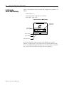
1
DeviceNet PCI
Communication
Interface Card
1784-PCIDS, -CPCIDS
User Manual
Important User Information
Because of the variety of uses for the products described in this
publication, those responsible for the application and use of this
control equipment must satisfy themselves that all necessary steps
have been taken to assure that each application and use meets all
performance and safety requirements, including any applicable laws,
regulations, codes and standards.
The illustrations, charts, sample programs and layout examples shown
in this guide are intended solely for purposes of example. Since there
are many variables and requirements associated with any particular
installation, Allen-Bradley does not assume responsibility or liability
(to include intellectual property liability) for actual use based upon
the examples shown in this publication.
Allen-Bradley publication SGI-1.1, Safety Guidelines for the
Application, Installation and Maintenance of Solid-State Control
(available from your local Allen-Bradley office), describes some
important differences between solid-state equipment and
electromechanical devices that should be taken into consideration
when applying products such as those described in this publication.
Reproduction of the contents of this copyrighted publication, in whole
or part, without written permission of Rockwell Automation, is
prohibited.
Throughout this manual we use notes to make you aware of safety
considerations:
ATTENTION
!
Identifies information about practices or
circumstances that can lead to personal injury or
death, property damage or economic loss
Attention statements help you to:
• identify a hazard
• avoid a hazard
• recognize the consequences
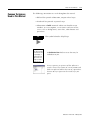
IMPORTANT
Identifies information that is critical for successful
application and understanding of the product.
Allen-Bradley and Data Highway Plus are trademarks of Rockwell Automation.
DeviceNet is a trademark of Open Device Vendors Association (ODVA).
Ethernet is a trademark of Digital Equipment Corporation, Intel, and Xerox Corporation.
SoftLogix 5 and RSNetworx for DeviceNet are trademarks of Rockwell Software.
Windows NT is a trademark of Microsoft Corporation.
European Communities (EC)
Directive Compliance
If this product has the CE mark it is approved for installation within
the European Union and EEA regions. It has been designed and tested
to meet the following directives.
EMC Directive
This product is tested to meet the Council Directive 89/336/EC
Electromagnetic Compatibility (EMC) by applying the following
standards, in whole or in part, documented in a technical construction
file:
• EN 50081-2 EMC — Generic Emission Standard, Part 2 —
Industrial Environment
• EN 50082-2 EMC — Generic Immunity Standard, Part 2 —
Industrial Environment
This product is intended for use in an industrial environment.
Low Voltage Directive
This product is tested to meet Council Directive 73/23/EEC Low
Voltage, by applying the safety requirements of EN 61131-2
Programmable Controllers, Part 2 - Equipment Requirements and
Tests. For specific information required by EN 61131-2, see the
appropriate sections in this publication, as well as the Allen-Bradley
publication Industrial Automation Wiring and Grounding Guidelines
For Noise Immunity, publication 1770-4.1.
This equipment is classified as open equipment and must be mounted
in an enclosure during operation to provide safety protection.
Preface
About This User Manual
Introduction
This manual applies to both the 1784-PCIDS and 1784-CPCIDS
communication interface cards. These cards provide DeviceNet
configuration and I/O scan capabilities and are functionally
equivalent. In the screen shots and examples in this manual, we
reference the 1784-PCIDS scanner, but understand that the
1784-CPCIDS scanner can be used in the same way.
This manual provides an example network that demonstrates how to
configure a DeviceNet network using the 1784-PCIDS card and
RSNetWorx for DeviceNet™ software.
This manual describes how:
• to install and configure your 1784-PCIDS card
• to configure the DeviceNet network and map I/O data using
RSNetWorx for DeviceNet software
• to test and verify your DeviceNet network
This manual is designed to provide you enough information to get the
example network up and running. Use this manual if you are
knowledgeable about DeviceNet networks, but may not have
experience interfacing them to PCI- or CPCI-bus computers. The
information provided is a base; modify or expand the examples to suit
your particular needs.
Audience
This manual is intended for control engineers and technicians who are
installing, programming, and maintaining a control system that
includes communicating with a DeviceNet network using a PCI-bus
computer through a 1784-PCIDS card or using a compact PCI-bus
computer through a 1784-CPCIDS card.
We assume that you:
• are developing a DeviceNet network using a personal computer
in conjunction with a 1784-PCIDS, -CPCIDS card
• know each of your device’s I/O parameters and requirements
• are experienced with the Microsoft® Windows™ environment
• are familiar with RSNetWorx for DeviceNet software
1
Publication 1784-6.5.30 - February 2001
P-2
About This User Manual
The Example Network
This manual describes how to set up an example network. The
manual provides examples of each step of the setup, with references
to other manuals for more details.
System Components
We used the following devices and software for the example network
in this manual. For your own application, substitute your own devices
to fit your needs. The recommended configurations in this user
manual will help you set up the test system and get it working. Your
eventual configuration will depend on your application.
Note: If you use different software versions of these products some of
your screens may appear different from those shown in the examples.
Product Name
Qty
Catalog Number
Version
Hardware
1
DeviceNet PCI communication interface card
1784-PCIDS
2.002
1
RediSTATION Operator Interface
2705-T3DN1A42A
1
Series 9000 Photoeye
42GNP-9000 or equivalent
-
1
24V Power Supply
any regulated 24VDC, 8A
-
1
PC
IBM-compatible PCI-bus architecture
Windows NT 4.0, Service Pack 5 or
later
-
DeviceNet dropline or trunkline
cables and connectors, as needed
1787-PCABL, -TCABL, -MCABL
-
-
Software
Publication 1784-6.5.30 - February 2001
RSNetWorx for DeviceNet
9357-DNETL3,
2.22
RSLinx/RSLinx Gateway
9355-WAB
2.20
IOLinx
(supplied with 1784-PCIDS card)
1.14
About This User Manual
Common Techniques
Used in This Manual
P-3
The following conventions are used throughout this manual:
• Bulleted lists provide information, not procedural steps.
• Numbered lists provide sequential steps.
• Information in bold contained within text identifies menu
windows, or screen options, screen names and areas of the
screen, such as dialog boxes, status bars, radio buttons and
parameters.
TIP
This is a definition
box. When a word is
bold within the text
of a paragraph, a
definition box will
appear in the left
margin to further
define the text.
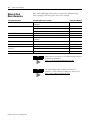
This symbol identifies helpful tips.
A definition box defines terms that may be
unfamiliar to you.
Screen captures are pictures of the software’s
actual screens. The names of screen buttons and
fields are often in bold in the text of a procedure.
Pictures of keys represent the actual keys you
press.
Publication 1784-6.5.30 - February 2001
P-4
About This User Manual
Where to Find
More Information
Refer to the following publications as needed for additional help
when setting up and using your DeviceNet network:
For information about
See this publication or product
Publication Number
the 1784-PCIDS DeviceNet Scanner Card
DeviceNet PCI Communication Interface Card Installation
Instructions
1784-5.31
DeviceNet
DeviceNet System Overview
DN-2.5
DeviceNet Cable Planning and Installation Manual
DN-6.7.2
DeviceNet Cable Planning and Installation Release Note 1
DN-6.7.2-RN1
the RediSTATION
RediSTATION Operator Interface User Manual
2705-804
the 9000 Series Photoeye
{refer to the information that came with your photoeye}
n/a
IOLinx software
DeviceNet PCI Communication Interface Card Installation
Instructions
1784-5.31
RSLinx software
RSLinx Lite User’s Guide
9399-WAB32LUG
RSNetWorx for DeviceNet software
Getting Results with RSNetWorx for DeviceNet
9399-DNETGR
Developing your own Visual Basic or C++
application
IOLinx Software Development Kit
9230-IOLINXSDK
IOLinx SDK Data Sheet
NETS-SP-010C-US-E
terms and definitions
Allen-Bradley Industrial Automation Glossary
AG-7.1
Publication 1784-6.5.30 - February 2001
TIP
Many of these manuals are available online from the
Automation Bookstore:
http://www.theautomationbookstore.com.
TIP
For more information on Rockwell Software
products, visit the Rockwell Software internet site:
http://www.software.rockwell.com.
About This User Manual
Terminology
This term
P-5
Means
Change of State A type of I/O data communication. The scanner module can send and
receive data with slave devices that have the change of state feature.
Data is sent either whenever a data change occurs, or at the rate of the
heartbeat if no data has changed.
Cyclic
A type of I/O data communication. The scanner can send and receive data
with slave devices that have the cyclic feature. Data is only sent at a
user-configurable rate.
Dual Mode
The scanner is in dual mode when it serves as a master to one or more
slaves and as a slave to another master simultaneously.
EDS
Electronic Data Sheet. A vendor-supplied template that specifies how
information is displayed as well as what is an appropriate entry (value).
EPR
Expected Packet Rate. One quarter of the time in milliseconds that the
scanner must wait to hear from a device before deciding the connection
has failed.
Explicit
Messaging
Messaging protocol that states the meaning of the message. This
protocol commands the performance of a particular task and returns the
results of the task performance to the requestor. Used for lower priority
tasks, such as configuration and data monitoring.
Heartbeat Rate This only applies to change of state messaging.
Devices that are configured for change of state data also send a
“heartbeat” signal to indicate the device is still operating on the network
even if no data has changed.
Host Platform
The computer in which the 1784-family scanner is installed.
I/O
An abbreviation for “input and output.”
Implicit
Messaging
The type of messaging used for high priority I/O control data; e.g., change
of state, cyclic, polled, or strobed.
Input Data
Data produced by a DeviceNet device and collected by the scanner for a
host platform to read.
MAC ID
The network address of a DeviceNet node.
Network
The DeviceNet network or the RSNetWorx for DeviceNet software
representation of the network.
Node
Hardware that is assigned a single address on the network (also referred
to as device).
Offline
When the RSNetWorx is not communicating on the network.
Online
When RSNetWorx is configured and enabled to communicate on the
network.
Output Data
Data that is produced by a host application and written to the scanner’s
memory. This data is sent by the scanner to DeviceNet devices.
PC
Abbreviation for an IBM® compatible personal-computer.
Polled
A type of input/output-data communication. A polled message solicits a
response from a single, specified device on the network (a point-to-point
transfer of data).
Record
The node address and channel-specific memory assigned in the scanner’s
non-volatile storage for a node in the scanlist.
Rx
An abbreviation for “receive”.
Scanlist
The list of devices (nodes) with which the scanner is configured to
exchange I/O data.
Scanner
The function of the 1784-family scanner to support the exchange of I/O
with slave modules.
Publication 1784-6.5.30 - February 2001
P-6
About This User Manual
Rockwell Automation
Support
Slave Mode
The scanner is in slave mode when it is placed in another module’s
scanlist as a slave device. This is used to share data between scanners.
Strobed
A type of I/O data communication. A strobed message solicits a response
from each strobed device (a multicast transfer). It is a 64-bit message that
contains one bit for each device on the network.
Tx
An abbreviation for “transmit”.
Rockwell Automation offers support services worldwide, with over 75
sales/support offices, 512 authorized distributors, and 260 authorized
systems integrators located throughout the United States alone, plus
Rockwell Automation representatives in every major country in the
world.
Local Product Support
Contact your local Rockwell Automation representative for:
•
•
•
•
sales and order support
product technical training
warranty support
support service agreements
Technical Product Assistance
If you need to contact Rockwell Automation for technical assistance,
call your local Rockwell Automation representative, or call Rockwell
directly at: 1 440 646-5800.
For presales support, call 1 440 646-3NET.
You can obtain technical assistance online from the following
Rockwell Automation WEB sites:
• www.ab.com/mem/technotes/kbhome.html (knowledge base)
• www.ab.com/networks/eds (electronic data sheets)
Your Questions or Comments about This Manual
If you find a problem with this manual, please notify us of it on the
enclosed Publication Problem Report (at the back of this manual).
Publication 1784-6.5.30 - February 2001
About This User Manual
P-7
If you have any suggestions about how we can make this manual
more useful to you, please contact us at the following address:
Rockwell Automation, Allen-Bradley Company, Inc.
Control and Information Group
Technical Communication
1 Allen-Bradley Drive
Mayfield Heights, OH 44124-6118
Publication 1784-6.5.30 - February 2001
P-8
About This User Manual
Publication 1784-6.5.30 - February 2001
Table of Contents
Chapter 1
Before You Begin
What This Chapter Contains . . . . . . . . . . . . . . . . . . . . . . . . . . . .
What You Need to Know . . . . . . . . . . . . . . . . . . . . . . . . . . . . . .
What Your 1784-PCIDS Card Does. . . . . . . . . . . . . . . . . . . . . . . .
Communicating with Your Devices . . . . . . . . . . . . . . . . . . . . . . .
Communicating with Your Host Application. . . . . . . . . . . . . . . . .
What Scanner Data Tables Are and What They Do . . . . . . . . . . . .
RSNetWorx Software as a Configuration Tool . . . . . . . . . . . . . . . .
RSNetWorx for DeviceNet Tutorial . . . . . . . . . . . . . . . . . . . . . . . .
What’s Next? . . . . . . . . . . . . . . . . . . . . . . . . . . . . . . . . . . . . . . . .
1-1
1-1
1-2
1-5
1-6
1-7
1-7
1-7
1-8
Chapter 2
Planning Your Configuration and
Data Mapping Your Devices
What This Chapter Contains . . . . . . . . . . . . . . . . . . . . . . . . . . . .
What You Need to Know . . . . . . . . . . . . . . . . . . . . . . . . . . . . . .
Beginning the Process . . . . . . . . . . . . . . . . . . . . . . . . . . . . . . . . .
The Example Network. . . . . . . . . . . . . . . . . . . . . . . . . . . . . . . . .
Example Network Devices . . . . . . . . . . . . . . . . . . . . . . . . . . .
RediSTATION Operator Interface Data Mapping . . . . . . . . . . .
Mapping RediSTATION Input Data. . . . . . . . . . . . . . . . . . . . .
Mapping RediSTATION Output Data . . . . . . . . . . . . . . . . . . .
Photoeye Input Data Mapping . . . . . . . . . . . . . . . . . . . . . . . .
Mapping Photoeye Input Data . . . . . . . . . . . . . . . . . . . . . . . .
What’s Next? . . . . . . . . . . . . . . . . . . . . . . . . . . . . . . . . . . . . . . . .
2-1
2-1
2-1
2-2
2-2
2-4
2-5
2-6
2-7
2-8
2-8
Chapter 3
Setting Up the Hardware
for the Example Network
What This Chapter Contains . . . . . . . . . . . . . . . . . . . . . . . . . . . .
Installing the 1784-PCIDS Card . . . . . . . . . . . . . . . . . . . . . . . . . .
Accessing the Computer’s Expansion Slots . . . . . . . . . . . . . . .
Inserting the Card . . . . . . . . . . . . . . . . . . . . . . . . . . . . . . . . .
Connecting the Card to the DeviceNet Network . . . . . . . . . . .
Installing the RediSTATION Operator Interface. . . . . . . . . . . . . . .
Installing the Series 9000 Photoeye . . . . . . . . . . . . . . . . . . . . . . .
How the Example System Should Look . . . . . . . . . . . . . . . . . . . .
What’s Next? . . . . . . . . . . . . . . . . . . . . . . . . . . . . . . . . . . . . . . . .
3-1
3-1
3-2
3-3
3-3
3-5
3-6
3-7
3-7
Chapter 4
Configuring the
DeviceNet Network
i
What This Chapter Contains . . . . . . . . . . . . . . . . . . . . . . . . . . . . 4-1
Required Software. . . . . . . . . . . . . . . . . . . . . . . . . . . . . . . . . . . . 4-1
Installing the Software . . . . . . . . . . . . . . . . . . . . . . . . . . . . . . . . . 4-2
Configuring the RSLinx 1784-PCIDS DeviceNet Driver. . . . . . . . . . 4-2
Configuration Screen Map . . . . . . . . . . . . . . . . . . . . . . . . . . . . . . 4-7
Setting Up an Online Connection. . . . . . . . . . . . . . . . . . . . . . . . . 4-8
Configuring the I/O Devices . . . . . . . . . . . . . . . . . . . . . . . . . . . 4-10
Verifying the Photoeye Configuration . . . . . . . . . . . . . . . . . . 4-14
Verifying the RediSTATION Configuration . . . . . . . . . . . . . . 4-15
AutoMapping the Devices into the Scanlist . . . . . . . . . . . . . . 4-16
Downloading the Configuration to the Scanner. . . . . . . . . . . 4-19
What’s Next? . . . . . . . . . . . . . . . . . . . . . . . . . . . . . . . . . . . . . . . 4-19
Publication 1784-6.5.30 - February 2001
Table of Contents
ii
Chapter 5
Using IOLinx To Test
the Example Network
What This Chapter Contains . . . . . . . . . . . . . . . . .
Using IOLinx to Configure the 1784-PCIDS Port . . .
Testing the DeviceNet Network . . . . . . . . . . . . . . .
Using the IOLinx Device Status Screen . . . . . . .
Testing the RediSTATION and Photoeye Inputs
Testing the RediSTATION Output. . . . . . . . . . .
.
.
.
.
.
.
.
.
.
.
.
.
.
.
.
.
.
.
.
.
.
.
.
.
.......
.......
.......
.......
.......
.......
5-1
5-1
5-4
5-6
5-7
5-8
Appendix A
Diagnostics
and Troubleshooting
What This Appendix Contains . .
I/O Status Indicator . . . . . . . . . .
Module (MOD) Status Indicator .
Network (NET) Status Indicator .
.
.
.
.
.
.
.
.
....
....
....
....
..................
..................
..................
..................
A-1
A-1
A-2
A-2
What This Appendix Contains . . . . . . . . . . . . . . . . . . . . . . . . . .
Configuring the RSLinx SoftLogix 5 Driver . . . . . . . . . . . . . . . . .
Configuring the SoftLogix 5 DeviceNet Driver. . . . . . . . . . . . . . .
Putting the SoftLogix Controller in Remote Mode . . . . . . . . . . . .
Creating the Example Application Program . . . . . . . . . . . . . . . .
Downloading the Program. . . . . . . . . . . . . . . . . . . . . . . . . . . . .
Running the Example Program . . . . . . . . . . . . . . . . . . . . . . . . .
B-1
B-2
B-4
B-6
B-7
B-10
B-11
Appendix B
Creating and Running
a SoftLogix 5 Application
Appendix C
Configuring the DeviceNet
Network from Another Network
What This Appendix Contains . . . . . . . . . . . . . . . . . . . . . . . . . . . C-1
Configuring the DeviceNet Network Via a ControlLogix Gateway . C-2
Configuring the DeviceNet Network Via an RSLinx Gateway . . . . . C-5
Appendix D
Changing the Network
Baud Rate
Index
Publication 1784-6.5.30 - February 2001
Required Procedure. . . . . . . . . . . . . . . . . . . . . . . . . . . . . . . . . . D-1
Chapter
1
Before You Begin
What This Chapter Contains
What You Need to Know
This chapter provides an overview of communication between a
personal computer running the host application and DeviceNet
devices via a 1784-PCIDS card. The following table identifies where to
find specific information.
For information about
See page
What You Need to Know
1-1
What Your 1784-PCIDS Card Does
1-2
Communicating with Your Devices
1-5
Communicating with Your Host Application
1-6
What Scanner Data Tables Are and What They Do
1-7
RSNetWorx Software as a Configuration Tool
1-7
RSNetWorx for DeviceNet Tutorial
1-7
Before configuring your 1784-PCIDS card, you must understand:
• the data exchange between a host application and DeviceNet
devices through the 1784-PCIDS card
• user-configurable scanner module data tables
• the role of RSNetWorx for DeviceNet software
• the role of IOLinx software
1
Publication 1784-6.5.30 - February 2001
1-2
Before You Begin
What Your 1784-PCIDS
Card Does
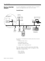
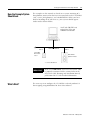
In a typical configuration, the 1784-PCIDS card acts as an interface
between a host application and the DeviceNet network.
DeviceNet Network
1784-CPCIDS
scanner card
Workstation PC with
Host Application
Laptop with RSLinx and/or
RSNetWorx for DeviceNet
1784-PCD card
1784-PCIDS
scanner card
DeviceNet Network
1794-ADN
FLEX I/O
Series 9000
Photoeye
ControlLogix with
1756-DNB module
RediSTATION
1305 Drive
The interface card communicates with DeviceNet devices over the
network to:
•
•
•
•
read inputs from a device
write outputs to a device
download configuration data
monitor a device’s operational status
The scanner engine in the PCIDS communicates with the host
application in the form of Input, Output, and Diagnostic Tables.
Information exchanged includes:
• device I/O data
• status information
• configuration data
Publication 1784-6.5.30 - February 2001
Before You Begin
1-3
An I/O DeviceNet configuration is shown in the following figure. See
the referenced chapters for more information.
I/O DeviceNet Configuration
Industrial workstation
with 1784-PCIDS scanner,
running RSLinx and
RSNetWorx for DeviceNet
Configuring Scanner Card (Chapter 4)
Mapping Data Tables (Chapters 2 and 4)
Testing the Network (Chapter 5)
PCIDS
Configuration Data
from scanner to Device
(Chapter 4)
Output Data to Device
from scanner (Chapters 2 & 5)
DeviceNet Network
Input
Device
Input Data from
Device to scanner
(Chapters 2 & 5)
Output
Device
Publication 1784-6.5.30 - February 2001
1-4
Before You Begin
The 1784-PCIDS card can be used within the RSLinx Gateway
architecture to bridge a DeviceNet network to another network, such
as Ethernet (shown below) or Data Highway Plus.
Configuring Devices and Data Collection on Higher
Level Networks Using RSLinx Gateway Architecture
Gateway Client running
RSLinx and RSNetWorx for
DeviceNet
Ethernet Network
RSLinx Gateway Server
Configuration of device using
RSNetWorx for DeviceNet
(Chapter 4 & Appendix C)
1784-PCIDS Collection of status or
alarm data (Chapter 5,
Appendix B)
DeviceNet Network
Target Device to
be configured
Publication 1784-6.5.30 - February 2001
Source Device
to collect data
Before You Begin
Communicating with Your
Devices
A strobe message is a
multicast transfer of data
(which is 64 bits in length)
sent by the scanner that
solicits a response from each
strobed slave device. There
is one bit for each of the
possible 64 node addresses.
The devices respond with
their data, which can be as
much as 8 bytes.
Your scanner communicates with a device via strobe, poll, change of
state, and/or cyclic messages. It uses these messages to solicit data from
or deliver data to each device. Data received from the devices, or input
data, is organized by the scanner and made available to your host
application. Data received from your host application, or output data, is
organized in the scanner and sent on to your devices.
IMPORTANT
A cyclic message is sent only
at a user-configurable rate,
such as every 10 ms.
Throughout this document, input and output are
defined from the host application’s point of view.
Output is data sent from the host application to a
device. Input is data collected by the host application
from a device.
All data is sent and received on a DeviceNet network
in byte lengths. A device may, for example, produce
only two bits of input information. But since the
minimum data size is one byte, the two bits of
information are embedded in a full byte of data sent
by the device. In this case, the other six bits are
insignificant.
A poll message is a
point-to-point transfer of
data (0-255 bytes) sent by
the scanner that solicits a
response from a single
device. The device responds
with its input data (0-255
bytes).
A change of state message
is a transfer of data sent
whenever a data change
occurs. A user-configurable
heartbeat rate can also be
set to allow devices to
indicate proper operation
during intervals between
data changes. This does not
solicit response data, but
may receive an acknowledge
message.
1-5
DeviceNet Devices
1784-PCIDS Card
Input Data From
DeviceNet Devices
Input Data Storage
Data from a single device can
be mapped to separate scanner
memory locations. For example,
“On/Off” values can be mapped
to one location, diagnostic
values to another, etc. This is
known as “map segmenting.”
This concept is illustrated by
word A, stored as separate
bytes A1 and A2
A1
Word
0
B
1
C
A2
D
E
E
A2
A1
input from the
2 devices to the
3 host application
4
B
5
D
C
6
E
Output Data To
DeviceNet Devices
Output Data Storage
X
X
Y
Y
output from
the host application
Y
Y
Y
Y
Y
Z
Z
Publication 1784-6.5.30 - February 2001
1-6
Before You Begin
Communicating with Your
Host Application
Your host application communicates with the scanner via input and
output image tables. Input data, gathered from the network’s
devices, is organized within the scanner and made available for the
host application to “read” from the input image table.
The scanner does not send data to your host application. Data
transferred between the scanner and the host application must be
initiated by the host application. Output data is sent, or “written,” to
the scanner by your host application by placing the data in the output
image table. This data is organized in the scanner, which in turn
passes the data on to your scanned devices via strobe, poll, change of
state, or cyclic messages.
Host Application
1784-PCIDS Card
Internal Input
Data Storage
A1
Input/Output Data File
C
A2
I/O Map
Data
Transfer
Read
D
E
E
B
C
A2
D
E
E
Input from
the devices
Internal Output
Data Storage
Z
Y
Y
Y
Y
I/O Map
X
Y
Data
Transfer
Write
Y
Y
Y
Z
Publication 1784-6.5.30 - February 2001
Output to
the devices
Before You Begin
What Scanner Data Tables
Are and What They Do
1-7
To manage the flow of I/O data between your host application and
the network devices, the scan engine inside the 1784-PCIDS card uses
the following data tables:
• Scanner Configuration Table
• Scan List Table
• Device Input Data Table
• Device Output Data Table
• Device Idle Table
• Device Failure Table
You can configure these data tables through RSNetWorx software.
RSNetWorx Software as
a Configuration Tool
RSNetWorx for DeviceNet software is used to configure the scanner’s
data tables in our example. This software tool connects to the scanner
locally (or remotely if you wish) over the DeviceNet network via the
1784-PCIDS card.
TIP
RSNetWorx for DeviceNet
Tutorial
RSNetWorx for DeviceNet software can also
configure the scanner from a remote location via a
gateway. See Appendix C.
RSNetWorx for DeviceNet software comes with a tutorial which will
guide you through the configuration process. Please refer to the
tutorial if you have any questions about the configuration process
described in this manual.
Publication 1784-6.5.30 - February 2001
1-8
Before You Begin
What’s Next?
The remaining sections of this manual provide the following
information:
• Chapter 2 covers the configuration process planning stage
through a data mapping example.
• Chapter 3 describes the hardware setup for the example
network.
• Chapter 4 covers configuration of the DeviceNet network using
RSNetWorx for DeviceNet software.
• Chapter 5 describes how to test the network.
Publication 1784-6.5.30 - February 2001
Chapter
2
Planning Your Configuration and Data
Mapping Your Devices
What This Chapter Contains
What You Need to Know
This chapter introduces questions you should ask before configuring
your 1784-PCIDS card. In addition, it presents an example DeviceNet
network and I/O data mapping scheme for a photoeye and a
RediSTATION operator interface module. The following table
identifies what this chapter covers and where to find specific
information.
For information about
See page
What You Need to Know
2-1
Beginning the Process
2-1
The Example Network
2-2
Example Network Devices
2-2
Photoeye Input Data Mapping
2-7
Mapping Photoeye Input Data
2-8
RediSTATION Operator Interface Data Mapping
2-4
Mapping RediSTATION Input Data
2-5
Mapping RediSTATION Output Data
2-6
To map data via your 1784-PCIDS communication interface card, you
must understand:
• your network requirements
• how input data is mapped
• how output data is mapped
Beginning the Process
Planning before configuring your 1784-PCIDS communication
interface card helps make sure that you can:
• use your memory and bandwidth efficiently
• cater to device-specific needs and requirements
• give priority to critical I/O transfers
• leave room for expansion
1
Publication 1784-6.5.30 - February 2001
2-2
Planning Your Configuration and Data Mapping Your Devices
A very important question to answer is “what is on your network?”
You should be familiar with each device’s:
• communication requirements
• I/O importance and size
• frequency of message delivery
You should also ask “how might this network appear in the future?” At
this point in your planning, it is advantageous for you to have some
idea of how the network could be expanded. I/O data mapping can
be performed automatically by the RSNetWorx software. But when
mapping your I/O, you also have the opportunity to allot room for
future I/O. This can save time and effort in the future.
For example, RSNetWorx will automatically map the devices as
efficiently as possible, but the result is that multiple devices may share
parts of the same word in memory (e.g., Device “A” may be mapped
to the upper 8 bits and Device “B” to the lower 8 bits). However, you
can also have the system map the devices such that no two devices
share the same word by selecting the “word align” option when
performing automapping. You can manually map the devices if you
need to assign them to specific memory locations.
For details refer to the Help screens provided by the RSNetWorx for
DeviceNet software. Additional support can be found at the Rockwell
Software website: http://www.software.rockwell.com.
The Example Network
The following example illustrates a data mapping plan for a
DeviceNet network. Note that even if the mapping is performed
automatically by the RSNetWorx software, you must know where the
devices are mapped in order to use them in your application.
Example Network Devices
This example network has the following devices:
• a PC host platform running RSNetWorx for DeviceNet software
• a 1784-PCIDS scanner card interfacing the host application with
a DeviceNet network
• a Series 9000 photoelectric sensor (strobed)
• a RediSTATION operator interface (polled)
• a 24 volt DC power supply
Publication 1784-6.5.30 - February 2001
Planning Your Configuration and Data Mapping Your Devices
IMPORTANT
2-3
In the following example, output is data sent to a
device from the host application Input is data
collected from a device by the host application.
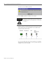
The example DeviceNet system we will set up is shown below:
Host Platform with
RSLinx, IOLinx, and
RSNetWorx for
DeviceNet
1784-PCIDS
Scanner Card
Node 0
∗
∗
DeviceNet Network
Node 9
Node 7
RediSTATION
Operator Interface
Series 9000
Photoelectric
Sensor
* See note below
IMPORTANT
Each end of the DeviceNet trunk cable must be
properly terminated with a resistor. Refer to the
DeviceNet Cable Planning and Installation Manual,
publication DN-6.7.2 for detailed information.
Publication 1784-6.5.30 - February 2001
2-4
Planning Your Configuration and Data Mapping Your Devices
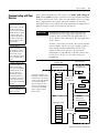
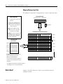
RediSTATION Operator Interface Data Mapping
The RediSTATION has both inputs and outputs that must be mapped.
The input byte is mapped to the 1784-PCIDS scanner’s input data
table. The output byte is mapped to the 1784-PCIDS scanner’s output
data table.
The mapping procedure, using RSNetWorx for DeviceNet software, is
described on pages 4-16 to 4-18.
RediSTATION operator interface
Two input bits from the RediSTATION will
be mapped: bit 1 for the green Start button
and bit 0 for the red Stop button.
Indicator light
green start light
Bit 4 of the input byte indicates if the bulb
is burnt out.
start bit (green button)
red start light
The RediSTATION
operator interface
produces one byte of
input data and uses one
byte of output data.
input
B
7
6
5
4
G R
3
2
1
output
0
L
7
6
5
4
3
2
1
stop bit
(red button)
indicator light
energize bit
0
One output bit for the RediSTATION’s
indicator light (on/off) will be mapped.
In the RediSTATION’s bits for the red and green buttons and the
indicator light energize bit:
• 1 = ON
• 0 = OFF
Publication 1784-6.5.30 - February 2001
Planning Your Configuration and Data Mapping Your Devices
2-5
Mapping RediSTATION Input Data
The RediSTATION operator interface’s input byte is mapped to the
scanner’s input data table.
RediSTATION Input Byte
start/stop station node address 7
What’s Happening?
The operator presses the green
start or red stop button.
1
B
R = bit for red button (STOP)
G = bit for green button (START)
G R
The bits for the RediSTATION
operator interfaces’s red and green
buttons are mapped into the
scanner’s data table. The “R” or
“G” bit turns on.
= unused bits
1
2 The host application reads word
zero into its input data file and
reacts accordingly.
1784-PCIDS Scanner Input Image Table1
Important: The scanner only makes the
data file available for the host
application to read. The scanner does
not move the data file to the host
application.
B
G
R
Word 0
Word 1
Word 2
Host Application
Input Data File
Word 3
Word 0
0000 0000 000B 00GR
Word 1
0000 0000 0000 0000
Word 2
0000 0000 0000 0000
Word 3
0000 0000 0000 0000
Word 4
0000 0000 0000 0000
Word 5
0000 0000 0000 0000
2
Example: The green START button from
the RediSTATION appears in word 0, bit 1
in the host application’s input data file.
Word 4
Word 5
up to
Word 1023
The red STOP button appears in word 0,
bit 0 in the host application’s input data
file.
1This mapping is based upon the example in chapter 5.
The mapping for your system may be different.
Publication 1784-6.5.30 - February 2001
2-6
Planning Your Configuration and Data Mapping Your Devices
Mapping RediSTATION Output Data
The RediSTATION operator interface’s output byte is mapped to the
scanner’s output data table. Within the output byte is bit 0 for the
indicator light. The output data file is then transferred from the host
application to turn the light on or off.
RediSTATION Output Byte
What’s Happening?
start/stop station node address 7
The host application writes to bit
0 (“L”) of word 0 in its Output
Data File.
1
2
L
The indicator light bit for the
RediSTATION is mapped to the
scanner’s output data table.
2
The output image table is then
sent to the RediSTATION via a
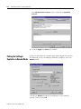
poll message from which the
RediSTATION receives its
indicator light bit.
L = bit for the station
indicator light
= unused bits
1784-PCIDS Scanner Output Image Table1
L
The RediSTATION indicator light
then turns on or off.
Word 0
Word 1
Word 2
Host Application
Output Data File
Word 3
Word 0
0000 0000 0000 000L
Word 1
0000 0000 0000 0000
Word 2
0000 0000 0000 0000
Word 3
0000 0000 0000 0000
Word 4
0000 0000 0000 0000
Word 5
0000 0000 0000 0000
1
Example: The RediSTATION’s indicator
light (L) is taken from word 0, bit 0 in
the host application’s output image
table.
1This mapping is based upon the example in chapter 5.
The mapping for your system may be different.
Publication 1784-6.5.30 - February 2001
Word 4
Word 5
up to
Word 1023
Planning Your Configuration and Data Mapping Your Devices
2-7
Photoeye Input Data Mapping
The photoelectric sensor (photoeye) inputs are mapped to the
1784-PCIDS scanner’s input data table. The mapping procedure using
RSNetWorx for DeviceNet software is described on pages 4-16 to 4-17.
The photoeye has no outputs to map.
Series 9000 Photoeye
Two input bits from the photoeye
will be mapped: the status bit
and the data bit.
The photoeye produces
one byte of input data in
response to the strobe
message.
status
bit
S D
input
7
6
5
4
3
2
1
data
bit
0
Publication 1784-6.5.30 - February 2001
2-8
Planning Your Configuration and Data Mapping Your Devices
Mapping Photoeye Input Data
The photoeye’s input byte is mapped to the scanner’s input data table.
Photoeye Input Byte
What’s Happening?
photoelectric sensor node address 9
An object passes in front of the
photoeye.
S D
1 The status and data bits from
the photoeye are mapped into
the scanner’s input data table.
- Bit 8 (“D”) turns on.
= unused bits
1
2
The host application reads
word zero into its input data
file and reacts accordingly.
1784-PCIDS Scanner Input Image Table1
Important: The scanner only makes the
data available for the host application to
read. The scanner does not move the
data to the host application.
S D
RediSTATION input byte
Word 0
Word 1
Host application
Input Data File
Word 2
Word 0
0000 00SD 0000 0000
Word 3
Word 1
0000 0000 0000 0000
Word 2
0000 0000 0000 0000
Word 3
0000 0000 0000 0000
Word 4
0000 0000 0000 0000
Word 5
0000 0000 0000 0000
2
Word 4
Word 5
up to
Example: The Data bit from the photoeye
appears in word 0, bit 8 in the host
application’s input image table.
Word 1023
The Status bit from the photoeye appears in
word 0, bit 9 in the host application’s input
image table.
1This mapping is based upon the example in chapter 5.
The mapping for your system may be different.
What’s Next?
Publication 1784-6.5.30 - February 2001
Chapter 3 describes how to set up the system hardware for the
example network.
Chapter
3
Setting Up the Hardware
for the Example Network
What This Chapter Contains
This chapter describes how to set up the DeviceNet hardware for the
example network. The following table describes what this chapter
contains and where to find specific information.
Note that the example network uses a 1784-PCIDS card. The steps for
setting up a network using a 1784-CPCIDS card will differ slightly.
For information about
3-1
Accessing the Computer’s Expansion Slots
3-2
Inserting the Card
3-3
Connecting the Card to the DeviceNet Network
3-3
Installing the RediSTATION Operator Interface
3-5
Installing the Series 9000 Photoeye
3-6
How the Example System Should Look
3-7
IMPORTANT
Installing the
1784-PCIDS Card
See page
Installing the 1784-PCIDS Card
Rockwell recommends that you install all PCI cards
first, before you install any ISA cards in your
computer.
This section provides basic information on installing the 1784-PCIDS
card.
You need a PCI-bus based personal computer with:
• Windows NT 4.0 with Service Pack 5(1) or later
• one open PCI slot
• approximately 2 MB available disk space
For detailed information refer to the DeviceNet PCI Communication
Interface Card Installation Instructions, publication 1784-5.31.
(1)
1
Required by SoftLogix 5.
Publication 1784-6.5.30 - February 2001
3-2
Setting Up the Hardware for the Example Network
ATTENTION
!
The PCIDS card uses CMOS technology, which is
highly sensitive to electrostatic discharge (ESD). ESD
may be present whenever you are handling the card.
Handling a card without any EDS protection can
cause internal circuit damage that may not be
apparent during installation or initial use.
Take these precautions to guard against electrostatic
damage:
• Before handling the card, be sure to touch a
grounded object such as a PC’s metal chassis to
discharge any built-up static charge.
• Avoid touching the backplane connector or
interface connector pins.
• When the card is not in use, store it in the
anti-static bag in which it was shipped.
IMPORTANT
Remember, a computer with AC power disconnected
is not a grounded object.
Make sure you know how to:
• install hardware in your computer
• configure the computer’s options before you install the PCID(S)
Consult your computer’s documentation for specific information.
To install the card:
1. Gain access to the computer’s expansion slots.
2. Insert the card into an open PCI slot in the computer.
Accessing the Computer’s Expansion Slots
To install the PCIDS card, you must access the computer’s expansion
slots. Refer to your computer’s user guide for instructions on how to:
• Power down the host computer by turning off the power switch
• Remove the computer’s cover
• Locate a vacant PCI expansion slot
• Remove the slot’s expansion cover
Publication 1784-6.5.30 - February 2001
Setting Up the Hardware for the Example Network
3-3
Inserting the Card
To insert the card inside the computer:
1. Follow the card handling instructions on page 3-2.
2. Insert the PCIDS card into the edge connector and tighten the
expansion slot screw.
3. Connect the card to the DeviceNet Network as described in the
following section.
Connecting the Card to the DeviceNet Network
ATTENTION
!
Do not wire your 1784-PCIDS card with power
applied to your network. You may short circuit your
network or disrupt communication.
Perform the following steps to connect your 1784-PCIDS card to the
DeviceNet network:
1. Connect the DeviceNet drop line to the 5-pin DeviceNet connector
provided with the card. Match the wire insulation colors to the
colors shown on the label.
BLACK
BLUE
BARE
WHITE
RED
Wire Color
Symbol
Description
Black
V-
24V DC power return
Blue
CAN_L
Data Low - Data Line
Bare
DRAIN
Shield
White
CAN_H
Data High - Data Line
Red
V+
+24V DC
2. Locate the DeviceNet port on the card.
Publication 1784-6.5.30 - February 2001
3-4
Setting Up the Hardware for the Example Network
3. Insert the DeviceNet connector into the five-pin header.
Module label shows
wiring color scheme
4. Apply power to the DeviceNet network, and turn on the computer
to make sure it powers up correctly.
IMPORTANT
If the computer does not power up correctly, check
to make sure that the card is correctly inserted into
the slot. Also check the computer’s BIOS settings
(Interrupts, etc.) to make sure the card is not in
conflict with another device.
5. Replace the CPU cover (when computer comes up correctly).
This completes the installation of the 1784-PCIDS card. Refer to
chapter 4 for information on configuring the 1784-PCIDS driver
software.
Publication 1784-6.5.30 - February 2001
Setting Up the Hardware for the Example Network
Installing the RediSTATION
Operator Interface
3-5
Begin installing the RediSTATION by setting the DIP switches as
follows:
Set this position
To this value
1
2
3
4
5
6
1
1
1
0
0
0
On
On
On
Off
Off
Off
(node
address1)
7
8
0
1
Off
On
(data
rate2)
9
10
0
0
Off
Off
The DeviceNet address is 000111 (node 7).
The data rate is 10 (500k baud).
The output fault state is 0 (outputs turned off).
The output flash mode is 0 (do not flash).
1
2
See Chapter 2 of the RediSTATION Operator Interface User Manual,
publication 2705-804, for complete information about setting the DIP
switches to configure the node address, data rate, output flash rate,
and output fault state.
Refer to the following illustration as you connect the RediSTATION to
the network.
TIP
If using a mini-connector you do not
need to disconnect incoming power
from the DeviceNet network before
connecting the RediSTATION.
The DeviceNet cable connects directly
to the mini connector on the top of the
RediSTATION enclosure or through the
conduit opening (open style).
DeviceNet Cable
mini
connector
open
style
Publication 1784-6.5.30 - February 2001
3-6
Setting Up the Hardware for the Example Network
Installing the
Series 9000 Photoeye
Connect the photoeye to the network and configure the photoeye as
follows:
• Node Address: 9
• Operating Mode: Light Operate (default)
• Baud Rate: 500k baud
Top View of Series 9000 Photoeye
Programming
Pushbutton
Sensitivity
Adjustment
Yellow - Output
Green - Margin
Red/Green - Status
The factory default settings for Series 9000 photoeyes are node
address 63, light operate, and 125k baud rate. For directions on how
to use the programming pushbutton to set the node address and baud
rate, refer to the instructions that ship with your photoeye.
Publication 1784-6.5.30 - February 2001
Setting Up the Hardware for the Example Network
How the Example System
Should Look
3-7
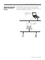
The examples in this manual are based on a system consisting of a
host platform connected to the DeviceNet network via the 1784-PCIDS
card, a series 9000 photoeye, and a RediSTATION. When you have
finished installing all of your devices, your system should appear
similar to that shown below.
Host PC with 1784-PCIDS card,
running IOLinx, RSLinx, and
RSNetWorx for DeviceNet
Node 0
∗
∗
Node 9
DeviceNet Network
Series 9000
Photoelectric
Sensor
Node 7
RediSTATION
Operator Interface
∗ See note blow below.
IMPORTANT
What’s Next?
Make sure each end of your DeviceNet trunk cable
is properly terminated with a resistor. Refer to the
DeviceNet Cable Planning and Installation Manual,
publication DN-6.7.2 for detailed information.
The next step is to configure the 1784-PCIDS card and perform I/O
data mapping using RSNetWorx for DeviceNet software.
Publication 1784-6.5.30 - February 2001
3-8
Setting Up the Hardware for the Example Network
Publication 1784-6.5.30 - February 2001
Chapter
4
Configuring the DeviceNet Network
What This Chapter Contains
This chapter describes how to configure the DeviceNet network using
RSLinx and RSNetWorx for DeviceNet software. The following table
describes where to find specific information. Note that if you need
further information, detailed tutorials are provided with the software.
For information about
Required Software
See page
Required Software
4-1
Installing the Software
4-2
Configuring the RSLinx 1784-PCIDS DeviceNet Driver
4-2
Configuration Screen Map
4-7
Setting Up an Online Connection
4-8
Configuring the I/O Devices
4-10
Verifying the Photoeye Configuration
4-14
Verifying the RediSTATION Configuration
4-15
AutoMapping the Devices into the Scanlist
4-16
Downloading the Configuration to the Scanner
4-19
The example network described in this manual requires the following
Rockwell software. You must install RSLinx before installing the other
two software packages.
1. RSLinx (must be installed first)
2. IOLinx (shipped with the 1784-PCIDS scanner card)
3. RSNetWorx for DeviceNet (to configure the network)
1
Publication 1784-6.5.30 - February 2001
4-2
Configuring the DeviceNet Network
Installing the Software
IMPORTANT
We strongly recommend that you exit all Windows
programs before running the Setup programs.
To install Rockwell software products from a CD, use the following
procedure:
1. Insert the setup CD in the CD-ROM drive.
Note: The setup CD-ROMs support Windows Autorun. Once
inserted into the CD-ROM drive, the installation will automatically
start at the first setup screen if you have Autorun enabled.
If Autorun is enabled for your CD-ROM drive, go to step 5.
2. From the Start menu, choose Run.
You will see the Run pop-up window.
3. Type d:\setup (if it doesn’t appear automatically), where d: is
your CD-ROM driver letter.
4. Click on OK.
You will see the progress bar, followed by the welcome screen.
5. Follow the prompts on the screen as you set up your software.
Configuring the RSLinx
1784-PCIDS DeviceNet
Driver
RSNetWorx for DeviceNet uses the RSLinx 1784-PCIDS driver to
communicate with the devices on the DeviceNet network. In order to
use this driver you must first:
1. Install the driver from the runtime IOLinx CD-ROM supplied
with the card.
2. Configure the DeviceNet port and driver in RSLinx.
IMPORTANT
Publication 1784-6.5.30 - February 2001
You must install the PCIDS driver from the runtime
IOLinx CD-ROM supplied with the card before you
can configure the port and driver.
Configuring the DeviceNet Network
4-3
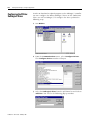
Use the following procedure to configure the RSLinx 1784-PCIDS
driver for use with RSNetWorx for DeviceNet:
1. Start RSLinx.
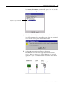
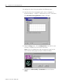
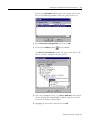
2. From the Communications menu, select Configure Drivers.
The Configure Drivers window will open.
3. From the list of Available Driver Types, select DeviceNet
Drivers and click on Add/New. You will see the DeviceNet
Driver Selection window with the drivers available on your
machine.
Publication 1784-6.5.30 - February 2001
4-4
Configuring the DeviceNet Network
Note: If the 1784-PCIDS driver does not appear in your list, the
PCIDS driver did not install properly from the IOLinx CD-ROM.
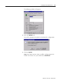
4. Highlight the Allen-Bradley 1784-PCIDS driver and click on
Select.
The 1784-PCIDS Driver Configuration window will open.
Note: If you have multiple PCIDS cards installed for your
application, use the Serial Number pulldown window to select
the PCIDS you want to configure. Check the PCI Slot number to
make sure you have selected the right card.
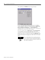
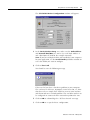
5. Click on Test Card.
Publication 1784-6.5.30 - February 2001
Configuring the DeviceNet Network
4-5
You should receive the following message.
If the tests fail you have a hardware problem in your computer.
The card may be defective, improperly seated in its slot, etc. Note
that these are simply basic hardware tests on your machine and do
not indicate a network problem. (The card does not have to be
configured or connected to the network to perform the tests.)
6. Click on OK.
IMPORTANT
Your DeviceNet network must be connected and
powered up before continuing.
7. In the DeviceNet Port Setup area of the Driver Configuration
window, make sure the Node Address and Network Baud Rate
are correct (we used Node Address 0 and a Baud Rate of 500K for
the example network).
8. Click on OK. You will be prompted to choose a name for the new
RSLinx driver.
9. Accept the default name (1784-PCIDS-1) and click on OK.
Publication 1784-6.5.30 - February 2001
4-6
Configuring the DeviceNet Network
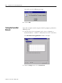
The new driver will be added to the list of configured RSLinx
drivers. (Your screen will display the drivers you have configured
on your system.)
The driver’s Status should be “Running”. If not, there is
a problem. Check the physical connection to the PCIDS
card. If the physical connection is intact, verify the
network baud rate and ensure that the PCIDS card’s
node number is unique. Also check the external 24V
power connections. The Network LED on the
1784-PCIDS card should be solid or flashing green.
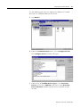
10. From the Communications menu select RSWho. Expand the
tree under the 1784-PCIDS driver and make sure that you see all
of the devices on the network.
Workstation, US008073485
Linx Gateways, Ethernet
1784-PCIDS, DeviceNet
07, 2705T
09, Series 9000(Strobe)Diffuse w/cable
00, Workstation, US00807385
.
TIP
11. Close RSLinx.
Publication 1784-6.5.30 - February 2001
If RSLinx fails to find a device, check the physical
connection to the device. If the physical connection
is intact, verify the device’s baud rate and ensure that
its node number is unique. Also check the external
power connections to the device. The Network LED
on the 1784-PCIDS card should be solid or flashing
green.
Configuring the DeviceNet Network
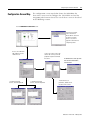
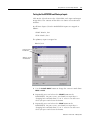
Configuration Screen Map
4-7
The configuration screen map below shows the RSNetWorx for
DeviceNet screens used to configure the 1784-PCIDS card and the
navigation paths between them. The use of these screens is described
in the following sections.
The main RSNetWorx for DeviceNet screen.
To browse the network,
click on the Online or
Browse buttons and select
the driver. If no PCIDS
driver is seen, refer to
page 4-2 for information on
configuring a driver.
To access the 1784-PCIDS
card, double-click on the
1784-PCIDS icon.
To manually map input
devices, select the Input tab .
To access the scanlist, click on the
Scanlist tab. If online you will be
prompted to upload or download
the scanlist.
To manually map output
devices, select the Output tab.
To download the scanlist, go online
and click on the Download to
Scanner button.
To edit a device’s I/O
parameters, double-click on
the device in the scanlist.
Publication 1784-6.5.30 - February 2001
4-8
Configuring the DeviceNet Network
Setting Up an Online
Connection
Follow the procedure below to set up an online connection to the
DeviceNet network using the 1784-PCIDS driver.
1. Start RSNetWorx for DeviceNet.
2. From the File menu, select New.
If you have RSNetWorx for ControlNet installed on your computer
you may see the following window. Otherwise, proceed to step 4.
3. Highlight DeviceNet Configuration and click on OK.
4. Click on the Online button
Publication 1784-6.5.30 - February 2001
on the toolbar.
Configuring the DeviceNet Network
4-9
The Browse for network window will appear. You will see the
drivers you have configured on your system.
If you do not see the 1784-PCIDS
driver, refer to page 4-2.
5. Select the 1784-PCIDS, DeviceNet driver and click on OK.
You will be prompted that you will have to upload or download
devices before viewing their online configuration.
6. Click on OK to go online and browse the network.
RSNetWorx for DeviceNet will begin browsing for network
devices. When the software is finished browsing, the network
displayed on your screen should look similar to the one shown
below.
Publication 1784-6.5.30 - February 2001
4-10
Configuring the DeviceNet Network
TIP
By default, RSNetWorx for DeviceNet performs a
one-shot browse when you go online or choose the
browse feature. The software will poll for devices
once and display the results. Consequently, there
will be no “live” indication if a node which was
online later goes offline or if a new node comes
online.
• Check the Autobrowse box if you want the
software to browse and update continuously.
• You can also manually perform a browse at any
time by pressing the browse button
Configuring the I/O Devices
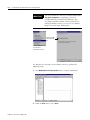
Next you must add the RediSTATION and the photoeye to the
1784-PCIDS scanlist, configure and/or verify their parameters, and
map the devices to the scanner’s memory.
IMPORTANT
Always do an upload of the entire network to
preserve existing configurations before configuring
new devices or reconfiguring existing devices.
1. Double-click on the 1784-PCIDS module icon.
Publication 1784-6.5.30 - February 2001
.
Configuring the DeviceNet Network
4-11
The following window will appear:
2. Select the Module tab.
You will be prompted to upload or download the configuration.
3. Click on Upload.
Note: You could also have done an offline configuration of the
PCIDS card. In that case, you would select Download.
Publication 1784-6.5.30 - February 2001
4-12
Configuring the DeviceNet Network
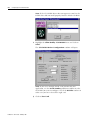
After uploading the Module property page will open:
On the 1784-PCIDS Module property page you can configure
scanner parameters online. The module parameters (Interscan
Delay, Poll Ratio, Packet Rate, and Transmit Retries)
determine how the 1784-PCIDS DeviceNet scanner communicates
with other devices on the DeviceNet network.
The factory defaults for the Packet Rate and Transmit Retries
are the optimum values for most applications. Since these
parameters are not used frequently, they do not appear on this
property page. You access them by clicking the Advanced button.
We do not recommend changing these unless there is a need to
do so.
TIP
Publication 1784-6.5.30 - February 2001
For an explanation of each module parameter,
use the context-sensitive help on this property
page, and on the Advanced Module Settings and
Slave Mode dialog boxes.
Configuring the DeviceNet Network
4-13
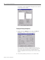
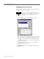
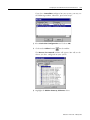
4. Select the Scanlist tab.
The Scanlist page will appear with the RediSTATION and the
photoeye in the list of Available Devices.
TIP
If the devices do not appear, go back and
browse the network again to make sure they are
present.
RediSTATION and photoeye
should appear in the list of
Available Devices.
5. For this example, uncheck the Automap on Add box, as shown
above. We will do this mapping later.
6. Click on the double arrow
RediSTATION to the Scanlist.
button to add the photoeye and
Publication 1784-6.5.30 - February 2001
4-14
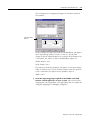
Configuring the DeviceNet Network
The photoeye and the RediSTATION will appear in the Scanlist in
the right panel of the window.
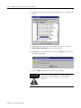
Verifying the Photoeye Configuration
1. Double-click on the photoeye in the Scanlist. The Edit I/O
Parameters window will appear for the photoeye.
The I/O parameters define the configuration for the device in
terms of how much and with what data transmission format the
device will exchange data with the 1784-PCIDS module. By
default, the photoeye will send 1 byte when it receives a strobe
request.
2. Verify that the photoeye parameters are set as shown above.
Publication 1784-6.5.30 - February 2001
Configuring the DeviceNet Network
4-15
3. Click on OK if you made any changes and close the photoeye
Edit I/O Parameters window.
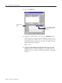
Verifying the RediSTATION Configuration
1. Double-click on the RediSTATION in the Scanlist window. The
Edit I/O Parameters window will appear for the RediSTATION.
2. Make sure that the Polled box is checked and that the Rx Size
and Tx Size are each 1 byte.
3. Click on OK if you made any changes and close the Edit I/O
Parameters window for the RediSTATION.
Publication 1784-6.5.30 - February 2001
4-16
Configuring the DeviceNet Network
AutoMapping the Devices into the Scanlist
Follow the procedure below to automatically map the photoeye and
RediSTATION to the personal computer.
TIP
If you want to know how to map the devices
manually, click on the Help button at the bottom of
the screen and select “Map device input data
manually.”
1. Select the Input tab. You will see the following window.
Input data is read from input image tables. Mapping to and from
these tables is done as a word index, offset from zero. There is no
reserved status or command bytes in the mapped image tables.
The Options button provides you the option of aligning the data
on byte or word boundaries.
This Advanced button allows you to specify the mapping
parameters manually if so desired.
2. Highlight the RediSTATION and the photoeye and click on the
AutoMap button.
Publication 1784-6.5.30 - February 2001
Configuring the DeviceNet Network
4-17
The resulting device mapping will appear in the lower panel of
the window:
Input Image Table,
Word 0
Photoeye
inputs
RediSTATION
inputs
In this example, the input byte from the RediSTATION will appear
in the Input Image Table in word 0, as bits 0-7. Recall from
chapter 2 that the START button is bit 1 and the STOP button is bit
0. Therefore, the addresses for the RediSTATION inputs are:
START: Word 0, bit 1
STOP: Word 0, bit 0
The input byte from the photoeye will appear in the Input Image
Table as word 0, bits 8-15. Recall from chapter 2 that the input bit
is bit 0. Therefore, the address of the photoeye input is:
Word 0, bit 8
3. Note the input mapping assigned to the START and STOP
buttons and the photoeye in your system. You will need this
mapping for your application. (See Appendix B for an example of
using this mapping in a SoftLogix 5 program.)
Publication 1784-6.5.30 - February 2001
4-18
Configuring the DeviceNet Network
4. Select the Output tab.
Output Image File,
Word 0
After Automapping, the output
byte of the RediSTATION will
appear here.
5. Highlight the RediSTATION and click on the AutoMap button.
In this example, the output to the RediSTATION appears in the
Output Image File as Word 0, bits 0-7. Recall from chapter 2 that
the indicator light is output bit 0. Therefore, the address for the
RediSTATION’s indicator light is:
Word 0, bit 0
6. Note the output mapping assigned to this output in your
system. You will need this mapping for your application. (See
Appendix B for an example of using this mapping in a SoftLogix 5
program.)
Publication 1784-6.5.30 - February 2001
Configuring the DeviceNet Network
4-19
Downloading the Configuration to the Scanner
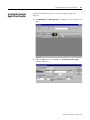
1. Click on the Scanlist tab and then on the Download to Scanner
button.
You will see this window:
2. Select All Records and click on the Download button to
download the configuration to the 1784-PCIDS scanner card.
IMPORTANT
Your application must not be running when
downloading to the scanner card.
3. Click on the OK button to complete the DeviceNet scanner
configuration.
Note: The Network Status LED on the photoeye will turn solid
green to indicate that the photoeye has been configured.
4. Close the Scanlist window.
5. Select the Save as option from the RSNetWorx for DeviceNet File
menu, and save the DeviceNet configuration, using an appropriate
name, e.g., 1784-PCIDS.dnt.
6. Close or minimize RSNetWorx for DeviceNet.
What’s Next?
The next chapter describes how to test the DeviceNet network using
the IOLinx runtime software supplied with the card.
Publication 1784-6.5.30 - February 2001
4-20
Configuring the DeviceNet Network
Publication 1784-6.5.30 - February 2001
Chapter
5
Using IOLinx To Test the Example Network
What This Chapter Contains
This chapter describes how to use the IOLinx runtime software
supplied with the 1784-PCIDS card to test the example DeviceNet
network. The following table describes where to find specific
information.
For information about
Using IOLinx to Configure
the 1784-PCIDS Port
5-1
Testing the DeviceNet Network
5-4
Testing the RediSTATION and Photoeye Inputs
5-7
Testing the RediSTATION Output
5-8
Using the IOLinx Device Status Screen
5-6
Included with the IOLinx for 1784-PCIDS driver is a stand alone test
application (DNetTest.exe) that can be used to diagnose simple
problems over the network. The test application is automatically
installed as part of the driver installation procedure. You can also use
this test application to configure the DeviceNet port on the
1784-PCIDS card, instead of using RSLinx as described in chapter 4.
The procedures are almost identical.
TIP
1
See page
Using IOLinx to Configure the 1784-PCIDS Port
The port configuration is stored in the Windows
system registry. If you have already created a port
for the card (e.g., using RSLinx), you can skip this
section and proceed to Testing the DeviceNet
Network on page 5-4.
Publication 1784-6.5.30 - February 2001
5-2
Using IOLinx To Test the Example Network
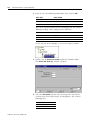
To configure the DeviceNet port perform the following steps:
1. Start the DeviceNet test program (path = Start → Programs →
Rockwell Software → IOLinx → IOLinx for DeviceNet → DNetTest.
The DeviceNet Test Application window will open.
2. From the Setup menu, select Configure Port. You will see your
machine’s available DeviceNet Driver Selections.
Note: If the 1784-PCIDS driver does not appear in your list, the
driver did not install properly from the IOLinx CD-ROM.
3. Highlight the Allen-Bradley 1784-PCIDS driver and click on
Select.
Publication 1784-6.5.30 - February 2001
Using IOLinx To Test the Example Network
5-3
The 1784-PCIDS Driver Configuration window will appear.
4. In the DeviceNet Port Setup area, make sure the Node Address
and Network Baud Rate are correct (we used Node Address 0
and a Baud Rate of 500K for the example network).
Note: If you have multiple PCIDS cards installed in your computer
for your application, use the Serial Number pulldown window to
select the PCIDS you want to configure.
5. Click on Test Card.
You should receive the following message.
If the tests fail you have a hardware problem in your computer.
The card may be defective, improperly seated in its slot, etc. Note
that these tests are simply basic hardware tests on your machine
and do not indicate a network problem. The card does not have to
be configured or connected to the network to perform the tests.
6. Click on OK to acknowledge the “All Tests Passed!” message.
7. Click on OK to accept the driver configuration.
Publication 1784-6.5.30 - February 2001
5-4
Using IOLinx To Test the Example Network
You will receive the following message.
8. Click on OK.
Testing the DeviceNet
Network
To test the example network using the DNetTest program, perform the
following steps:
1. Start the DeviceNet test program (path = Start → Programs →
Rockwell Software → IOLinx → IOLinx for DeviceNet → DNetTest.
The DeviceNet Test Application window will open.
2. From the Setup menu select Create View.
Publication 1784-6.5.30 - February 2001
Using IOLinx To Test the Example Network
5-5
The View Creation Parameters window will open.
3. In the Port Names field, select your 1784-PCIDS card’s port (e.g.,
“DeviceNet Port A”).
Note: You must use the down arrow on your keyboard to scroll
through the list of Port Names.
4. Under the Message Type select Input & Output.
5. Under Privileges select Read/Write.
6. Click on OK.
You will see the following message.
7. Click on OK.
Publication 1784-6.5.30 - February 2001
5-6
Using IOLinx To Test the Example Network
Using the IOLinx Device Status Screen
The Device Status screen displays an Idle/Failure Table where you
can double-click on a node to see its status, including MAC ID, status
code, and status info (e.g., device stopped communicating).
Make sure that there are no failures (“F”) indicated for the devices on
your network (e.g., the 1784-PCIDS card at node 0, the RediSTATION
at node 7, and the photoeye at node 9). If you do see an “F”,
double-click on it to read the error message.
Note: If you double-click on an empty node, you see the response
“OK or not in scan list.”
Publication 1784-6.5.30 - February 2001
Using IOLinx To Test the Example Network
5-7
Testing the RediSTATION and Photoeye Inputs
Click on the I/O tab to view the 1784-PCIDS card’s input and output
image tables. The contents of the tables are shown as hexadecimal
numbers.
Recall from chapter 5 that the RediSTATION inputs are mapped as
follows:
START: Word 0, bit 1
STOP: Word 0, bit 0
The photoeye input is mapped to:
Word 0, bit 8
One byte shown in
hexadecimal
Addresses are also
in hexadecimal
1. Use the Switch Mode button to change the scanner’s mode from
IDLE to RUN.
2. Repeatedly press and release the START button on the
RediSTATION. On your screen, you should see input byte 0
changing back and forth from “0” to “2” as bit 1 sets and resets
when you press and release the button.
3. Repeatedly press and release the STOP button on the
RediSTATION. On your screen, you should see input byte 0
changing back and forth from “0” to “1” as bit 0 sets and resets
when you press and release the button.
Publication 1784-6.5.30 - February 2001
5-8
Using IOLinx To Test the Example Network
4. Pass your hand back and forth over the photoeye several times.
On your screen you should see input byte 1 toggling back and
forth between “0” and “1” as the photoeye input turns on and off.
Testing the RediSTATION Output
Recall from Chapter 5 that the RediSTATION’s indicator light is
mapped to Output Word 0, bit 0.
1. If the scanner is not in RUN mode, use the Switch Mode button
to change the scanner’s mode from IDLE to RUN.
2. Select byte 0 from the Output table, type in a “1” in the New
Value field and click on the Write button. The red indicator light
on the RediSTATION should turn on.
3. Select byte 0 from the Output table, type in a “0” in the New
Value field and click on the Write button. The red indicator light
on the RediSTATION should turn off.
Publication 1784-6.5.30 - February 2001
Using IOLinx To Test the Example Network
WARNING
!
5-9
If you perform a Write test to a device on your
network be certain that you are writing to the correct
location and that you are aware of the possible
results of writing to that device. Failure to observe
these precautions could result in unexpected
machine motion, property damage, or injury to
personnel.
This completes the IOLinx test of your network.
Publication 1784-6.5.30 - February 2001
5-10
Using IOLinx To Test the Example Network
Publication 1784-6.5.30 - February 2001
Appendix
A
Diagnostics and Troubleshooting
What This Appendix
Contains
The 1784-PCIDS communication interface card has three LED
diagnostic indicators. The diagnostics provided by these indicators are
described in this appendix.
For information about the
I/O Status Indicator
Module (MOD) Status Indicator
Network (NET) Status Indicator
I/O Status Indicator
See page
A-1
A-2
A-2
The bicolor (green/red) I/O Status LED provides information
concerning the states of inputs and/or outputs.
I/O Status Indicator
Condition
Status
off
output(s) inactive
input(s) inactive
• All outputs are inactive.
• All inputs are inactive.
green
output(s) active
input(s) active
• One or more outputs are active and
under control, and no outputs are
“faulted.”
• One or more inputs are active and
producing data, and no inputs are
“faulted.”
flashing green(1) output(s) idle
flashing red(1)
1
• One or more outputs are idle and no
outputs are active or “faulted.”
• One or more outputs are “faulted,”
and may be in the fault state.
• One or more inputs are “faulted,”
and may be in the fault state.
• One or more outputs are forced off
(may be an unrecoverable fault).
• One or more inputs has an
unrecoverable fault.
The flash rate of the LED is approximately 1 flash per second. The LED should be on for
approximately 0.5 seconds and off for approximately 0.5 seconds.
red
(1)
output(s) faulted
input(s) faulted
Indicates
output(s) forced off
input unrecoverable
fault
Publication 1784-6.5.30 - February 2001
A-2
Diagnostics and Troubleshooting
Module (MOD)
Status Indicator
This bi-color (green/red) LED indicates whether or not the
1784-PCIDS card has power and is operating properly.
Network Status Indicator
condition
status
indicates
off
no power
No power applied to device
green
device operational
Device is operating in a normal condition.
flashing green(1) device in standby
(device needs
commissioning)
Device needs commissioning due to
configuration missing, incomplete, or
incorrect.
Device may be in the standby state. Refer to
the DeviceNet Specification, Volume II,
Identity Object.
flashing red(1)
recoverable fault
e.g., the device’s scan list configuration does
not match the actual network configuration.
red
unrecoverable fault
Device has an unrecoverable fault. Cycle
power to the card by shutting down and
cycling power to your computer. If the problem
persists the device may need to be replaced.
flashing
device self testing
Device is in self test. Refer to the DeviceNet
red-green
Specification, Volume II, Identity Object.
(1)
The flash rate of the LED is approximately 1 flash per second. The LED should be on for
approximately 0.5 seconds and off for approximately 0.5 seconds.
Network (NET)
Status Indicator
This bi-color (green/red) LED indicates the status of the
communication link
Network Status Indicator
condition
status
indicates
off
not powered,
not online
Device is not online.
• The device has not completed the
Dup_MAC_ID test yet.
• The device may not be powered; look at
the Module Status LED.
flashing green(1) online,
not connected
The device has passed the Dup_MAC_ID test
and is online, but has no established
connections to other nodes.
green
link okay, online,
connected
The device is online and has connections in
the established state.
flashing red(1)
connection time-out
One or more I/O connections are in the
timed-out state.
red
critical link failure
(1)
Publication 1784-6.5.30 - February 2001
Failed communication device. The device has
detected an error that has rendered it
incapable of communicating on the network
(Duplicate MAC ID or Bus-off).
Check network integrity and baud rate of all
devices. Then cycle power to the card by
shutting down and cycling power to your
computer.
The flash rate of the LED is approximately 1 flash per second. The LED should be on for
approximately 0.5 seconds and off for approximately 0.5 seconds.
Appendix
B
Creating and Running
a SoftLogix 5 Application
What This Appendix
Contains
IMPORTANT
Make sure you have completed the installation and
configuration of the example DeviceNet network
described earlier in this manual before creating this
SoftLogix 5 application.
This appendix describes the procedure to create, download, and run a
SoftLogix 5 ladder program to test the DeviceNet network described
in this manual. When the program is put into Run mode, pressing the
START button on the network’s RediSTATION will cause the red
indicator light to come on and stay on until the STOP button is
pressed. Passing an object in front of the photoeye will increment a
counter.
We use RSLogix 5 programming software to create and download the
ladder program. For this example, we assume that RSLogix 5 is
running on the same computer as the SoftLogix 5 controller engine. It
is also possible to run RSLogix 5 on a workstation or programming
terminal communicating with the SoftLogix controller over an Ethernet
or Data Highway Plus network.
IMPORTANT
You must have administrative or programmer rights
in SoftLogix 5 in order to create and run the example
application. Check with your system administrator.
The following table describes what this appendix contains and where
to find specific information.
For information about
1
See page
Configuring the RSLinx SoftLogix 5 Driver
B-2
Configuring the SoftLogix 5 DeviceNet Driver
B-4
Putting the SoftLogix Controller in Remote Mode
B-6
Creating the Example Application Program
B-7
Downloading the Program
B-10
Running the Example Program
B-11
Publication 1784-6.5.30 - February 2001
B-2
Creating and Running a SoftLogix 5 Application
Configuring the RSLinx
SoftLogix 5 Driver
In order to download or upload programs to the SoftLogix 5 controller
you must configure the RSLinx SoftLogix 5 driver on the workstation
where you will run RSLogix 5. To configure the driver perform the
following steps:
1. Start RSLinx.
2. From the Communications menu, select Configure Drivers.
The Configure Drivers window will open.
3. Select the SoftLogix 5 driver from the pull-down list and click on
Add/New. You will see the following pop-up window.
Publication 1784-6.5.30 - February 2001
Creating and Running a SoftLogix 5 Application
B-3
4. Select the default name assigned by the system (e.g., SOFT5-1)
and click on OK.
The Configure driver window will open.
5. Enter the Host Name of your host platform (e.g., US00807385) and
click on OK.
Your SoftLogix 5 driver will be added to the list of Configured
Drivers (Your list will show the drivers you have configured on
your system).
6. Close the Configure Drivers window and exit RSLinx.
Publication 1784-6.5.30 - February 2001
B-4
Creating and Running a SoftLogix 5 Application
Configuring the SoftLogix 5
DeviceNet Driver
In order for the SoftLogix 5 controller to communicate with the
DeviceNet network, you must configure the SoftLogix 5 DeviceNet
driver.
To configure the SoftLogix 5 DeviceNet driver, perform the following
steps:
1. Click on the SoftLogix 5 Status Monitor in the System tray at the
bottom of your screen.
The SoftLogix 5 Status Monitor window will open.
2. Click on the Config button.
Publication 1784-6.5.30 - February 2001
Creating and Running a SoftLogix 5 Application
B-5
3. Select the I/O Device Driver Configuration tab.
4. Highlight the A-B DeviceNet Scanner and click on Install.
The PCIDS Port Configuration window will open.
5. Accept the default settings and click on OK.
Publication 1784-6.5.30 - February 2001
B-6
Creating and Running a SoftLogix 5 Application
The A-B DeviceNet Scanner will be added to the Installed
Drivers.
6. Click on Apply and Close the window.
Putting the SoftLogix
Controller in Remote Mode
In order to download the example application program described in
the following section, the SoftLogix Controller should be placed in
Remote mode.
Remote
Click on the Remote button on the SoftLogix 5 Status Monitor
window. Then click on OK.
Publication 1784-6.5.30 - February 2001
Creating and Running a SoftLogix 5 Application
Creating the Example
Application Program
B-7
Perform the following steps to create the example application
program.
1. Start RSLogix 5 or RSLogix SL5. The RSLogix 5 main window will
open.
2. From the File menu select New. The Select Processor Type
window will open.
Publication 1784-6.5.30 - February 2001
B-8
Creating and Running a SoftLogix 5 Application
3. Enter or select the following information. Then click on OK.
In this field
Select or Enter
Processor Name
Platform
(enter a name of your choice)
Soft Controller
Processor
SoftLogix 5 (entered by system)
You can accept the defaults for the remaining fields. We used the
following settings. (Your settings may be different.)
Series
Revision
C
A
Driver
Processor Node
SOFT5-1
1
On the left side of the RSLogix 5 screen is the Project window:
4. Double-click on Processor Status under the Controller folder.
The Status File (File S2) window will open.
5. Select the DeviceNet tab and enter the integer files that will be
used for DeviceNet Output, Input, and Diagnostics. We used the
following files:
Publication 1784-6.5.30 - February 2001
Output File S:509
20
Input File S:510
Diagnostic File S:511
21
22
Creating and Running a SoftLogix 5 Application
B-9
In this example, Status file word 509 points to integer file 20 (N20)
as the DeviceNet output file, Status file word 510 points to integer
file 21 (N21) as the DeviceNet input file, and Status file word 511
points to integer file 22 (N22) as the DeviceNet diagnostic file.
Word 0 of file N20 now corresponds to word 0 of the 1784-PCIDS
scanner’s output image file. Word 0 of file N21 corresponds to the
word 0 of the 1784-PCIDS scanner’s input image file, etc.
6. Close the Status file window.
The DeviceNet files will be added to the Data Files folder.
7. Enter the following ladder program:
RediSTATION Start bit
RediSTATION
Indicator Light bit
RediSTATION Stop bit
Photoeye input bit
8. Save the program using an appropriate name, e.g., “DNET_SL5”.
Publication 1784-6.5.30 - February 2001
B-10
Creating and Running a SoftLogix 5 Application
Downloading the Program
Follow the procedure below to download the example program to
your SoftLogix 5 controller.
1. Click on the Comms menu and select System Communications.
The RSLinx Communications window will open (your window
will appear different from that shown below, depending upon the
system you have set up).
2. Select the SOFT5-1, Ethernet driver. Expand the tree under driver
and highlight your own SoftLogix controller as shown in the figure
above.
3. Click on the Download button.
You will be prompted to proceed with the Download. You will
see a message similar to the one shown below.
4. Click on Yes to download the program to the SoftLogix controller.
Publication 1784-6.5.30 - February 2001
Creating and Running a SoftLogix 5 Application
Running the Example
Program
B-11
Perform the following steps to run the program and test your network.
1. After the download is complete, go online and put the SoftLogix
controller into Run mode.
2. Press and release the START button on the RediSTATION. The red
light should turn on. On your screen, you should see rung 0 in
your ladder program become energized as you press the button.
3. Pass your hand back and forth over the photoeye several times.
On your screen you should see the counter incrementing.
4. Press and release the STOP button on the RediSTATION. The red
light should turn off. On your screen, you should see rung 2 in
your ladder program being energized as you press the button.
This completes the SoftLogix 5 example application.
Publication 1784-6.5.30 - February 2001
B-12
Creating and Running a SoftLogix 5 Application
Publication 1784-6.5.30 - February 2001
Appendix
C
Configuring the DeviceNet Network
from Another Network
What This Appendix
Contains
This appendix describes how to access the 1784-PCIDS card from a
remote workstation on another network and configure the DeviceNet
network. Examples are provided for accessing the 1784-PCIDS card
via a ControlLogix Gateway from an Ethernet or Data Highway Plus
network, and for accessing the 1784-PCIDS card via an RSLinx
Gateway.
You must have previously set up the RSLinx Gateway or ControlLogix
Gateway you will use to communicate with the 1784-PCIDS card. For
more information on using a ControlLogix Gateway, see the
ControlLogix Gateway System User Manual, publication 1756-6.5.13.
For information on RSLinx Gateways, refer to the RSLinx software
Help screens.
ATTENTION
!
Remote access should be used only for configuration
of your network devices. The remote access method
is not suitable for real time monitoring of your
network devices.
The following table describes what this appendix contains and where
to find specific information.
For information about
1
See page
Configuring the DeviceNet Network Via a ControlLogix Gateway
C-2
Configuring the DeviceNet Network Via an RSLinx Gateway
C-5
Publication 1784-6.5.30 - February 2001
C-2
Configuring the DeviceNet Network from Another Network
Configuring the DeviceNet
Network Via a ControlLogix
Gateway
In order to access the 1784-PCIDS card via a ControlLogix Gateway
your system must be set up as shown below. The ControlLogix chassis
must contain a 1756-DNB module connected to the DeviceNet
network, as well as a communications module for the network on
which the remote workstation resides (i.e., a 1756-CNB, 1756-DHRIO,
or 1756-ENET module).
Host Platform with
1784-PCIDS card
ControlLogix Gateway
1756-DHRIO, or
1756-ENET
Workstation with
RSNetWorx for
DeviceNet
1756-DNB
DeviceNet Network
Ethernet, or DH+ Network
To configure the network via a ControlLogix Gateway perform the
steps below:
1. Start RSNetWorx for DeviceNet on your remote workstation.
2. From the File menu, select New.
Publication 1784-6.5.30 - February 2001
Configuring the DeviceNet Network from Another Network
C-3
If you have ControlNet configured on your remote system, you
may see the following window. Otherwise, proceed to step 4.
3. Select DeviceNet Configuration and click on OK.
4. Click on the Online button
on the toolbar.
The Browse for network window will appear. You will see the
drivers you have configured on your system.
5. Select the appropriate driver (e.g. TCP-1, Ethernet) and expand
the tree through the ControlLogix backplane until you reach the
DeviceNet network as shown above.
6. Highlight the DeviceNet icon and click on OK.
Publication 1784-6.5.30 - February 2001
C-4
Configuring the DeviceNet Network from Another Network
You will receive the following prompt:
7. Click on OK to go online and browse the network.
ATTENTION
!
Performing a remote browse may take longer than
browsing using the 1784-PCIDS driver as described
in chapter 4.
When the software is finished browsing, the DeviceNet network
will be displayed on your workstation’s screen, similar to the
example network shown below.
Once you are online to the DeviceNet network you can perform
the procedures described on pages 4-8 to 4-19 of this manual to
configure the DeviceNet network.
Publication 1784-6.5.30 - February 2001
Configuring the DeviceNet Network from Another Network
Configuring the DeviceNet
Network Via an RSLinx
Gateway
C-5
With this method the remote workstation and the host computer
containing the 1784-PCIDS card are connected to the Ethernet
network. The host computer is configured as an RSLinx Gateway and
the remote workstation is a gateway client.
Gateway Client running
RSLinx and RSNetWorx for
DeviceNet
Ethernet Network
Host Computer
(RSLinx Gateway
Server)
1784-PCIDS
DeviceNet Network
Publication 1784-6.5.30 - February 2001
C-6
Configuring the DeviceNet Network from Another Network
IMPORTANT
You must install the Gateway version of RSLinx on
the host computer by obtaining a Gateway
authorization key from Rockwell Software and
checking the Enable RSLinx Gateway box on the
Configure RSLinx Gateway screen. See the RSLinx
Help screens for more information.
Check the Enable
RSLinx Gateway
box.
Select Configure Gateway
from the RSLinx
Communications menu
To configure the network via the RSLinx Gateway, perform the
following steps:
1. Start RSNetWorx for DeviceNet on the remote workstation.
2. From the File menu, select New.
Publication 1784-6.5.30 - February 2001
Configuring the DeviceNet Network from Another Network
C-7
If you have ControlNet configured on your system, you may see
the following window. Otherwise, proceed to step 4.
3. Select DeviceNet Configuration and click on OK.
4. Click on the Online button
on the toolbar.
The Browse for network window will appear. You will see the
drivers you have configured on your system.
5. Highlight the RSLinx Gateway, Ethernet driver.
Publication 1784-6.5.30 - February 2001
C-8
Configuring the DeviceNet Network from Another Network
6. Scroll down until you locate your host platform (e.g., US00807385
below).
7. Expand the tree under your host platform until you reach the
1784-PCIDS, DeviceNet driver as shown above.
8. Highlight the DeviceNet driver and click on OK. You will receive
the following prompt:
9. Click on OK to go online and browse the network.
ATTENTION
!
Publication 1784-6.5.30 - February 2001
Performing a remote browse may take longer than
browsing on the host platform as described in
chapter 4.
Configuring the DeviceNet Network from Another Network
C-9
When the software is finished browsing, the DeviceNet network
will be displayed on your workstation’s screen, similar to the
example network shown below.
You are now online to the DeviceNet network via the RSLinx
Gateway.
Refer to the procedures described on pages 4-8 to 4-19 of this manual
for information on how to configure the DeviceNet network.
Publication 1784-6.5.30 - February 2001
C-10
Configuring the DeviceNet Network from Another Network
Publication 1784-6.5.30 - February 2001
Appendix
D
Changing the Network Baud Rate
Required Procedure
This Appendix summarizes what you have to do to change the baud
rate of an existing DeviceNet network. You must perform the steps
below in the following order:
1. Close all applications that might be using the 1784-PCIDS driver.
This includes any Soft Control engines as well as explicit
messaging applications.
2. Delete the 1784-PCIDS driver from RSLinx.
3. Change the baud rate on any non-autobaud devices on your
network by setting the dip switches or individually programming
the devices accordingly.
4. Power down your programming terminal/personal computer and
your 24V network supply.
5. Turn on your 24V network power.
6. Turn on your personal computer.
7. Re-install the 1784-PCIDS driver in RSLinx, using the new baud
rate.
1
Publication 1784-6.5.30 - February 2001
D-2
Changing the Network Baud Rate
Publication 1784-6.5.30 - February 2001
Index
A
about this user manual P-1 to P-7
audience P-1
automapping 4-16 to 4-19
B
before you begin 1-1 to 1-8
C
change of state message 1-5
changing network baud rate D-1
common techniques used in this manual P-3
communicating with your devices 1-5
communicating with your host platform 1-6
configuring DeviceNet from another network C-1 to
example network 2-2 to 2-3, 3-7
system components P-2
H
hardware setup 3-1 to 3-7
PCIDS card 3-1 to 3-4
accessing computer expansion slots 3-2
connecting to the DeviceNet network 3-3
installing the card 3-2 to 3-3
photoeye 3-6
RediSTATION 3-5
help
local product support P-6
Rockwell Automation support P-6
technical product assistance P-6
how your system will look 3-7
C-9
via a ControlLogix gateway C-2 to C-4
via an RSLinx gateway C-5 to C-9
configuring RSLinx PCIDS driver 4-2 to 4-6
configuring the 1784-PCIDS port
using IOLinx 5-1 to 5-4
using RSLinx 4-2 to 4-6
configuring the DeviceNet network 4-1 to 4-19
automapping 4-16 to 4-19
I/O devices 4-10 to 4-19
photoeye 4-14 to 4-19
verifying photoeye configuration 4-14
RediSTATION 4-15 to 4-19
verifying RediSTATION configuration 4-15
scanlist configuration 4-10 to 4-19
setting up an online connection 4-8 to 4-10
using RSNetworx for DeviceNet 4-1 to 4-19
ControlLogix gateway C-2 to C-4
cyclic message 1-5
I
I/O status indicator A-1
input data definition 1-5
input data file 2-5
IOLinx
configuring the 1784-PCIDS port 5-1 to 5-4
create view 5-4 to 5-5
DeviceNet status screen 5-6
input and output image tables 5-7 to 5-9
testing the DeviceNet network 5-4 to 5-9
L
ladder logic program
see SoftLogix 5 example application
M
module (MOD) status indicator A-2
D
data mapping your devices 2-1 to 2-8
photoeye input data mapping 2-7 to 2-8
RediSTATION data mapping 2-4 to 2-6
diagnostics and troubleshooting A-1 to A-2
I/O status indicator A-1
module (MOD) status indicator A-2
network (NET) status indicator A-2
E
N
network (NET) status indicator A-2
network baud rate
changing D-1
O
output data definition 1-5
output data file 2-6
example application P-2, 2-2 to 2-3
Publication 1784-6.5.30 - February 2001
2
Index
P
PCIDS card
installation 3-1 to 3-4
see also hardware setup
photoeye
data mapping 2-7 to 2-8
installation 3-6
scanlist configuration 4-10 to 4-19
testing inputs 5-7 to 5-8
planning your configuration 2-1 to 2-8
beginning the process 2-1
what you need to know 2-1
poll message 1-5
S
scanlist configuration 4-10 to 4-19
scanner data tables 1-7
SoftLogix 5 example application B-1 to B-11
configuring drivers
RSLinx SoftLogix 5 driver B-2 to B-3
SoftLogix 5 DeviceNet driver B-4 to B-6
creating the program B-7 to B-9
downloading the program B-10
running the program B-11
software setup 4-2 to 4-6
configuring RSLinx DeviceNet driver 4-2 to 4-6
installing the software 4-2
required software 4-1
Q
questions or comments about manual P-6
R
RediSTATION
data mapping 2-4 to 2-6
DIP switch setting 3-5
installation 3-5
scanlist configuration 4-15 to 4-19
testing inputs 5-7 to 5-8
testing output 5-8 to 5-9
remote mode
putting controller in remote mode B-6
Rockwell Automation support P-6
RSLinx
configuring PCIDS driver 4-2 to 4-6
SoftLogix 5 driver B-2 to B-3
RSLinx gateway C-5 to C-9
RSNetWorx for DeviceNet
as a configuration tool 1-7
configuring the DeviceNet network 4-1 to 4-19
Publication 1784-6.5.30 - February 2001
T
terminology P-5 to P-6
testing the DeviceNet network 5-4 to 5-9
IOLinx DeviceNet status screen 5-6
RediSTATION and Photoeye inputs 5-7 to 5-8
RediSTATION output 5-8 to 5-9
troubleshooting
see diagnostics and troubleshooting
typical network configuration 1-2
U
using IOLinx to test the example network 5-1 to 5-9
testing the DeviceNet network 5-4 to 5-9
DeviceNet status screen 5-6
RediSTATION and Photoeye inputs 5-7 to 5-8
RediSTATION output 5-8 to 5-9
W
what you need to know 1-1
what your 1784-PCIDS card does 1-2 to 1-4
where to find more information P-4
Allen-Bradley
Publication Problem Report
If you find a problem with our documentation, please complete and return this form.
Pub. Name DeviceNet Communication Interface Card User Manual
Cat. No. 1784-PCIDS, -CPCIDS
Check Problem(s) Type:
Pub. No. 1784-6.5.30
Pub. Date February 2001
Part No. 955134-58
Internal Use Only
Describe Problem(s)
Technical Accuracy
text
Completeness
procedure/step
illustration
definition
info in manual
example
guideline
feature
(accessibility)
explanation
other
What information is missing?
illustration
info not in
Clarity
What is unclear?
Sequence
What is not in the right order?
Other Comments
Use back for more comments.
Your Name
Location/Phone
Return to: Marketing Communications, Allen-Bradley., 1 Allen-Bradley Drive, Mayfield Hts., OH 44124-6118Phone: (440) 646-3176
FAX:
(440) 646-4320
Publication 1784-6.5.30- February 2001
955134-58
(
)
PLEASE FOLD HERE
NO POSTAGE
NECESSARY
IF MAILED
IN THE
UNITED STATES
BUSINESS REPLY MAIL
FIRST-CLASS MAIL PERMIT NO. 18235 CLEVELAND OH
POSTAGE WILL BE PAID BY THE ADDRESSEE
1 ALLEN BRADLEY DR
MAYFIELD HEIGHTS OH 44124-9705
PLEASE REMOVE
Other Comments
Publication 1784-6.5.30 - February 2001 2
Supersedes Publication 1784-6.5.28 - July 1998
PN 955134-58
© 2001 Rockwell International Corporation. Printed in the U.S.A.
DeviceNet PCI Communication Interface Card
User Manual