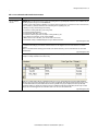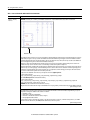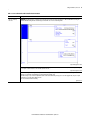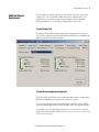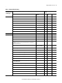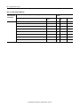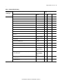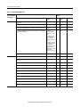
1
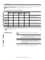
Release Notes
SoftLogix Controllers, Version 20
Catalog Numbers 1789-L10, 1789-L30, 1789-L60
IMPORTANT
Topic
Page
Compatible Software Versions
3
Compatible PCI-based Cards and Drivers
4
System Requirements
4
Before You Begin
6
Corrected Anomalies
8
Enhancements
6
Known Anomalies
12
Restrictions
15
Performing Typed Operations
16
Functionality Issues in Specific Circumstances
17
Install the Controller
19
Use Motion Drivers in Windows XP Systems
20
Use Motion Drivers in Windows XP Systems
20
Additional Memory Requirements
21
Additional Resources
29
Consider the following before upgrading your SoftLogix™ 5800 controller:
• Before updating your controller, we strongly recommend that you review information pertinent to previous major versions. For
example, when updating from version 18.x…20.x, view information for versions 18.15 and 19.11 in these publications:
- SoftLogix 5800 Controllers, Version 18 Release Notes, publication 1789-RN018
- SoftLogix 5800 Controllers, Version 19 Release Notes, publication 1789-RN019
Release notes contain material for all minor versions subsequent to each major version. If your controller, for example, is at version
18.11, and not the latest version, such as 20.x, you should view all of the information for version 18.11…19.11 before updating to
version 20.x.
Release notes are available at http://www.rockwellautomation.com/literature.
• After upgrading your controller, we strongly recommend that you retest and/or validate your application offline before going
online.
2 SoftLogix Controllers, Version 20
About This Publication
This publication describes SoftLogix 5800 controllers, version 20.03.00.
Information that has been added or changed since the last revision of this
publication is indicated by a change bar as shown to the side of this paragraph. In
addition to information specific to the most recent software version, the
information from previous minor versions is retained in these release notes.
We strongly recommend that you review the information provided regarding
previous software versions. We recommend that you do so because, if you are
upgrading your software through multiple previous versions, all of the
information specific to all of the versions is applicable.
For example, if you need to upgrade your 1789-L60 controller from version
19.00.00…20.03.00, all of the information specific to versions
19.00.00…20.03.00 is applicable.
About Publication 1789-RN519C-EN-P
This revision of the SoftLogix Controllers Release Notes, publication
1789-RN519C, provides updated information specific to version 20.03.00.
Table 1 - Controller Versions Identified in Publication 1789-RN519C
Cat. No.
Version
1789-L10
20.03.00
1789-L30
1789-L60
About Publication 1789-RN519B-EN-P
This publication describes SoftLogix 5800 controllers, version 20.01.00.
Table 2 - Controller Versions Identified in Publication 1789-RN519B
Cat. No.
Version
1789-L10
20.01.00
1789-L30
1789-L60
Rockwell Automation Publication 1789-RN519C-EN-P - April 2014
SoftLogix Controllers, Version 20 3
About Publication 1789-RN519A-EN-P
This publication describes SoftLogix 5800 controllers, version 20.00.00.
Table 3 - Controller Versions Identified in Publication 1789-RN519A
Cat. No.
Version
1789-L10
20.00.00
1789-L30
1789-L60
Compatible Software Versions
To use version 20.03.00, these minimum software versions are required.
Table 4 - Compatible Software Versions
Software
Required Software Version, Min
Compare Tool
3.20.02
ControlFLASH™
11.00.00
FactoryTalk® AssetCentre
4.00.00 (CPR 9, SR3)
FactoryTalk Services Platform
2.50.00 (CPR 9, SR5)
FactoryTalk Activation
3.50.00 (CPR 9, SR5)
RSLinx® Classic
2.59.01 (CPR 9, SR5)
RSLinx Enterprise
5.50.04 (CPR 9, SR5)
RSLogix™ 5000
20.03.00 (CPR 9, SR5)
RSNetWorx™ for ControlNet
11.00.00 (CPR 9, SR5)
RSNetWorx for DeviceNet
RSNetWorx for EtherNet/IP
Rockwell Automation Publication 1789-RN519C-EN-P - April 2014
4 SoftLogix Controllers, Version 20
Compatible PCI-based Cards and
Drivers
This table lists PCI-based cards, firmware revisions, and driver versions that you
can use with the SoftLogix controllers, version 20.
Table 5 - Network, Operating System, Firmware, and Driver Compatibility
Network
Operating System
Firmware and Driver Compatibility
Windows XP
Windows 2003 Server Windows Vista
Windows 7
Windows 2008 Server
EtherNet/IP
Yes
Yes
Yes
Yes
NA
All operating systems support Ethernet, whether via a
PCI-based card or other interface.
ControlNet
1784-PCIC/B,
1784-PCICS/B
Yes
Yes
Yes(1)
No
Firmware revision 4.10 and driver revision 4.06(2)
ControlNet
1784-PCIC/A,
1784-PCICS/A
Yes
Yes
Yes(1)
No
Firmware revision 3.10 and driver revision 4.06(2)
DeviceNet
1784-PCIDS/B
Yes
Yes
No
No
Firmware revision 3.016 and driver revision 2.01
DeviceNet
1784-PCIDS/A
Yes
Yes
No
No
Firmware revision 2.008 and driver revision 2.01
(1) Supports ControlNet communication only. These operating systems do not support ControlNet scanner functionality.
(2) If you are installing a ControlNet card for the first time or if you already have a ControlNet card installed, use the instructions in the ControlNet Communication Card Installation Instructions, publication
1784-IN003, to install or update the driver as appropriate.
System Requirements
Table 5 identifies system requirements for the SoftLogix 5800 controller.
IMPORTANT
Use the computer that is running the SoftLogix controller like an industrial controller,
not a personal computer. The SoftLogix controller executes real-time operations. If you
use other programs or applications on the computer when the controller is executing
real-time operations, those operations may be disrupted.
IMPORTANT
SoftLogix controllers and software, version 20 and later, do support EtherNet/IP
networks, but do not support Integrated Motion on EtherNet/IP networks.
Allen-Bradley, PCI-based motion cards are not supported when using the Microsoft
Windows 7 operating system.
For more information, see Knowledgebase document KB 509008.
Rockwell Automation Publication 1789-RN519C-EN-P - April 2014
SoftLogix Controllers, Version 20 5
Table 6 - System Requirements
Category
Description
Personal computer
IBM-compatible Pentium 4 1.6 GHz or later(1)
Other requirements include the following:
• FactoryTalk Activation Manager if you are currently using Factory Activation software.
• A hard disk that supports bus mastering.
• The need for bus-mastering drivers for the personal computer’s chip set; for Intel motherboards, this software is called
Application Accelerator.
• Applications that are resource-intensive, including applications that use sequential, motion, and other local
applications running on the computer, may require a dual CPU to achieve performance requirements.
Operating systems
64-bit
SoftLogix software is supported on 64-bit operating systems.
Supported 64-bit operating systems include the following:
• Microsoft Windows Server 2008 R2 Standard Edition Service Pack 1
• Microsoft Windows 7 Home Premium (64-bit) Service Pack1
• Windows 7 Professional (64-bit) Service Pack 1
IMPORTANT: When SoftLogix software is installed on a 64-bit Windows operating system, the following modules will
be available in the Chassis Monitor:
• SoftLogix controller
• Soft ENBT
• Input/output simulator module
IMPORTANT: Motion, ControlNet, and DeviceNet modules are no longer supported in SoftLogix software on 64-bit
Windows operating systems.
32-bit
SoftLogix software is supported on 32-bit operating systems (x86).
Supported 32-bit operating systems include the following:
• Microsoft Windows XP Professional with Service Pack 3
• Microsoft Windows 7 Home Premium(32-Bit) with Service Pack 1
• Microsoft Windows Vista Business (32-Bit) with Service Pack 2
• Microsoft Windows Server 2008 Standard Edition with Service Pack 2
• Microsoft Windows Server 2003 R2 Standard Edition with Service Pack 2
Accessing SoftLogix software via Remote Desktop on remote machines is not supported.
Virtual Windows operating systems are not supported for executing SoftLogix software.
RAM
1 GB, min
Hard disk space
64 MB of free hard disk space per controller instance (or more based on application requirements)
Network requirements
Primary or extended 32-bit PCI slot (one slot per communication PCI-based card).
Supports 1784-PCICS card for the ControlNet network (not compatible with Microsoft Windows 7 operating system).
Supports 1784-PCIDS card for the DeviceNet network (not compatible with Microsoft Windows Vista, Microsoft Windows
2008 Server, and Microsoft Windows 7 operating systems).
Supports EtherNet/IP and Ethernet port of the personal computer.
Third-party networks are supported through the Rockwell Automation® Encompass™ program.
Video requirements
16-color VGA graphics adapter 640 x 480, or later resolution
(256-color, 800 x 600 min, for optimal resolution)
(1) The SoftLogix 5800 controller has been tested and qualified only on genuine Intel processors.
For system requirements, go to
http://www.rockwellautomation.com/rockwellsoftware/design/rslogix5000/sys
req.html.
Rockwell Automation Publication 1789-RN519C-EN-P - April 2014
6 SoftLogix Controllers, Version 20
Before You Begin
Before you upgrade your controller, consider how close it is to the limits of
memory. This version may require more memory than previous versions.
To see what components of your current project require more memory, see
Additional Memory Requirements on page 21.
IMPORTANT
Rockwell Automation does not assume responsibility or liability (to include intellectual
property liability) for actual use of the external routines featured in a control system
application.
RSLogix 5000 software, version 13.00.00 or later, lets you estimate the memory
requirements of the controller offline.
These enhancements are available when you use controller version 20.00.00 or
later, with RSLogix 5000 software, version 20.00.00 or later.
Enhancements
Table 7 - Enhancements with Controller Version 20.00.00
Cat. No.
Description
1789-L10, 1789-L30,
1789-L60
Security
To enhance system and device-level security in systems that use our products, Rockwell Automation prescribes validated, defense-in-depth measures and
design practices to enhance system and device-level security. For the latest information on security solutions and enhancements, visit
http://www.rockwellautomation.com/solutions/security.
Slot 0 in the Chassis Monitor now supports SoftLogix modules. Previously, this slot was used only for RSLinx software.
When a SoftLogix controller is installed on a 64-bit Windows operating system, the following modules will now be supported in the Chassis Monitor:
• SoftLogix controller
• Soft ENBT module
• Input/output simulator module
Automatic Device Configuration for Drives
This feature supports the automatic device replacement functionality for drives. This makes it easier to perform quick, efficient drive replacement without
requiring any laptop, software, or user intervention aside from wiring in the new drive and setting a network address. Previously, device configuration data
for PowerFlex® drives was kept in the ACD file and had to be manually managed via the AOP of the device. Now, when a module is replaced, the controller
will automatically send the configuration data. Automatic Device Configuration has always been supported by Sercos and CIP motion drives. Version 20
extends ADC support to the PowerFlex 755 drives.
Electronic Data Sheet AOP
This feature allows select devices that have properly configured EDS sheets to integrate directly with Logix without the need for a device profile. This
improves the flexibility of the Integrated Architecture™ on EtherNet/IP network by providing a richer integrated experience to more devices.
Finding/Adding Devices to the Logix Tree
Enhancements to the Select Module dialog box make it easier to use and find devices. The Select Module dialog box now shows properly configured and
registered EDS devices on EtherNet/IP network, in addition to other module profiles. It also includes new string and category filters, a wildcard search, and a
favorites list.
Rockwell Automation Publication 1789-RN519C-EN-P - April 2014
SoftLogix Controllers, Version 20 7
Table 7 - Enhancements with Controller Version 20.00.00
Cat. No.
Description
1789-L10, 1789-L30,
1789-L60
Module Discovery in RSLogix 5000 Software
Module Discovery is a new online capability that can browse the backplane or network to find devices to add to the Logix I/O tree (currently not supported in
CompactLogix™ controllers). This feature simplifies the user experience for adding devices to the I/O tree by not requiring you to know the exact catalog
number, slot number, or network address. It presents a list of all devices found on the backplane or remote network, identifies which devices already exist in
the project, and provides a Create button for the rest to easily add them to the project. The devices must also support addition online.
QuickConnect – EtherNet/IP Devices
QuickConnect allows EtherNet/IP devices to quickly power up and connect to an EtherNet/IP network. QuickConnect requires a Logix controller with
embedded QuickConnect firmware, and support in the I/O platform with embedded QuickConnect firmware (currently select ArmorBlocks).
Security Authority Binding
By checking the Require Matching Security Authority ID for Authentication and Authorization checkbox, you can bind the project file to a specific instance of
the FactoryTalk Security directory. This helps you to verify the identity of the FactoryTalk Security directory that was used to authenticate and authorize users
of a secured project file or secured controller. Once this is assigned, the project file or the controller containing the project file cannot be accessed by any
users unless they are authenticated by this specific FactoryTalk Security directory. Make sure you properly back up your FactoryTalk directory when enabling
this feature.
For more information, see the FactoryTalk Security System Configuration Guide, publication FTSEC-QS001.
Restricted Communication Slot
By clicking the ‘Restrict Communications Except Through Selected Slots,’ select software products including RSLinx, RSLogix 5000, and ControlFLASH
software will not be able to communicate with the controller except via communication cards loaded in the selected slots. Communication from the
controller to other devices, such as, remote I/O modules, other controllers, are not impacted by this setting. This setting is useful to help you control that
configuration changes to the controller can only by made through selected networks. When this setting is enabled, these software products will not be able
to communicate with the controller via the USB port.
For more information, see the ControlLogix® System User Manual, publication 1756-UM001.
Change Detection
When online with a controller, a 64-bit integer is displayed in the Audit Value dialog box. This Audit Value changes every time an event listed in the Changes
To Detect configuration dialog box occurs. By inspecting this value, you can quickly determine if the behavior of a controller has been modified since the last
time it was inspected. The Change Detection Audit Value is also exposed as a predefined tag by RSLinx Enterprise software for use in HMI displays or other
applications. Additionally, it is included in every entry of the Controller Log.
For more information, see the ControlLogix System User Manual, publication 1756-UM001.
Rockwell Automation Publication 1789-RN519C-EN-P - April 2014
8 SoftLogix Controllers, Version 20
Corrected Anomalies
These anomalies have been corrected with these controller versions:
• Corrected Anomalies with Controller Version 20.01.00 on page 8
• Corrected Anomalies with Controller Version 20.00.00 on page 8
The following anomalies have been corrected with this controller version.
Table 8 - Corrected Anomalies with Controller Version 20.01.00
Cat. No.
Description
1789-L10, 1789-L30,
1789-L60
CORRECTED: The ‘Home to Torque Level - Marker’ on SERCOS drives operated correctly in version 19.00.00, but does not in version 20.00.00. This
functionality is now fixed. ‘Home to Torque’ without marker was not affected.
Lgx00125135, Lgx00127942
CORRECTED: If multiple PCMD instructions are executed against the same Equipment Phase, it can result in a memory corruption that will cause the
following.
1. The Soft controller to Red X in the Chassis Monitor. To recover, you would need to remove the processor.
2. The Soft controller to shut down.
Lgx00124285
CORRECTED: When you insert a controller in the chassis or reboot the computer running the SoftLogix controller, the controller clock resets back to
12/31/1997. This behavior only happens in version 20.00.00. In previous versions of SoftLogix software, when the SoftLogix 5800 controller is placed into the
Chassis Monitor, it reads the time from the personal computer’s clock. This gives the SoftLogix 5800 controller a time baseline. There are internal mechanisms
in the SoftLogix 5800 controller that keep track of the High Performance Counters (HPC) used for motion. We add the offset from these High Performance
Counters to the baseline to give us the WALLCLOCK time in the SoftLogix 5800 controller.
Lgx00129229
The following anomalies have been corrected with controller version 20.00.00.
Table 9 - Corrected Anomalies with Controller Version 20.00.00
Cat. No.
Description
1789-L10, 1789-L30,
1789-L60
CORRECTED: Unsuccessful MSG execution results in subsequent unsuccessful messages in master/slave controller configurations.
When a DF-1 serial connection is used between a master and slave controller, a MSG instruction is not successfully executed and an in-polling sequence
error occurs if the master station address is not listed in the poll node list.
However, with this anomaly, after the in-polling sequence error, subsequent MSG instructions are also unsuccessful.
To work around this anomaly, change the master controller's station address to a different value or re-execute the unsuccessful MSG instruction in Master
Transmit mode and use the Between Station Polls parameter.
Lgx00083882, Lgx00082610
CORRECTED: A small window exists where, when the .PC bit is set on a Motion Group Stop (MGS) instruction configured as Stop Mode = Fast Disable, all
axes in the selected group are not disabled. However, the axes in the group are disabled after the next Coarse Update Period.
Lgx00113546, Lgx00106782
CORRECTED: When a Master Axis Position Cam (MAPC) instruction, with Execution Schedule = Pending, is executed, its master axis is ignored. However,
its master axis’ scaling constant is used to scale the Master Scaling parameter instead of the scaling constant on the axis that is currently active. Using the
incorrect scaling constant results in incorrect overall scaling of the PCAM.
You can take one of the following actions to work around this anomaly:
• Set the PCAM’s master axis to be identical to the active master axis.
• Update the Master Scaling coefficient off the pending move to achieve desired scaling factor.
Lgx00113538, Lgx00112356
Rockwell Automation Publication 1789-RN519C-EN-P - April 2014
SoftLogix Controllers, Version 20 9
Table 9 - Corrected Anomalies with Controller Version 20.00.00
Cat. No.
Description
1789-L10, 1789-L30,
1789-L60
CORRECTED: When using Add-On Instructions, if you use the same backing/reference tag for multiple Add-On Instructions that are in different tasks, the
controller may experience a major non-recoverable (MNRF) fault.
For example, you have an Add-On Instruction called Motor_Start that is used twice in the application, once in Periodic Task 1 and once in Periodic Task 2,
in both cases the Motor_Start Add-On Instruction uses the same backing/reference tag Pump_Motor_Start.
The following events may occur when the program is executing:
1. Periodic Task 1 is executing and the Motor_Start is being scanned.
2. Periodic Task 2 preempts Periodic Task 1.
3. Periodic Task 2 runs and the Motor_Start is executed.
4. Periodic Task 1 is allowed to again execute and completes scanning of the Motor_Start.
5. Upon completion of scanning Motor_Start the controller can MNRF.
The MNRF occurs if one instance of the Motor_Start scans false and the other scans true.
To work around this anomaly, use individual backing/reference tag for all Add-On Instructions.
Lgx00113790, Lgx00113448
CORRECTED: When you perform a Partial Import Online (PIO) of a function block routine that contains S-Curve function blocks across Logix platforms, set
the .Initialize bit in the backing tag control structure of all S-Curve instructions. This configuration causes the S-Curve instructions to re-initialize
themselves.
Failure to set the .Initialize bit in the backing tag control structure of all S-Curve instructions may cause the S-Curve function block to execute with
uninitialized values.
Lgx00114927, Lgx00114956
CORRECTED: When performing indirect addressing of Boolean arrays that are inside UDTs, only Boolean arrays are affected.
This figure is an example of a UDT that contains a Boolean array.
If application code utilizes indirect addressing to manipulate bits in Boolean_Array, it is extremely important to keep indexes within valid limits. If
application code uses an index greater than 63 for Boolean_Array, a major recoverable fault of Type 04/Code20 should occur. However, in this scenario,
the controller will not fault. Instead, the data will be written to the next tag below Boolean_Array. For example, if the index is 64, it will actually
manipulate the member Test_Bit. If the value of index is greater than 64, it will then begin affecting the member Dint_Value. The major recoverable
fault Type 04/Code 20 will be logged if the value in the indirect address causes the code to write outside the UDT.
Lgx00122441, Lgx00120456
Rockwell Automation Publication 1789-RN519C-EN-P - April 2014
10 SoftLogix Controllers, Version 20
Table 9 - Corrected Anomalies with Controller Version 20.00.00
Cat. No.
Description
1789-L10, 1789-L30,
1789-L60
CORRECTED: An anomaly can occur when you nest simultaneous branches in a Sequential Function Chart (SFC) routine as shown below.
Bottom-most Steps
During normal operations, the logic does not step out of a simultaneous branch until all of the incoming legs have reached their bottom-most step. In the
example shown, the logic does not step out of the Outer simultaneous branch until the leftmost leg has stepped out of the Inner simultaneous branch.
The first time through the SFC routine, the application works as expected. On subsequent scans, however, the chart steps out of the Outer simultaneous
branch even though the left leg has not reached the Inner simultaneous branch yet.
This behavior occurs because the information in the bottom step, that is, the step next to the word Outer, remains from the previous scan. This stale
information incorrectly causes the transition to move on as if the left leg is at the bottom step when it actually is not.
To work around this anomaly, confirm all of the incoming legs have reached their bottom steps in the transition. You can check the .x bits to make sure the
bottom-most step of each converging leg is active before allowing the chart to advance. This check can be added to the transition logic already present.
For example, the steps in the following expression are the bottom steps (see graphic above) of the incoming legs. Each step has a timer. The transition
does not move on until all of the step timers have reached their preset value.
The expression can be modified to be sure those steps are truly active. This is the original expression:
// Unit is ready to Transition
Step1_ready.dn and Step2_ready.dn and Step3_ready.dn and Step4_ready.dn and Step5_ready.dn
This is the modified expression to work around this anomaly.
// Unit is ready to Transition
Step1_ready.x and Step2_ready.x and Step3_ready.x and Step4_ready.x and Step5_ready.x and Step1_ready.dn and Step2_ready.dn and
Step3_ready.dn and Step4_ready.dn and Step5_ready.dn
IMPORTANT: The x bit is cleared when the chart transitions out of a step.
Adding this check to the condition forces the engine to wait until all of those steps are genuinely active before advancing out of the simultaneous branch.
Lgx00118188, Lgx00116506
CORRECTED: Executing a Home Command (MAH) could cause unintended motion, equal to the negative unwind distance, when the controller executes
the final offset move to the home position. The Conversion Constant and the Drive Resolution are the main contributor along with being a rotary axis.
Other parameter settings that contribute to this condition are as follows:
– Home Mode = Active
– Home Sequence = Marker or Switch-Marker
– Home Offset = Small incremental distance (that is, 5 degrees)
– Rotary Configuration with an unwind
To solve, upgrade to revision 20 of ControlLogix controllers, or for earlier revision periods to revision 20, set the Home Offset position to 0, use a MAM
instruction to move the offset distance, then MRP (Motion Redefine Position) to the home position.
Lgx00124698, Lgx00123947
Rockwell Automation Publication 1789-RN519C-EN-P - April 2014
SoftLogix Controllers, Version 20 11
Table 9 - Corrected Anomalies with Controller Version 20.00.00
Cat. No.
Description
1789-L10, 1789-L30,
1789-L60
CORRECTED: If a FOR instruction is scanned true and an instruction has an index out of range that references a UDT or multi-dimensional array, the
controller will fault. Clearing the fault and returning to run mode will cause a nonrecoverable major fault.
Lgx00118589, Lgx00113423
CORRECTED: When producing a UDT that ends with a single BOOL data type and is consumed as a unicast connection, the values in the produced tag are
not seen by the consumer and a 203 connection timeout error is shown.
Lgx00118911, Lgx00116634
CORRECTED: During online editing, an anomaly can occur when testing edits to a Sequential Function Chart (SFC) routine. Normally, test edits are
applied to a test SFC routine and verified before accepting them in the program's logic.
When this anomaly occurs, test edits are implemented in the online routine. When the option appears to cancel the program edits, they are accepted
despite trying to cancel the online editing operation.
There are no workarounds for this anomaly.
Lgx00119071
Rockwell Automation Publication 1789-RN519C-EN-P - April 2014
12 SoftLogix Controllers, Version 20
Known Anomalies
These anomalies have been identified with version 20 controllers.
Table 10 - Known Anomalies with Version 20 Controllers.
Cat. No.
Description
1789-L10, 1789-L30,
1789-L60
When using the Automatic Device Configuration (ADC) feature, the Logix controller ‘owns’ the configuration in the drive. Do not use the HIM or other
external tools, such as DriveExplorer™, to change drive parameters. Doing so may cause a sequence of events to occur that results in the connection between
the controller and the drive to be dropped, and causes the controller to not be able to re-establish the connection.
Consider using the Write Mask function (drive Parameter 888 - [Write Mask Cfg]) to prevent tools connected to ports other than the Embedded EtherNet/IP
port from writing to the drive.
Lgx00129012, Lgx00129165
In shipping versions of RSLogix 5000 software, including versions 20, 19, 18, 17 and 16, changes were made to pre-scan execution of Add-on Instructions.
In these versions of RSLogix 5000 software, when an Array Index is out of bounds during pre-scan execution of the Add-on Instruction, the instruction is
partially executed and the remainder of the instruction execution is skipped during pre-scan.
Lgx00128323
SoftLogix 5800 controllers operate differently in integer calculations involving XPY. Operands in XPY are converted to REAL before executing XPY.
Multiplication, however, is treated as an integer operation. The increased precision in XPY may lead to discrepancy in behavior compared to using
multiplication.
Lgx00114013
The use of Windows Vista or Server operating systems does not result in an expected EtherNet/IP configuration error.
If you are using the Windows XP operating system and have two EtherNet/IP modules in the same chassis configured with the same IP address, an error is
indicated by a red X on top of the last EtherNet/IP module added to the SoftLogix chassis configuration. This is the expected behavior for such a
configuration when any of the operating systems is used.
However, if you are using Windows Vista or Server operating systems, you can configure two EtherNet/IP modules in one SoftLogix chassis with identical IP
addresses. This configuration should result in an error, but does not.
Lgx00107669, Lgx00107451
PI function block appears to stop executing as the output does not change and no instruction faults are logged.
If the PI instruction is being used in Linear mode, this floating-point equation is used to calculate the ITerm.
WldInput + WldInput n – 1
Kp × Wld × ----------------------------------------------------------------- × DeltaT + ITerm n – 1
2
Due to the use of the single-precision floating point values, it may be possible, depending on the values of WLD and KP, for the ITerm value to be small
enough, less than 0.0000001, to be lost when adding to the ITermn-1.
For more information regarding the PI instruction, see the Logix5000 Controllers Process Control and Drives Instructions User Manual, publication
1756-RM006.
Lgx00070832
Changes made to the Buffer Timeout value for FactoryTalk Alarms and Events subscribers do not take effect until the existing buffer has been deleted.
The FactoryTalk Alarms and Events alarm buffer (stored in Logix controller memory) is designed to persist through power cycles. If you change the Buffer
Timeout value (via the Communication Setup dialog box in FactoryTalk View SE software), the controller does not use the new timeout value until the
existing buffer is deleted and then recreated. To force recreation of this buffer, do one of the following:
• Redownload the project to the controller.
• Disconnect the FactoryTalk Alarms and Events subscriber and leave it disconnected until the existing timeout expires.
Lgx00069461
Rockwell Automation Publication 1789-RN519C-EN-P - April 2014
SoftLogix Controllers, Version 20 13
Table 10 - Known Anomalies with Version 20 Controllers.
Cat. No.
Description
1789-L10, 1789-L30,
1789-L60
Under some rare occurrences, if a Motion Axis Move (MAM) instruction with Merge Enabled is activated during the deceleration segment of an active MAM
instruction then the new MAM instruction may overshoot its programmed endpoint. The occurrence of the overshoot depends on the following factors:
• The original MAM instruction’s remaining travel distance at the time of the merge and the new MAM instruction’s remaining travel distance
• The relationship of the decel jerk of the new MAM instruction to the decel jerk of the original MAM instruction
• If the original MAM instruction is decelerating
Typically, the overshoot does not occur. If either of the following conditions exist, you will avoid the overshoot:
• The new MAM instruction is programmed with Merge Disabled. If there is no other motion active at the time of the merge, then the Merge Disable
results in the same operation as the Merge Enable.
• The new MAM instruction has a slightly higher jerk (in units/seconds3) than the original MAM instruction. You should note, though, lower value of jerk in
% of time results in higher value of jerk (in units/seconds3).
Lgx00078822
If a Motion Group Shutdown Reset (MGSR) instruction is executed while a Motion Group Shutdown (MGSD) is still executing, motion error #7, that is,
Shutdown State Error, results.
The purpose of an MGSR instruction is to bring an axis group out of the shutdown state. However, when the scenario described in the previous paragraph
exists, the MGSR instruction is not executed because the shutdown procedure, initiated by the MGSD instruction, has precedence. Thus, the MGSR
instruction generates motion error #7 because the shutdown procedure has not completed. The shutdown procedure must complete before any attempt to
reset the shutdown.
Lgx00095484
IMPORTANT
This anomaly occurs only in SERCOS applications that use Kinetix® SERCOS drives and linear motors.
Under certain conditions, it is possible that the Real Time Axis attribute VelocityFeedback contains an incorrect value. The inaccuracy is the result of incorrect
scaling of that attribute.
Your program will have an incorrect value for the VelocityFeedback attribute if you follow these steps.
1. While offline, you write your RSLogix 5000 program and, as part of that program, the VelocityFeedback attribute is selected.
2. You save the program and download it to the controller.
3. You go online.
The VelocityFeedback attribute value is incorrect because that attribute was enabled before the program was saved, downloaded, and put online.
To work around this anomaly, do not enable the VelocityFeedback attribute until the RSLogix 5000 program is online.
Lgx00107793
In SFCs, when using time-limited actions in steps, if the program stays on a given step for greater than 24 days (2**32 ms) the timers accumulate (ACC) will
roll over and the action body starts to execute again.
The time-limited action initializes its timer when it starts (step is first scanned). On subsequent scans, it compares the timers PRE and ACC value. If
ACC<PRE, the action body will execute. If ACC >=PRE, it is not executed. When the roll over occurs, the ACC,PRE and the action body will again execute
when it should not.
Lgx00124689, Lgx00124697
The controller only supports three active reconfigure messages at a time. If more than three are triggered at a time, they will complete (DN bit will go high),
but not all the modules will be reconfigured.
For example, if you send five reconfiguration messages at the same time, three reconfigure messages will truly complete (DN bit will go high), and the I/O
modules will be reconfigured. The other two reconfigure messages will indicate complete (DN bit will go high), but the I/O modules will not be
reconfigured. In this case, the last two should have errored (ER bit), but do not.
Lgx00125204, Lgx00124996
Rockwell Automation Publication 1789-RN519C-EN-P - April 2014
14 SoftLogix Controllers, Version 20
Table 10 - Known Anomalies with Version 20 Controllers.
Cat. No.
Description
1789-L10, 1789-L30,
1789-L60
Log On to FactoryTalk Dialog Box Displays When Launching RSLogix 5000 Software
When launching RSLogix 5000 software, the Log On to FactoryTalk dialog box may be displayed. This dialog box may be seen when you do not have
Administrator privileges on the personal computer and the current user does not exist in the FactoryTalk directory. If this dialog box is cancelled, the RSLogix
5000 software will not be launched. When the dialog box is displayed, entering the credentials for a user that has Administrator privileges on the personal
computer will then allow RSLogix 5000 software to be launched.
To avoid seeing this dialog box, you can add the current user or user group to the FactoryTalk directory. Follow these steps to add a user or user group to the
FactoryTalk directory.
1. Launch the FactoryTalk Administration Console (available from the Start menu).
2. Select the Network directory when prompted.
(You may need to provide credentials for a user with Administrator privileges to continue.)
3. To allow access for a particular user, navigate to Network\System\Users and Groups\Users, right-click the Users folder and choose New>Windows Linked
User.
4. Click Add and provide the domain\logon name for the desired user.
(You can click Check Names to verify that the name was found.)
5. To allow access for all authenticated users, navigate to Network\System\Users and Groups\User Groups, right-click the User Groups folder and choose
New>Windows Linked User Group.
6. Click Add and type the name of the user group, Authenticated Users.
The Log On to FactoryTalk dialog box may also display when using Remote Desktop to connect to the personal computer running RSLogix 5000 software.
This is due to FactoryTalk Security not recognizing the computer name. To enable access through Remote Desktop for a specific computer, you should add the
name of the computer initiating the Remote Desktop connection to the Network\System\Computers and Groups\Computers folder in the FactoryTalk
Administration Console.
To allow all computers to connect, follow these steps.
1. Open the FactoryTalk Administration Console and log in to the Network directory using your domain credentials.
2. Navigate to Network\System\Security Policy. In the Computer Policy Settings section, set Identify terminal server clients using the name of to Server
Computer.
IMPORTANT: If Use single sign-on is set to disable in FactoryTalk software, then the Log On to FactoryTalk dialog box will be displayed each time RSLogix
5000 software is launched and proper user credentials must be entered to continue. (By default, ‘Use single sign-on’ is set to enable.)
Lgx00124955
Micro830™ controllers will cause an error when opening the SoftLogix Chassis Monitor. To avoid this problem, delete these keys in your registry after
plugging in the Micro830 controller:
HKEY_LOCAL_MACHINE\SOFTWARE\Rockwell Automation\VirtualBackplaneMonitor\Installed Modules\0001!000E!00XX
0001!000E!007B
0001!000E!007C
0001!000E!007D
0001!000E!007E
0001!000E!007F
0001!000E!0080
0001!000E!0081
0001!000E!0082
0001!000E!0087
0001!000E!0088
0001!000E!0089
0001!000E!008A
Lgx00125634
The SoftLogix 5800 controller gives different results than hard controllers when performing a divide instruction with O/O. The result on a hard controller is
‘1.$’ (infinity), while on a SoftLogix 5800 controller, it is ‘0.0.’ This is because in the Windows operating system, ‘0’ will be converted to a DINT before
dividing, while in hard controllers, ‘0’ is treated as REAL.
Lgx00123474
Rockwell Automation Publication 1789-RN519C-EN-P - April 2014
SoftLogix Controllers, Version 20 15
These restrictions exist for version 20 controllers.
Restrictions
Table 11 - Restrictions with Version 20 Controllers
Restriction
Description
Remotely accessing the SoftLogix 5800
controller results in a system crash.
Do not attempt to remotely access the computer running the SoftLogix 5800 controller. If you attempt to remotely access a
computer running the SoftLogix 5800 controller, the system running the SoftLogix 5800 controller crashes.
External access options have software
requirements.
For best results with the new External Access tag attributes provided with RSLogix 5000 software, version 18.00.00, and controller
version 18.00.00, use RSLinx Classic software, version 2.56, and RSLinx Enterprise software, version 5.21 or later.
Using earlier versions of RSLinx Classic and RSLinx Enterprise software may result in anomalous behavior from the data servers with
the External Access options Read Only and None.
For more information about tag data access attributes, see the Logix5000 Controllers I/O and Tag Data Programming Manual,
publication 1756-PM004.
Lgx00103263
Repeated minor faults can cause the controller
to display a red X.
If your SoftLogix 5800 controller experiences repeated minor faults, it may display a red X. This happens only in systems in which
minor faults are repeatedly generated on each program scan. To avoid this, correct any programs that may cause repeated minor
faults to occur.
Trends may momentarily block the
SoftLogix 5800 thread from executing.
Running or stopping a trend momentarily blocks the SoftLogix 5800 thread from executing. Depending on your application and
system performance, this can affect motion by causing increased errors in axis position or velocity. Controllers containing programs
that generate motion should be in Program mode when starting or stopping a trend.
Downloading to a SoftLogix 5800 controller
while another controller in the chassis is
running a motion application may affect the
motion application.
Do not perform a download to a SoftLogix 5800 controller in the chassis while another controller in the same chassis is running a
motion application. Doing so may impact the motion execution.
Be sure to only single-click the SoftLogix 5800
icon during installation.
Do not double-click the SoftLogix 5800 icon on the installation browser dialog box. This can cause two copies of the SoftLogix 5800
installation procedure to launch. If two copies of the installation program start, you may not be able to perform a normal uninstall.
If this occurs, you will see this error message when an uninstall is attempted: ’Failed to load dll: _UninstallTmp’.
If this situation occurs, you have to manually uninstall the program. The manual uninstall procedure is available as Knowledgebase
document KB22639.
Avoid mixed operand types between the
destination and its inputs.
For maximum portability across platforms, it is best to avoid mixed operand types between the destination and its inputs. If getting
identical results for similar operations across languages is important to you, make sure to perform floating point operations.
However, floating point operations do not perform as well. Other considerations exist as well, such as how compatible your
operands are with that of the I/O being used and so on.
Incorrect setting for .Initialization bit may
When you perform a Partial Import Online (PIO) of a function block routine that contains S-Curve function blocks across Logix
cause incorrect function block execution values. platforms, set the .Initialize bit in the backing tag control structure of all S-Curve instructions. This configuration causes the S-Curve
instructions to re-initialize themselves.
Failure to set the .Initialize bit in the backing tag control structure of all S-Curve instructions, may cause the S-Curve function block
to execute with uninitialized values.
Lgx00114927, Lgx00114935
Download of converted RSLogix 5000 project to
SoftLogix 5800 controller causes need for
additional tasks.
The Totalizer (TOT) instruction may not function properly when a converted project is downloaded to a SoftLogix 5800 controller,
catalog number 1789-L10, 1789-L30, or 1789-L60, version 20.00.00 or later. This anomaly may occur under these conditions:
• An RSLogix 5000 project is running on a SoftLogix 5800 controller, catalog number 1789-L10, 1789-L30, or 1789-L60, version
18.00.00 or earlier, with the TOT instruction in Run mode.
• The project is uploaded and saved to a new file.
• The new file is changed to use a SoftLogix 5800 controller, catalog number 1789-L10, 1789-L30, or 1789-L60, version 19.00.00
or later and is downloaded to a new controller of the same catalog number.
• The project transitions to Run mode.
Upon transitioning to Run mode, the TOT instruction’s output value is different from the last value generated when the same project
was running on the first controller.
To reset an invalid Totalizer value, set the ProgResetReq or OperResetReq to move the value of the instruction’s Reset input
parameter to the instruction’s Total output parameter. Repeat this task once more to move the invalid value out of the instruction’s
OldTotal output parameter.
Lgx00114767, Lgx00116677, Lgx00114731
Logix CPU security tool.
The Logix CPU security tool does not work with version 20 controllers.
RSLogix 5000 Clock Update Tool.
The RSLogix 5000 Clock Update tool does not support Windows 7 or Windows Server 2008 operating systems.
Rockwell Automation Publication 1789-RN519C-EN-P - April 2014
16 SoftLogix Controllers, Version 20
Performing Typed Operations
Consider the following when performing typed operations.
Typed Operation
Description
Across Logix platforms
Due to the fact that the SoftLogix family is based on open systems technology, the controller performs computational
operations much the same way as open systems platforms and tools. This becomes important when performing mixed
typed operations, such as dividing two integers and storing the result in a real. Integer operations typically truncate the
rational portion of a computation result while floating point operations preserve it.
For example, when a SoftLogix program performs ‘a = n / m’ where the data types for ‘a’, ‘n’, and ‘m’ are real, integer, and
integer respectively, this specifies an integer divide between ‘n’ and ‘m’ and places the answer into ‘a’, performing an
integer to real conversion. If ‘n’ = 800 and ‘m’ = 1000, the result is 0 and gets stored into ‘a’ as 0.0.
Alternatively, when a ControlLogix program performs the same ‘a = n / m’ where the data types for ‘a’, ‘n’, and ‘m’ are
real, integer, and integer respectively, this specifies a floating point divide between ‘n’ and ‘m’ and places the answer
into ‘a’, with no conversion needed. If ‘n’ = 800 and ‘m’ = 1000, the result is 0.8 and gets stored into ‘a’ as 0.8.
In SoftLogix software, the input operand types dictate the operation while in the ControlLogix program, if any of the
operands are real, a floating point operation is performed. SoftLogix software performs the operation exactly like a C
routine would.
Across languages
There are instruction differences across programming languages as well as across Logix platforms. The following
examples use the operation ‘i = n / m’ where all the operands are integers.
Ladder DIV instructions perform an integer divide operation and store the immediate result in the destination. For ‘n’ =
800 and ‘m’ = 1000, ‘i’ is equal to 0. The DIV function block instructions only does floating point operation. The function
block instruction converts the inputs to reals (if necessary) and then converts the result from a real to the destination
type (if necessary). In this example, ‘n’ is converted to 800.0 and ‘m’ is converted to 1000.0. The result of the operation is
0.8. That result then gets converted to an integer where rounding rules apply and the final destination value is 1.
This difference between ladder and function block instructions applies to all Logix platforms. Function block instructions
perform only floating point operations.
Rockwell Automation Publication 1789-RN519C-EN-P - April 2014
SoftLogix Controllers, Version 20 17
Functionality Issues in Specific
Circumstances
You may experience some or all of these issues when programming or using your
SoftLogix 5800 controller.
Table 12 - Possible Functionality Issues
Issue
Description
Performance
Performance-related considerations that should be made are as follows:
• The latest drivers for various items like video and networking devices may be required for satisfactory system
operation.
We recommend that you use Microsoft-certified drivers for video cards and Ethernet NICs if performance problems
are observed when running motion applications. Certified drivers can be found on the Microsoft website. You can also
use Windows Update utility to update drivers on Windows 2000/XP systems or see the website of the hardware
manufacturer.
• Disable all graphical screen savers, especially OpenGL, when running motion applications.
General
If you use drive image software to duplicate your hard disk drive to deploy multiple SoftLogix 5800 systems, follow these
steps to be sure of proper operation of the systems. The installation of a SoftLogix controller on a computer generates a
unique CIP serial number that is used to identify messages from that node on the network. This serial number must be
unique for every SoftLogix 5800 computer in the system.
1. Prior to running the drive image software to produce the master image, make sure that there are no controllers in the
chassis and then terminate the Chassis Monitor by right-clicking the icon in the tool tray and choosing Shutdown
Monitor.
2. Delete the key ASASerialNumber from the Windows registry by using the regedit.exe tool provided with your
Windows operating system.
3. HKEY_LOCAL_MACHINE\SOFTWARE\Rockwell Automation\ VirtualBackplaneMonitor\Installed
Modules\0001!000E!000F ASASerialNumber.
4. Create the drive image with the computer in this state, making sure that you do not run the Chassis Monitor again
because that will cause the CIP serial number to be regenerated in the registry.
After the master image is copied to your new computer and the computer is restarted, a unique CIP serial number will
be generated the first time that the Chassis Monitor is launched.
Instruction set
• If you run SoftLogix 5800 software and you perform continuous messaging or block-transfers where the instructions
are triggered by their own enable bits (.EN), there is a potential for the instructions to stop executing and remain in a
state with only the enable bit set. The SoftLogix 5800 controller may stop responding and require removal and
re-insertion in the virtual chassis to recover from this fault. The RSLogix 5000 project will also have to be
re-downloaded.
You can prevent this problem by using the Cache Connections option on the Communications tab of the message
configuration dialog box. You can cache as many as 32 instructions with any combination of message instructions
and block-transfer instructions. For example, you can cache 28 message instructions and 4 block-transfer
instructions.
If you configure more than 32 cached connections, some of the connections will be made without caching, which
causes this issue to continue to occur. In general, lower the frequency of less critical messages/block-transfers and
use caching for critical messages/block-transfers.
• The SoftLogix 5800 controller executes on a 32-bit microprocessor, which can perform 80-bit floating point
operations. Due to extensive accuracy, comparisons between one REAL operand and another could reveal small
differences in the lesser significant digits (for example, 1.000005 and 1.000052). As an alternative, use the LIM
instruction when REAL operands are involved.
Motion card
IMPORTANT
If you have a virtual axis on a SoftLogix 5800 controller as a master reference, you must also have
a physical axis in the same motion group on the same controller. Avoid producing a virtual axis
on one controller and then consuming that axis on another controller in the virtual chassis that
contains the slave axis. You cannot obtain smooth motion on any of the slave axes in this
scenario if the controller with the virtual axis does not contain a physical axis.
Rockwell Automation Publication 1789-RN519C-EN-P - April 2014
18 SoftLogix Controllers, Version 20
Table 12 - Possible Functionality Issues
Issue
Description
1784-PCIDS DeviceNet module
• If you place the SoftLogix 5800 controller in Program mode with DeviceNet I/O currently mapped through a
1784-PCIDS module, and then you use RSNetWorx software to change the data mapping on the network, the
controller does not detect this change until the 1784-PCIDS module is reset. You can reset the module in the
RSLogix 5000 Controller Organizer. Right-click the module and choose Properties. Then click the Module Info tab and
click Reset Module. You can also reset the module by removing and re-inserting the module in the SoftLogix chassis.
You can reset the module while the SoftLogix 5800 controller is running. The connections are automatically
established after the 1784-PCIDS module is reset.
ATTENTION: Do not reset a module that is currently being used for
control. The connection to the module will be broken and control
might be interrupted.
• The 1784-PCIDS card in the SoftLogix 5800 chassis uses the CommandRegister bits the same way as a 1756-DNB
module. Use the CommandRegister.Run bit to enable/disable output data on the DeviceNet I/O network.
When CommandRegister.Run is set to
The 1784-PCIDS card
Zero (0)
Is in Idle mode.
In Idle mode, the card still receives inputs from its slave
devices on the network, but the card does not send active
output data to the devices.
One (1)
Is in Run mode.
In Run mode, the card sends active outputs on the network
and receives inputs.
For more information on configuring your SoftLogix 5800 system, see the
SoftLogix 5800 System User Manual, publication 1789-UM002.
Rockwell Automation Publication 1789-RN519C-EN-P - April 2014
SoftLogix Controllers, Version 20 19
Install the Controller
To install the SoftLogix 5800 controller, run the install.exe file available on the
installation CD. This executable file launches a browser you can use to install the
SoftLogix 5800 controller.
IMPORTANT
Consider the following before a SoftLogix 5800 controller:
• Install RSLinx software before installing the SoftLogix 5800 controller.
• You must add the virtual backplane driver to slot 0 of the SoftLogix 5800
controller before you can use RSLogix 5000 software to connect to the
SoftLogix 5800 controller. If you do not install the virtual backplane driver,
you can not use persistent storage.
• When using the SoftLogix 5800 controller, make sure RSLinx communication
software is operating as a service and not an application.
• Make sure .Net is installed on your computer before installing the
SoftLogix 5800 controller. .Net can be installed from the SoftLogix or
RSLogix 5000 software CD.
During installation of the SoftLogix 5800 controller, the installation utility
verifies that the correct version of .Net is installed. If you do not have .Net
on your computer, you cannot install the controller.
Use Add/Remove Programs in the control panel to remove previous versions of
the SoftLogix 5800 controller. When installing or uninstalling, note any
messages that recommend a system restart. Failure to follow the restart
instructions can render your installation inoperable.
For more information about installing the controller, see the SoftLogix 5800
Controller Installation Instructions, publication 1789-IN001.
Rockwell Automation Publication 1789-RN519C-EN-P - April 2014
20 SoftLogix Controllers, Version 20
Use Motion Drivers in
Windows XP Systems
The Windows XP System Restore feature affects how motion runs on a
SoftLogix 5800 controller. When System Restore is enabled, random motion
retries occur, which may result in irregular motion and/or motion issues.
About System Restore
The System Restore feature provides a way to restore the system to a previously
known state that would otherwise require you to reinstall an application or even
the entire operating system. Applications that are compatible with Windows XP
operating systems integrate with System Restore to create a restore point before
an installation begins. By default, the feature creates a restore point every
24 hours while the system is operational. It does this by creating a restore point
directory and then creating a snapshot of a set of critical system files, including
parts of the registry. System Restore tracks changes to files and directories, and
saves copies of files that are being changed or deleted in a change log. Restore
point data is maintained on a per-volume basis.
Disable System Restore
For motion to operate correctly, you must disable System Restore.
1. From the Start Menu, right-click My Computer and choose Properties.
The System Properties page displays.
2. On the Systems Properties page, click the System Restore tab.
3. Check Turn off System Restore.
4. Click OK so the change takes effect.
Rockwell Automation Publication 1789-RN519C-EN-P - April 2014
SoftLogix Controllers, Version 20 21
Additional Memory
Requirements
This controller version may require more memory than previous versions (for
example, 10.x, 11.x). To estimate additional memory requirements for your
application, you can either use the memory estimation tool provided with
RSLogix 5000 software or the tables provided in these release notes.
Use the Estimate Tool
To estimate the amount of memory required by your application, convert the
project to the controller version desired and use the Estimate tool available in the
Memory tab of the Controller Properties.
Estimate Based on Application Components
If you do not have the desired version of RSLogix 5000 software, use this table to
estimate the additional memory that your project may require.
If you are upgrading your system through multiple controller versions, add all
components your application uses for each of the versions you upgrade through.
For example, if you are upgrading from version 15.x to version 20.x, total your
application components for revisions 15.x to 16.x, 16.x to 17.x, 17.x to 18.x, 18.x
to 19.x, and 19.x to 20.x.
Rockwell Automation Publication 1789-RN519C-EN-P - April 2014
22 SoftLogix Controllers, Version 20
Table 13 - Estimate Additional Memory
If you upgrade
from revision (add
all that apply)
Then add the following memory requirements to your project
Which comes from this type of
memory
Component
Increase/Decrease Per
Instance
19.x to 20.x
Task
+ 1312 bytes
Program
+ 16 bytes
Equipment phase
+ 8bytes
Routine
+ 24 bytes
Add-On Instruction
+ 32 bytes
Project with any tags that use ALARM_ANALOG or ALARM_DIGITAL data type
- 76 bytes
Tag that uses ALARM_ANALOG data type
+ 4 bytes
Tag that uses ALARM_DIGITAL data type
+ 24 bytes
Tag that uses MOTION_GROUP data type
+ 56 bytes
Tag that uses COORDINATE_SYSTEM data type
+ 940 bytes
Tag that uses AXIS_CIP_DRIVE data type
+ 676 bytes
Tag that uses AXIS data type other than AXIS_CIP_DRIVE
+672 bytes
Standard Produced tag
+ 4 bytes + (4 bytes x
number of consumers)
Standard Consumed tag
+ 12 bytes
Safety Produced tag
+ 4 bytes
Safety Consumed tag
+ 4 bytes
I/O module
+ 8 bytes
Module input connection
+ 4 bytes
Module output connection
+ 4 bytes
1756-L6x
+ 1264 bytes
1756-L6x
+ 1268 bytes
1756-L6xS
+ 1264 bytes
1756-L6xS
+1316 bytes
1756-L6xS
+ 1312 bytes
1756-L7x
+ 5588 bytes
1756-L7x
+ 1296 bytes
I/O
Data and
Logic
Safety
For each controller (> 1 Kb change):
Rockwell Automation Publication 1789-RN519C-EN-P - April 2014
SoftLogix Controllers, Version 20 23
Table 13 - Estimate Additional Memory
If you upgrade
from revision (add
all that apply)
19.x to 20.x
Then add the following memory requirements to your project
Component
Increase/Decrease Per
Instance
1768-L4x, 1768-L4xS
I/O
Data and
Logic
1768-L4x
+ 1292 bytes
1768-L4xS
+ 1340 bytes
1768-L4xS
+ 1312 bytes
1769-L23
+2488 bytes
1769-L31
+2492 bytes
1769-L32C, 1769-L35CR
+ 2812 bytes
1769-L32E, 1769-L35E
+ 2496 bytes
<no change>
Program
+ 8 bytes
Equipment phase
+ 20 bytes
Add-On Instruction
+ 12 bytes
Each tag
In addition, if you use a tag of the types listed below, increase the memory as
indicated for each instance:
+ 4 bytes
Produced tag
+ 36 bytes + (24 bytes ∗
number of consumers)
Consumed tag
+ 24 bytes
Data access control
+ 4 bytes per symbol
Tag that uses ALARM_ANALOG data type
- 20 bytes
Tag that uses ALARM_DIGITAL data type
+ 28 bytes
Tag that uses MOTION_GROUP data type
+ 76
Tag that uses AXIS_SERVO_DRIVE or AXIS_GENERIC_DRIVE data type
+ 786 bytes
Tag that uses AXIS data type other than AXIS_SERVO_DRIVE or
AXIS_GENERIC_DRIVE
+ 818 bytes
Tag that uses COORDINATE_SYSTEM data type with no transform dimensions
+ 40 bytes
Tag that uses COORDINATE_SYSTEM data type with transform dimensions
+ 100 bytes
Module input connection
+ 20 bytes
Module output connection
+ 24 bytes
Safety controller
- 8 bytes
Safety partner
- 8 bytes
Rockwell Automation Publication 1789-RN519C-EN-P - April 2014
Safety
+1212 bytes
18.x to 19.x
17.x to 18.x
Which comes from this type of
memory
24 SoftLogix Controllers, Version 20
Table 13 - Estimate Additional Memory
If you upgrade
from revision (add
all that apply)
Then add the following memory requirements to your project
17.x to 18.x
For each controller (> 1 Kb change):
Component
Which comes from this type of
memory
Increase/Decrease Per
Instance
I/O
Data and
Logic
1756-L6x, 1756-L6xS, 1756-L63XT
+ 16,728 bytes
1768-L4x, 1768-L4xS
+ 14,448 bytes
1769-L2x
+ 35,084 bytes
1769-L31
+ 14,740 bytes
1769-L32C, 1769-L35CR
+ 35,400 bytes
1769-L32E, 1769-L35E
+ 35,036 bytes
1789-L10, 1789-L30, 1789-L60
+ 4992
Rockwell Automation Publication 1789-RN519C-EN-P - April 2014
Safety
SoftLogix Controllers, Version 20 25
Table 13 - Estimate Additional Memory
If you upgrade
from revision (add
all that apply)
16.x to 17.x
Then add the following memory requirements to your project
Which comes from this type of
memory
Component
Increase/Decrease Per
Instance
I/O
Data and
Logic
Task
+ 4 bytes
Program
+ 4 bytes
Equipment phase
+ 8 bytes
LD routine
+ 12 bytes
FBD routine
- 8 bytes
SFC routine
+ 28 bytes
ST routine
+ 4 bytes
Add-On Instruction
- 12 bytes
If you use a tag of the types listed below, increase the memory as indicated for
each instance:
Produced tag
+ [4 bytes + (4 bytes ∗
number of consumers)]
Consumed tag
+ 8 bytes
Tag that uses MESSAGE data type
+ 4 bytes
Tag that uses ALARM_ANALOG data type
- 64 bytes
Tag that uses ALARM_DIGITAL data type
- 28 bytes
Tag that uses AXIS_SERVO_DRIVE or AXIS_GENERIC_DRIVE data type
- 34 bytes
(2 bytes x number of
output cam execution
targets)
Tag that uses AXIS data type other than AXIS_SERVO_DRIVE or
AXIS_GENERIC_DRIVE
- 52 bytes
(2 bytes x number of
output cam execution
targets)
Tag that uses COORDINATE_SYSTEM data type of 2 dimensions with 2
transform dimensions
+ 20 bytes
Tag that uses COORDINATE_SYSTEM data type of 3 dimensions with 3
transform dimensions
+ 108 bytes
Rockwell Automation Publication 1789-RN519C-EN-P - April 2014
Safety
26 SoftLogix Controllers, Version 20
Table 13 - Estimate Additional Memory
If you upgrade
from revision (add
all that apply)
Then add the following memory requirements to your project
15.x to 16.x
If you use a tag of the types listed below, increase the memory as indicated for
each instance:
14.x to 15.x
Component
Which comes from this type of
memory
Increase/Decrease Per
Instance
I/O
Data and
Logic
Tag that uses ALARM_ANALOG data type (with no associated tag references)
+ 16 bytes
Tag that uses ALARM_DIGITAL data type (with no associated tag references)
+ 4 bytes
Tag that uses ALARM_ANALOG data type (if associated tags are configured for
the ALARM_ANALOG tag)
+ 22 bytes
+ (9 x the number of
configured, associated
tags)
+ (3 x the sum of the
bytes used by the data
type of each of the
configured associated
tags)
For example, an analog
alarm moved to version
16.03.00 with two
Associated Tags – one
DINT (4 bytes) and one
STRING (88 bytes) would
need to add:
22 + 9(2) + 3(92) = 316
bytes
Tag that uses the COORDINATE_SYSTEM data type
+ 132 bytes
+ 4 bytes
Produced tag
+ 12 bytes
Consumed tag
+ 4 bytes
Tag that uses COORDINATE_SYSTEM data type
+ 748 bytes
Tag the uses any AXIS data type
+ 800 bytes
Task
+ 20 bytes
Program or equipment phase
+ 24 bytes
Routine
+ 4 bytes
Serial port
+ 1120 bytes
Project
+ 4012 bytes
Input module
If you use a tag of the types listed below, increase the memory as indicated for
each instance:
Rockwell Automation Publication 1789-RN519C-EN-P - April 2014
Safety
SoftLogix Controllers, Version 20 27
Table 13 - Estimate Additional Memory
If you upgrade
from revision (add
all that apply)
13.x to 14.x
12.x to 13.x
Then add the following memory requirements to your project
Component
Which comes from this type of
memory
Increase/Decrease Per
Instance
I/O
Data and
Logic
If you use a tag of the types listed below, increase the memory as indicated for
each instance:
Tag that uses the COORDINATE SYSTEM data type
+ 60 bytes
Tag that uses any AXIS data type
+ 4 bytes
Program
+ 12 bytes
Task
+ 4 bytes
User-defined data type
+ 4 bytes
I/O module
+ 16 bytes
(8 bytes)
(8
bytes)
If you use a tag of the types listed below, increase the memory as indicated for
each instance:
11.x to 12.x
10.x to 11.x
9.x to 10.x
8.x to 9.x
Produced tag
+ 8 bytes
Consumed tag
+ 8 bytes
I/O module with a comm format = Rack Optimization
+ 90 bytes
I/O module with a comm format = something other than Rack Optimization (such
as a direct connection)
+ 144 bytes
CompactLogix 1769 I/O module
+ 170 bytes
Bridge module with a comm format = None
+ 160 bytes
Bridge module with a comm format = Rack Optimization
+ 220 bytes
User-defined data type
• Number of user-defined data types in the controller organizer > Data Types
folder > User-Defined folder
• Not the use of that data type in tags
+ 128 bytes
Indirect address (using a tag as the subscript for an array in an instruction, such as
an Array_A[Tag_B]). This memory change applies only if the array:
• Uses a structure as its data type
• Does not use one of these data types: CONTROL, COUNTER, PID, or TIMER
• Has only one dimension (such as UDT_1[5])
- 60 bytes
Program
+ 12 bytes
Routine
+ 16 bytes
+ 376 bytes
If you use a tag of the types listed below, increase the memory as indicated for
each instance:
Tag that uses the MESSAGE data type
Rockwell Automation Publication 1789-RN519C-EN-P - April 2014
Safety
28 SoftLogix Controllers, Version 20
Table 13 - Estimate Additional Memory
If you upgrade
from revision (add
all that apply)
Then add the following memory requirements to your project
Which comes from this type of
memory
Component
Increase/Decrease Per
Instance
I/O
7.x to 8.x
Project
+ 1050 bytes
Tag
+ 0.55 bytes
Message that transfers more than 500 bytes of data and targets a controller in the + 2000 bytes
same chassis.
This memory is allocated only when the MSG instruction is enabled. To estimate,
count the number of these messages that are enabled and/or cached at one time.
6.x to 7.x
If you use a tag of the types listed below, increase the memory as indicated for
each instance:
Base tag
+ 24 bytes
Alias tag
+ 16 bytes
Produced tag
Consumed tag
5.x to 6.x
Data and
Logic
DINT
4
+ 12 bytes
REAL
4
+ 12 bytes
DINT
4
+ 12 bytes
REAL
4
+ 12 bytes
Routine
+ 68 bytes
Routine
+ 116 bytes
Rockwell Automation Publication 1789-RN519C-EN-P - April 2014
Safety
SoftLogix Controllers, Version 20 29
Additional Resources
These documents contain additional information concerning related products
from Rockwell Automation.
Resource
Description
Logix5000 Controllers Common Procedures Reference
Manual, publication 1756-PM001
Contains information specific to procedures related to programming your controller.
SoftLogix 5800 Controllers, Version 17 Release Notes,
publication 1789-RN017
Describes anomalies and enhancements related to controller version 17.
SoftLogix 5800 Controllers, Version 18 Release Notes,
publication 1789-RN018
Describes anomalies and enhancements related to controller version 18.
Logix5000 Controllers General Instructions, publication
1756-RM003
Contains information about general instructions.
Logix5000 Motion Controllers Instructions Reference
Manual, publication MOTION-RM002
Contains information about motion instructions.
Logix5000 Process Controls and Drives Instructions
Reference Manual, publication 1756-RM006
Contains information specific to the PI instruction.
You can view or download publications at
http://www.rockwellautomation.com/literature. To order paper copies of
technical documentation, contact your local Allen-Bradley distributor or
Rockwell Automation sales representative.
Tech Notes and other resources are available at the Technical Support
Knowledgebase, http://www.rockwellautomation.com/knowledgebase.
Rockwell Automation Publication 1789-RN519C-EN-P - April 2014
Rockwell Automation Support
Rockwell Automation provides technical information on the Web to assist you in using its products.
At http://www.rockwellautomation.com/support you can find technical and application notes, sample code, and links to
software service packs. You can also visit our Support Center at https://rockwellautomation.custhelp.com/ for software
updates, support chats and forums, technical information, FAQs, and to sign up for product notification updates.
In addition, we offer multiple support programs for installation, configuration, and troubleshooting. For more
information, contact your local distributor or Rockwell Automation representative, or visit
http://www.rockwellautomation.com/services/online-phone.
Installation Assistance
If you experience a problem within the first 24 hours of installation, review the information that is contained in this
manual. You can contact Customer Support for initial help in getting your product up and running.
United States or Canada
1.440.646.3434
Outside United States or Canada
Use the Worldwide Locator at http://www.rockwellautomation.com/rockwellautomation/support/overview.page, or contact your
local Rockwell Automation representative.
New Product Satisfaction Return
Rockwell Automation tests all of its products to help ensure that they are fully operational when shipped from the
manufacturing facility. However, if your product is not functioning and needs to be returned, follow these procedures.
United States
Contact your distributor. You must provide a Customer Support case number (call the phone number above to obtain one) to your
distributor to complete the return process.
Outside United States
Please contact your local Rockwell Automation representative for the return procedure.
Documentation Feedback
Your comments will help us serve your documentation needs better. If you have any suggestions on how to improve this
document, complete this form, publication RA-DU002, available at http://www.rockwellautomation.com/literature/.
Allen-Bradley, Rockwell Software, Rockwell Automation, CompactLogix, RSLinx, RSLogix, RSNetWorx, Encompass, SoftLogix, Logix5000, Kinetix, FactoryTalk, ControlFLASH,
PowerFlex, Integrated Architecture, ControlLogix, Micro830, and DriveExplorer are trademarks of Rockwell Automation, Inc.
Trademarks not belonging to Rockwell Automation are property of their respective companies.
Rockwell Automation maintains current product environmental information on its website at
http://www.rockwellautomation.com/rockwellautomation/about-us/sustainability-ethics/product-environmental-compliance.page.
Rockwell Otomasyon Ticaret A.Ş., Kar Plaza İş Merkezi E Blok Kat:6 34752 İçerenköy, İstanbul, Tel: +90 (216) 5698400
Publication 1789-RN519C-EN-P - April 2014
Supersedes Publication 1789-RN519B-EN-P - May 2012
Copyright © 2014 Rockwell Automation, Inc. All rights reserved. Printed in the U.S.A.