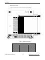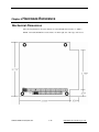
1
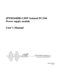
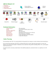
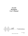
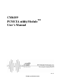
CM6109
PCMCIA utilityModuleTM
User’s Manual
BDM-610020003
Rev. B
ISO9001 and AS9100 Certified
CM6109
PCMCIA utilityModuleTM
User’s Manual
RTD Embedded Technologies, INC.
103 Innovation Blvd.
State College, PA 16803-0906
Phone: +1-814-234-8087
FAX: +1-814-234-5218
E-mail
[email protected]
[email protected]
web site
http://www.rtd.com
CM6109 user’s manual
Technologies, Inc.
-2-
RTD Embedded
Revision History
Rev. A
Rev. B
New manual naming method
02/26/2009 added note that CardBus cards are not supported
RTD Embedded Technologies, Inc.
103 Innovation Blvd.
State College, PA 16803-0906
Copyright 1999, 2002, 2003 by RTD Embedded Technologies, Inc.
All rights reserved
Printed in U.S.A.
The RTD Logo is a registered trademark of RTD Embedded Technologies. cpuModule and utilityModule are
trademarks of RTD Embedded Technologies. PhoenixPICO and PheonixPICO BIOS are trademarks of Phoenix
Technologies Ltd. PS/2, PC/XT, PC/AT and IBM are trademarks of International Business Machines Inc. MSDOS, Windows, Windows 95, Windows 98 and Windows NT are trademarks of Microsoft Corp. PC/104 is a
registered trademark of PC/104 Consortium. All other trademarks appearing in this document are the property of
their respective owners.
CM6109 user’s manual
Technologies, Inc.
-3-
RTD Embedded
CM6109 user’s manual
Technologies, Inc.
-4-
RTD Embedded
IMPORTANT NOTICE:
SOFTWARE LICENSE AGREEMENT
A) The enclosed disks contain intellectual property, i.e., software programs, that are licensed for use by the end user
customer (hereinafter "End User").
B) Sale of this product is not a sale of such intellectual property.
C) The End User shall not copy, disassemble or reverse compile the enclosed software programs.
D) THE SOFTWARE PROGRAMS ARE PROVIDED TO THE END USER "AS IS", WITHOUT WARRANTY
OF ANY KIND, EITHER EXPRESSED OR IMPLIED, INCLUDING BUT NOT LIMITED TO WARRANTIES
OF MERCHANTABILITY AND FITNESS FOR A PARTICULAR PURPOSE. THE ENTIRE RISK OF THE
QUALITY AND PERFORMANCE OF THE SOFTWARE PROGRAMS IS WITH THE END USER.
E) RTD Embedded Technologies, Inc.EAL TIME DEVICES INC., SYSTEMSOFT CORPORATION, AND
THEIR SUPPLIERS SHALL NOT BE HELD TO ANY LIABILITY FOR ANY DAMAGES SUFFERED OR
INCURRED BY THE END USER (INCLUDING BUT NOT LIMITED TO, GENERAL, SPECIAL,
CONSEQUENTIAL OR INCIDENTAL DAMAGES INCLUDING DAMAGES FOR LOSS OF BUSINESS
PROFITS, BUSINESS INTERRUPTION, LOSS OF BUSINESS INFORMATION AND THE LIKE), ARISING
FROM OR IN CONNECTION WITH THE DELIVERY, USE OR PERFORMANCE OF THE SOFTWARE
PROGRAMS.
CM6109 user’s manual
Technologies, Inc.
-5-
RTD Embedded
TABLE OF CONTENTS
CHAPTER 1
INTRODUCTION .............................................................................. 1-1
CM6109 PCMCIA utilityModule .......................................................................................................................1-1
Hardware Features ..........................................................................................................................................1-1
Connectors ......................................................................................................................................................1-1
Jumpers...........................................................................................................................................................1-1
Physical Characteristics ..................................................................................................................................1-1
Component Locations .....................................................................................................................................1-2
CHAPTER 2
CONNECTORS ................................................................................ 2-3
PC/104 AT Bus Connectors, CN1 and CN2 .......................................................................................................2-3
PCMCIA Slots, CN3 and CN4 ...........................................................................................................................2-4
CHAPTER 3
INSTALLING THE UTILITYMODULE .............................................. 3-5
JP1 Settings .......................................................................................................................................................... 3-5
Circuit Protection ................................................................................................................................................ 3-5
CHAPTER 4
INSTALLING THE UTILITYMODULE SOFTWARE......................... 4-6
PCMCIA Controller Register address............................................................................................................... 4-6
Setting I/O and Memory Windows..................................................................................................................... 4-6
Example ..........................................................................................................................................................4-7
I/O Address Map ................................................................................................................................................. 4-7
Assigning Interrupt Channels to COM Ports.................................................................................................... 4-7
Example ..........................................................................................................................................................4-8
Assigning Interrupts for the PCMCIA Slots .......................................................................................................4-8
Example ..........................................................................................................................................................4-8
CHAPTER 5
USING THE UTILITYMODULE ........................................................ 5-9
How Software Assigns Drive Letters ................................................................................................................. 5-9
Card Recognition Beep Codes ............................................................................................................................ 5-9
CHAPTER 6
HARDWARE REFERENCE ........................................................... 6-10
Mechanical Dimensions..................................................................................................................................... 6-10
CM6109 user’s manual
Technologies, Inc.
-6-
RTD Embedded
CHAPTER 7
RETURN POLICY AND WARRANTY ............................................ 7-12
Return Policy...................................................................................................................................................... 7-12
CHAPTER 8
LIMITED WARRANTY.................................................................... 8-13
CM6109 user’s manual
Technologies, Inc.
-7-
RTD Embedded
CM6109 user’s manual
Technologies, Inc.
-8-
RTD Embedded
CM6109 PCMCIA utilityModule User's Manual
Chapter 1 INTRODUCTION
This manual gives information needed to use the CM6109 PCMCIA utilityModule, which offers
one or two PCMCIA slots on a single PC/104 format card. The term PCMCIA card and PC card
are used interchangeably throughout the manual.
CM6109 PCMCIA utilityModule
The CM6109 PCMCIA utilityModule was designed to provide PCMCIA support for RTD
Embedded Technologies, Inc. cpuModules or other standard PC/104 modules.
Hardware Features
•
•
•
•
•
•
•
•
•
•
•
One or two PCMCIA slots with ejectors
Supports Type I, II, and III PCMCIA cards (!!Does not support CardBus cards!!)
Accepts two Type I, Type II, or Type III cards in the top and Type I or Type II in the bottom at
the same time
Supports SRAM, Flash, and ATA Flash memory cards
Supports ATA hard disk drives, SRAM, Flash, modems, and LAN and I/O cards
Supports both 5 VDC and 3.3 VDC cards
Permits insertion and removal of cards with system power on
LED indication and current limiting protection of short-circuited PC card
16-bit bus interface
All CMOS design gives low power consumption
Compatible with the standards of PCMCIA (Personal Computer Memory Card International
Association) Release 2.0 Standard
Connectors
The connectors provided are:
•
•
One or Two PCMCIA slots with ejectors
PC/104 Bus (AT)
Jumpers
•
One Jumper (JP1) used to select secondary adapter when using two cards in one system.
Physical Characteristics
•
•
•
•
Dimensions 3.8" x 5.1" x 0.6" Note: With standard PC Card Installed
4-layer PCB
Operating conditions:
• temperature: -40 to +85 degrees C
• relative humidity: 5 - 95%
Storage temperature: -55 to +85 degrees C
CM6109 PCMCIA utilityModule
1-1
RTD Embedded Technologies, Inc., Inc.
JP1 Settings
Component Locations
Figure 1 shows the locations of major components of the utilityModule.
Figure 1 Component Locations
Table 1.1 Component Locations
Connector
CN1
CN2
CN3
CN4
JP1
D2
CM6109 PCMCIA utilityModule
Function
PC/104 XT bus
PC/104 AT bus
PCMCIA Slot 1
PCMCIA Slot 2
SLOT 0/1 or 2/3 SELECT
Over-Current Indicator
1-2
Size
64 pin
32 pin
68 pin
68 pin
2 pin
LED
RTD Embedded Technologies, Inc.
Chapter 2 CONNECTORS
The following sections describe the connectors of the utilityModule.
PC/104 AT Bus Connectors, CN1 and CN2
Connectors CN1 and CN2 provide the PC/104 AT bus connections. CN1 carries the XT bus
signals, while CN2 carries the additional signals needed for the AT bus. The functions and
definitions of the signals on these connectors conform to the IEEE P966 standard for the PC/104
bus.
The following table lists the pinouts of connector CN1:
Pin
1
2
3
4
5
6
7
8
9
10
11
12
13
14
15
16
17
18
19
20
21
22
23
24
25
26
27
28
29
30
31
32
CM6109 PCMCIA utilityModule
Table 1-11 PC/104 Bus Connector CN1
Row A
Row B
IOCHCHK*
SD7
SD6
SD5
SD4
SD3
SD2
SD1
SD0
IOCHRDY
AEN
SA19
SA18
SA17
SA16
SA15
SA14
SA13
SA12
SA11
SA10
SA9
SA8
SA7
SA6
SA5
SA4
SA3
SA2
SA1
SA0
0V
- 2-3 -
0V
RESETDRV
+5V
IRQ9
-5V
DRQ2
-12V
ENDXFR*
+12V
(KEY)
SMEMW*
SMEMR*
IOW*
IOR*
DACK3
DRQ3
DACK1*
DRQ1
REFRESH
SYSCLK
IRQ7
IRQ6
IRQ5
IRQ4
IRQ3
DACK2*
TC
BALE
+5V
OSC
0V
0V
RTD Embedded Technologies, Inc.
JP1 Settings
The following table lists the pinouts of connector CN2:
Pin
Table 1-12 PC/104 Bus Connector CN2
Row C
Row D
1
2
3
4
5
6
7
8
9
10
11
12
13
14
15
16
17
18
19
20
0V
SBHE*
LA23
LA22
LA21
LA20
LA19
LA18
LA17
MEMR*
MEMW*
SD8
SD9
SD10
SD11
SD12
SD13
SD14
SD15
KEY(nc)
0V
MEMCS16*
IOCS16*
IRQ10
IRQ11
IRQ12
IRQ15
IRQ14
DACK0*
DRQ0
DACK5*
DRQ5
DACK6*
DRQ6
DACK7*
DRQ7
+5V
MASTER*
0V
0V
PCMCIA Slots, CN3 and CN4
CN3 and CN4 are the two PCMCIA slots, which accept standard Type I, II, and III PCMCIA cards
with 68-pin connectors. The top slot (farthest from the circuit board) is considered the first slot,
while the bottom slot (closest to the circuit board) is considered the second slot. See the Using the
utilityModule section for information on the assignment of drive letters to the slots.
CM6109 PCMCIA utilityModule
2-4
RTD Embedded Technologies, Inc.
Chapter 3 INSTALLING THE UTILITYMODULE
Since the utilityModule uses a PC/104 stackthrough bus, the only hardware installation you will do
is placing the CM6109 on the PC/104 stack. To do this, you will simply plug the PC/104 bus
connector composed of CN1 and CN2 onto the matching connector of your cpuModule.
We recommend you follow the procedure below to ensure that stacking of the modules does not
damage connectors or electronics.
•
•
•
•
•
•
•
•
Turn off power to the PC/104 system or stack.
Select and install standoffs to properly position the utilityModule on the PC/104 stack.
Touch a metal part of the rack to discharge any buildup of static electricity.
Remove the utilityModule from its anti-static bag.
Check that any keying pins in the bus connector are properly positioned.
Check the stacking order; make sure an XT bus card will not be placed between two AT bus
cards or it will interrupt the AT bus signals.
Hold the utilityModule by its edges and orient it so the bus connector pins line up with the
matching connector on the stack.
Gently and evenly press the utilityModule onto the PC/104 stack.
CAUTION:
Do not force the module onto the stack! Wiggling the module or applying too
much pressure may damage it. If the module does not readily press into place, remove it,
check for bent pins or out-of-place keying pins, and try again.
JP1 Settings
JP1 is used to configure the CM6109 as the first adapter or as the secondary adapter when using
two CM6109s in the same system. The Default setting is no jumper installed which sets the
CM6109 chip select to Sockets 0 and 1. Installing JP1 enables a chip select to set the second
CM6109 to Sockets 2 and 3.
Circuit Protection
PC Cards are inherently subject to damage that results from mishandling the card. Circuitry has
been added to protect the circuitry and warn the user of a short circuit condition. D2 is an LED
indicator of a short-circuit condition of one of the sockets. Immediately remove the PC Card or
power down the system if D2 is on.
CM6109 PCMCIA utilityModule
- 3-5 -
RTD Embedded Technologies, Inc.
PCMCIA Controller Register address
Chapter 4 INSTALLING THE UTILITYMODULE
SOFTWARE
The CM6109 is supplied PCMCIA-compliant software drivers. See the users manual in .PDF file
format included on Disk #1 for DOS installation and usage and Windows NT 4.0 drivers manual
include also on the DOS Disk #1 of the installation disks. Windows 95 / 98 has PCMCIA support
built into its operating system.
The following sections are basic applications of system integration for use with other drivers. For
other operating systems please contact your software supplier for drivers for the specific operating
system.
PCMCIA Controller Register address
The CL-PD6722 internal registers are accessed through a pair of Operation registers---an Index
register and a Data register. The Index register is accessed at address 03E0h, and the Data register
is accessed at 03E1h.
For more information about specific register mapping see the www.basiscomm.com website to
download the databook in .PDF file format.
Setting I/O and Memory Windows
Some PCMCIA devices such as LAN cards and I/O cards require an I/O window and/or a memory
window. The default I/O window for the CM6109 is located at I/O addresses 300h to 31Fh. The
default memory window is located at addresses D0000h to D7FFFh.
Note that these default I/O and memory addresses are frequently the defaults for other PC/104
modules and Solid State Disks. You may therefore need to change the location and size of the I/O
window and memory window to prevent conflicts and ensure proper operation.
You can change the I/O and memory windows by appending the following text to the command
line in the CONFIG.SYS file that loads the device driver:
/IOW=uuu-vvv /MEMW=xxxx-yyyy
Where:
uuu is the I/O window starting address (3 hex digits), and vvv is the I/O window ending
address (3 hex digits).
xxxx is the memory window starting address (first 4 hex digits), and yyyy is the memory
window ending address (first 4 hex digits).
Note that if the /IOW= text is added without the uuu-vvv argument, the I/O window is disabled
entirely. Also, if the /MEMW= text is added without the xxxx-yyyy argument, the memory
window is disabled.
CM6109 PCMCIA utilityModule
4-6
RTD Embedded Technologies, Inc.
Example
To open an I/O window from 300h to 33Fh and a memory window from E0000h to E3FFFh, you
would modify the line in your CONFIG.SYS file which loads the device driver to read:
DEVICE=C:\ SOMEFOLDER\SOMEDRIVER.SYS /A /IOW=300-33F /MEMW=E000E3FF
I/O Address Map
NOTE: To ensure correct operation, you must make absolutely certain that I/O and memory
addresses used by the CM6109 are not used by other devices in the system (dataModules,
cpuModule, Solid State Disk, etc.).
The CM6109 always uses I/O addresses 0240h through 024Fh. For proper operation, you must
make absolutely certain no other board in your PC/104 system uses those I/O addresses.
If you are using a PCMCIA I/O card which requires an I/O address window, you must also ensure
that the addresses in that window are not used by other boards in your PC/104 system.
If you are using a PCMCIA ATA drive, I/O address 0170h is also used. You must ensure that that
address is not used by any other board in your PC/104 system.
Note that the CM6109 only decodes address lines A0 through A9 on I/O accesses.
Assigning Interrupt Channels to COM Ports
When you use a PCMCIA card (such as a modem) that requires a COM port, the CM6109 driver
software must assign a COM port to the PCMCIA card. When such a card is detected, the software
will assign the next COM port not already is use by the system. When the software assigns the port
it also assigns an associated interrupt (IRQ) channel. The default interrupt channel for each COM
port is shown below:
Default Interrupts for COM Ports
COM Port
COM1
COM2
COM3
COM4
CM6109 PCMCIA utilityModule
Default Interrupt
IRQ4
IRQ3
IRQ4
IRQ3
- 4-7 -
RTD Embedded Technologies, Inc.
Assigning Interrupt Channels to COM Ports
You may override the default and select the interrupt channel assigned to a particular COM port by
appending the following text string to the line in your CONFIG.SYS file which loads the device
driver:
/COMnIRQ=c
Where the letter 'n' is replaced with the COM port number and the letter 'c' is replaced
with the interrupt channel to be assigned. The COM port number can be 1, 2, 3, or 4, and
the interrupt number can be: 3, 4, 5, 6, 7, 10, 11 or 14.
NOTE: The interrupt used for the slot-event interrupt (by default IRQ11) cannot be assigned to a
COM port. Refer to the next section for information on the slot-event interrupt.
Example
If you wish to assign interrupt channel 5 (IRQ5) to COM port 3, you would modify the line in your
CONFIG.SYS file which loads the device driver to read:
DEVICE=\SOMEFOLDER\SOMEDRIVER.SYS /A /COM3IRQ=5
Assigning Interrupts for the PCMCIA Slots
The PCMCIA controller on the CM6109 requires one interrupt line to signal slot events such as
card insertion. The default interrupt used by the CM6109 is IRQ11. The slot-event interrupt can be
changed by modifying your CONFIG.SYS file.
To change the interrupt, append the following text string to the command line which loads the
driver:
/SCIRQ=c
Where the letter 'c' is replaced with the desired interrupt number: 3,4,5,6,7,10,11, or 14
Example
If you wished to use interrupt IRQ5 as the slot-event interrupt, you would change your
CONFIG.SYS file so the line used to load the driver reads:
DEVICE=\ SOMEFOLDER\SOMEDRIVER.SYS /SCIRQ=5
CM6109 PCMCIA utilityModule
4-8
RTD Embedded Technologies, Inc.
Chapter 5 USING THE UTILITYMODULE
The following sections describe the use of the CM6109 utilityModule.
How Software Assigns Drive Letters
When the CM6109 drivers are loaded, the software assigns drive letters to the PCMCIA slots. On
the standard CM6109 utilityModule with two slots, the upper slot is assigned the second drive
letter not in use by Solid State Disks, floppy drives, or hard disks already in the system. The lower
socket is assigned the first unused drive letter. On boards ordered with the option of a single slot,
that slot is assigned the first unused drive letter.
Card Recognition Beep Codes
If a speaker is present in your PC/104 system, the CM6109 utilityModule will cause it to beep
when PCMCIA cards are inserted. The number of beeps indicate whether the card has a valid CIS
(Card Identification String), which identifies it as a valid PCMCIA card type, and whether it is
formatted properly.
CM6109 PCMCIA utilityModule
- 5-9 -
RTD Embedded Technologies, Inc.
Chapter 6 HARDWARE
REFERENCE
Mechanical Dimensions
The following illustration shows the dimensions of the utilityModule in inches (+/- 0.005").
NOTE: An installed PCMCIA card extends 0.9" from the right side of the edge of the board.
CM6109 PCMCIA utilityModule
6-10
RTD Embedded Technologies, Inc.
1
CM6109 PCMCIA utilityModule
- 6-11 -
RTD Embedded Technologies, Inc.
Return Policy
Chapter 7 RETURN
POLICY AND WARRANTY
Return Policy
If you wish to return a product to the factory for service, please follow this procedure:
Read the Limited Warranty to familiarize yourself with our warranty policy.
Contact the factory for a Return Merchandise Authorization (RMA) number.
Please have the following available:
•
•
•
Complete board name
Board serial number
A detailed description of the board’s behavior
List the name of a contact person, familiar with technical details of the problem or situation, along
with their phone and fax numbers, address, and e-mail address (if available).
List your shipping address!!
Indicate the shipping method you would like used to return the product to you.
We will not ship by next-day service without your pre-approval.
Carefully package the product, using proper anti-static packaging.
Write the RMA number in large (1") letters on the outside of the package.
Return the package to:
RTD Embedded Technologies, Inc.
103 Innovation Blvd.
State College PA 16803-0906
USA
CM6109 PCMCIA utilityModule
7-12
RTD Embedded Technologies, Inc.
Chapter 8 LIMITED
WARRANTY
RTD Embedded Technologies, Inc. warrants the hardware and software products it manufactures and
produces to be free from defects in materials and workmanship for one year following the date of shipment
from RTD Embedded Technologies, INC. This warranty is limited to the original purchaser of product and
is not transferable.
During the one year warranty period, RTD Embedded Technologies will repair or replace, at its option, any
defective products or parts at no additional charge, provided that the product is returned, shipping prepaid,
to RTD Embedded Technologies. All replaced parts and products become the property of RTD Embedded
Technologies. Before returning any product for repair, customers are required to contact the factory for an
RMA number.
THIS LIMITED WARRANTY DOES NOT EXTEND TO ANY PRODUCTS WHICH HAVE BEEN
DAMAGED AS A RESULT OF ACCIDENT, MISUSE, ABUSE (such as: use of incorrect input voltages,
improper or insufficient ventilation, failure to follow the operating instructions that are provided by RTD
Embedded Technologies, "acts of God" or other contingencies beyond the control of RTD Embedded
Technologies), OR AS A RESULT OF SERVICE OR MODIFICATION BY ANYONE OTHER THAN
RTD Embedded Technologies. EXCEPT AS EXPRESSLY SET FORTH ABOVE, NO OTHER
WARRANTIES ARE EXPRESSED OR IMPLIED, INCLUDING, BUT NOT LIMITED TO, ANY
IMPLIED WARRANTIES OF MERCHANTABILITY AND FITNESS FOR A PARTICULAR
PURPOSE, AND RTD Embedded Technologies EXPRESSLY DISCLAIMS ALL WARRANTIES NOT
STATED HEREIN. ALL IMPLIED WARRANTIES, INCLUDING IMPLIED WARRANTIES FOR
MECHANTABILITY AND FITNESS FOR A PARTICULAR PURPOSE, ARE LIMITED TO THE
DURATION OF THIS WARRANTY. IN THE EVENT THE PRODUCT IS NOT FREE FROM
DEFECTS AS WARRANTED ABOVE, THE PURCHASER'S SOLE REMEDY SHALL BE REPAIR OR
REPLACEMENT AS PROVIDED ABOVE. UNDER NO CIRCUMSTANCES WILL RTD Embedded
Technologies BE LIABLE TO THE PURCHASER OR ANY USER FOR ANY DAMAGES,
INCLUDING ANY INCIDENTAL OR CONSEQUENTIAL DAMAGES, EXPENSES, LOST PROFITS,
LOST SAVINGS, OR OTHER DAMAGES ARISING OUT OF THE USE OR INABILITY TO USE THE
PRODUCT.
SOME STATES DO NOT ALLOW THE EXCLUSION OR LIMITATION OF INCIDENTAL OR
CONSEQUENTIAL DAMAGES FOR CONSUMER PRODUCTS, AND SOME STATES DO NOT
ALLOW LIMITATIONS ON HOW LONG AN IMPLIED WARRANTY LASTS, SO THE ABOVE
LIMITATIONS OR EXCLUSIONS MAY NOT APPLY TO YOU.
THIS WARRANTY GIVES YOU SPECIFIC LEGAL RIGHTS, AND YOU MAY ALSO HAVE OTHER
RIGHTS WHICH VARY FROM STATE TO STATE.
CM6109 PCMCIA utilityModule
- 8-13 -
RTD Embedded Technologies, Inc.
Return Policy
RTD Embedded Technologies, Inc.
103 Innovation Blvd.
State College PA 16803-0906
USA
Our website: www.rtd.com
CM6109 PCMCIA utilityModule
8-14
RTD Embedded Technologies, Inc.