1
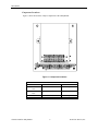
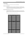
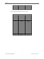
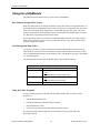
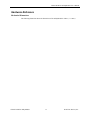
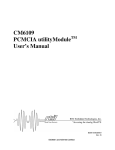
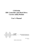
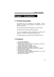
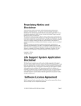
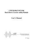
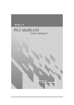
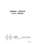
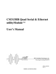
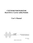
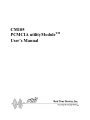
CM105
PCMCIA utilityModuleTM
User’s Manual
Publication No. CM105 9532
,03257$17 127,&(
SOFTWARE LICENSE AGREEMENT
A) The enclosed disks contain intellectual property, i.e., software programs, that are licensed for use by the end
user customer (hereinafter "End User").
B) Sale of this product is not a sale of such intellectual property.
C) The End User shall not copy, disassemble or reverse compile the enclosed software programs.
D) THE SOFTWARE PROGRAMS ARE PROVIDED TO THE END USER "AS IS", WITHOUT WARRANTY
OF ANY KIND, EITHER EXPRESSED OR IMPLIED, INCLUDING BUT NOT LIMITED TO WARRANTIES
OF MERCHANTABILITY AND FITNESS FOR A PARTICULAR PURPOSE. THE ENTIRE RISK OF THE
QUALITY AND PERFORMANCE OF THE SOFTWARE PROGRAMS IS WITH THE END USER.
E) REAL TIME DEVICES INC., M. K. HANSEN COMPANY, DATABOOK CORPORATION, AND THEIR
SUPPLIERS SHALL NOT BE HELD TO ANY LIABILITY FOR ANY DAMAGES SUFFERED OR INCURRED
BY THE END USER (INCLUDING BUT NOT LIMITED TO, GENERAL, SPECIAL, CONSEQUENTIAL OR
INCIDENTAL DAMAGES INCLUDING DAMAGES FOR LOSS OF BUSINESS PROFITS, BUSINESS
INTERRUPTION, LOSS OF BUSINESS INFORMATION AND THE LIKE), ARISING FROM OR IN
CONNECTION WITH THE DELIVERY, USE OR PERFORMANCE OF THE SOFTWARE PROGRAMS.
CM105
PCMCIA utilityModuleTM
User’s Manual
REAL TIME DEVICES, INC.
Post Office Box 906
State College, PA 16804
Phone: (814) 234-8087
FAX: (814) 234-5218
Published by
Real Time Devices, Inc.
P.O. Box 906
State College, PA 16804
Copyright 1995 by Real Time Devices, Inc.
All rights reserved
Printed in U.S.A.
MS-DOS and Windows are registered trademark of Microsoft Corp.
PC/104 is a registered trademark of PC/104 Consortium.
The Real Time Devices Logo is a registered trademark of Real Time Devices.
cpuModule is a trademark of Real Time Devices.
utilityModule is a trademark of Real Time Devices.
CardTalk and Databook are trademarks of Databook Inc.
All other trademarks appearing in this document are the property of their respective owners.
Table of Contents
Introduction ..................................................................................................................................................... 1
CM105 PCMCIA utilityModule..................................................................................................................... 1
Hardware Features ..................................................................................................................................... 1
Software Features....................................................................................................................................... 1
Connectors................................................................................................................................................. 1
Physical Characteristics ............................................................................................................................. 1
Component Locations ................................................................................................................................ 2
Connectors ....................................................................................................................................................... 3
PCMCIA Slots, J5 and J7 .............................................................................................................................. 3
PC/104 AT Bus Connectors, J1, J2, J3, J4...................................................................................................... 3
Installing the utilityModule ............................................................................................................................. 5
Installing the utilityModule Software ............................................................................................................. 6
Installing Software on a Non-PCMCIA Boot Drive........................................................................................ 6
Installing Software on a PCMCIA Card ......................................................................................................... 7
Setting I/O and Memory Windows................................................................................................................. 7
Example .................................................................................................................................................... 7
I/O Address Map ........................................................................................................................................... 7
Assigning Interrupt Channels to COM Ports.................................................................................................. 8
Example .................................................................................................................................................... 8
Assigning Interrupts for the PCMCIA Slots ................................................................................................... 8
Example .................................................................................................................................................... 9
Using the utilityModule ................................................................................................................................. 10
How Software Assigns Drive Letters ............................................................................................................ 10
Card Recognition Beep Codes...................................................................................................................... 10
Using the Utility Programs........................................................................................................................... 10
Formatting ATA Memory Cards .............................................................................................................. 11
Formatting SRAM Memory Cards ........................................................................................................... 11
Formatting Flash Cards with Microsoft FFS2........................................................................................... 11
Formatting Flash Cards without Microsoft FFS2...................................................................................... 12
Hardware Reference ..................................................................................................................................... 13
Mechanical Dimensions............................................................................................................................... 13
Limited Warranty ........................................................................................................................................... 1
CM105 PCMCIA utilityModule User's Manual
Introduction
This manual gives information needed to use the CM105 PCMCIA utilityModule, which offers
two PCMCIA slots on a single PC/104 format card.
CM105 PCMCIA utilityModule
The CM105 PCMCIA utilityModule was designed to provide PCMCIA support for the Real Time
Devices cpuModules or other standard PC/104 modules.
Hardware Features
•
Two PCMCIA slots with ejectors
•
Supports Type I, II, and III PCMCIA cards
Accepts two Type I or Type II cards at the same time
Supports SRAM, Flash, and ATA Flash memory cards
Supports ATA hard disk drives, modems, and LAN and I/O cards
On-board DC-DC converter supplies 12 volts for Flash memory cards
Permits insertion and removal of cards with system power on
16-bit bus interface
All CMOS design gives low power consumption
•
•
•
•
•
•
•
Software Features
•
•
•
•
•
Includes PCMCIA-compliant Socket Services, Card Services, and Client Services software
Windows compatible
Requires no changes to BIOS or application software
Includes utilities for erasing, initializing, and formatting PCMCIA memory cards
Can be configured to boot from formatted PCMCIA memory cards
Connectors
The connectors provided are:
•
•
Two PCMCIA slots with ejectors
PC/104 Bus (AT)
Physical Characteristics
•
•
•
•
Dimensions 3.8" x 3.9" x 0.6"
4-layer PCB
Operating conditions:
• temperature: 0 - 75 degrees C
• relative humidity: 5 - 95%
• altitude: 0 - 3000m
Storage temperature: -55 to +85 degrees C
CM105 PCMCIA utilityModule
1
Real Time Devices, Inc.
Introduction
Component Locations
Figure 1 shows the locations of major components of the utilityModule.
Figure 1 Component Locations
Table 1.1 Connectors
Connector
J1/B
J2/A
J3/D
J4/C
J5
J7
CM105 PCMCIA utilityModule
Function
PC/104 XT bus
Size
64 pin
PC/104 AT bus
32 pin
PCMCIA Slot 1
PCMCIA Slot 2
68 pin
68 pin
2
Real Time Devices, Inc.
CM105 PCMCIA utilityModule User’s Manual
Connectors
The following sections describe the connectors of the utilityModule.
PCMCIA Slots, J5 and J7
J5 and J7 are the two PCMCIA slots, which accept standard Type I, II, and III PCMCIA cards
with 68-pin connectors. The top slot (farthest from the circuit board) is considered the first slot,
while the bottom slot (closest to the circuit board) is considered the second slot. See the Using the
utilityModule section for information on the assignment of drive letters to the slots.
PC/104 AT Bus Connectors, J1, J2, J3, J4
Connectors J1 through J4 provide the PC/104 AT bus connections. J1 and J2 carry the XT bus
signals, while J3 and J4 carry the additional signals neeeded for the AT bus. The functions and
definitions of the signals on these connectors conform to the IEEE P966 standard for the PC/104
bus.
The following table lists the pinouts of connectors J1 and J2:
Table 1-11 PC/104 Bus Connector, J1 and J2
Pin
Row A
Row B
1
2
3
4
5
6
7
8
9
10
11
12
13
14
15
16
17
18
19
20
21
22
23
24
25
26
27
28
CM105 PCMCIA utilityModule
IOCHCHK*
SD7
SD6
SD5
SD4
SD3
SD2
SD1
SD0
IOCHRDY
AEN
SA19
SA18
SA17
SA16
SA15
SA14
SA13
SA12
SA11
SA10
SA9
SA8
SA7
SA6
SA5
SA4
SA3
3
0V
RESETDRV
+5V
IRQ9
-5V
DRQ2
-12V
ENDXFR*
+12V
(KEY)
SMEMW*
SMEMR*
IOW*
IOR*
DACK3
DRQ3
DACK1*
DRQ1
REFRESH
SYSCLK
IRQ7
IRQ6
IRQ5
IRQ4
IRQ3
DACK2*
TC
BALE
Real Time Devices, Inc.
Connectors
29
30
31
32
SA2
SA1
SA0
0V
+5V
OSC
0V
0V
The following table lists the pinouts of connectors J3 and J4:
Table 1-12 PC/104 Bus Connector, J3 and J4
Pin
Row C
Row D
1
2
3
4
5
6
7
8
9
10
11
12
13
14
15
16
17
18
19
20
CM105 PCMCIA utilityModule
0V
SBHE*
LA23
LA22
LA21
LA20
LA19
LA18
LA17
MEMR*
MEMW*
SD8
SD9
SD10
SD11
SD12
SD13
SD14
SD15
KEY(nc)
4
0V
MEMCS16*
IOCS16*
IRQ10
IRQ11
IRQ12
IRQ15
IRQ14
DACK0*
DRQ0
DACK5*
DRQ5
DACK6*
DRQ6
DACK7*
DRQ7
+5V
MASTER*
0V
0V
Real Time Devices, Inc.
CM105 PCMCIA utilityModule User’s Manual
Installing the utilityModule
Since the utilityModule uses a PC/104 stackthrough bus, the only hardware installation you will
do is placing the CM105 on the PC/104 stack. To do this, you will simply plug the PC/104 bus
connector composed of J1, J2, J3, and J4 onto the matching connector of your cpuModule.
We recommend you follow the procedure below to ensure that stacking of the modules does not
damage connectors or electronics.
•
•
•
•
•
•
•
•
Turn off power to the PC/104 system or stack.
Select and install standoffs to properly position the utilityModule on the PC/104 stack.
Touch a metal part of the rack to discharge any buildup of static electricity.
Remove the utilityModule from its anti-static bag.
Check that any keying pins in the bus connector are properly positioned.
Check the stacking order; make sure an XT bus card will not be placed between two AT bus
cards or it will interrupt the AT bus signals.
Hold the utilityModule by its edges and orient it so the bus connector pins line up with the
matching connector on the stack.
Gently and evenly press the utilityModule onto the PC/104 stack.
CAUTION:
Do not force the module onto the stack! Wiggling the module or applying too
much pressure may damage it. If the module does not readily press into place, remove it,
check for bent pins or out-of-place keying pins, and try again.
CM105 PCMCIA utilityModule
5
Real Time Devices, Inc.
Installing the utilityModule Software
Installing the utilityModule Software
The CM105 is supplied PCMCIA-compliant software drivers for Socket Services, Card Services,
and Client Services. Usually you will want to install these device drivers on the cpuModule's
Solid-State Disk. You also may install the drivers on a hard drive, floppy drive, PCMCIA SRAM
drive, or PCMCIA Flash drive. The following sections explain the procedures for installing the
software drivers.
Installing Software on a Non-PCMCIA Boot Drive
If you wish to install the software drivers on a non-PCMCIA boot drive such as a hard drive, use
the following procedure:
1) Create a sub-directory named CARDTALK on the disk from which the system will boot.
2) Copy the files MKHPV.SYS, CTALKCS.EXE and CARDTALK.SYS from the CM105
Software Drivers disk to the CARDTALK sub-directory you just created.
3) If you plan to use your PC/104 sytem with Windows, copy the CARDTALK.386 file from the
CM105 Software Drivers disk to the CARDTALK sub-directory.
4) If you want to use the Microsoft FFS2 Flash File System, you must copy the file MSFLASH.SYS to the CARDTALK sub-directory. Please note that Microsoft Flash File System
software is not included with the CM105 and must be purchased separately.
5) Using a text editor, add the following lines at the beginning of your CONFIG.SYS file:
DEVICE=\CARDTALK\MKHPV.SYS
DEVICE=\CARDTALK\CTALKCS.EXE
DEVICE=\CARDTALK\CARDTALK.SYS /A
FILES=20
BUFFER=20
LASTDRIVE=Z
6) If you are going to use the Microsoft FFS2 Flash File System, also add the following line to
your CONFIG.SYS file:
DEVICE=\CARDTALK\MS-FLASH.SYS
7) Add the CARDTALK sub-directory to the PATH specified in the cpuModule's
AUTOEXEC.BAT file. See your DOS manual if you need details on using the PATH command.
After these steps are completed, you can re-boot the system and the CM105 drivers should load.
While they are loading, information is displayed on the screen, including the drive letters
assigned to the PCMCIA slots. If the CM105 is not installed correctly or cannot find software
drivers, error messages will appear on the screen.
CM105 PCMCIA utilityModule
6
Real Time Devices, Inc.
CM105 PCMCIA utilityModule User’s Manual
Installing Software on a PCMCIA Card
It is possible to install the CM105 software drivers on a properly-formatted PCMCIA SRAM or
Flash memory card, thereby allowing the system to boot from the PCMCIA card. To do this, you
must install the CM105 Socket Services driver as a BIOS extension in ROM.
If you are using a Real Time Devices cpuModule with your CM105, refer to your cpuModule
User's Manual for information on making the Socket Services driver into a BIOS Extension. If
you are using another brand of processor board, please contact the processor board manufacturer
for assistance creating a BIOS extension.
Setting I/O and Memory Windows
Some PCMCIA devices such as LAN cards and I/O cards require an I/O window and/or a
memory window. The default I/O window for the CM105 is located at I/O addresses 300h to
31Fh. The default memory window is located at addresses D0000h to D7FFFh.
Note that these default I/O and memory addresses are frequently the defaults for other PC/104
modules and Solid State Disks. You may therefore need to change the location and size of the I/O
window and memory window to prevent conflicts and ensure proper operation.
You can change the I/O and memory windows by appending the following text to the command
line in the CONFIG.SYS file that loads the CARDTALK.SYS device driver:
/IOW=uuu-vvv /MEMW=xxxx-yyyy
Where:
uuu is the I/O window starting address (3 hex digits), and vvv is the I/O window ending
address (3 hex digits).
xxxx is the memory window starting address (first 4 hex digits), and yyyy is the memory
window ending address (first 4 hex digits).
Note that if the /IOW= text is added without the uuu-vvv argument, the I/O window is disabled
entirely. Also, if the /MEMW= text is added without the xxxx-yyyy argument, the memory
window is disabled.
Example
To open an I/O window from 300h to 33Fh and a memory window from E0000h to E3FFFh, you
would modify the line in your CONFIG.SYS file which loads the CARDTALK.SYS device driver
to read:
DEVICE=C:\CARDTALK\CARDTALK.SYS /A /IOW=300-33F /MEMW=E000-E3FF
I/O Address Map
NOTE: To ensure correct operation, you must make absolutely certain that I/O and memory
addresses used by the CM105 are not used by other devices in the system (dataModules,
cpuModule, Solid State Disk, etc.).
The CM105 always uses I/O addresses 0240h through 024Fh. For proper operation, you must
make absolutely certain no other board in your PC/104 system uses those I/O addresses.
CM105 PCMCIA utilityModule
7
Real Time Devices, Inc.
Installing the utilityModule Software
If you are using a PCMCIA I/O card which requires an I/O address window, you must also
ensure that the addresses in that window are not used by other boards in your PC/104 system.
If you are using a PCMCIA ATA drive, I/O address 0170h is also used. You must ensure that
that address is not used by any other board in your PC/104 system. Note that this particular I/O
address can be changed if absolutely necessary. Contact factory technical support for details.
Note that the CM105 only decodes address lines A0 through A9 on I/O accesses.
Assigning Interrupt Channels to COM Ports
When you use a PCMCIA card (such as a modem) that requires a COM port, the CM105 driver
software must assign a COM port to the PCMCIA card. When such a card is detected, the
software will assign the next COM port not already is use by the system. When the software
assigns the port it also assigns an associated interrupt (IRQ) channel. The default interrupt
channel for each COM port is shown below:
Default Interrupts for COM Ports
COM Port
COM1
COM2
COM3
COM4
Default Interrupt
IRQ4
IRQ3
IRQ4
IRQ3
You may override the default and select the interrupt channel assigned to a particular COM port
by appending the following text string to the line in your CONFIG.SYS file which loads the
CARDTALK.SYS device driver:
/COMnIRQ=c
Where the letter 'n' is replaced with the COM port number and the letter 'c' is replaced
with the interrupt channel to be assigned. The COM port number can be 1, 2, 3, or 4,
and the interrupt number can be: 3, 4, 5, 6, 7, 10, 11 or 14.
NOTE: The interrupt used for the slot-event interrupt (by default IRQ11) cannot be assigned to
a COM port. Refer to the next section for information on the slot-event interrupt.
Example
If you wish to assign interrupt channel 5 (IRQ5) to COM port 3, you would modify the line in
your CONFIG.SYS file which loads the CARDTALK.SYS device driver to read:
DEVICE=\CARDTALK\CARDTALK.SYS /A /COM3IRQ=5
Assigning Interrupts for the PCMCIA Slots
The PCMCIA controller on the CM105 requires one interrupt line to signal slot events such as
card insertion. The default interrupt used by the CM105 is IRQ11. The slot-event interrupt can be
changed by modifying your CONFIG.SYS file.
CM105 PCMCIA utilityModule
8
Real Time Devices, Inc.
CM105 PCMCIA utilityModule User’s Manual
To change the interrupt, append the following text string to the command line which loads the
MKHPV.SYS driver:
/SCIRQ=c
Where the letter 'c' is replaced with the desired interrupt number: 3,4,5,6,7,10,11, or 14
Example
If you wished to use interrupt IRQ5 as the slot-event interrupt, you would change your
CONFIG.SYS file so the line used to load the MKHPV.SYS driver reads:
DEVICE=\CARDTALK\MKHPV.SYS /SCIRQ=5
CM105 PCMCIA utilityModule
9
Real Time Devices, Inc.
Using the utilityModule
Using the utilityModule
The following sections describe the use of the CM105 utilityModule.
How Software Assigns Drive Letters
When the CM105 drivers are loaded, the software assigns drive letters to the PCMCIA slots. On
the standard CM105 utilityModule with two slots, the upper slot is assigned the first drive letter
not in use by Solid State Disks, floppy drives, or hard disks already in the system. The lower
socket is assigned the second unused drive letter. On boards ordered with the option of a single
slot, that slot is assigned the first unused drive letter.
If your application requires use of memory cards with multiple partitions, more than one drive
letter can be assigned to a single socket. If you find you need to do this, please contact factory
technical support for assistance.
Card Recognition Beep Codes
If a speaker is present in your PC/104 system, the CM105 utilityModule will cause it to beep
when PCMCIA cards are inserted. The number of beeps indicate whether the card has a valid
CIS (Card Indentification String), which identifies it as a valid PCMCIA card type, and whether
it is formatted properly.
The following table lists the Card Recognition Beep Codes and their meanings:
Card Recognition Beep Codes
Number of Beeps
1
2
3
Meanings
ATA or modem card with valid CIS was inserted
OR
Formatted SRAM or Flash card inserted
Unformatted SRAM or Flash card inserted
OR
LAN card with valid CIS inserted
Card without valid CIS inserted
Using the Utility Programs
A range of utility programs are provided on the CM105 Utilities disk. You may use these
programs to:
•
Format SRAM memory cards
•
Format Flash memory cards with Flash File System
•
Erase Flash memory cards
•
Format and copy files to Flash cards without Flash File System
You may install these utility programs in an end product or may use them only in the
development system.
CM105 PCMCIA utilityModule
10
Real Time Devices, Inc.
CM105 PCMCIA utilityModule User’s Manual
The following sections briefly discuss use of the utility programs to perform common tasks. For
in-depth documentation of the utilities programs, please contact factory technical support to
obtain the Databook CardTalktm Reference Manual.
NOTE: In the following sections, it is assumed that the PATH command in the
AUTOEXEC.BAT file includes the drive and sub-directory containing the utility
programs.
Formatting ATA Memory Cards
You can format ATA Flash and ATA hard drive cards without using the utility programs, by
using the standard DOS FORMAT command. Please refer to your DOS manual for information
on the FORMAT command.
Note that once formatted, ATA cards appear to DOS as conventional hard drives. Please keep in
mind that PC/104 systems cannot be booted from ATA memory or hard-drive cards.
Formatting SRAM Memory Cards
You format SRAM memory cards using the TCFORMAT.EXE utility program provided on the
CM105 Utilities disk.
For example, to format an SRAM card in the D: drive socket, enter the following at the DOS
prompt:
TCFORMAT D:
Note that after an SRAM card has been formatted, it appears to DOS as a conventional hard
drive.
Formatting Flash Cards with Microsoft FFS2
To format a Flash card with the Microsoft FFS2 Flash File System, you must perform two steps.
First, you must erase the card using the TCERASE utility program and then you must format the
card using the TCFORMAT utility. Both utilities are provide on the CM105 Utilities disk.
To erase a Flash card in the D: drive socket using the TCERASE.EXE utility, enter the following
at the DOS prompt:
TCERASE D:
After erasing the card, you must format it using the TCFORMAT.EXE program provided on the
CM105 Utilities disk.
For example, to format a Flash card (located in the D: drive socket) with the FFS2 Flash File
System, enter the following at the DOS prompt:
TCFORMAT -TYPE FLASH D:
Once you have formatted a Flash card with the Microsoft FFS2 Flash File System, it appears to
DOS as a conventional hard drive (as long as MS-FLASH.SYS has been loaded). Please note,
however, that the CHKDSK command cannot be used on Flash cards formatted with the Flash
File System.
CM105 PCMCIA utilityModule
11
Real Time Devices, Inc.
Using the utilityModule
Formatting Flash Cards without Microsoft FFS2
To format a Flash card without the Flash File System, you must perform two steps. First, you
must erase the card using the TCERASE utility program and then you must format the card using
the TCXCOPY utility. Both utilities are provide on the CM105 Utilities disk.
To erase a Flash card in the D: drive socket using the TCERASE.EXE utility, enter the following
at the DOS prompt:
TCERASE D:
After erasing the card, you must format and copy files to it using the TCXCOPY.EXE program
provided on the CM105 Utilities disk.
For example, to format a Flash card located in the D: drive socket and simultaneously copy all
the files in sub-directory C:\TMP to the card, enter the following at the DOS prompt:
TCXCOPY C:\TMP\*.* D:
Once you have formatted a Flash card with the TCXCOPY.EXE program, it appears to DOS as a
read-only device. You cannot edit or delete individual files on the card, but you can append
additional files using the TCXCOPY.EXE program as described above.
NOTE: When displaying the directory of a Flash card formatted with the TCXCOPY.EXE
utility, DOS will indicate "0 bytes free" no matter how much space is actually available.
This is normal.
CM105 PCMCIA utilityModule
12
Real Time Devices, Inc.
CM105 PCMCIA utilityModule User’s Manual
Hardware Reference
Mechanical Dimensions
The following illustration shows the dimensions of the utilityModule in inches (+/- 0.005").
CM105 PCMCIA utilityModule
13
Real Time Devices, Inc.
CM105 PCMCIA utilityModule User's Manual
Limited Warranty
Real Time Devices, Inc. warrants the hardware and software products it manufactures and
produces to be free from defects in materials and workmanship for one year following the date of
shipment from REAL TIME DEVICES. This warranty is limited to the original purchaser of
product and is not transferable.
During the one year warranty period, REAL TIME DEVICES will repair or replace, at its option,
any defective products or parts at no additional charge, provided that the product is returned,
shipping prepaid, to REAL TIME DEVICES. All replaced parts and products become the
property of REAL TIME DEVICES. Before returning any product for repair, customers are
required to contact the factory for an RMA number.
THIS LIMITED WARRANTY DOES NOT EXTEND TO ANY PRODUCTS WHICH HAVE
BEEN DAMAGED AS A RESULT OF ACCIDENT, MISUSE, ABUSE (such as: use of
incorrect input voltages, improper or insufficient ventilation, failure to follow the operating
instructions that are provided by REAL TIME DEVICES, "acts of God" or other contingencies
beyond the control of REAL TIME DEVICES), OR AS A RESULT OF SERVICE OR
MODIFICATION BY ANYONE OTHER THAN REAL TIME DEVICES. EXCEPT AS
EXPRESSLY SET FORTH ABOVE, NO OTHER WARRANTIES ARE EXPRESSED OR
IMPLIED, INCLUDING, BUT NOT LIMITED TO, ANY IMPLIED WARRANTIES OF
MERCHANTABILITY AND FITNESS FOR A PARTICULAR PURPOSE, AND REAL TIME
DEVICES EXPRESSLY DISCLAIMS ALL WARRANTIES NOT STATED HEREIN. ALL
IMPLIED WARRANTIES, INCLUDING IMPLIED WARRANTIES FOR MECHANTABILITY
AND FITNESS FOR A PARTICULAR PURPOSE, ARE LIMITED TO THE DURATION OF
THIS WARRANTY. IN THE EVENT THE PRODUCT IS NOT FREE FROM DEFECTS AS
WARRANTED ABOVE, THE PURCHASER'S SOLE REMEDY SHALL BE REPAIR OR
REPLACEMENT AS PROVIDED ABOVE. UNDER NO CIRCUMSTANCES WILL REAL
TIME DEVICES BE LIABLE TO THE PURCHASER OR ANY USER FOR ANY DAMAGES,
INCLUDING ANY INCIDENTAL OR CONSEQUENTIAL DAMAGES, EXPENSES, LOST
PROFITS, LOST SAVINGS, OR OTHER DAMAGES ARISING OUT OF THE USE OR
INABILITY TO USE THE PRODUCT.
SOME STATES DO NOT ALLOW THE EXCLUSION OR LIMITATION OF INCIDENTAL
OR CONSEQUENTIAL DAMAGES FOR CONSUMER PRODUCTS, AND SOME STATES
DO NOT ALLOW LIMITATIONS ON HOW LONG AN IMPLIED WARRANTY LASTS, SO
THE ABOVE LIMITATIONS OR EXCLUSIONS MAY NOT APPLY TO YOU.
THIS WARRANTY GIVES YOU SPECIFIC LEGAL RIGHTS, AND YOU MAY ALSO HAVE
OTHER RIGHTS WHICH VARY FROM STATE TO STATE.
CM105 PCMCIA utilityModule
1
Real Time Devices, Inc.