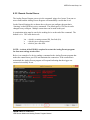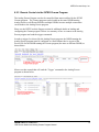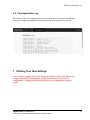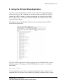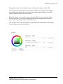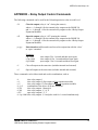
1
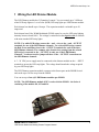
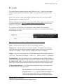
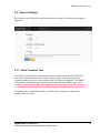
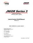
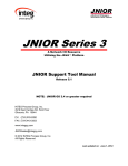
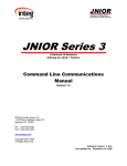
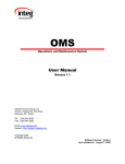
JNIOR Series 4 A Network I/O Resource Utilizing the JAVA Platform LED Dimmer Module And the Analog Presets Program Manual Release 3.0 NOTE: This version only works with the JNIOR 410, 412, 414 INTEG Process Group, Inc. 2919 East Hardies Rd, First Floor Gibsonia, PA 15044 PH (724) 933-9350 FAX (724) 443-3553 www.integpg.com [email protected] © 2015 INTEG Process Group, Inc. All Rights Reserved Last updated on: September 4, 2015 INTEG Process Group, Inc. TABLE OF CONTENTS 1 2 3 4 5 6 Wiring the LED Dimmer Module ............................................................................... 3 Using the JNIOR Web Page to Control the LED Dimmer Module ............................ 4 What is the Analog Presets Program? ......................................................................... 5 The Purpose of the Analog Presets Program .............................................................. 5 Installing the Analog Presets Program ........................................................................ 5 Configuring the Analog Presets Program ................................................................... 6 6.1 Levels ................................................................................................................... 8 6.2 General Settings ................................................................................................. 10 6.2.1 Global Transition Time ............................................................................... 10 6.2.2 Remote Control Server ............................................................................... 11 6.2.3 Remote Control via the INTEG Cinema Program ...................................... 12 6.3 View Application Log ........................................................................................ 13 7 Utilizing Your New Settings ..................................................................................... 13 8 Using the JR Color Wheel Application .................................................................... 14 APPENDIX – Relay Output Control Commands ............................................................. 16 JNIOR A Network I/O Resource LED Dimmer Module and Analog Presets Program Manual 2 INTEG Process Group, Inc. 1 Wiring the LED Dimmer Module The LED Dimmer module has 3 Channels of control. You can control up to 3 different white LED strip lights or 1 set of color (RGB) LED strip lights per LED Dimmer module. Each channel can handle up to 10 amps. The expansion module can handle up to 30 amps total. Each channel uses Pulse Width Modulated (PWM) control to vary the LED strip lighting intensity between 0 and 100%. The voltage is controlled on the negative side to conform with most standard LED strip lights. NOTE: For white LED strips, connect the + and – wires to the + and – OUTPUT terminals for one of the LED Dimmer channels. For colored LED strips, connect the Red, Green and Blue wires to the – OUTPUT terminals for each of the three LED Dimmer channels. The common wire (fourth wire) coming from the colored LED strip is connected to the + OUTPUT on only one of the LED Dimmer Channels. You do not need to jumper all three of the + OUTPUT connections on the LED Dimmer channels. A 5 – 24 VDC power supply must be connected to the dimmer module on the + - INPUT terminals to power the LED strip lights. The voltage should match the voltage required by your LED strip lights. The LED Dimmer expansion module connects to the Sensor port on the JNIOR Series 4 and can be up to 50 feet away from the JNIOR. You can use up to four (4) LED Dimmer modules per JNIOR. NOTE: The LED Dimmer module ONLY works with the JNIOR – the Series 4 consisting of the models 410, 412 and 414. JNIOR A Network I/O Resource LED Dimmer Module and Analog Presets Program Manual 3 INTEG Process Group, Inc. 2 Using the JNIOR Web Page to Control the LED Dimmer Module You can manually set the desired output for each channel of the LED Dimmer module using the JNIOR Configuration web page. This web page is launched from the JNIOR Support Tool – Beacon tab or by typing the JNIOR IP address and then /configure For example: http://10.0.0.201/configure After the web page is loaded, go to the I/O Control and then External tab. One to four LED modules will be displayed as shown below. The LED Channels will be numbered 1-3 on the first module and then 4-6, 7-9 and 10-12 on the subsequent modules. The modules are numbered according to how they are discovered on initial boot. You can control an individual output setting by clicking on the Set button for the appropriate channel. You can control all 3 channels for 1 module by clicking on the button for the Set Block command as shown below. Set Block Pop-Up JNIOR A Network I/O Resource LED Dimmer Module and Analog Presets Program Manual 4 INTEG Process Group, Inc. 3 What is the Analog Presets Program? The Analog Presets program is a program that runs on the JNIOR that allows the user to implement multiple levels of analog control that can be sent to the analog output on the JNIOR analog expansion modules. The program works with the LED Dimmer module, the 0 – 10 VDC analog expansion module, and the 4 – 20 mA analog expansion module. It will work with up to four of the LED Dimmer modules and one or two of the other analog expansion modules per JNIOR. They can be the same type of module or different types. 4 The Purpose of the Analog Presets Program The Analog Presets Program is meant to be a stepped analog control solution with optional relay output control. It is a way to allow the user to define specific analog values to be sent to the JNIOR analog outputs whenever a ‘trigger’ occurs. The trigger can be a change in state of a digital input or relay output, or a ‘message’ can be sent from another device or the INTEG Cinema program to the Analog Presets program. The amount of time it takes to transition from the current analog level to the new analog level can be adjusted. 5 Installing the Analog Presets Program The Analog Presets Program is an add-on program. INTEG distributes the program via an Update Project that is used with the JNIOR Support Tool. The JNIOR Support Tool and Analog Presets Program Update Zip can both be downloaded from the INTEG website at the following: http://www.integpg.com/support/jnior/ NOTE: Please make sure you install the version for the Series 4 JNIOR. NOTE: The current version on the website may differ from what is shown here. JNIOR A Network I/O Resource LED Dimmer Module and Analog Presets Program Manual 5 INTEG Process Group, Inc. Please click on the Download and save the zip file. Do NOT unzip it. The JNIOR Support Tool will unzip it. Go to the Update Tab in the JNIOR Support Tool and select Open Project and then navigate to where you saved the zip file. The JNIOR Support Tool will unzip the update project and show you all the steps. When you run the Update Project, the project will load the software, set the program to run on boot and cause the JNIOR to reboot so the program is started. 6 Configuring the Analog Presets Program After the Analog Presets Program has been loaded on to the JNIOR and rebooted, the Analog Presets Program can be configured via the Analog Presets web page. NOTE: You must use a ‘modern browser’ which is defined as Internet Explorer 10 or greater, Google Chrome or Firefox for the Analog Presets web page. JNIOR A Network I/O Resource LED Dimmer Module and Analog Presets Program Manual 6 INTEG Process Group, Inc. To launch the Analog Presets web page, type the IP address of your JNIOR in your Web browser address line followed by /analogpresets An example is as follows: http://192.168.1.210/analogpresets When you launch the Analog Presets web page, you will be asked to log in. Please use the default JNIOR username (jnior) and password (jnior). The web page on the Levels tab looks as follows: JNIOR A Network I/O Resource LED Dimmer Module and Analog Presets Program Manual 7 INTEG Process Group, Inc. 6.1 Levels The Analog Presets Program can have many different ‘Levels’. Each level can contain multiple analog outputs to be controlled. Each Level contains unique settings for that Level. Each Level is given a unique name and this is the name that can be sent from another program or device to ‘trigger’ the Level. From the Analog Presets web page, click on the ADD LEVEL button at the bottom of the web page to add a level. The Level name cannot contain any spaces. Please use an underscore to separate words. As you mouse over each area to be configured, a help window will be displayed providing you with details on the information to be entered. An example is shown below for the Setting Level box. Data to be entered is as follows. Fields not being used can be left blank. Name – enter the name for the Level, but you can change it anytime Setting Level – enter the value to be set for the channel. The number ranges from 0 – 100% and can be for one channel or multiple channels where each value is separated by commas. For example, 20,0,50,10,30,40 would be the value for 6 channels. Trigger – the level can be triggered by a JNIOR digital input or relay output going from ‘off’ to ‘on’. The format, for example, is DIN1 or ROUT1 (where 1 = 1 through 8) Transition Time – this is the amount of time in milliseconds that the JNIOR will take to transition the channel settings from the current value to the new value in equal increments for THIS LEVEL ONLY. A zero (0) indicates an immediate transition to the new value. If the value is blank, then the Global Transition time under the General Settings is used. 4-20ma Output Channels – If a 4-20ma analog expansion module is not connected to the JNIOR, this box will be greyed out. Enter the channel(s) to be controlled separated by a comma Acceptable values: 1, 2, 3, 4 (if NOT USED leave blank or -1) 1 and 2 are the outputs on the first 4-20 expansion module 3 and 4 are the outputs on the second 4-20 expansion module JNIOR A Network I/O Resource LED Dimmer Module and Analog Presets Program Manual 8 INTEG Process Group, Inc. 10v Output Channels – If a 10 v analog expansion module is not connected to the JNIOR, this box will be greyed out. Enter the channel(s) to be controlled separated by a comma Acceptable values: 1, 2, 3, 4 (if NOT USED leave blank or -1) 1 and 2 are the outputs on the first 10 v expansion module 3 and 4 are the outputs on the second 10 v expansion module 3 Channel LED Output Channels – If a 3 Channel LED expansion module is not connected to the JNIOR, this box will be greyed out. Enter the channel(s) to be controlled separated by a comma Acceptable values: 1 to 12 (if NOT USED leave blank or -1) 1, 2 and 3 are the outputs on the 1st LED Dimmer module 4, 5 and 6 are the outputs on the 2nd LED Dimmer module 7, 8 and 9 are the outputs on the 3rd LED Dimmer module 10, 11 and 12 are the outputs on the 4th LED Dimmer module Start Relay Output Action – a relay output (or multiple relay outputs) to be controlled when the level transition STARTs. End Relay Output Action – a relay output (or multiple relay outputs) to be controlled when the level transition ENDs. Example Relay Output Actions Action(s) can be entered for one or more relay outputs Acceptable values: See Appendix A For example, a value of c1 would close output 1 A value of o1 would open output 1 A value of c1p=1000 would pulse closed output 1 for 1 second The buttons at the bottom of the web page are used to Save your changes, Cancel your changes, Add a Level, Remove a Level or Test the level (after you have saved your changes). Please note that your changes take effect immediately after you save them. You do NOT have to reboot the JNIOR for the changes to take effect. JNIOR A Network I/O Resource LED Dimmer Module and Analog Presets Program Manual 9 INTEG Process Group, Inc. 6.2 General Settings By clicking on the General tab at the Analog Presets web page, the following web page is displayed. 6.2.1 Global Transition Time The Global Transition Time is the amount of time, in milliseconds, that the JNIOR will take to make the transition from the current ‘analog output’ value being used by the expansion module to the new value defined in the Level that was triggered. The JNIOR will make this transition in steps of approximately equal amounts until the new value is reached. The Global Transition Time applies to all ‘levels’ unless a specific Level has a transition time defined that will override the global transition time for that Level. The default value is 5000 milliseconds (5 seconds) and a 0 indicates an immediate sending of the new value JNIOR A Network I/O Resource LED Dimmer Module and Analog Presets Program Manual 10 INTEG Process Group, Inc. 6.2.2 Remote Control Server The Analog Presets Program can receive the command ‘trigger level_name’ from one or more clients and the Analog Presets Program will immediately execute that Level. On the General Settings tab, as shown above, the user can configure the port that is ‘listening’ on the JNIOR to receive commands. The default port is 9700, but it can be changed to any valid port. Multiple connections can be made to this port. A termination string must be sent by the sending device at the end of the command. The default is \r\n The valid choices are: \r\n - which is a carriage return (0D), line feed (0A) \r - which is just a carriage return \n - which is just a line feed NOTE: A reboot of the JNIOR is required to restart the Analog Presets program for these new settings to take effect. Below is an example of a device sending a command to the Analog Presests program that makes the connection to port 9700 and maintains the connection. If the connection is maintained, the Analog Presets program will respond indicating that the trigger was executed successfully or not. JNIOR A Network I/O Resource LED Dimmer Module and Analog Presets Program Manual 11 INTEG Process Group, Inc. 6.2.3 Remote Control via the INTEG Cinema Program The Analog Presets Program can also be controlled from macros utilized by the INTEG Cinema program. The Cinema program can be loaded on the same JNIOR running Analog Presets or a different JNIOR or multiple JNIORs because multiple connections can be made to the Analog Presets program. Please see the INTEG website Support section for additional details on loading and configuring the Cinema program. Below is a summary of how to connect to the Analog Presets program and send the trigger commands. In order to trigger Levels used by the Analog Presets program, the JNIOR running the Analog Presets program must be configured as a Raw Ethernet device as part of the Devices file for the JNIOR running the Cinema program (the same or different JNIOR) as shown below. Macros are then created that will send the ‘Trigger’ command to the Analog Presets program as shown below. JNIOR A Network I/O Resource LED Dimmer Module and Analog Presets Program Manual 12 INTEG Process Group, Inc. 6.3 View Application Log By clicking on the View Application tab on the Analog Presets web page, the following web page is displayed showing the information stored in the analogpresets.log file. 7 Utilizing Your New Settings After you have changed any of your settings and clicked on the SAVE button, the changes will take effect immediately except for the Remote Control Server configuration. Changes to the Remote Control Server configuration require a reboot. JNIOR A Network I/O Resource LED Dimmer Module and Analog Presets Program Manual 13 INTEG Process Group, Inc. 8 Using the JR Color Wheel Application In order to control the LED Dimmer module with colored LED strip lights (RGB), you will need to set each of the 3 channels to a certain percentage to get that color. INTEG currently has a BETA version of a software program that can be loaded on the JNIOR Series 4 that provides a ‘color wheel’ that will change the color and tell you the values you need for each channel. The Update project to load the JR Color Wheel can be downloaded from the INTEG website and is shown below. The JR Color Wheel application contains a web page that can be launched after you have loaded the program. Please type your JNIOR IP address then /jrcolor An example is shown below. http://10.0.0.67/jrcolor To use the application, just ‘click’ on any location on the wheel. If you ‘drag’ the circle around the wheel, it may take a few seconds for the JNIOR to catch up to where you stop. JNIOR A Network I/O Resource LED Dimmer Module and Analog Presets Program Manual 14 INTEG Process Group, Inc. Dragging the smaller circle within the square will change the intensity of the LED. The screen picture below shows the color wheel, slider bars to change the value output to each channel, the standard color value and the percentage output needed for each LED Dimmer channel to achieve the desired color. Below the color is a box that allows you to enter the HEX value for a color and click on the Set Color button. You can also change the time it takes to transition from color to color as you select different color values on the wheel. You can add a Level to the Analog Presets program that will send the three needed output values to achieve the desired color value. JNIOR A Network I/O Resource LED Dimmer Module and Analog Presets Program Manual 15 INTEG Process Group, Inc. APPENDIX – Relay Output Control Commands The following commands can be used for the RelayOutputAction value in each Level. cX Close the output (relay is “on” closing the contact) where x = 1 through 8 for the internal relay outputs on the JNIOR 310 and x = +1 through +8 for the external relay outputs on the 4 Relay Output Expansion Modules oX Open the output (relay is “off” opening the contact) where x = 1 through 8 for the internal relay outputs on the JNIOR 310 and x = +1 through +8 for the external relay outputs on the 4 Relay Output Expansion Modules p=yyy Pulse duration (milliseconds) and is used in conjunction with the ‘close’ or ‘open’ command Examples: c2p=1000 c+2p=1000 o3p=10000 close output 2 for 1 second and then open again close output 10 for 1 second and then open again open output 3 for 10 seconds and then close again c* Close all outputs at the same time (includes internal and external) o* Open all outputs at the same time (includes internal and external) These commands can be abbreviated and used in combination, such as: c1 close relay output 1 c+1 close relay output 9 (first output on first expansion module) c+5 close relay output 13 (first output on second expansion module) c1+1+5 combination of the above all in one command c1234 close relay outputs 1 through 4 c1368 close relay outputs 1, 3, 6, 8 o125 open relay outputs 1, 2, 5 c1+1p=1000 close relay outputs 1, 9 and pulse each for 1 second simultaneously JNIOR A Network I/O Resource LED Dimmer Module and Analog Presets Program Manual 16 INTEG Process Group, Inc. Summary Thank you for purchasing the JNIOR. Hopefully this manual made the getting-to-know process of your new JNIOR very quick and easy. The JNIOR has many more wonderful tools and features available, and are explained in detail in the supplied documents. Copyright Copyright 2015 INTEG Process Group, Inc. All rights reserved. Notice Every effort was made to make this manual as accurate and useful as practical at the time of the writing of this manual. However, all information is subject to change. Trademarks Trademarks are the property of their respective holders. Java is a trademark or registered trademark of Oracle (Sun Microsystems, Inc.) in the United States and other countries. Microsoft, Windows, MS-DOS and Internet Explorer are registered trademarks of Microsoft Corporation. Use Restrictions This User’s Manual and the software contained in the JNIOR are copyrighted by INTEG Process Group, Inc. and may not be copied or reproduced without prior consent from INTEG Process Group, Inc. INTEG Process Group, Inc. is not responsible for any errors or omissions that may be contained in this manual. Please do not hesitate to contact our JNIOR team at INTEG Process Group, Inc. We can be reached via phone, fax or e-mail as follows: INTEG Process Group, Inc. 2919 E. Hardies Road 1st Floor Gibsonia, PA 15044 www.integpg.com [email protected] PH (724) 933-9350 extension 20 FAX (724) 443-3553 JNIOR A Network I/O Resource LED Dimmer Module and Analog Presets Program Manual 17