1
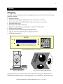
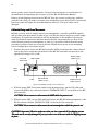
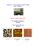
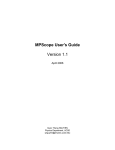
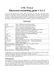
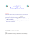
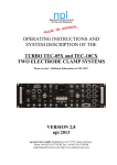
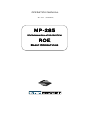
OPERATION MANUAL Rev. 3.07 ( 20080204) MPMP-285 Micromanipulator System ROE Basic Operations MPMP-285 Micromanipulator System Operation Manual ROE Basic Operations (Rev. 3.07 (20080204)) Sutter Instrument Company One Digital Drive Novato, CA 94949 Voice: 415-883-0128 Web: www.sutter.com Fax: 415-883-0572 Email: [email protected] II Copyright © 2008 Sutter Instrument Company. All Rights Reserved. MP-285 OPERATION MANUAL: ROE BASIC OPERATIONS – REV. 3.07 (20080204) III TABLE OF CONTENTS 1. GENERAL INFORMATION.................................................................................................................................................1 1.1 STRUCTURE OF THE MP-285 DOCUMENTATION PACKAGE............................................................................................................1 1.2 TECHNICAL SUPPORT ............................................................................................................................................................1 2. SETUP ........................................................................................................................................................................................3 2.1 UNPACKING ...........................................................................................................................................................................3 2.2 INITIAL SETUP AND GROSS MOVEMENT...............................................................................................................................4 2.3 INSTALLATION OF THE MP-285 MICROMANIPULATOR ON YOUR MICROSCOPE.................................................................6 2.3.1 General Considerations................................................................................................................................................6 2.3.2 Specifics .........................................................................................................................................................................6 2.4 MOUNTING HEADSTAGES .....................................................................................................................................................7 2.5 ADJUSTING THE ROTATING DOVETAIL BASE .......................................................................................................................8 2.6 MINIMIZING ELECTRICAL NOISE ..........................................................................................................................................9 3. MICROSCOPIC MANIPULATION..................................................................................................................................11 3.1 SOME BASIC INFORMATION ................................................................................................................................................11 3.2 SETUP SELECTION .............................................................................................................................................................11 3.3 CHANGING MINIMAL RESOLUTION ....................................................................................................................................12 4. PULSE MOVEMENT ...........................................................................................................................................................15 5. HOME FUNCTION...............................................................................................................................................................17 5.1 HOW TO DEFINE A NEW HOME ...........................................................................................................................................17 5.2 MOVING TO THE NEW HOME: .............................................................................................................................................17 5.3 PRACTICAL USE OF THE HOME FUNCTION .........................................................................................................................17 6. GENERALIZED ROBOTIC MOVEMENTS ..................................................................................................................19 6.1 SETTING ABSOLUTE ZERO ..................................................................................................................................................19 6.2 REDEFINING HOME ..............................................................................................................................................................19 6.3 CLEARING PROGRAM LOCATION #1 FOR RECORDING A NEW ROBOTIC SERIES ..............................................................19 6.4 TEACHING THE MP-285 CONTROLLER A NEW ROBOTIC SERIES ......................................................................................20 6.5 EXECUTING THE NEWLY ENTERED PROGRAM!..................................................................................................................21 6.6 LOADING A SAVED PROGRAM ............................................................................................................................................22 7. DIAGONAL OR 4TH AXIS MOVEMENTS....................................................................................................................23 8. ROE RESPONSE CHARACTERISTICS .........................................................................................................................25 8.1 CONTROLLING ROE KNOB TO MANIPULATOR STEPPER MOTOR AXIS ASSIGNMENT .....................................................25 8.2 CONTROLLING MOVEMENT AMOUNT PER ROE TURN .....................................................................................................25 INDEX ..........................................................................................................................................................................................27 MP-285 OPERATION MANUAL: ROE BASIC OPERATIONS – REV. 3.07 (20080204) 1 1. GENERAL INFORMATION 1.1 Structure of the MPMP-285 Documentation Package The MP-285 is a highly versatile stepper motor driven micromanipulator. Because of this versatility, the documentation necessary to cover various functions has rapidly grown to a size best described as unwieldy and thus has generally not been useful to most operators. In order to produce a more useful set of instructions, we have split the manual into two parts. The first part, “Basic Operations”, has been kept short and covers major functions with the aim of quickly guiding the first time user through the setup and use of the MP-285 for micromanipulation with emphasis on using the ROE (Rotary Optical Encoder) for user control. These steps are, in many ways, identical to the steps performed any time one sets up an MP-285 for use at a microscope. Many users will find that no other manual is necessary. The second part, “Reference Manual”, provides in-depth coverage of the MP-285. It documents the precise keystrokes (menu navigation) necessary to access each MP-285 function. The Reference Manual also describes, in detail, how to alter MP-285 performance via add-on accessories, perform microcontroller robotic programming, and how to use the serial computer interface. 1.2 Technical Support Unlimited technical support is provided by Sutter Instrument Company at no charge to our customers. Our technical support staff is available between the hours of 8:00 AM and 5:00 PM (Pacific Time) at (415) 883883-0128. 0128 You may also E-mail your queries to [email protected]. [email protected] MP-285 OPERATION MANUAL: ROE BASIC OPERATIONS – REV. 3.07 (20080204) 3 2. SETUP 2.1 Unpacking Carefully remove all components from the shipping container. One of each of the following should be included: • • • • • • • • • • MP-285 controller MP-285 micromanipulator and D25 cable for connection to controller Rotary Optical Encoder (ROE) and D15 cable for connection to controller Controller power cord Serial port cable (DB9 connectors) Metal dovetail headstage mounting plate with plastic isolation plate Metal dovetail rod clamp 2.5mm hex wrench for removing the shipping screws 7/64 hex wrench for adjusting the rotating dovetail base MP-285 documentation MP-285 RESET POWER SUTTER INSTRUMENT CO. MADE IN U.S.A. Figure 2-1. MP-285 Controller (front panel). HOM DIA 0 3 1 13 4 4 3 3 1 1 1 3 4 31 3 01 1 3 4 Figure 2-2. Manipulator. NOR FIN COAR PULS CON Figure 2-3. Rotary Optical Encoder (ROE). You may have also received one or more accessories for mounting your MP-285 and/or modifying the headstage mount to the manipulator (i.e., rotating base, microscope stage MP-285 OPERATION MANUAL: ROE BASIC OPERATIONS – REV. 3.07 (20080204) 4 mount, gantry stand, dovetail extension). Setup of these accessories is covered either in documentation accompanying the accessory or in the MP-285 Reference Manual. Remove all six shipping screws from the MP-285. Save the screws, warning tags, and hex wrench in the event you need to transport your manipulator in the future. Once these screws have been removed, handle the micromanipulator with care. The drive cables can be damaged 2.2 Initial Setup and Gross Movement Initially, you may want to simply connect your manipulator, controller, and ROE together and try some gross movements in order to get a feel for the controls and how to make simple movements. It is perfectly acceptable to set the manipulator in the middle of a bench top, make all electrical connections and then observe the unit’s movement by eye. Even if you wish to directly install your manipulator in your rig, it is useful to follow the initial setup procedure in order to learn how to move the unit and allow easy access to the mounting screws if subjected to unnecessary strain. 1. Connect the power cord to the MP-285 controller. Make certain that the voltage selector next to the power cord socket on the back of the MP-285 controller has been set to the appropriate voltage (110 or 220). VOLTAGE SELECTOR SERIAL PORT CABLE (9 pin) LINE POWER SUTTER INSTRUMENT FUSE LABEL 51 Digital Drive NOVATO, CA 94949 USA (415) 883 - 0128 SERIAL PORT 110 220 MODEL FUSE COMMAND INPUT VOLTS Hz 1 2 3 4 5 6 7 MANIPULATOR 8 1 DANGER 9 10 11 12 13 14 3 2 5 4 6 8 7 9 10 11 12 13 15 HIGH VOLTAGE 14 15 16 17 18 19 20 21 22 23 24 25 DISCONNECT POWER BEFORE OPENING UNIT! FUSE INPUT DEVICE CABLE (15 pin) MANIPULATOR CABLE (25 pin) Figure 2-4. MP-285 controller rear connections. 2. With the power OFF (front panel switch in the down position), use the D15 cable and connect the ROE to the connection labeled “COMMAND INPUT” on the back of the MP285 controller. CAUTION: Never connect or disconnect the ROE while the power is on! 3. With the power OFF, use the D25 cable and connect the MP-285 micromanipulator to the DB 25 connector labeled “MANIPULATOR” on the back of the controller. CAUTION: Never connect or disconnect the micromanipulator micromanipulator while the power is on! CAUTION: Important! Check to make sure that you have removed all six shipping screws. The unit can be severely damaged if you try to move one of the axes with the shipping screws in place. MP-285 OPERATION MANUAL: ROE BASIC OPERATIONS – REV. 3.07 (20080204) 5 To observe movement of the manipulator do the following: 1. Turn the power ON (front panel switch up). Observe the startup screen: S 1 *** MP-285 Controller *** P 1 Press MOVE, PRGM or select mag. with * 4. Press the <MOVE> key on the MP-285 controller keypad. Observe the movement screen: - 10789.20 - 10750.40 um um X Z - 10778.24 um Y 0 . 2 0 um Res. Assuming this was the initial power on from the unit after unpacking, you should have coordinates similar to those above (-10,000µm to -12,000µm). These coordinates correspond to the locations of the shipping screws. Turn a knob on the ROE. You should see one of the axes on the manipulator move and the coordinates on the screen of the controller change. The coordinates indicate how far you have moved in micrometers along each of the three axes. Before the unit was shipped from Sutter, its absolute origin (location 0,0,0) was set at the center of travel of each axis. This same location was also defined as “Home”. This means that you can make the manipulator move to the center of travel by a simple move to “Home”, as follows: 1. Make sure you are still in the movement screen (coordinates displayed). 2. Press the button on the ROE marked <HOME>. Observe the “rapid” movement of the manipulator to the center of travel of each axis. The controller display will read, “Going home” during the move, and will display coordinates close to 0,0,0 after the move is complete. The MP-285 controller front panel is configured with three colored LEDs. When lit, these LEDs indicate that a signal is being received from the input device. Each LED (yellow, red, and green) indicates input originating from one of the three knobs on the ROE (top, left, and right, respectively). MP-285 OPERATION MANUAL: ROE BASIC OPERATIONS – REV. 3.07 (20080204) 6 2.3 Installation of the MPMP-285 Micromanipulator Micromanipulator on your Microscope 2.3.1 General Considerations In most applications, it is best to try to mount the MP-285 in a location that allows for the widest range of movement. Usually, this means mounting so that the device is in the center of travel when it is in its normal operating position. To facilitate this procedure, move the manipulator to its center of travel before determining where it should be mounted. The base of the MP 285 manipulator is also the mounting surface for the bearing ways of the X-axis. When the base plate is pressed firmly against most mounting surfaces, torsional stress can be transmitted to the base and thus misaligns the bearing ways. A supply of four precision-thickness washers is included with your MP-285 manipulator. To limit misalignment, you should use one on each of the four mounting screws between the MP-285 manipulator base and your mounting surface. When mounting the MP-285 there should be no physical impediments to the full excursion of the three axes. Pay particular attention to the screws or clamps used to secure the base of the micromanipulator to make certain that the X-axis slide can move to the end of its travel without obstruction. Additional mounting considerations, as well as instructions pertaining to specific mounting accessories can be found in the Reference Manual. 2.3.2 Specifics The base of the MP-285 manipulator has four mounting holes on 2.5” centers. A template, drawn to scale and based on the footprint shown below, can be used to drill holes in a suitable mounting surface. 2.75” 2.75” 3.8125” 2.5” 2.5” Figure 2-5. Manipulator base dimensions. MP-285 OPERATION MANUAL: ROE BASIC OPERATIONS – REV. 3.07 (20080204) 2.25” 7 This four-hole pattern is also compatible with the MP-285 rotary base, part #285RBI and the mounting adapter plate, # 285210 (see the Reference Manual for further instructions). While it is possible to insert and tighten all four mounting screws with the MP-285 in one position, you may find it convenient to connect and power up the manipulator and position the X-axis for the best access to the screw holes. 2.4 Mounting Headstages The most stable way to mount a headstage is to fasten it directly to the Z-axis slide. The mounting hardware included with the MP-285 is designed to eliminate the need for custom machining of headstage and pipette holders. For example, Axon Instruments’ new 203B headstage mounts directly to the rotating dovetail on the MP-285 Z-axis. Other headstages require use of the dovetail mounting plate: A C C D C dovetail mounting plate: 2 middle (D) holes EPC: 1-1/16" x 2-7/32" (2 holes, A & B) D B CV-4: 1-1/8" x 1-15/16" (4 holes, B & C) Figure 2-6. Headstage mounting plate. The plastic portion of the plate provides electrical isolation while allowing for a direct mount of Axon Instruments’ CV-4 headstage or Heka Electronics’ EPC-7, 8, or 9 headstages. The user can drill additional holes to allow the plate-mount installation of other headstages. Headstage mounting instructions can be found in the Reference Manual. Whether using the Axon 203B Headstage or another headstage mounted on the dovetail mounting plate, the respective male dovetail is inserted into the female dovetail on the MP285 Z-axis. Slide the dovetail mounting plate/headstage assembly into the rotating-dovetail base and secure it by tightening the dovetail clamp set screw with a Phillips-head screwdriver. MP-285 OPERATION MANUAL: ROE BASIC OPERATIONS – REV. 3.07 (20080204) 8 Dovetail clamp set screw mounting Dovetail plate Plastic isolation plate Headstag e Rotating dovetail Figure 2-7. Mounting the headstage on the manipulator's Z-axis. 2.5 Adjusting the Rotating Dovetail Base The rotating dovetail base allows the pipette holder or headstage to be rotated and firmly fixed at any angle desired by the experimenter as required for access to a particular microscope. Loosen then retighten Rotate 0 15 15 30 30 45 45 30 30 15 15 Headstage 15 15 30 30 45 45 30 30 15 0 15 Figure 2-8. Adjusting the headstage angle. To adjust the rotary dovetail to your desired angle: 1. Loosen the brake set screw to rotate the headstage or pipette holder. Failure to loosen the screw may lead to rapid deterioration of the brake and rotating disk thereby reducing the ability to firmly secure the rotating dovetail. 2. Once you have determined the proper angle, firmly tighten the brake set screw to assure stable positioning of the rotating dovetail. It is not recommended that you use this rotational joint as a means of pipette replacement. Repeated repositioning of the rotary disk and brake will lead to rapid deterioration of the joint which may then not tighten properly to allow stable positioning of a pipette. MP-285 OPERATION MANUAL: ROE BASIC OPERATIONS – REV. 3.07 (20080204) 9 2.6 Minimizing Electrical Noise We are aware of two potential noise sources for users coupling their MP-285 with high-gain, high input impedance, electrophysiological recording amplifiers. The first is associated with the manipulator and its connecting cable from the controller. Under certain circumstances these may act as an antenna concentrating electric field noise that originates from nearby electrical equipment (computer monitors and fluorescent lights are the most notorious offenders) and bringing it into close proximity with recording apparatus. Grounding the manipulator will largely eliminate this noise source. Ground tabs are located on each motor housing for this purpose. It should be noted that the manipulator produces negligible electrical noise when it is not moving because it is powered by a linear power supply with no AC current present. The second potential source of noise is associated with the magnetic field radiated from the power supply transformer in the controller. Certain electrophysiological amplifiers are more susceptible to generating noise when exposed to this magnetic field. This noise can be minimized or eliminated by allowing a maximal distance between your MP-285 controller and your amplifier. It may be possible to decrease this noise source further by placing a soft steel plate or a piece of high permeability metal between the controller and the amplifier. MP-285 OPERATION MANUAL: ROE BASIC OPERATIONS – REV. 3.07 (20080204) 11 3. MICROSCOPIC MANIPULA TION 3.1 Some Basic Information Assuming you have already tried gross movement of the MP-285 as outlined above (Initial Setup and Gross Movement) then you have an understanding of most of the features necessary for microscopic manipulation using your MP-285. The controller makes two changes to implement fine movement: • • The number of microsteps commanded per revolution of the ROE is reduced. The size of the microsteps produced by the stepping motor (minimal resolution) is reduced from 0.2mm to 0.04mm. These two changes give you a wide range of control over the amount of movement commanded by a single turn of an ROE knob. In the gross movement mode, you are commanding slightly over 700mm/turn. In the precise movement mode, you can command as few as 20mm/turn. As with the other portions of this User’s Manual, it is hoped that enough information has been provided to get the average user “micromanipulating” with a minimum of time spent covering unnecessary detail. If you find yourself needing additional detail on any of the items covered, please consult the appropriate topic in the Reference Manual. 3.2 SETUP Selection In order for the MP-285 to make precise movements and have a greater amount of control over the movement, you instruct the controller to produce fewer microsteps (the minimal increment of manipulator movement) per rotation of the ROE knobs. Using simple commands, you choose one of four different “Setups” that vary the number of microsteps per turn of the ROE knob over a range of 512 to 5120 per turn. The following steps outline how to use your MP-285 to manipulate a pipette into position in the field of view of your microscope. In doing so, you will learn how to switch from one setup to another. The same procedure can also be used as the final steps of manipulator setup and installation assuming the MP-285 is mounted on or near your microscope. 1. Turn on the manipulator power; while still in the main menu press <1>. This selects Setup 1 and allows for rapid positioning of the pipette in your microscopic field of view. The upper left-hand corner of the display should now read “S⇒1”. 2. Press <MOVE> to allow movement; remember that you cannot make movements unless you see the movement screen displayed 3. Focus the microscope to a height slightly above your preparation. 4. Using the X and Y-axes, move the pipette tip to a position above the middle of your field of view. In most cases, the first indication that the pipette is in the correct approximate location is an out-of-focus shadow. You may need to work at a lower microscopic power to visualize the tip. 5. Once you can see the shadow of the tip above your preparation, use the Z-axis control (top ROE knob) to move the pipette down into focus. If you focused above your preparation, you should not crash the pipette into your dish and/or preparation. MP-285 OPERATION MANUAL: ROE BASIC OPERATIONS – REV. 3.07 (20080204) 12 If these operations are part of your initial installation, your manipulator may not be mounted in a position to allow you to center the pipette tip in the microscope field of view. If this is true, you will have to stop and adjust the mounting location of the manipulator and/or the angle of approach of the pipette and/or the mounting of the headstage in the rotary dovetail. After repositioning, you will be able to bring the pipette to the correct working location. See the MP-285 Reference Manual for additional information on pipette positioning and Sutter accessories to aid in pipette access to different microscopes. NOTE: Once you can see the pipette in your field of view, you are ready ready for micromanipulation. 1. Press <ESC> to get to the main menu 2. Press <4> to select Setup 4; the upper left hand corner of the display should now read S⇒4. 3. Press <MOVE> to return to the movement screen. 4. Rotate the knobs on the ROE and observe the precise control you have over the movement of the pipette. If you wish to have even better control, press the <COARSE/FINE> button on the ROE (see below) Four factory-installed Setups are selected from the main menu by pressing the corresponding number (1 through 4) from the MP-285 keypad. Assuming you are in the movement screen and you want to change the current Setup, the key sequence is as follows: 1. From the movement screen press <ESC> to access the main menu 2. Press the number key <1> through <4> corresponding to the Setup you wish to use. The actual values for number of microsteps per ROE turn are as follows: Table 3-1. Microsteps per ROE turn settings. Setup Number Microsteps per ROE turn 1 3694 2 5120 3 2560 4 512 3. Press <MOVE> to return to the movement screen and begin moving at the precision specified by the selected Setup. The selected setup is maintained when the MP-285 controller is turned off; you only need to select a different setup when you wish to change precision of movement. 3.3 Changing Minimal Resolution In addition to controlling the number of microsteps per ROE turn, you can also set the microstep size to one of two values (coarse=0.2µm or fine=0.04µm). You then have two different amounts of movement (ultimately two different precisions for each selected Setup). MP-285 OPERATION MANUAL: ROE BASIC OPERATIONS – REV. 3.07 (20080204) 13 To change resolution from one value to the other, simply press the <COARSE/FINE> button on the top of the ROE (coarse is up, fine is down). The movement screen also displays the resolution in the lower right corner “0.2 (or 0.04) µm Res”. Given a resolution in microns, we can now re-specify the amount of movement per ROE turn in microns for Setups 1 through 4: Table 3-2. Microns per ROE turn settings. Setup Number Microns per ROE turn at 0.2µ 0.2µm 0.04µ 0.04µm 1 716.8 143.36 2 1024 204.8 3 512 102.4 4 102.4 20.48 Thus, you have a relatively wide range of precision of movement. In practice, many users end up only using a very non-precise, fast moving setup (#1 or 2, coarse) for quickly positioning the pipette and then a precise setup (#4, fine) for micromanipulation under the microscope. You may find that none of these SETUPS delivers the type of responsiveness that you desire from the MP-285. The MP-285 Reference Manual provides complete instructions for defining and saving your own Setup. MP-285 OPERATION MANUAL: ROE BASIC OPERATIONS – REV. 3.07 (20080204) 15 4. PULSE MOVEMENT So far, all the movements you have made, whether gross movement that can be easily seen by eye or precise micro moves which can only be observed with the aid of a microscope, have been in Continuous movement mode. The MP-285 controller is also capable of commanding the micromanipulator to move in pulses, where both the length and speed of the individual pulse is controlled. You might wish to use pulse movement mode in order to move a pipette towards a target in quantized steps. Pulse mode has also been used as a means of final approach to a cell membrane during “giga-seal” formation. Intracellular electrophysiologists may find that a pulse approach at maximal speed (about 2.9mm/sec) may provide sufficient impulse to impale some types of cells. To change from continuous to pulse movement mode when using an ROE is quite simple. Just locate and press the <CONT/PULSE> button on the ROE. The controller is in Pulse mode when the button is depressed. The movement screen will also indicate Pulse mode movement by display of the word “Pulses” in the upper right corner. If no word is displayed, the unit is in continuous mode. Pulse movement can be most easily observed under a microscope. If you have already configured your microscope for micromanipulation as detailed in section “Microscopic Manipulation” then simply follow these steps: 1. From the main menu press <3> to access a Setup with medium size pulses. Note that each Setup defines a Pulse size. The size of the pulses is given in the table below. 2. Press <MOVE> to enter the movement screen 3. Depress the < CONT/PULSE > button on the ROE so that it is in the down position 4. Make sure the controller is set for coarse resolution microsteps (0.2 mm, ROE <COARSE/FINE> button up) 5. Now turn the ROE knob while observing pipette movement under the microscope. You should see movement in pulses of 10mm. The ROE produces eight pulses per turn when in pulse mode. Thus, each full turn will produce a total movement of 80mm in eight 10mm pulses. The speed of the movement is 1mm/second. While only four factory installed Setups were described above, there are actually six: five and six are identical to four with respect to the number of microsteps per ROE turn in continuous mode movement (described above). They do differ in the size of pulses used in Pulse movement mode. The following table lists the sizes of pulses for the six factoryinstalled setups in microsteps and micrometers as calculated for the two different microstep resolutions: MP-285 OPERATION MANUAL: ROE BASIC OPERATIONS – REV. 3.07 (20080204) 16 Table 4-1. Microsteps and microns per Pulse settings. Setup Number Microsteps per Pulse 1 Microns per Pulse at 0.2µ 0.2µm 0.04µ 0.04µm 20 4 0.8 2 10 2 0.4 3 5 1 0.2 4 2 0.4 0.08 5 1 0.2 0.04 6 25 5 1 The speed of pulse movement is 5000 microsteps/second for all Setups. As there are two different resolutions, this translates to the same two different speeds for each setup: 1 mm/second at coarse resolution and 200 mm/second at fine resolution. You may find that no SETUP delivers the size and or speed pulses that you desire. The reference manual gives complete instructions for defining pulse size and speed and saving defined values to a new setup. MP-285 OPERATION MANUAL: ROE BASIC OPERATIONS – REV. 3.07 (20080204) 17 5. HOME FUNCTION “Go home” is the simplest of the programmable robotic functions available on the MP-285. Using the home function, you can establish a point in space to which you can command the micromanipulator to return. You may have used the home function to quickly move the manipulator to the center of travel during the “Initial Setup” procedure. At the factory, the center of travel for all three axes is established as both the absolute zero and the location of “Home” but any location can be designated as “Home”. Once a new location is defined as “Home”, the MP-285 controller will automatically move back to that location by a simple press of the <HOME> button on the ROE. 5.1 How to Define a New Home 1. Press <MOVE> to access the movement screen 2. Move the manipulator to the desired home location 3. Press <*>. The Robotics Menu will appear: Home ▓ New Home Show home Execute Learn Select Program 4. Press <TAB> to move the cursor (indicated by the arrow) to “New Home”. Press <ENTR>, the New Home menu will appear: ▓ Accept new home (TAB to edit) spd = 2000 um/s res = .20 um/ Step 5. Press <ENTR> to accept the default speed and resolution. You will be back in the movement screen. 5.2 Moving to the New Home: The location you just selected is now the new home. 1. Use the ROE knobs to move away from the new home 2. Press the <HOME> button on the ROE 3. The controller will move back to the new home. 5.3 Practical Use of the Home Function Many users find the ability to move to a specified location useful for bringing a pipette back into the general area of the microscope’s field of view after installing a new pipette. Note that the accuracy of repositioning is very dependent on exactness of pipette length and installation into a holder. If you use the home function to reposition after pipette exchange, you may want to follow these guidelines: • • Define your home position as a location above the plane of focus of your preparation. Mark your pipette puller in such a way as to make pipettes of approximately the same length. MP-285 OPERATION MANUAL: ROE BASIC OPERATIONS – REV. 3.07 (20080204) 18 • • • Try to fabricate concentric pipettes. Try to install your pipettes in the holder such that they always extend the same amount. If you use a rotating device to position the manipulator, try to install it such that rotation is up against a hard stop when the manipulator is in the operating location. Note that you accepted the factory set speed and resolution for the move back to home. If you wish, you can define both; for example, you can make the move to home even faster. Details on how to specify speed and resolution are given in the MP-285 Reference Manual. MP-285 OPERATION MANUAL: ROE BASIC OPERATIONS – REV. 3.07 (20080204) 19 6. GENERALIZED ROBOTIC MOVEMENTS In addition to a simple movement like “Go Home”, the MP-285 is also capable of learning and remembering a complex series of Robotic movements. A series of recorded movements can be executed once or many times in a loop. The series of moves can also be executed in the reverse order in which they were recorded. The following section teaches you how to record and execute a series of robotic movements by demonstration. You will find it easy to use robotic movements to remove your pipette from the field of view to a location where you can easily switch in a new pipette. Such a function provides a complement to “Go Home”, used in the proceeding section, to robotically move a pipette from a distant location to the field of view. It is assumed that you have installed your micromanipulator at your microscope and are capable of bringing your pipette into focus in your field of view. If you have not yet done so, you may wish to proceed through the previous sections of this manual. 6.1 Setting Absolute Zero With your pipette centered at a location in the middle of the field of view of your microscope, you may find it advantageous to define this location as the absolute zero (0,0,0) for the MP285 controller. Once this is done, it is straightforward to know where you are when you are looking at the coordinate display on the controller. It is probably a good idea to define the zero as a location slightly above the surface of your preparation and/or specimen dish. This way you will be less likely to smash pipettes into your work. To set the absolute zero, do the following (from the movement screen): 1. 2. 3. 4. 5. 6. <ESC> to main menu and press <PRGM> <TAB> 2X to “SETUP” and press <ENTR> <ENTR> to access “AXES” menu <ENTR> to access “New Origin” <ENTR> 2X more to complete the reset <ESC> 3X back to main menu and press <MOVE> You should be back in the movement screen and the coordinates on the display should read 0.00mm. 6.2 Redefining Home If you also wish to set this location as your home location, you must redefine it as such: 1. 2. 3. 4. Press <*> then <TAB> to “New Home” Press <ENTR> to access “New Home” Press <ENTR> to accept the default speed and resolution. You will be back in the movement screen. 6.3 Clearing Program Location #1 for Recording a New Robotic Series Robotic movements are initially stored in program location #1. If there is another series already stored in this location that you wish to retain you must move it to another location first. When shipped, program location #1 is occupied by a test routine. While you probably MP-285 OPERATION MANUAL: ROE BASIC OPERATIONS – REV. 3.07 (20080204) 20 have no reason to save this routine, you may wish to save it to another location simply to learn the procedure for later reference. To move program #1 to a new location and free up location #1, follow these steps (from the movement screen): 1. 5. 6. 7. 8. Press <*> to enter the Robotics menu <TAB> 5X to “Select program” and press <ENTR> Press <ENTR> to accept “Save/Clear” <TAB> to a free location (for e.g. #7) and press <ENTR> <ESC> back to the movement screen Note that the original copy of program #1 is still in location 1 and will be overwritten when new robotic moves are entered. 6.4 Teaching the MPMP-285 Controller a New Robotic Series You are ready to teach the controller a series of movements to robotically move the manipulator to a location where pipette exchange is possible: 1. Press <ESC> to reach the main menu and press <1> to put the manipulator in Setup #1 for coarse movement, press <MOVE> to return to the movement screen 2. Press <*> to enter the Robotics menu. <TAB> 3X to “Learn” and press <ENTR> to gain access to Learn functions. You will be issued the following warning: WARNING: Program 1 contains vectors. Press ESC to quit or another to continue. 3. If you have already saved Program 1, or if you do not need to, then press any key other than <ESC> to continue to the following screen: Program 1: Add vectors after 6 -or-. Start new program 1 with vector no. 1 4. <TAB> to “Start new …” and press <ENTR> to access the main Learn mode menu: ▓ Add vector after Insert pause 0 End program Go home Delete 5. Press <ENTR> to add the first vector (actually the end point of the first move). You will enter a screen that <**>asks for the desired speed for the move. ▓ Accept new home (TAB to edit) spd = 2000 um/s res = .20 um/ Step 6. <TAB> to “spd”, press <ENTR>, and press <6550> to put in a speed of 6550mm/sec. This will make the manipulator move as fast as possible during robotic movement. MP-285 OPERATION MANUAL: ROE BASIC OPERATIONS – REV. 3.07 (20080204) 21 Now you should see a screen similar to the movement screen but with one exception, the <L L> in the lower right corner indicates that you are in “Learn mode”. You cannot leave this mode properly without formally ending your learned series of movements. 7. Now, move your manipulator to a location where you can most easily exchange your pipette. This will most likely, but not necessarily, involve moving the Z-axis to its maximal upward extension and the X-axis to its maximal rightward extension (for a right-side mount manipulator). You may also want to move the y-axis. 8. Press <*>, then press <ENTR> to add new vector 9. Press <*>, then <TAB> 1X to “End program” and press <ENTR> You may have a dish that requires a circuitous route for entry and exit. If this is true, you can easily define a multiple step route out of the dish by multiple cycles of steps one and two above to make a move and then record it by entering the new vector and then finally using step three to end the program. To store your newly entered routine in a location other than program location #1, follow the steps detailed in the section “Clear Program Location #1 for recording a new Robotic Series”. 6.5 Executing the Newly Entered Program! Presumably, you have just entered the Robotic Series described above. It can now be used to move your pipette effortlessly from your working location to a position where you can exchange for a new pipette. Note that if you have not just entered the new series in program location #1, you must first load the program location that contains the series. To do this, follow the instructions below under “Loading a Saved Program”. In order to observe the robotic movement, you must first bring the pipette back into the working location by the following command from the move screen: Press the <HOME> button on the ROE The controller screen will display the words “Going home” and the manipulator will methodically move the pipette back to your field of view. If you did not change the pipette while you recorded the robotic series, then the pipette tip should come back exactly to the location you defined as “Home” earlier. To use the Robotic series to move the pipette out for exchange follow these steps: 1. From the move screen, press <*> to enter the Robotics menu 2. <TAB> 2X to “Execute” and press <ENTR> to access the Execute menu: ▓ Do once Abs/Rel Loop Reverse Now: Absolute, Program 1 3. Press <ENTR> again to accept “Do once” The screen will display the words “Executing. To stop: press key & hold until end of move”. As the robotic moves were entered at the fastest possible speed (6550mm/sec) setting the move should appear significantly faster than the move to home above. If you wish, you can MP-285 OPERATION MANUAL: ROE BASIC OPERATIONS – REV. 3.07 (20080204) 22 change your move to home to the speed of 6550mm/sec from the default value of 2000mm/sec (home speed can be changed whenever you enter a new home). If you programmed a multiple step withdrawal pattern to move your pipette out through a circuitous route, you may want to use a similar pattern to move your pipette into the working area. This can be accomplished simply by executing the above robotic movement in reverse: 1. From the move screen, press <*> to enter the Robotics menu 2. <TAB> 2X to “Execute” and press <ENTR> 3. <TAB> 2X to “Reverse” and press <ENTR> to accept. The manipulator will position the pipette in the center of your field of view in the reverse order of the steps you used to move it out when you taught the controller this routine above. 6.6 Loading a Saved Program If the program you wish to run has been saved but is not currently loaded, perform the following steps: 1. 2. 3. 4. 5. Press <*> to enter the Robotics menu <TAB> 5X to “Select program” and press <ENTR> <TAB> to “Load” and press <ENTR> to accept <TAB> to a desired program and press <ENTR> <ESC> back to the movement screen MP-285 OPERATION MANUAL: ROE BASIC OPERATIONS – REV. 3.07 (20080204) 23 7. DIAGONAL OR 4TH AXIS MOVEMENTS By simultaneous movement of two axes, the MP-285 is able to produce movement in a synthetic fourth axis or diagonal. This feature allows for axial micropipette movement along an axis at an angle with respect to the coordinate system defined by the three axes (x, y, and z) of the manipulator. To make diagonal movements while in the movement screen: 1. Press the remote NORM/DIAG button on the encoder (down and lit = diagonal mode). 2. The movement screen should now indicate that the controller is in diagonal mode as evidenced by the word “Diagonal” in the lower middle of the screen. 3. Diagonal movement is accomplished by turning the Z-axis knob on the ROE. The controller is factory programmed to produce fourth axis movement in the X-Z plane at a 45-degree angle. Establishment of fourth axis movement at other angles or in other planes is covered in detail in the MP-285 Reference Manual. MP-285 OPERATION MANUAL: ROE BASIC OPERATIONS – REV. 3.07 (20080204) 25 8. ROE RESPONSE CHARACTERISTICS CHARACT ERISTICS The response characteristics of the ROE are fully adjustable. For purposes of simplicity, this manual indicates limited adjustment to the values preprogrammed in factory installed Setups. It is possible to further tailor ROE response to your usage. The following list outlines the part of the controller menu and the corresponding part of the MP-285 Reference Manual which deals with each adjustment. 8.1 Controlling ROE Knob to Manipulator Stepper Stepper Motor Axis Assignment The MP-285 software allows full control over which ROE knob is connected to each of the three physical axes of the manipulator. Furthermore, one can control the direction of movement commanded by a given input. Axes assignment is covered in the manual under Controller Configuration and is adjusted using the menu command [PRGM\Setup\Axes]. 8.2 Controlling Movement Amount Per ROE Turn How much and how fast the MP-285 manipulator moves in response to a single turn of the ROE knob is controlled by a single parameter for continuous movement and two parameters for pulse movement. These parameters are described in detail in the MP-285 Reference Manual under Controller Configuration and are adjusted using the menu command [PRGM\Continuous] for continuous movement and the command [PRGM\Pulse Mode] for pulse movement. A subset of these parameters can also be adjusted during movement using the menu command [MOVE\1,2,4 or 5] as described in the Movement Screen section of the MP-285 Reference Manual. MP-285 OPERATION MANUAL: ROE BASIC OPERATIONS – REV. 3.07 (20080204) 27 INDEX amount per ROE turn .................................................25 control of.....................................................................25 D diagonal or 4th axis movements .................................... 23 G P pulse movement ..............................................................15 general information ...........................................................1 generalized robotic movements ..................................... 19 R ROE response characteristics .........................................25 H home function................................................................. 17 S setup...................................................................................3 M microscopic manipulation.............................................. 11 movement T technical support ...............................................................1 MP-285 OPERATION MANUAL: ROE BASIC OPERATIONS – REV. 3.07 (20080204)