1
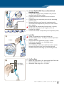
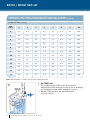
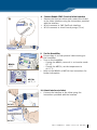
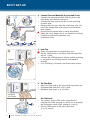
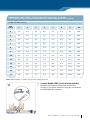
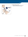
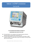
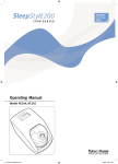
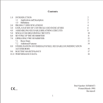
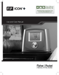
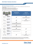
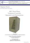
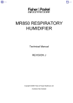
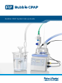
Bubble CPAP System Set-up Guide For full User Instructions, please refer to Bubble CPAP System User Instructions (BC151/BC161 PN 185042847 and BC171 PN 185042848). BC151 / BC161 BC161 (connects to F&P FlexiTrunk™ Interface) BC151 (connects to T-bar Interface) 10 9 8 7 6 5 Checks During Operation • Regularly observe that the water is feeding into the humidification chamber. • Should the water level exceed the maximum level marked on the humidification chamber, the chamber should be replaced. • Check that all connections are tight before use and after any adjustment. •Ensure air flow is present at all times. If air flow is interrupted, turn off the humidifier. • Regularly observe the circuit for condensate. Drain as required. • Regularly observe the CPAP generator for bubbling. If bubbling is not observed, check for and minimize air leaks in the system and at the patient. If air leaks have been minimized, air flow may be increased to achieve continuous bubbling. • Regularly observe the water level in the CPAP generator and overflow container. Refill the CPAP generator if the water level drops below the minimum water level line. Check and empty the overflow container once every 8 hours or as needed. • Monitor patient oxygen levels. • Always use pressure monitoring to verify that the patient is receiving the prescribed CPAP level. F & P bubb l e cpap s e t - up G ui d e 1 BC151 / BC161 SET-UP 1. Insert Humidification Chamber Discard the chamber if the seals are not intact when received. • Slide the chamber on to the humidifier base. • Remove the blue caps. 2. Connect Water Bag Hang the water bag, unwind the water feed set and spike the water bag. • Open the vent on the vented spike. • Check the humidification chamber for water flow from the bag. • If no water is visible in the chamber or water consumption is low, check that the bag is spiked properly and that the feed tube is not kinked or blocked. Try gently squeezing the bag to promote water flow. Ensure that the height of the water bag is at least higher than the humidification chamber. If in doubt replace the chamber. Discard the chamber if the water level exceeds the maximum water level line. 3. Fill Bubble CPAP Generator Water level too low • Using the fill-funnel provided, fill the CPAP generator with sterile water until water flows into the overflow container. • Set the CPAP probe to 10 cmH2O, ready for the leak test. Ensure that the fill-funnel remains on the Bubble CPAP generator. Ensure that the humidifier and Bubble CPAP generator are mounted below the patient. Water level correct 2 F & P bubb l e cpap s e t - up G ui d e 4. Connect Bubble CPAP Pressure Manifold and Breathing Circuit • Connect the oxygen tubing between the pressure manifold and the flow source. • Connect the pressure manifold to the chamber inlet port. • Connect the blue inspiratory tube to the remaining chamber port. • Remove the blue caps from the inspiratory tube and install the temperature probe ports and heaterwire adapter. Ensure that the heater-wire (inside tube) is evenly distributed along the circuit length and is not bunched or kinked. • Connect test elbow to expiratory and inspiratory limbs. 5. Leak Test Check all connections are tight before use. • Set the CPAP probe to 10 cmH2O and the input flow rate to 1 L/min. • Observe the CPAP generator. Gentle, audible bubbling is acceptable; no bubbling means unacceptable leakage. • If no bubbling is observed, check the entire system. Remove the correct port cap from the pressure manifold before connecting any monitoring device. 1 L/min 10 9 8 7 6 5 6. Set Flow Rate 6-8 L/min (<15 L/min) • Adjust the flow rate to the prescribed input flow rate. • Recommended flow rate: 6 to 8 L/min. • Allowable flow range: 4 to 15 L/min. F & P bubb l e cpap s e t - up G ui d e 3 BC151 / BC161 SET-UP Pressure-Flow Table – F&P Bubble CPAP Generator used with F&P Infant Interface, typical mean pressure values (cmH20) WITH NO LEAK Probe Setting (cmH2O) Flow (L/min) 3 4 5 6 7 8 9 10 4 3.1 4.1 5.1 6.1 7.1 8.1 9.1 10.0 5 3.2 4.2 5.3 6.3 7.3 8.3 9.2 10.1 6 3.4 4.4 5.4 6.4 7.4 8.4 9.3 10.2 7 3.6 4.6 5.6 6.6 7.6 8.5 9.5 10.4 8 3.8 4.8 5.8 6.8 7.8 8.7 9.6 10.5 9 4.0 5.0 6.0 7.0 7.9 8.9 9.8 10.6 10 4.3 5.3 6.2 7.2 8.1 9.0 9.9 10.8 11 4.6 5.6 6.5 7.4 8.4 9.2 10.1 10.9 12 4.9 5.8 6.8 7.7 8.5 9.4 10.2 11.1 13 5.2 6.1 7.0 7.9 8.8 9.6 10.4 11.3 14 5.5 6.4 7.3 8.2 9.0 9.8 10.6 11.4 15 5.8 6.7 7.5 8.4 9.2 10.0 10.8 11.6 Note: Other interfaces or circuits may produce varying pressures. 7. Set CPAP Level 10 9 8 7 6 •The number on the CPAP probe above the lid indicates the CPAP pressure in cmH2O. As an example, the illustration shows CPAP setting of 6 cmH2O. •Set the CPAP probe at the prescribed level (3 to 10 cmH2O). 4 F & P bubb l e cpap s e t - up G ui d e 8. Connect Bubble CPAP Circuit to Infant Interface • Remove the flow test elbow and connect the circuits to the Infant Interface using the instructions provided with the interface. • BC161 connects to F&P FlexiTrunk Interface. • BC151 connects to short binasal prongs (T-bar). 9. Set the Humidifier Ensure there is air flow present before turning on the humidifier. •Turn on the humidifier. –If using the MR850, ensure it is on Invasive mode (37 °C). –If using the MR730, set the temperature to 40 °C, -3. • Refer to the MR850 or MR730 User Instructions for further information. MR850: 37 °C MR730: 40 °C, -3 10.Attach Interface to Infant • Connect the interface to the infant using the instructions provided with the interface. BC161 BC151 F & P bubb l e cpap s e t - up G ui d e 5 BC171 BC171 (connects to Flow Driver) 10 9 8 7 6 5 Checks During Operation • Regularly observe that the water is feeding into the humidification chamber. • Should the water level exceed the maximum level marked on the humidification chamber, the chamber should be replaced. • Check all connections are tight before use and after any adjustment. •Ensure air flow is present at all times. If air flow is interrupted, turn off the humidifier. • Regularly observe the circuit for condensate. Drain as required. • Regularly observe the CPAP generator for bubbling. If bubbling is not observed, check for and minimize air leaks in the system and at the patient. If air leaks have been minimized, air flow may be increased to achieve continuous bubbling. • Regularly observe the water level in the CPAP generator and overflow container. Refill the CPAP generator if the water level drops below the minimum water level line. Check and empty the overflow container once every 8 hours or as needed. • Monitor patient oxygen levels. • Always use pressure monitoring to verify that the patient is receiving the prescribed CPAP level. 6 F & P bubb l e cpap s e t - up G ui d e BC171 SET-UP 1. Insert Humidification Chamber Discard the chamber if the seals are not intact when received. • Slide the chamber on to the humidifier base. • Remove the blue caps. 2. Connect Water Bag • Hang the water bag, unwind the water feed set and spike the water bag. • Open the vent on the vented spike. • Check the humidification chamber for water flow from the bag. • If no water is visible in the chamber or water consumption is low, check that the bag is spiked properly and that the feed tube is not kinked or blocked. Try gently squeezing the bag to promote water flow. Ensure that the height of the water bag is at least 50 cm higher than the humidification chamber. If in doubt replace the chamber. Discard the chamber if the water level exceeds the maximum water level line. 3. Fill Bubble CPAP Generator Water level too low • Using the fill-funnel provided, fill the CPAP generator with sterile water until water flows into the overflow container. • Set the CPAP probe to 10 cmH2O, ready for the leak test. Ensure that the fill-funnel remains on the Bubble CPAP generator. Ensure that the humidifier and Bubble CPAP generator are mounted below the patient. Water level correct F & P bubb l e cpap s e t - up G ui d e 7 BC171 SET-UP 4. Connect Pressure Manifold, Dry Line and Circuit • Connect the pressure manifold with dry line to the flow driver and chamber inlet port. • Connect the blue inspiratory limb to the remaining chamber port. • Remove the blue caps from the inspiratory tube and install the temperature probe ports and the heaterwire adapter. Ensure that the heater wire is evenly distributed along the circuit length and is not bunched or kinked. • Connect test elbow to expiratory and inspiratory limbs. 5. Leak Test 1 L/min Check all connections are tight before use. • Set the CPAP probe to 10 cmH2O and the input flow rate to 1 L/min. • Observe the CPAP generator. Gentle, audible bubbling is acceptable; no bubbling means unacceptable leakage. • If no bubbling is observed, check the entire system. 10 9 8 7 6 5 6. Set Flow Rate • Adjust the flow rate to the prescribed input flow rate. • Recommended flow rate: 6 to 8 L/min. • Allowable flow range: 4 to 15 L/min. 6-8 L/min (<15 L/min) 10 9 8 7 6 Set CPAP Level •The number on the CPAP probe above the lid indicates the CPAP pressure in cmH2O. As an example, the illustration shows CPAP setting of 6 cmH2O. • Set the CPAP probe at the prescribed level (3 to 10 cmH2O). 8 F & P bubb l e cpap s e t - up G ui d e Pressure-Flow Table – F&P Bubble CPAP Generator used with F&P Infant Interface, typical mean pressure values (cmH20) WITH NO LEAK Probe Setting (cmH2O) Flow (L/min) 3 4 5 6 7 8 9 10 4 3.1 4.1 5.1 6.1 7.1 8.1 9.1 10.0 5 3.2 4.2 5.3 6.3 7.3 8.3 9.2 10.1 6 3.4 4.4 5.4 6.4 7.4 8.4 9.3 10.2 7 3.6 4.6 5.6 6.6 7.6 8.5 9.5 10.4 8 3.8 4.8 5.8 6.8 7.8 8.7 9.6 10.5 9 4.0 5.0 6.0 7.0 7.9 8.9 9.8 10.6 10 4.3 5.3 6.2 7.2 8.1 9.0 9.9 10.8 11 4.6 5.6 6.5 7.4 8.4 9.2 10.1 10.9 12 4.9 5.8 6.8 7.7 8.5 9.4 10.2 11.1 13 5.2 6.1 7.0 7.9 8.8 9.6 10.4 11.3 14 5.5 6.4 7.3 8.2 9.0 9.8 10.6 11.4 15 5.8 6.7 7.5 8.4 9.2 10.0 10.8 11.6 Note: Other interfaces or circuits may produce varying pressures. 7. Connect Bubble CPAP Circuit to Infant Interface • Remove the flow test elbow and connect the circuits to the Infant Interface using the instructions provided with the interface. F & P bubb l e cpap s e t - up G ui d e 9 BC171 SET-UP 8. Connect Pressure Line to Flow Driver • Connect the pressure line filter end of the pressure line to the flow driver. • Connect the pressure line elbow connector end of the pressure line to the nasal tubing pressure port. 9. Set the Humidifier (MR850) Ensure there is air flow present before turning on the humidifier. •Turn on the flow driver. •Turn on the humidifier. –If using the MR850, ensure it is on Invasive mode (37 °C). • Refer to the MR850 User Instructions for further information. MR850: 37 °C A 9A.Set the Humidifier (MR730) Ensure there is air flow present before turning on the humidifier. •Turn on the flow driver. •Turn on the humidifier. –If using the MR730, set the temperature to 40 °C, -3. • Refer to the MR730 User Instructions for further information. MR730: 40 °C, -3 1 0 F & P bubb l e cpap s e t - up G ui d e 10.Attach Interface to Infant • Connect the interface to the infant using the instructions provided with the interface. BC171 F & P bubb l e cpap s e t - up G ui d e 1 1 For more information please contact your local Fisher & Paykel Healthcare representative Manufacturer Fisher & Paykel Healthcare Ltd 15 Maurice Paykel Place East Tamaki, Auckland 2013 PO Box 14 348, Panmure Auckland 1741 New Zealand Tel: +64 9 574 0100 Fax: +64 9 574 0158 Email: [email protected] Web: www.fphcare.com Australia Fisher & Paykel Healthcare Pty Limited 36-40 New Street, PO Box 167 Ringwood, Melbourne Victoria 3134, Australia Tel: +61 3 9879 5022 Fax:+61 3 9879 5232 Austria Tel: 0800 29 31 23 Fax: 0800 29 31 22 185034215 REVa EN © 2011 Fisher & Paykel Healthcare Limited Benelux Tel: +31 40 216 3555 Fax:+31 40 216 3554 Spain Tel: +34 902 013 346 Fax: +34 902 013 379 Sweden Tel: +46 8 564 76 680 Fax: +46 8 36 63 10 Switzerland Tel: 0800 83 47 63 Fax: 0800 83 47 54 Taiwan Tel: +886 2 8751 1739 Fax: +886 2 8751 5625 China Tel: +86 20 3205 3486 Fax:+86 20 3205 2132 Turkey Tel: +90 312 354 34 12 Fax: +90 312 354 31 01 France Tel: +33 1 6446 5201 Fax:+33 1 6446 5221 UK Fisher & Paykel Healthcare Ltd Unit 16, Cordwallis Park Clivemont Road, Maidenhead Berkshire SL6 7BU, UK Germany Tel: +49 7181 98599 0 Fax:+49 7181 98599 66 India Tel: +91 80 4284 4000 Fax:+91 80 4123 6044 Irish Republic Tel: 1800 409 011 www.fphcare.com Italy Tel: +39 06 7839 2939 Fax:+39 06 7814 7709 EC REP Tel: +44 1628 626 136 Fax: +44 1628 626 146 USA/Canada Tel: +1 800 446 3908 or +1 949 453 4000 Fax:+1 949 453 4001