1
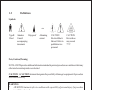
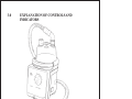
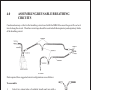
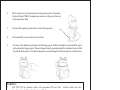
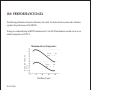
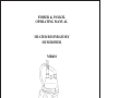
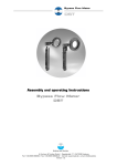
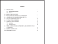
Contents
1.0
INTRODUCTION
1.1 Application and Description
1.2 Definitions
2.0 PRODUCT SPECIFICATIONS
3.0 EXPLANATION OF CONTROLS AND INDICATORS
4.0 ASSEMBLING REUSABLE BREATHING CIRCUITS
5.0 SINGLE USE BREATHING CIRCUITS
6.0 SETTING UP THE HUMIDIFIER
7.0 OPERATING THE HUMIDIFIER
7.1 Basic Steps
7.2 Additional Features
8.0 STERILISATION OF FISHER & PAYKEL REUSABLE HUMIDIFICATION
ACCESSORIES
9.0 ROUTINE MAINTENANCE
10.0 PERFORMANCE DATA
2
2
3
4
6
8
10
11
13
13
14
15
17
18
Part Number 185040653
Printed March 1998
Revision E
1
1.0
1.1
INTRODUCTION
Application and Description
The Fisher & Paykel MR410 Heated Respiratory Humidifier is designed to warm and add humidity to
gases delivered to patients requiring mechanical ventilation or other positive pressure breathing systems
where the gas flow remains at a constant level.
The warmth and moisture are supplied by passing the gas over the surface of heated water.
The heater plate is controlled to a constant temperature which is determined by the setting of the heater
control knob. The temperature of the gas delivered to the patient must be monitored independently.
2
1.2
Definitions
Symbols
~
I P X 1
Type B
Class 1
Attention:
Drip-proof
Consult
accompanying
documents
U L
Alternating
current
CAUTION
Electrical Shock
Hazard. Refer to
qualified service
personnel
CAUTION
Hot surfaces
may exceed
75°C
Note, Caution, Warning:
NOTE: A NOTE provides additional information intended to point out procedures or conditions which may
otherwise be misinterpreted or overlooked.
CAUTION : A CAUTION statement designates the possibility of damage to equipment if a procedure
is not followed exactly.
WARNING
*
A WARNING statement refers to conditions with a possibility of personal injury if a procedure
is not followed exactly.
3
2.0
PRODUCT SPECIFICATIONS
Dimensions :
135mm x 170mm x 156mm (without chamber fitted)
Weight:
1.3kg (without chamber fitted)
1.6kg (with chamber fitted and filled with water)
Electrical Rating
Supply Frequency:
50 - 60 Hz
Supply Voltage:
230V +/- 25V
(As specified on unit) 115V +/- 12V
100V +/- 10V
Water Heater:
Capacity
Supply Current:
0.4A max at 230V
0.8A max at 115V
0.9A max at 100V
85W
Maximum Operating
Pressure:
20 kPa
Heater Control:
Range:
Settings of 1 - 9 (Corresponds to heater plate temperature of 45 - 75°C)
Maximum Heater
Plate Temperature:
75°C
4
Standards Compliance:
Designed to conform to requirements of IEC 601-1, UL544, CSA C22.2 No.125, DIN VDE 0750 Teil
1, BS5724 Part 1, AS3200.1.
Classified as:
Class 1
Type B
Drip Proof
Continuous Operation
Not to be used in the presence of flammable anaesthetics.
General Information:
Fuses in this equipment should only be replaced by fuses of the correct type rated as indicated on the
appropriate labels or in the service manual.
A full technical description including circuit diagrams, parts lists and service data is contained in the technical
manual, copies of which are held by your supplier or may be obtained from Fisher & Paykel Healthcare.
The safety, reliability and performance of this equipment is dependent upon:
1.
2.
3.
4.
The equipment being operated, maintained and repaired according to the manuals and instructions
supplied.
All servicing, calibration and/or repairs being carried out by service personnel authorised to do so by
the manufacturer. Use only parts supplied or approved by Fisher & Paykel.
Compliance with the local electrical installation regulations.
Maintenance of grounding integrity by connection to a "hospital grade" receptacle. Always disconnect
supply before servicing.
This product is intended for use by a qualified medical practitioner and such people should ensure that they
are totally familiar with the use of the humidifier before using the device with patients.
5
3.0
EXPLANATION OF CONTROLS AND
INDICATORS
6
Front Panel
1.
POWER ON
Indicates that the AC power supply has been turned on.
2.
HEATER CONTROL
Sets the level of power required on a scale of 1-9 to maintain the
temperature of the heater plate at a constant level. Providing
other factors such as flow rate, room temperature, and incoming
gas temperature remain unchanged, the temperature of the gas
delivered to the patient will remain constant.
3.
HEATER ON
Indicates that the heater plate is turned on.
Right Side
1.
ON/OFF SWITCH
For turning the AC power supply on and off.
1
Left Side
1.
POWER CORD
For connecting the humidifier to AC power source as indicated
on the side label.
7
1
4.0
ASSEMBLING REUSABLE BREATHING
CIRCUITS
Condensation may collect in the breathing circuit used with the MR410 because the gas will cool as it
travels along the circuit. Therefore water traps should be used in both the inspiratory and expiratory limbs
of the breathing circuit.
Parts required for a suggested circuit configurations are as follows:
To assemble:
1.
Select two clean tubes of suitable length and join with a
900MR139 water-trap in the middle. Ensure there are no
splits or holes in the tubing.
2.
Place a 900MR130 elbow at one end.
8
3.
4.
5.
Place a y-piece with temperature probe housing at the patient end of the circuit to monitor the patient temperature.
Join a further two tubes with a 900MR139 water-trap if an
expiratory limb is required.
Sterilise the assembled circuit by a suitable method (see Section 8.0)
before use.
CAUTION: Polysulphone components should not be autoclaved while assembled (eg. watertraps).
9
5.0
SINGLE USE BREATHING CIRCUITS
A range of preassembled, clean and ready-for-use circuits are available. See the Fisher & Paykel product
catalogue or your supplier for full details. Refer to the instruction sheet provided with the single-use
breathing circuit.
WARNING:
*
Before connecting to the patient, ensure that flow and pressure testing applicable to the
ventilator has been completed.
*
DO NOT reuse single-use circuits. They are manufactured for single patient one time use.
*
To prevent the possibility of patient burns the breathing circuit should not be in contact with
the patient skin.
*
The use of single-use circuits not recommended for use by Fisher & Paykel may impair the
performance and safety of the humidifier.
10
6.0
SETTING UP THE HUMIDIFIER
1.
A range of brackets are available to attach the humidifier to a pole or directly to the ventilator.
Please see the Fisher & Paykel product catalogue or your supplier for full details.
NOTE: When mounting a humidifier adjacent to a patient ensure that the humidifier is always
positioned lower than the patient.
2.
Slide the chamber onto the heater base and push the chamber as far onto the heater
plate as possible. The finger guard will automatically lock the chamber in place.
3.
Fill the chamber with sterile distilled water to the maximum
fill level line.
4.
Connect a tube from the gas supply to the inlet port of the
chamber.
5.
Connect the inspiratory side of the circuit to the outlet port
of the chamber.
11
4
5
6.
Place a mini-airway thermometer or temperature probe, if using the
Fisher & Paykel TM101 temperature monitor, in the port at the end
of the inspiratory limb.
7.
Connect the expiratory side of the circuit (if being used).
8.
The humidifier is now ready to be turned on.
9.
To remove the chamber, push down on the finger guard. Pull the chamber forward until the rim is
just touching the finger guard. Remove fingers from the guard and pull the chamber the rest of the
way off the heater plate. Use this technique to avoid touching the hot heater plate or chamber base.
6
WARNING:
*
DO NOT fill the chamber above the maximum fill level line. Liquid could enter the
breathing circuit if the chamber is overfilled.
*
DO NOT fill the chamber with water in excess of 37°C.
*
Arrange the breathing circuit so that the water traps are at the lowest point and any
condensate drains away from the patient.
12
7.0
OPERATING THE HUMIDIFIER
7.1
Basic Steps
1.
Plug the heater base power cable into an AC supply of the voltage and maximum power rating as
specified on the side label.
2.
Switch on the ventilator or gas supply. Carry out flow and pressure testing applicable to the
system in use.
3.
Switch on the humidifier using the switch at the side. The “Power On” indicator will be lit
continuously while the power supply remains on.
4.
Using a mini airway thermometer or an independent temperature monitor, such as the Fisher &
Paykel TM101, measure the temperature of the gas at the end of the inspiratory limb and before
the patient. See Section 10 for an indication of the gas temperature achievable at different heater
control settings.
5.
Turn the HEATER CONTROL knob in small increments - clockwise to increase the temperature,
anticlockwise to decrease the temperature. Allow approximately 20 minutes between each
adjustment for the humidifier to stabilise.
6.
The “heater on” indicator will be lit whenever the heater plate is on.
7.
If the gas flow is stopped or interrupted, the humidifier should be turned off.
CAUTION: Many operating conditions may result in condensation in the inspiratory and/or expiratory
tube. Use only Fisher & Paykel humidification chambers. Performance may be unsatisfactory if other
types of chambers are used. The MR410 may be used with chambers that do not include a scroll.
13
WARNING:
*
Do not touch the heater plate - the surface temperature may exceed 75°C.
*
Always ensure gas supply is flowing through the humidifier before connecting to patient.
*
A possible explosion hazard exists if used in the presence of flammable anaesthetics.
*
Switch the humidifier off if gas flow is stopped or interrupted.
*
Use only Fisher & Paykel humidification chambers. Ensure that the water level in the
chamber is periodically monitored.
*
Observe maximum water level in chamber, as overfilling may cause a hazardous condition.
*
Ensure that some means of monitoring the temperature of the gas delivered to the patient is
employed and that this is periodically checked.
*
Electric shock hazard - do not remove cover. In case of a fault, refer to a qualified service
technician.
7.2
Additional Features
Over Temperature Protection
If the heater plate temperature exceeds 93 ± 5°C, power to the humidifier is discontinued by the activation
of a thermostat. On cooling, this thermostat can be reset by opening the unit and manually depressing the
red button found under the surface of the heater plate. This should be done by a qualified technician.
Consult the technical manual for further details.
WARNING:
*
Neither the POWER ON nor HEATER ON lights will be operative if the over-temperature
protection has activated
14
8.0
STERILISATION OF FISHER & PAYKEL
REUSABLE HUMIDIFICATION ACCESSORIES
Material
Autoclavable
EtO
136oC(276.8oF)
220kPa (32psi)
4 minutes
120oC(248oF)
96kPa(14psi)
15 minutes
55°C (131°F)
Top: Polysulphone
Base: Aluminium
Scroll: Aluminium
9
9
9
Tube: Hytrel
Cuffs: Silicone
9
9
9
9
9
9
Polysulphone
15
Special Instructions
Do not sterilise adaptors fitted
together, or on chambers.
Do NOT use the following solutions:
Chlorinated Hydrocarbons
Aromatic Hydrocarbons
Inorganic Acids
Quaternary Ammonium Compounds
Phenol (>5%)
Ketones
Formaldehyde
Hypochlorite
These solutions may cause stress cracking of the polysulphone components or disintegration of the
Hytrel tubing. Do not use these solutions in any cleaning process, including autoclaving, soaking and
pasteurisation. Do not autoclave if medications containing Quaternary Ammonium, Chlorinated or
Aromatic Hydrocarbons have been used.
16
9.0
ROUTINE MAINTENANCE
Check the humidifier power cable for damage and replace as necessary.
Ensure heater plate surface is clean and free from pitting, gouging etc. These can be removed by sanding
lightly. The heater base may be cleaned by using a damp cloth.
For further maintenance information, please consult the technical manual.
17
10.0 PERFORMANCE DATA
The following information is based on laboratory test results. It is believed to be accurate and is offered as
a guide to the performance of the MR410.
Testing was conducted using an MR210 chamber and a 1.2m (4ft) 22mm diameter reusable circuit, in an
ambient temperature of 22-24°C.
Maximum Airway Temperature
Temperature
(°C)
Power
ting
#
Power
ting
#
Set9
Set5
Flow Rate (L/min)
Ref: TR #9008
NOTE: Slightly higher temperatures may be achieved by using a humidification chamber with an aluminium scroll and/or smaller diameter circuit tubing.
18
FISHER & PAYKEL
OPERATING MANUAL
HEATED RESPIRATORY
HUMIDIFIER
MR410
19
Contact Name
Address
Telephone
INTERNATIONAL
25 Carbine Road,
PO Box 14-348, Panmure
Auckland, New Zealand
Tel: +64 9 574 0100
Fax: +64 9 574 0158
AUSTRALIA
36-40 New Street,
Ringwood, Victoria 3134,
Australia
Tel: +61 3 9879 5022
Fax: +61 3 9879 5232
U.K./IRELAND
Unit 16
Cordwallis Park
Clivemont Road
Maidenhead
SL6 7BU
U.K.
Tel: +44 1628 626 136
Fax: +44 1628 626 146
U.S.A.
22982 Alcalde Drive
Suite 101
Laguna Hills, CA 92653
U.S.A.
Tel: +1 949 470 3900
Fax: +1 949 470 3933
BENELUX
10 Avenue du Quebec
SILIC S12 - Villebon
91946 COURTABOEUF CEDEX
France
Tel: +33 164 46 52 01
Fax: +33 164 46 52 21
(EU Authorised Representative)