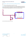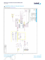
1
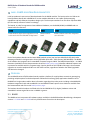
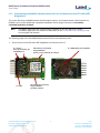
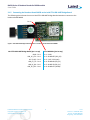
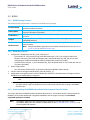
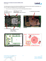
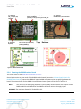
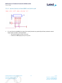
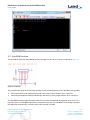
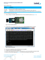
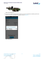
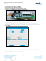
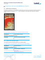
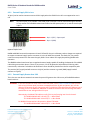
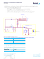
User Guide Bx600 Breakout Board Series For BL600 Modules – Bluetooth Low Energy Single Mode Version 1.3 Version 1.0 of BA600-0x, BC600-0x, BB600-0x Bx600 Series of Breakout Boards for BL600 module User Guide REVISION HISTORY Version 1.0 1.1 1.2 1.3 Date 09 Sept 2015 28 Sept 2015 21 Oct 2015 24 Nov 2015 Notes Initial Release Fixed JTAG Schematic Glitch Changed J2 errors – changed to J3 (pin3) Restructured. Updates to key features of each variant. Reorganized to create sections on Use and Testing and Power Supply Options for BL600 Breakout Boards. Added Bx600 Series Breakout Board Schematic. Removed section on JTAG. Embedded Wireless Solutions Support Center: http://ews-support.lairdtech.com www.lairdtech.com/bluetooth 2 Approver Raj Khatri Jonathan Kaye Raj Khatri Jonathan Kaye Laird Americas: +1-800-492-2320 Europe: +44-1628-858-940 Hong Kong: +852 2923 0610 Bx600 Series of Breakout Boards for BL600 module User Guide CONTENTS Laird - BL600 series Mini Development Kits .......................................................................................................4 Overview.............................................................................................................................................................4 2.1 BA600 .........................................................................................................................................................4 2.1.1 BA600 Package Contents ....................................................................................................................5 2.1.2 BA600 Key Features ............................................................................................................................5 2.1.3 Understanding the BA600-0x Breakout Board with Coin Cell Holder and Laird FTDI USB-UART Bridge Board .......................................................................................................................................................6 2.1.4 Understanding the Laird FTDI USB-UART Bridge Board .....................................................................7 2.1.5 Connecting the Breakout Board BA600 to the Laird FTDI USB-UART Bridge Board...........................8 2.2 BC600..........................................................................................................................................................9 2.2.1 BC600 Package Contents ....................................................................................................................9 2.2.2 BC600 Key Features ............................................................................................................................9 2.2.3 Understanding the BC600 Breakout Board with Integrated Coin Cell Holder ...................................9 2.3 BB600....................................................................................................................................................... 11 2.3.1 BB600 Package Contents ................................................................................................................. 11 2.3.2 BB600 Key Features ......................................................................................................................... 11 2.3.3 Understanding the BB600 Breakout Board ..................................................................................... 11 2.3.4 Powering the BB600 Breakout Board .............................................................................................. 12 Use and Testing ............................................................................................................................................... 14 3.1 Breakout Board PTH vias, J3 and J5 Signal Mapping to Bx600-07 Module ............................................. 14 3.2 UART smartBASIC Firmware Upgrade through Laird FTDI USB-UART Bridge Board............................... 15 3.3 AutoRUN Function ................................................................................................................................... 17 3.4 VSP Command Mode ............................................................................................................................... 20 Power Supply Options for BL600 Breakout Boards ......................................................................................... 23 4.1 CR1632 Coin Cell Battery ......................................................................................................................... 23 4.1.1 CR1632 Coin Cell Battery Holder ..................................................................................................... 23 4.1.2 Inserting CR1632 Coin Cell Battery into Holder............................................................................... 24 4.2 External System VCC via J4 or U3 ............................................................................................................ 24 4.2.1 External Supply 3.6V or Less ............................................................................................................ 25 4.2.2 External Supply Greater than 3.6V .................................................................................................. 25 Appendix I – Non-populated Circuitry on Breakout Boards ............................................................................ 27 5.1 ADC Input Voltage Scaling through R4, R5, and C5 ................................................................................. 27 5.2 SPI EEPROM U2........................................................................................................................................ 28 Bx600 Series Breakout Board Schematic ......................................................................................................... 29 Ordering Information ...................................................................................................................................... 30 Additional Documentation .............................................................................................................................. 30 Embedded Wireless Solutions Support Center: http://ews-support.lairdtech.com www.lairdtech.com/bluetooth 3 Laird Americas: +1-800-492-2320 Europe: +44-1628-858-940 Hong Kong: +852 2923 0610 Bx600 Series of Breakout Boards for BL600 module User Guide LAIRD - BL600 SERIES MINI DEVELOPMENT KITS Laird has produced a new series of breakout boards for the BL600 modules. The basic product is a PCB carrier board (breakout board) with a BL600-SA-07 version module soldered on it to enable rapid prototyping capabilities and help advance the product design cycle. The three part numbers from this series represent BOM (bill of material) variants of a basic core design. The boards, in order from greatest to least additional hardware, are the BA600, BC600, and BB600 and are shown below for reference: BA600 BB600 BC600 BL600 breakout board with integrated coin cell holder and Laird FTDI USB-UART bridge board BL600 breakout board BL600 breakout board with integrated coin cell holder Each of the breakout boards uses the latest BL600 module variant (top level part # BL600-SA-07) which takes advantage of Nordic’s third generation silicon (nRF51822-QFAA-Hx0 – 256k memory/16k RAM QFN). The BL600SA-07 module also integrates Laird’s smartBASIC firmware image v1.8.88.0. The BL600 Release Notes – v1.8.88.0 document (available from the Documentation tab of the BL600 product page) identifies additional features and improvements available with this firmware image. One key benefit of the v1.8.88.0 FW image is that firmware upgrades can now be completed 100% over the UART interface, regardless of whether the underlying Nordic soft device has changed. OVERVIEW The Laird Bx600 series of BLE breakout boards provides a platform for rapid wireless connectivity prototyping, providing multiple options for the development of Bluetooth Low Energy (BLE) applications based on Laird’s BL600 BTv4.0 single mode modules. More information regarding this product series including a detailed BL600 Hardware Integration Guide and smartBASIC Core and BL600 firmware-specific User Guides are available from the Documentation tab of the Laird BL600 product pages. The breakout board kit hardware is offered with the Laird BL600-SA-07 (or higher) hardware variant and smartBASIC runtime engine FW version v1.8.88.0 or greater. 2.1 BA600 The BA600 variant incorporates all hardware options available in the BL600 Breakout Board design, subsequent sections 2.2. BC600 and 2.3. BB600 will only list differences from this main description: Embedded Wireless Solutions Support Center: http://ews-support.lairdtech.com www.lairdtech.com/bluetooth 4 Laird Americas: +1-800-492-2320 Europe: +44-1628-858-940 Hong Kong: +852 2923 0610 Bx600 Series of Breakout Boards for BL600 module User Guide 2.1.1 BA600 Package Contents The followings table outlines what is included in the BA600 product package: The breakout board has the BL600-SA-07 module soldered on and exposes all available hardware interfaces. Laird FTDI USBLaird FTDI USB to 3.3VTTL-UART Bridge Board. This miniature PCB connects to the UART Bridge Board breakout board to provide serial communications between a PC and the BL600 module. USB from a PC through the Laird FTDI USB-UART Bridge Board, VCC = 3.3V Battery option via integrated Coin-cell holder (CR1632)* Power Options 1.8V to 3.6V range through J4 (plated through hole) *No coin cell battery is provided. J5 (1x6) 6-pin, 2.0 mm pitch header that allows configuration of vSP and nAUtoRUN functions. Pin Header x 2 J3 (1x6) 6-pin, 2.54 mm pitch, right-angle header that allows connection from the Laird FTDI USB-UART Bridge Board, included. 2 x jumpers for use with J5 (2.0 mm pitch) pin header to set configuration for vSP and Jumpers nAutoRUN functions. USB Cable USB A to Micro USB B Cable – black, 1.2m Provides links to Support, Documentation, Utilities, sample applications, videos and firmware. Web link card Note: Sample smartBASIC applications are available to download from the Laird BL600 product pages or via BL600 GitHub page.. Breakout Board 2.1.2 BA600 Key Features UART access (via J3) and Laird USB to UART FTDI bridge board. – 6-pin right-angle header (J3, with 2.54mm pitch) brings out BL600 module VCC, GND, and UART pins (TX, RX, CTS, RTS). – The Laird FTDI board is USB (PC) to UART bridge that allows the BL600-07 module UART to interface with a PC USB. Power supply options (no added components needed): – Regulated 3.3V into J3 (pin3) – generated by Laird FTDI board from USB (PC) – Coin-cell battery holder (fits CR1632), J2 (fitted on underside of BA600 breakout board) – 1.8V to 3.6V range through J4 (plated through hole) Jumpers (used to configure nAutoRUN [SIO_28] and vSP [SIO_7]). Analog input sensing with optional resistive divider (R4 and R5) to scale down external voltages to below BL600-07 series module ADC pin maximum. Note: You must fit R5 and modify R4 value to scale. See Appendix 5.1. for more information on ADC. smartBASIC FW upgrade capability: – Via UART (using the Laird FTDI USB-UART bridge board) smartBASIC application loading capability: – Via UART (using the Laird FTDI USB-UART bridge board) – Via Laird’s vSP OTA app from Android or iOS or Laird Central role BLE radio running a smartBASIC vSP OTA script Embedded Wireless Solutions Support Center: http://ews-support.lairdtech.com www.lairdtech.com/bluetooth 5 Laird Americas: +1-800-492-2320 Europe: +44-1628-858-940 Hong Kong: +852 2923 0610 Bx600 Series of Breakout Boards for BL600 module User Guide 2.1.3 Understanding the BA600-0x Breakout Board with Coin Cell Holder and Laird FTDI USB-UART Bridge Board This section describes the BA600 breakout board hardware options. This breakout board is delivered with the BL600-07 series module loaded with integrated smartBASIC runtime engine firmware; but no onboard smartBASIC application is loaded. Note: smartBASIC applications are simple and easy to develop for any BLE application. Sample smartBASIC applications are available to download from the Laird BL600 product webpage or via the Laird global FAE network. The following images show the BA600 breakout board from the top and bottom sides. Shown with the Laird FTDI USB-UART Bridge Board unconnected from J3. J5 – Access to SIO_7 (pin 5) and (SIO_28) nAutoRUN (pin 2) PTH via holes (1.27 mm pitch) bring out BL600-07 pins SIO_1 to SIO_8 and SIO_25 to SIO_30 J2 – CR1632 Battery Coin-cell Holder J3 pin1 Bottom Top J3 – UART PTH via holes (1.27 mm pitch) bring out BL600-07 pins SIO_8 to SIO_20. Embedded Wireless Solutions Support Center: http://ews-support.lairdtech.com www.lairdtech.com/bluetooth 6 Laird Americas: +1-800-492-2320 Europe: +44-1628-858-940 Hong Kong: +852 2923 0610 Bx600 Series of Breakout Boards for BL600 module User Guide Figure 1: BA600 breakout board 2.1.4 Understanding the Laird FTDI USB-UART Bridge Board The following is a picture of the Laird FTDI USB-UART bridge board supplied with the BA600. Top GND – pin 1 Micro-USB Type-B B_PC_CTS – Pin 2 CC (3.3V) – Pin 3 USB_PC_TX – Pin 4 USB_PC_RX – Pin 5 USB_PC_RTS – Pin 6 Bottom Micro-USB Type-B Figure 2: FTDI USB-UART bridge board supplied with the BA600 breakout board with integrated coin cell holder. The BA600 is the only breakout board package that is supplied with the Laird FTDI USB-UART bridge board which allows the BL600 series module to physically connect to a PC for ease of development. The Laird FTDI USB-UART bridge board provides USB-to-Virtual COM port conversion through a FTDI chip (part number FT232R). Any Windows PC (XP or later) should auto-install the necessary drivers; if your PC cannot locate the drivers, you can download them from http://www.ftdichip.com/Drivers/VCP.htm Embedded Wireless Solutions Support Center: http://ews-support.lairdtech.com www.lairdtech.com/bluetooth 7 Laird Americas: +1-800-492-2320 Europe: +44-1628-858-940 Hong Kong: +852 2923 0610 Bx600 Series of Breakout Boards for BL600 module User Guide 2.1.5 Connecting the Breakout Board BA600 to the Laird FTDI USB-UART Bridge Board The following picture shows the correct Laird FTDI USB-UART bridge board orientation to connect to the breakout board BA600. Pin 1 Figure 3: FTDI USB-UART bridge board orientation to connect to the breakout board BA600 Laird FTDI USB-UART Bridge Board (pin 1 at top) GND – Pin 1 USB_PC_CTS – Pin 2 VCC (3.3V) – Pin 3 USB_PC_TX – Pin 4 USB_PC_RX – Pin 5 USB_PC_RTS – Pin 6 Embedded Wireless Solutions Support Center: http://ews-support.lairdtech.com www.lairdtech.com/bluetooth J3 on BA600-0x (pin1 at top) Pin 1 – GND Pin 2 – BL600 RTS (SIO_23) Pin 3 – (VCC 3.3V input) Pin 4 – BL600 RX (SIO_22) Pin 5 – BL600 TX (SIO_21) Pin 6 – BL600 CTS (SIO24) 8 Laird Americas: +1-800-492-2320 Europe: +44-1628-858-940 Hong Kong: +852 2923 0610 Bx600 Series of Breakout Boards for BL600 module User Guide 2.2 BC600 2.2.1 BC600 Package Contents The followings table outlines what is included in the BC600 product package: Breakout Board Power Option Pin Header x 1 Jumpers Web Link Card The breakout board has the required BL600-07 module soldered on and it exposes all available hardware interfaces. Battery option via integrated coin-cell holder (CR1632*), 1.8V to 3.6V range. *No coin cell battery is provided. J5 (1x6) 6-pin, 2.0 mm pitch header that allows configuration of vSP and nAUtoRUN functions. 2 x jumpers for use with J5 (2.0 mm pitch) pin header to set configuration for vSP and nAutoRUN functions. Provides links to Support, Documentation, Utilities, sample applications, videos and latest firmware. Note: Sample smartBASIC applications are available to download from the Laird BL600 product pages or via BL600 GitHub page. 2.2.2 BC600 Key Features Configurable nAutoRUN pin and SIO_7 (vSP, OTA) with J5. – 6-pin header (J5, 2.0 mm pitch) brings out BL600 module pin 9, SIO_7 (to configure module vSP between Command, OTA, mode and Bridge mode), and nAutoRUN pin 40, [SIO_28] (for use with configuring the module into AutoRUN mode or development [interactive] mode). – J5 header allows vSP [SIO _7] and nAutoRUN [SIO_28] to be pulled either to VCC or GND with the aid of jumpers (included). Power supply option: – Coin-cell battery CR1632 holder, J2 (fitted on underside of BC600 breakout board) Jumpers (used to configure nAutoRUN [SIO_28] and vSP [SIO_7]). Analog input sensing with optional resistive divider (R4 and R5) to scale down external voltages to below BL600-07 series module ADC pin maximum. Note: You must fit R5 and modify R4 value to scale. See Appendix section 5.1. for more information on ADC. smartBASIC application loading capability - Via Laird’s vSP OTA app from Android or iOS or Laird Central role BLE radio running a smartBASIC vSP OTA script 2.2.3 Understanding the BC600 Breakout Board with Integrated Coin Cell Holder This section describes the BC600 breakout board hardware options. This breakout board is delivered with the BL600-07 series module loaded with integrated smartBASIC runtime engine firmware; but no onboard smartBASIC application is loaded. Note: smartBASIC applications are simple and easy to develop for any BLE application. Sample smartBASIC applications are available to download from the Laird BL600 product webpage or via the Laird global FAE network. Embedded Wireless Solutions Support Center: http://ews-support.lairdtech.com www.lairdtech.com/bluetooth 9 Laird Americas: +1-800-492-2320 Europe: +44-1628-858-940 Hong Kong: +852 2923 0610 Bx600 Series of Breakout Boards for BL600 module User Guide The following picture shows the breakout board BC600-0x’s top and bottom side. Breakout board BC600 is the same as breakout board BA600 but with the following changes: J3 (connector for connecting to Laird FTDI USB-UART Bridge Board) removed. J5 – Access to SIO_7 (pin 5) and (SIO_28) nAutoRUN (pin 2) PTH via holes (1.27 mm pitch) bring out BL600-07 pins SIO_1 to SIO_8 and SIO_25 to SIO_30 J2 – CR1632 Battery Coin-cell Holder Bottom Top J3 – Removed J3 (UART) PTH via holes (1.27 mm pitch) bring out BL600-07 pins SIO_8 to SIO_20. Figure 4: BC600 breakout board Embedded Wireless Solutions Support Center: http://ews-support.lairdtech.com www.lairdtech.com/bluetooth 10 Laird Americas: +1-800-492-2320 Europe: +44-1628-858-940 Hong Kong: +852 2923 0610 Bx600 Series of Breakout Boards for BL600 module User Guide 2.3 BB600 2.3.1 BB600 Package Contents The followings table outlines what is included in the BB600 product package. Breakout Board Web Link Card The breakout board has the required BL600-07 module soldered on and it exposes all available hardware interfaces. Provides links to Support, Documentation, Utilities, sample applications, videos, and latest firmware. Note: Sample smartBASIC applications are available to download from the Laird BL600 product pages or via BL600 GitHub page. 2.3.2 BB600 Key Features The BB600 variant is the core platform for the whole Bx600 breakout board series. It has the following key features: Dimensions of breakout board PCB: 33 mm x 22 mm x 0.8 mm (±0.1 mm). BL600-07 series module soldered on-board. 28 PTH via holes (pitch 1.27 mm) bringing out BL600-07 module SIO pins. Analog input sensing with optional resistive divider (R4 and R5) to scale down external voltages to below BL600-07 series module ADC pin maximum. Note: You must fit R5 and modify R4 value to scale. See Appendix section 5.1. for more information on ADC. smartBASIC application loading capability - Via Laird’s vSP OTA app from Android or iOS or Laird Central role BLE radio running a smartBASIC vSP OTA script. Note: Some modification will be required to connect signal at J5, see section 3.4. VSP Command Mode. 2.3.3 Understanding the BB600 Breakout Board This section describes the BB600 breakout board hardware options. This breakout board is delivered with the BL600-07 series module loaded with integrated smartBASIC runtime engine firmware; but no onboard smartBASIC application is loaded. Note: smartBASIC applications are simple and easy to develop for any BLE application. Sample smartBASIC applications are available to download from the Laird BL600 product webpage or via the Laird global FAE network. The following picture is Breakout board BB600’s top and bottom side. Breakout board BB600 is same as Breakout board BA600 but with the following differences: J3 (connector for connecting to Laird FTDI Board) is removed. R2(0R), disconnects J3 Pin 3 (VCC input from Laird FTDI board on BA600), and C2(0.1uF), decoupling capacitor at VCC input to BL600 pin 10, both not fitted J5 (6-pin header connector used to configure nAutoRUN, SIO_28, and vSP, SIO_7, signals) not fitted. J2 (CR1632 Coin-cell battery holder), D1 and C3 (47uF) not fitted. Embedded Wireless Solutions Support Center: http://ews-support.lairdtech.com www.lairdtech.com/bluetooth 11 Laird Americas: +1-800-492-2320 Europe: +44-1628-858-940 Hong Kong: +852 2923 0610 Bx600 Series of Breakout Boards for BL600 module User Guide PTH via holes (1.27 mm pitch) bring out BL600-07 pins SIO_1 to SIO_8 and SIO_25 to SIO_30 J5 – Removed SIO_7 and (SIO_28) nAutoRUN J3 – Removed J3 (UART) PTH via holes (1.27 mm pitch) bring out BL600-07 pins SIO_8 to SIO_20. Top J2 – Removed CR1632 Battery Coin-cell Holder Bottom Figure 5: BB600 breakout board 2.3.4 Powering the BB600 Breakout Board This section refers to the Bx600 Breakout Board schematic. Several options exist to power each of the BL600 breakout boards (see section 4. Power Supply Options for BL600 Breakout Boards) however the BB600 will require added components prior to supplying power to the board. The easiest solution for the BB600 is listed below and more options can be found in section 4. Note: At a minimum, the decoupling capacitor, C2 (0.1uF,0402), located near the VCC input pin of the BL600 module should be fitted on the BB600 to eliminate noise at the supply input. WARNING: The maximum allowed VCC for BL600 is 3.6V. Embedded Wireless Solutions Support Center: http://ews-support.lairdtech.com www.lairdtech.com/bluetooth 12 Laird Americas: +1-800-492-2320 Europe: +44-1628-858-940 Hong Kong: +852 2923 0610 Bx600 Series of Breakout Boards for BL600 module User Guide 2.3.4.1 Quickest Solution to Power BB600: Use J5pin3 or pin6 J5 is not fitted on the BB600, this 6-pin (2mm pitch) header may optionally be fitted, otherwise attach supply leads as noted in next two bullets: – VCC positive supply at J5 pin 3 or pin 6 – Common or GND supply at J5 pin 1 or pin 4 Embedded Wireless Solutions Support Center: http://ews-support.lairdtech.com www.lairdtech.com/bluetooth 13 Laird Americas: +1-800-492-2320 Europe: +44-1628-858-940 Hong Kong: +852 2923 0610 Bx600 Series of Breakout Boards for BL600 module User Guide USE AND TESTING This section describes usage and test setup for the BL600 breakout boards. Examples and pictures reference the BA600 with setup and configuration differences for the BC600 and BB600 noted as required. Customers may have other use cases. For more application notes related to the BL600, refer to the Documentation tab from Laird’s BL600 product page. 3.1 Breakout Board PTH vias, J3 and J5 Signal Mapping to Bx600-07 Module The following images shows mapping of BL600 signals brought out to the Breakout Board PTH vias and header connectors J5 and J3. BL600 signal PTH via GND 29 SIO_25 36 SIO_26 38 SIO_27 39 SIO_29 41 SIO_30 42 SIO_1/AIN 2 SIO_2/AIN 4 SIO_3/AIN 5 SIO_4/AIN 6 (R4=0R) SIO_5/AIN 7 SIO_6/AIN 8 BL600 signal J5 GND nAutoRUN (SIO_28) VCC (3.3V) Pin 3 GND SIO_7 VCC (3.3V) Pin 6 PTH via BL600 signal 28 GND 27 SIO_20 26 SIO_19 25 SIO_18 24 SIO_17 22 nRESET 21 SIO_16 20 SIO_15 19 SIO_14 18 SIO_13 16 SIO_12 /SPI_CLK 15 SIO_11/SPI_MISO 14 SIO_10/SPI_MOSI 13 SIO_9/I2C_SCL 12 SIO_8/I2C_SDA 11 GND Pin 1 Pin 2 Pin 4 cut Pin 5 J3 on BA600-0x (pin 1 on the left) Pin 1 GND Pin 2 BL600 RTS (SIO_23) Pin 3 (VCC 3.3V input) Pin 4 BL600 RX (SIO_22) Pin 5 BL600 TX (SIO_21) Pin 6 BL600 CTS (SIO24) Figure 6: BL600-07 signals Note: The above shows the BA600 Breakout Board. Below are differences for BC600 and BB600: BC600 breakout boards has only J3 removed. BB600 removes J3, J5, and J2 (coin cell holder), as well as components R2, C2, D1, and C3. Embedded Wireless Solutions Support Center: http://ews-support.lairdtech.com www.lairdtech.com/bluetooth 14 Laird Americas: +1-800-492-2320 Europe: +44-1628-858-940 Hong Kong: +852 2923 0610 Bx600 Series of Breakout Boards for BL600 module User Guide 3.2 UART smartBASIC Firmware Upgrade through Laird FTDI USB-UART Bridge Board BL600-07 modules with smartBASIC runtime engine firmware version FWv1.8.88.0 or above is required that allows UART to be used to load and upgrade smartBASIC firmware, as well as the underlying Nordic softdevice – no JTAG interface is required. Figure 7: UART smartBASIC FW upgrade If newer than v1.8.88.0 BL600 smartBASIC firmware is available from the Software Downloads section of the Laird BL600 Series webpage; you can then upgrade the firmware through the Laird FTDI USB-UART bridge board by completing the following steps: 1. Check the BL600-07 modules with smartBASIC runtime engine FW version by typing at i 3. Figure 8: Type at i 3. 2. Close UwTerminal, but do not disconnect the BA600-0x. 3. With BA600-0x still connected to a PC through the Laird FTDI USB-UART Bridge Board interface, double click on to Laird utility BL6xxUartFwUpgrade.exe 4. Select the COM port, confirm the firmware version to be uploaded and click OK. Embedded Wireless Solutions Support Center: http://ews-support.lairdtech.com www.lairdtech.com/bluetooth 15 Laird Americas: +1-800-492-2320 Europe: +44-1628-858-940 Hong Kong: +852 2923 0610 Bx600 Series of Breakout Boards for BL600 module User Guide Figure 9: Device firmware configuration options Once the firmware upgrade is completed successfully, the Upgrade Success message displays. 5. Click Quit to close. Figure 10: Successful firmware upgrade 6. Verify the new FW has been loaded to the BL600 module by entering the command at i 3. If the upgrade is successful, the terminal echoes the new version number. Embedded Wireless Solutions Support Center: http://ews-support.lairdtech.com www.lairdtech.com/bluetooth 16 Laird Americas: +1-800-492-2320 Europe: +44-1628-858-940 Hong Kong: +852 2923 0610 Bx600 Series of Breakout Boards for BL600 module User Guide Figure 11: Verify loaded firmware 3.3 AutoRUN Function The nAUTORUN signal (SIO_28 of BL600; pin 40) is brought out onto J5 pin 2. See the schematic in Figure 12. Figure 12: J5 schematic The nAutoRUN pin needs to be externally held high or low to select between the two BL600 operating modes: Self-contained Run mode (nAutoRUN pin held at 0V). Insert jumper between J5 Pin 2 and Pin 1. Interactive/Development mode (nAutoRUN pin held at VCC). Insert jumper between J5 Pin 2 and Pin 3. The smartBASIC runtime engine firmware checks for the status of nAutoRUN during power-up or reset. If it is low and if there is a smartBASIC application named $autorun$, then the smartBASIC runtime engine executes the application automatically; hence the name self-contained run mode. Embedded Wireless Solutions Support Center: http://ews-support.lairdtech.com www.lairdtech.com/bluetooth 17 Laird Americas: +1-800-492-2320 Europe: +44-1628-858-940 Hong Kong: +852 2923 0610 Bx600 Series of Breakout Boards for BL600 module User Guide Table 1: nAutoRun settings J5 pin2 Comments nAutoRUN Input with active low logic (SIO_28) Operating mode selected by nAutoRUN pin status: Pin 40 of If LOW (0V), runs $autorun$ if it exist. (Insert jumper between J5 Pin 2 and Pin 1) BL600 If HIGH (VCC), runs at+run and file name application (Insert jumper between J5 Pin 2 and Pin 3) To initiate autoRUN, follow these steps: 1. Start by loading a smartBASIC application that can run from autoRUN at power up (Figure 13). Figure 13: Load smartBASIC application 7. In UwTerminal, do a compile and download and select $autorun$.iBeacon.sb (for example). Figure 14: Compile and download 8. 9. 10. 11. Verify that the application exists as $autorun$ by issuing at+dir. Unplug the Laird FTDI USB-UART bridge board. Install a jumper between pins 1 and 2 of J5 (nAutoRUN set to Low to put module into autorun mode). Install a coin cell battery (CR1632)(Figure 15) in the slot on the bottom of the module. Embedded Wireless Solutions Support Center: http://ews-support.lairdtech.com www.lairdtech.com/bluetooth 18 Laird Americas: +1-800-492-2320 Europe: +44-1628-858-940 Hong Kong: +852 2923 0610 Bx600 Series of Breakout Boards for BL600 module User Guide Figure 15: Coin cell battery slot 12. Using the Laird ToolKit Proximity app (for example, just to pick up the advert) on Android, search for the beacon. If successful, the BL600 beacon displays as shown in Figure 16. Figure 16: BL600 beacon Embedded Wireless Solutions Support Center: http://ews-support.lairdtech.com www.lairdtech.com/bluetooth 19 Laird Americas: +1-800-492-2320 Europe: +44-1628-858-940 Hong Kong: +852 2923 0610 Bx600 Series of Breakout Boards for BL600 module User Guide 3.4 VSP Command Mode This section discusses VSP Command mode through pulling SIO_7 high and nAutoRUN low. Read this section in conjunction with the VSP Configuration chapter of the following guide: User Guide - smartBASIC BL600 Extensions Release 1.5.70.0.pdf Figure 17 shows the difference between VSP Bridge to UART mode and VSP OTA mode and how SIO_7 and nAutoRUN need to be configured to select between these two modes. VSP Bridge to UART mode takes data sent from phone or tablet (over BLE) and sends to BL600 to be sent out of the BL600 UART (therefore data not stored on BL600). VSP Command mode takes data sent from phone of tablet and sends to BL600 and stores that data in the BL600. The OTA Android or iOS application can be used to download any smartBASIC application script over the air to the BL600. Figure 17: Difference between VSP bridge to UART mode and VSP OTA mode Table 2: vSP Modes Mode VSP Bridge to UART Mode VSP Command Mode SIO_7 and Jumper Position on J5 High Insert jumper between J5 pin5 and 6. nAutoRUN and Jumper Position on J5 High Insert jumper between J5 pin2 and 3. High Insert jumper between J5 pin5 and 6. Low Insert jumper between J5 pin2 and 1. SIO_7 High (externally) selects the VSP service and together when nAutoRUN is Low (externally), selects VSP Command mode whilst nAutoRUN High (externally) selects VSP Bridge to UART mode. When SIO_7 on module is set HIGH (externally), VSP is enabled and auto-bridged to UART when connected. However, for VSP Command mode, auto-bridge to UART is not required. With SIO_7 set to High and nAutoRUN set to Low, VSP Command mode is entered and you can then download the smartBASIC application onto the module over the air from the phone (or tablet). SIO_7 V (BL600 pin9) is brought out onto J5 pin 5. See the following schematic (Figure 18). Embedded Wireless Solutions Support Center: http://ews-support.lairdtech.com www.lairdtech.com/bluetooth 20 Laird Americas: +1-800-492-2320 Europe: +44-1628-858-940 Hong Kong: +852 2923 0610 Bx600 Series of Breakout Boards for BL600 module User Guide Figure 18: SIO_7 is brought out onto J5 pin 5 To initiate Command mode, follow these steps: 1. Switch the BL600 out of autoRUN mode by doing the following: a. Remove the CR1632 coin cell battery. b. Move the nAutoRUN jumper between pins 2 and 3 of J5 to pull it high. c. Connect the BA600-0x to the Laird FTDI USB-UART bridge board (Figure 19). Figure 19: BA600-0x connected to the USB-UART bridge board In UwTerminal, you will notice that the BA600-0x is in Develop/Interactive mode rather than AutoRUN mode (Figure 20). Figure 20: Develop/Interactive mode Embedded Wireless Solutions Support Center: http://ews-support.lairdtech.com www.lairdtech.com/bluetooth 21 Laird Americas: +1-800-492-2320 Europe: +44-1628-858-940 Hong Kong: +852 2923 0610 Bx600 Series of Breakout Boards for BL600 module User Guide 13. 14. 15. 16. Erase the previously loaded file using AF&F*. Unplug the Laird FTDI USB-UART bridge board. Install jumper between pins 5 and 6 of J5 to pull SIO_7 high. Install jumper between pins 1 and 2 of J5 to pull nAutoRUN low. The module should now be in VSP OTA mode. 17. 18. 19. 20. Install the CR1632 coin cell battery. The BA600-0x wakes up in VSP OTA mode. Using the Laird OTA application on your mobile phone, discover and connect to the module. Browse and select your pre compiled (in this example $autorun$.iBeacon.uwc) smartBASIC application. Click Upload. Figure 21: OTA application 21. Once the download is complete, remove the jumper from SIO_7 and move the nAutoRUN jumper to position 1 and 2. 22. Reset the module. Your application is now ready to run. Embedded Wireless Solutions Support Center: http://ews-support.lairdtech.com www.lairdtech.com/bluetooth 22 Laird Americas: +1-800-492-2320 Europe: +44-1628-858-940 Hong Kong: +852 2923 0610 Bx600 Series of Breakout Boards for BL600 module User Guide POWER SUPPLY OPTIONS FOR BL600 BREAKOUT BOARDS 4.1 CR1632 Coin Cell Battery A CR1632 coin cell battery is not supplied with the breakout board. We have tested the breakout board with an Energizer CR1632 coin cell battery (Figure 22) but any CR1632 coin cell battery that meets your needs will suffice. Figure 22: CR1632 coin cell battery sample http://www.digikey.com/product-detail/en/CR1632VP/N036-ND/704854 Manufacturer Energizer Battery Company Manufacturer Part Number CR1632VP Description BATTERY LITHIUM 3V COIN 16MM Datasheets CR1632 4.1.1 CR1632 Coin Cell Battery Holder The breakout board uses following CR1632 coin cell battery holder. http://www.digikey.com/product-detail/en/3012TR/36-3012TR-ND/1978698 Manufacturer Keystone Electronics Manufacturer Part Number 3012TR Description RETAINER COMPACT 16MM SMD Datasheets 3012TR Drawing 3012 Drawing THM, SMT Coin Cell Retainers Embedded Wireless Solutions Support Center: http://ews-support.lairdtech.com www.lairdtech.com/bluetooth 23 Laird Americas: +1-800-492-2320 Europe: +44-1628-858-940 Hong Kong: +852 2923 0610 Bx600 Series of Breakout Boards for BL600 module User Guide 4.1.2 Inserting CR1632 Coin Cell Battery into Holder Figure 23 shows the CR1632 coin cell orientation for inserting into the holder. Figure 23: Inserting the coin cell battery Figure 24 shows the CR1632 coin cell inserted. Figure 24: Coin cell battery inserted into holder 4.2 External System VCC via J4 or U3 The schematic shows the BA600-0x, BC600-0x and BB600-0x Breakout Board power supply section circuitry only. WARNING: Maximum allowed VCC for BL600 is 3.6V. If an external supply voltage greater than 3.6V is used the directions in section 4.3.2. (below) should be followed to add the linear regulator, U3, and the external components needed for proper operation and connection with the VCC supply net on the BL600 breakout board. Note: The decoupling capacitor, C2 (0.1uF, 0402), should be fitted on the BB600 when connecting any VCC source. Embedded Wireless Solutions Support Center: http://ews-support.lairdtech.com www.lairdtech.com/bluetooth 24 Laird Americas: +1-800-492-2320 Europe: +44-1628-858-940 Hong Kong: +852 2923 0610 Bx600 Series of Breakout Boards for BL600 module User Guide 4.2.1 External Supply 3.6V or Less J4 (pin1) can be used to connect an external 3.6V supply when the CR1632 coin cell is not supported or not in use. Note: J4 (2.0 mm pitch, 2-pin) header is not fitted (J4 pin 1 and pin 2 can be accessed through PTH holes) on any version of the BL600 breakout board. Note that the square pad is pin 1, and the circular pad is pin 2. J4 pin 1 (VCC) – Square pad J4 pin 2 (GND) Figure 25: J4 pins 1 and 2 BA600 and BC600 come with components D1 and C3 fitted for the coin cell battery and no changes are required to support an external supply input at connector J4, coin cell MUST be removed. The diode, D1, can provide reverse current protection for the external supply while C3 can reduce VCC supply drops during BL600 radio operation. The BB600 breakout board must have a regulated external supply capable of handling the demands of the BL600 radio during transmission bursts. If there is any concern, C3 can be placed to help stabilize VCC during radio transmissions, otherwise C3 should not be fitted and a short should be placed across the D1 component pads. The positive (VCC) supply lead will connect to J4 (pin1) and the common or ground (GND) supply lead will connect to J4 (pin2). 4.2.2 External Supply Greater than 3.6V This is the use case where customer has external system VCC greater than 3.6V on any of the BL600 breakout board revisions: WARNING: If customer decides to use an off the shelf FTDI cable, such as FTDI TTL-232R-3V3 which comes with a 6-pin (2.54mm pitch) connector compatible with the J3 pitch and pinout, pin 3 of this cable has 5V present on pin3. Connecting the TTL-232R-3V3 FTDI cable from the USB port into J3 including pin 3 on the BA600-0x, BB600-0x or BC600-0x breakout board will damage the BL600 module due to over-voltage at the VCC input. Alternatively, the below FTDI cables are safe (3.3V on pin3) to plug into J3 on the board: TTL-232RG-VSW3V3-WE: 3.3V VCC/TTL --> Wire Ended TTL-232RG-VREG3V3-WE: 3.3V VCC/TTL --> Wire Ended For BL600 VCC operated at 1.8V operation, below FTDI cable: TTL-232RG-VREG1V8-WE: 1.8V VCC/TTL --> Wire Ended Embedded Wireless Solutions Support Center: http://ews-support.lairdtech.com www.lairdtech.com/bluetooth 25 Laird Americas: +1-800-492-2320 Europe: +44-1628-858-940 Hong Kong: +852 2923 0610 Bx600 Series of Breakout Boards for BL600 module User Guide All BL600 breakout board versions will require modifications, through the use of an LDO regulator, U3, to interface to an external supply of greater than 3.6V. Remove R2(0R, 0402) and fit R3(0R, 0402) Fit LDO regulator U3 (SOT-553 package, for example Toshiba TCR2EE33) Fit regulator input capacitor C8 (2.2uF, 0603 body size) Fit regulator output capacitors C6 (15pF, 0402 body size) and C7 (2.2uF, 0603 body size) R6 should NOT be fitted (DNF) for operation of the Toshiba TCR2EE33, U3, regulator 2.5mm pitch 6-way connector GND R3 1 2 3 4 5 6 BT_RTS_S23 3.3V BT_RX_S22 BT_TX_S21 BT_CTS_S24 DNF HEADER 6 J3 R2 0R VCC U3 CONTNC GND VINVOUT 5 4 DIODE DNF GND GND 1 1 + 47uF 1 2 1 2 2 GND J4 J2 C3 NOPOP (PIN HEADER,2.0mm 1X2P,) - GND C7 DNF CR1632 Battery Holder GND C6 DNF R6 DNF C8 DNF 0.1V drop accross D1[BAT60A] D1 2 1 2 3 GND GND Figure 26: External system greater than 3.6V on J2 http://www.digikey.com/product-detail/en/TCR2EE33,LM(CT/TCR2EE33LM(CTTR-ND/4965705 Manufacturer Toshiba Semiconductor and Storage Manufacturer Part Number TCR2EE33,LM(CT Description IC REG LDO 3.3V 0.2A ESV Datasheets TCR2EF,EE Series Regulator Topology Positive Fixed Voltage - Output 3.3V Current - Output 200mA Voltage - Dropout (Typical) 0.15V @ 150mA Voltage - Input Up to 5.5V Current - Limit (Min) Operating Temperature -40°C ~ 85°C Mounting Type Surface Mount Package / Case SOT-553 Supplier Device Package ESV Embedded Wireless Solutions Support Center: http://ews-support.lairdtech.com www.lairdtech.com/bluetooth 26 Laird Americas: +1-800-492-2320 Europe: +44-1628-858-940 Hong Kong: +852 2923 0610 Bx600 Series of Breakout Boards for BL600 module User Guide APPENDIX I – NON-POPULATED CIRCUITRY ON BREAKOUT BOARDS 5.1 ADC Input Voltage Scaling through R4, R5, and C5 Figure 27 schematic shows the ADC input scaling circuit only. The BA600 and BB600 breakout boards have R4 populated as 0 ohms and must be modified when R5 is fitted to match ADC configuration. Customer injects an external analog voltage (greater than BL600 Maximum allowed ADC input voltage into BL600 of 3.6V) to sense into PTH via 6. Refer to the BL600 HIG pages for how to select value of C5 that needs to be fitted. 1 6 SIO_4 C5 SIO_0 GND SIO_30 SIO_29 SIO_28 SIO_27/NC SIO_26/NC GND SIO_25 SIO_24 SIO_23 SIO_22 SIO_21 GND RF_ANT GND GND SIO_1/AIN GND SIO_2/AIN SIO_3/AIN SIO_4/AIN SIO_5/AIN SIO_6/AIN SIO_7 VCC GND SIO_8 CON_SM_44 13 14 15 16 17 18 19 20 21 22 23 24 25 26 27 28 R5 NOPOP 1 2 3 4 5 6 7 8 9 10 11 12 SIO_9 SIO_10 SIO_11 SIO_12 GND SIO_13 SIO_14 SIO_15 SIO_16 nRESET NC SIO_17 SIO_18 SIO_19 SIO_20/NC GND U1 44 43 42 41 40 39 38 37 36 35 34 33 32 31 30 29 R4 0R NOPOP GND Figure 27: ADC input voltage scaling circuit for ADC on SIO_4 Embedded Wireless Solutions Support Center: http://ews-support.lairdtech.com www.lairdtech.com/bluetooth 27 Laird Americas: +1-800-492-2320 Europe: +44-1628-858-940 Hong Kong: +852 2923 0610 Bx600 Series of Breakout Boards for BL600 module User Guide 5.2 SPI EEPROM U2 U1 1 2 3 4 5 6 7 8 9 10 11 12 SIO_0 GND SIO_30 SIO_29 SIO_28 SIO_27/NC SIO_26/NC GND SIO_25 SIO_24 SIO_23 SIO_22 SIO_21 GND RF_ANT GND 44 43 42 41 40 39 38 37 36 35 34 33 32 31 30 29 Figure 28 schematic shows the SPI EEPROM IC (U2) circuit only. GND SIO_1/AIN GND SIO_2/AIN SIO_3/AIN SIO_4/AIN SIO_5/AIN SIO_6/AIN SIO_7 VCC GND SIO_8 13 14 15 16 17 18 19 20 21 22 23 24 25 26 27 28 SIO_9 SIO_10 SIO_11 SIO_12 GND SIO_13 SIO_14 SIO_15 SIO_16 nRESET NC SIO_17 SIO_18 SIO_19 SIO_20/NC GND CON_SM_44 14 15 16 1 1 1 18 1 BT_SMOSI_S10 BT_SMISO_S11 BT_SCLK_S12 SIO_13 Figure 28: SPI EEPROM (U2) VCC R1 DNF 1 2 3 4 SIO_13 BT_SMISO_S11 VCC U2 CS# SO/SIO1 WP# GND VCC HOLD# CLK SI/SIO0 8 7 6 5 C4 DNF VCC BT_SCLK_S12 BT_SMOSI_S10 GND DNF GND Figure 29: SPI EEPROM Customer may wish to make use of SPI EEPROM U2 in the end application, U2 MPN details is as follows. R1 is 10K(0402) and C4 0.1uF(0402).The MX25L4006E may be order from suppliers such as Digikey. Manufacturer Macronix Manufacturer Part Number MX25L4006EZUI-12G TR Description IC FLASH 4MBIT 86MHZ 8USON Datasheets MX25L4006E Memory Type FLASH - NOR Memory Size 4M (512K x 8) Speed 86MHz Interface SPI Serial Voltage - Supply 2.7 V ~ 3.6 V Embedded Wireless Solutions Support Center: http://ews-support.lairdtech.com www.lairdtech.com/bluetooth 28 Laird Americas: +1-800-492-2320 Europe: +44-1628-858-940 Hong Kong: +852 2923 0610 Bx600 Series of Breakout Boards for BL600 module User Guide BX600 SERIES BREAKOUT BOARD SCHEMATIC For full size version, download here. Embedded Wireless Solutions Support Center: http://ews-support.lairdtech.com www.lairdtech.com/bluetooth 29 Laird Americas: +1-800-492-2320 Europe: +44-1628-858-940 Hong Kong: +852 2923 0610 Bx600 Series of Breakout Boards for BL600 module User Guide ORDERING INFORMATION Part Number DESCRIPTION BB600 BC600 BA600 Breakout Board for BL600-SA Module Breakout Board for BL600-SA including Coin Cell Holder Breakout kit for BL600-SA module including USB - UART bridge board ADDITIONAL DOCUMENTATION Laird offers a variety of documentation and ancillary information to support our customers through the initial evaluation process and ultimately into mass production. Additional documentation can be accessed from the Documentation tab of the Laird BL600 Product Page or from the BL600 section of the Embedded Wireless Solutions Support Center. BL600 Hardware Integration Guide smartBASIC BL600 Extensions Release 1.5.70.0 User Guide - BL600 smartBASIC Module Release 1.5.66.0 User Guide - BL600-DVK (Board Revision 4 or Below) User Guide - smartBASIC Core Functionality User Guide - StringPlayer User Guide - BL600-DVK (Board Revision 5) Quick Start Guide - PPK-BL600 Programming jig for BL600 modules Quick Start Guide - BL600-DVK smartBASIC Proximity Profile Quick Start Guide - BL600-DVK Heart Rate Quick Start Guide – UwTerminal Application Note - BL600 Cable Replacement Mode Application Note - BL600 Recommended 128 bit Custom UUID Management Application Note - Laird BL600 Range Testing Application Note - BL600 Whisper Mode Application Note - BL600 Using Notepad++ and Color Syntax Highlighting Application Note - BL600 Using Textpad and Color Syntax Highlighting Application Note - BL600 Using UART Efficiently to Extend Battery Life Application Note - Default DVK-BL600 DIP Switch and Jumper Settings Application Note - Flash Cloning for the BL600 Application Note - Finding the BL600-Sx Revision Number Application Note - Upgrading BL600 Firmware via JTAG Application Note - Upgrading BL600 Firmware via UART Application Note - Bluetooth Latency and Data Application Note - iBeacon Sample App Application Note - Using VSP with smartBASIC Batch Application Notes for iOS Serial Application Notes for iOS Application Note - BL6x0 Over-the-Air Application Download Application Note - smartBASIC for BLE Modules OTA Application Notes for iOS Application Note - BL600 and BL620 Memory Map Overview Application Note - smartBASIC App Download Protocol over UART Application Note - BL600 BT SIG Qualification v1.0 Application Note - Using SPI Interface in smartBASIC with DotStar Release Note - BL600 Firmware v1.5.70.0 Laird Warranty Statement For any additional questions or queries, or to receive technical support for this Development Kit or for the BL600 module series, please contact the Embedded Wireless Solutions Support Center: http://ewssupport.lairdtech.com Embedded Wireless Solutions Support Center: http://ews-support.lairdtech.com www.lairdtech.com/bluetooth 30 Laird Americas: +1-800-492-2320 Europe: +44-1628-858-940 Hong Kong: +852 2923 0610