1
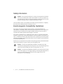
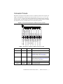
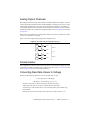
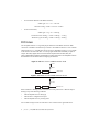
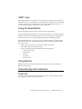
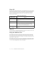
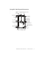
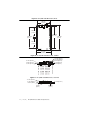
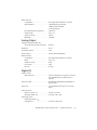
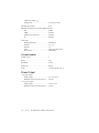
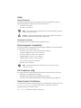
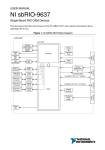
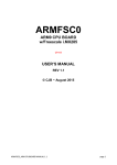
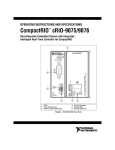
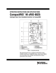
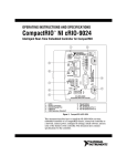
USER GUIDE AND SPECIFICATIONS NI myRIO-1950 The National Instruments myRIO-1950 is an embedded reconfigurable I/O (RIO) device that students can use to design control, robotics, and mechatronics systems. This document contains pinouts, connectivity information, dimensions, mounting instructions, and specifications for the NI myRIO-1950. Figure 1. NI myRIO-1950 1 2 3 4 45 46 11 10 7 9 8 1 2 3 4 5 6 Reset Button Power Connector Device USB Connector Host USB Connector Mounting Hole Connected to Chassis Ground (x6) LEDs 7 8 9 10 11 DDR3 Memory User Button MXP Connector B, Pin 1 Processor/FPGA MXP Connector A, Pin 1 Safety Information Do not operate the hardware in a manner not specified in this document and in the user documentation. Misuse of the hardware can result in a hazard. You can compromise the safety protection if the hardware is damaged in any way. If the hardware is damaged, return it to National Instruments for repair. Caution Clean the hardware with a soft, nonmetallic brush. Make sure that the hardware is completely dry and free from contaminants before returning it to service. Electromagnetic Compatibility Guidelines This product was tested and complies with the regulatory requirements and limits for electromagnetic compatibility (EMC) stated in the product specifications. These requirements and limits provide reasonable protection against harmful interference when the product is operated in the intended operational electromagnetic environment. This product is intended for use in commercial locations. There is no guarantee that harmful interference will not occur in a particular installation or when the product is connected to a test object. To minimize interference with radio and television reception and prevent unacceptable performance degradation, install and use this product in strict accordance with the instructions in the product documentation. Furthermore, any modifications to the product not expressly approved by National Instruments could void your authority to operate it under your local regulatory rules. To ensure the specified EMC performance, the length of any cable connected to the USB ports must be no longer than 3 m (10 ft), and the length of any cable connected to the MXP ports must be no longer than 0.3 m (1 ft). Caution To ensure the specified EMC performance, do not connect the power input to a DC mains supply or to any supply requiring a connecting cable longer than 3 m (10 ft). A DC mains supply is a local DC electricity supply network in the infrastructure of a site or building. Caution 2 | ni.com | NI myRIO-1950 User Guide and Specifications ESD Warning Although this product has been designed to be as robust as possible, ESD (electrostatic discharge) can damage or upset this product. This product must be protected at all times from ESD. Static charges may easily produce potentials of several kilovolts on the human body or equipment, which can discharge without detection. Industry-standard ESD precautions must be employed at all times. Caution The NI myRIO-1950 is designed and intended for use as a development platform for hardware or software in an educational/professional laboratory environment. To facilitate usage, the board is manufactured with its components and connecting traces openly exposed to the operator and the environment. As a result, ESD sensitive (ESDS) components on the board, such as the semiconductor integrated circuits, can be damaged when exposed to an ESD event. To indicate the ESD sensitivity of the NI myRIO-1950, it carries the symbol shown below. NI myRIO-1950 User Guide and Specifications | © National Instruments | 3 Hardware Overview The NI myRIO-1950 provides analog input (AI), analog output (AO), digital input and output (DIO), and power output in a compact embedded device. The NI myRIO-1950 connects to a host computer over USB. The following figure shows the arrangement and functions of NI myRIO-1950 components. Figure 2. NI myRIO-1950 Hardware Block Diagram Reset Button USB Device Port USB Host Port Xilinx Zynq-7010 Nonvolatile Memory Watchdog DDR3 Processor (LabVIEW RT) Status LED (x2) MXP A/B User LEDs +3.3 V UART 16 2 4 DIO 16 AO AI FPGA (LabVIEW FPGA) Accelerometer 4 | ni.com | NI myRIO-1950 User Guide and Specifications Button0 Connector Pinouts NI myRIO-1950 Expansion Port (MXP) connectors A and B carry identical sets of signals. The signals are distinguished in software by the connector name, as in ConnectorA/DIO1 and ConnectorB/DIO1. Refer to the software documentation for information about configuring and using signals. The following figure and table show the signals on MXP connectors A and B. Note that some pins carry secondary functions as well as primary functions. AI1 AI0 +5V 3 1 34 32 30 28 26 24 22 20 18 16 14 12 10 8 6 4 2 AO1 AO0 UART.RX DGND UART.TX DGND DIO11 / ENC.A DGND DIO12 / ENC.B DGND DIO13 DGND DGND DIO14 / I2C.SCL DIO15 / I2C.SDA AGND 5 AI3 7 33 31 29 27 25 23 21 19 17 15 13 11 9 DGND AI2 DIO0 DIO1 DIO2 DIO3 DIO4 DIO5 / SPI.CLK DIO6 / SPI.MISO DIO7 / SPI.MOSI DIO8 / PWM0 DIO9 / PWM1 DIO10 / PWM2 +3.3 V Figure 3. Primary/Secondary Signals on MXP Connectors A and B Table 1. Descriptions of Signals on MXP Connectors A and B Signal Name Reference Direction Description +5V DGND Output AI <0..3> AGND Input 0-5 V, referenced, single-ended analog input channels. Refer to the Analog Input Channels section for more information. AO <0..1> AGND Output 0-5 V referenced, single-ended analog output. Refer to the Analog Output Channels section for more information. AGND N/A N/A +3.3V DGND Output +5 V power output. Reference for analog input and output. +3.3 V power output. NI myRIO-1950 User Guide and Specifications | © National Instruments | 5 Table 1. Descriptions of Signals on MXP Connectors A and B (Continued) Signal Name Reference Direction Description DIO <0..15> DGND Input or Output General-purpose digital lines with 3.3 V output, 3.3 V/5 V-compatible input. Refer to the DIO Lines section for more information. UART.RX DGND Input UART.TX DGND Output DGND N/A N/A UART receive input. UART lines are electrically identical to DIO lines. UART transmit output. UART lines are electrically identical to DIO lines. Reference for digital signals, +5 V, and +3.3 V. Analog Input Channels The NI myRIO-1950 has analog input channels on myRIO Expansion Port (MXP) connectors A and B. The analog inputs are multiplexed to a single analog-to-digital converter (ADC) that samples all channels. MXP connectors A and B have four single-ended analog input channels per connector, AI0-AI3, which you can use to measure 0-5 V signals. Note For important information about improving measurement accuracy by reducing noise, go to ni.com/info and enter the Info Code analogwiring. Figure 4 shows the analog input topology of the NI myRIO-1950. Figure 4. NI myRIO-1950 Analog Input Topology AI0 MXP A AI1 AI2 AI3 MUX 0–5 V AI0 MXP B AI1 AI2 AI3 6 | ni.com | NI myRIO-1950 User Guide and Specifications ADC Analog Output Channels The NI myRIO-1950 has analog output channels on myRIO Expansion Port (MXP) connectors A and B. Each analog output channel has a dedicated digital-to-analog converter (DAC), so they can all update simultaneously. The DACs for the analog output channels are controlled by a serial communication bus from the FPGA. MXP connectors A and B share one bus Therefore, the maximum update rate is specified as an aggregate figure in the Analog Output section of the Specifications. MXP connectors A and B have two analog output channels per connector, AO0 and AO1, which you can use to generate 0-5 V signals. Figure 5 shows the analog output topology of the NI myRIO-1950. Figure 5. NI myRIO-1950 Analog Output Topology DAC AO0 DAC AO1 MXP A 0–5 V DAC AO0 DAC AO1 MXP B Accelerometer The NI myRIO-1950 contains a three-axis accelerometer. The accelerometer samples each axis continuously and updates a readable register with the result. Refer to the Accelerometer section of the Specifications for the accelerometer sample rates. Converting Raw Data Values to Voltage You can use the following equations to convert raw data values to volts: V = Raw Data Value * LSB Weight LSB Weight = Nominal Range ÷ 2ADC Resolution where Raw Data Value is the value returned by the FPGA I/O Node, LSB Weight is the value in volts of the increment between data values, Nominal Range is the absolute value in volts of the full, peak-to-peak nominal range of the channel, and ADC Resolution is the resolution of the ADC in bits. (ADC Resolution = 12.) NI myRIO-1950 User Guide and Specifications | © National Instruments | 7 • For AI and AO channels on the MXP connectors, LSB Weight = 5 V ÷ 212 = 1.221 mV Maximum reading = 4095 * 1.221 mV = 4.999 V • For the accelerometer, LSB Weight = 16 g ÷ 212 = 3.906 mg Maximum Positive Reading = +2047 * 3.906 mg = +7.996 g Maximum Negative Reading = -2048 * 3.906 mg = -8.000 g DIO Lines The NI myRIO-1950 has 3.3 V general-purpose DIO lines on the MXP connectors. MXP connectors A and B have 16 DIO lines per connector. Each DIO line from 0 to 13 has a 40 kΩ pullup resistor to 3.3 V, and DIO lines 14 and 15 have 2.1 kΩ pullup resistors to 3.3 V. DGND is the reference for all the DIO lines. You can program all the lines individually as inputs or outputs. Secondary digital functions include Serial Peripheral Interface Bus (SPI), I2C, pulse-width modulation (PWM), and quadrature encoder input. Refer to the NI myRIO software documentation for information about configuring the DIO lines. Figure 6. DIO Lines <13..0> on MXP Connector A or B +3.3 V 40 kΩ FPGA Bus Switch DIO<13..0> Figure 7. DIO Lines <15..14> on MXP Connector A or B +3.3 V 2.1 kΩ FPGA Bus Switch DIO<15..14> When a DIO line is floating, it floats in the direction of the pull resistor. A DIO line may be floating in any of the following conditions: • when the myRIO device is starting up • when the line is configured as an input • when the myRIO device is powering down You can add a stronger resistor to a DIO line to cause it to float in the opposite direction. 8 | ni.com | NI myRIO-1950 User Guide and Specifications UART Lines The NI myRIO-1950 has one UART receive input line and one UART transmit ouput line on each MXP connector. The UART lines are electrically identical to DIO lines 0 to 13 on the MXP connectors. Like those lines, UART.RX and UART.TX have 40 kΩ pullup resistors to 3.3 V. Use LabVIEW Real-Time to read and write over the UART lines. Using the Reset Button Pressing and releasing the Reset button restarts the processor and the FPGA. Pressing and holding the Reset button for 5 seconds, then releasing it, restarts the processor and the FPGA and forces the NI myRIO-1950 into safe mode. In safe mode, the NI myRIO-1950 launches only the services necessary for updating configuration and installing software. When the NI myRIO-1950 is in safe mode, you can communicate with it by using the UART lines on MXP connector A. You need the following items to communicate with the myRIO device over UART: • USB-to-TTL serial UART converter cable (for example, part number TTL-232RG-VSW3V3-WE from FTD Chip) • Serial-port terminal program configured with the following settings: • 115,200 bits per second • Eight data bits • No parity • One stop bit • No flow control Using Button0 Button0 produces a logic TRUE when depressed and a logic FALSE when not depressed. Button0 is not debounced. Understanding LED Indications Power LED The Power LED is lit while the NI myRIO-1950 is powered on. This LED indicates that the power supply connected to the device is adequate. NI myRIO-1950 User Guide and Specifications | © National Instruments | 9 Status LED The Status LED is off during normal operation. The NI myRIO-1950 runs a power-on self test (POST) when you apply power to the device. During the POST, the Power and Status LEDs turn on. When the Status LED turns off, the POST is complete. The NI myRIO-1950 indicates specific error conditions by flashing the Status LED a certain number of times every few seconds, as shown in Table 2. Table 2. Status LED Indications Number of Flashes Every Few Seconds Indication 2 The device has detected an error in its software. This usually occurs when an attempt to upgrade the software is interrupted. Reinstall software on the device. 3 The device is in safe mode. 4 The software has crashed twice without rebooting or cycling power between crashes. This usually occurs when the device runs out of memory. Review your RT VI and check the memory usage. Modify the VI as necessary to solve the memory usage issue. Continuously flashing or solid The device has detected an unrecoverable error. Contact National Instruments. LEDs 0-3 You can use LEDs 0-3 to help debug your application or easily retrieve application status. Logic TRUE turns an LED on and logic FALSE turns an LED off. Using the USB Host Port The NI myRIO-1950 USB host port supports Web cameras that conform to the USB Video Device Class (UVC) protocol as well as machine vision cameras that conform to the USB3 Vision standard and are USB 2.0 backward compatible. The NI myRIO-1950 USB host port also supports Basler ace USB3 cameras. The NI myRIO-1950 USB host port also supports USB Flash drives and USB-to-IDE adapters formatted with FAT16 and FAT32 file systems. LabVIEW usually maps USB devices to the /U, /V, /W, or /X drive, starting with the /U drive if it is available. 10 | ni.com | NI myRIO-1950 User Guide and Specifications NI myRIO-1950 Physical Dimensions Figure 8. NI myRIO-1950 Dimensions, Front 40.6 mm (1.6 in.) 2.5 mm (0.10 in.) 72.5 mm (2.86 in.) 130.7 mm (5.15 in.) 122.8 mm (4.83 in.) 118.7 mm (4.68 in.) 115.3 mm (4.54 in.) 108.4 mm (4.27 in.) 32 x 2.5 mm (0.10 in.) 91.4 mm (3.6 in.) 84.5 mm (3.33 in.) 77.7 mm (3.06 in.) 70.8 mm (2.79 in.) 69.1 mm (2.72 in.) Pin 1 73.6 mm (2.90 in.) 61.6 mm (2.43 in.) 57.9 mm (2.28 in.) Height 1.19 mm (0.047 in.) 44.0 mm (1.73 in.) 61.7 mm (2.43 in.) Height 1.60 mm (0.063 in.) Height 0.99 mm (0.039 in.) 6 x maximum fastener head or standoff Ø is 6.86 mm (0.27 in.) Pin 1 16.5 mm (0.65 in.) 12.0 mm (0.47 in.) 8.0 mm (0.31 in.) 0.0 mm (0.0 in.) 77.7 mm (3.06 in.) 82.7 mm (3.26 in.) 66.2 mm (2.61 in.) 60.4 mm (2.38 in.) 9.7 mm (0.38 in.) 2 x 7.1 mm (0.28 in.) 0.0 mm (0.0 in.) 6 x Ø 3.2 mm (0.13 in.) NI myRIO-1950 User Guide and Specifications | © National Instruments | 11 Figure 9. NI myRIO-1950 Dimensions, Back 70.6 mm (2.78 in.) 49.6 mm (1.95 in.) 114.8 mm (4.52 in.) 106.8 mm (4.2 in.) 130.7 mm (5.15 in.) 49.6 mm (1.95 in.) 82.7 mm (3.26 in.) Figure 10. NI myRIO-1950 Dimensions, I/O End 13.1 mm (0.52 in.) 11.5 mm (0.45 in.) 8.6 mm (0.34 in.) 6.1 mm (0.24 in.) 0.0 mm (0.0 in.) 8.7 mm (0.34 in.) 0.0 mm (0.0 in.) 33.7 mm (1.33 in.) 29.2 mm (1.15 in.) 24.7 mm (0.97 in.) 17.7 mm (0.70 in.) 39.7 mm (1.56 in.) 54.8 mm (2.16 in.) 48.3 mm (1.90 in.) 67.3 mm (2.65 in.) 3.8 mm (0.15 in.) 3.5 mm (0.14 in.) Figure 11. NI myRIO-1950 Dimensions, User End 11.2 mm (0.44 in.) 2.1 mm (0.08 in.) 0.0 mm (0.0 in.) 6.1 mm (0.24 in.) 0.0 mm (0.0 in.) 12 | ni.com | 66.0 mm (2.6 in.) NI myRIO-1950 User Guide and Specifications Connecting Sensors and Devices to the NI myRIO-1950 In order to connect sensors and actuators to the NI myRIO-1950, you must provide wiring to the inputs and outputs on the MXP connectors. For templates with dimensional drawings for daughterboards to connect to the MXP connectors, go to ni.com/info and enter the Info Code myRIOdbt. Figure 12 shows how to assemble the NI myRIO-1950 with daughterboards. Figure 12. Assembling the NI myRIO-1950 and MXP Connectors 1 2 3 1 2 4-40 x 1/4” Screw 4-40 x 1/2” F/F Standoff 3 4-40 M/F Standoff, Minimum Height 1/4” NI myRIO-1950 User Guide and Specifications | © National Instruments | 13 Understanding Ground Connections The USB connector shields and the mounting holes are connected together internally to form chassis ground. Chassis ground is shorted to digital ground near the USB Host connector. When connecting the NI myRIO-1950 to external devices, ensure that stray ground currents do not use the NI myRIO-1950 as a return path. Significant stray currents can cause device failure. After final assembly of your system, use a current probe to compare the current flowing out of the power connector with the current flowing into the power connector. Investigate and remove any current differences. Specifications The following specifications are typical for the 0 to 50 °C operating temperature range unless otherwise noted. Processor Processor type ...................................................Xilinx Z-7010 Processor speed.................................................667 MHz Processor cores .................................................2 Memory Nonvolatile memory .........................................512 MB DDR3 memory..................................................256 MB DDR3 clock frequency .............................533 MHz DDR3 data bus width................................16 bits For information about the lifespan of the nonvolatile memory and about best practices for using nonvolatile memory, go to ni.com/info and enter the Info Code SSDBP. FPGA FPGA type ........................................................Xilinx Z-7010 USB Ports USB host port....................................................USB 2.0 Hi-Speed USB device port................................................USB 2.0 Hi-Speed Analog Input Aggregate sample rate ......................................500 kS/s Resolution .........................................................12 bits Overvoltage protection .....................................±16 V 14 | ni.com | NI myRIO-1950 User Guide and Specifications MXP connectors Configuration............................................ Four single-ended channels per connector Input impedance ....................................... >500 kΩ acquiring at 500 kS/s 1 MΩ powered on and idle 4.7 kΩ powered off Recommended source impedance ............ 3 kΩ or less Nominal range .......................................... 0 V to +5 V Absolute accuracy..................................... ±50 mV Bandwidth................................................. >300 kHz Analog Output Aggregate maximum update rates All AO channels on MXP connectors ...... 345 kS/s Resolution ......................................................... 12 bits Overload protection .......................................... ±16 V Startup voltage .................................................. 0 V after FPGA initialization MXP connectors Configuration............................................ Two single-ended channels per connector Range ........................................................ 0 V to +5 V Absolute accuracy..................................... 50 mV Current drive............................................. 3 mA Slew rate ................................................... 0.3 V/μs Digital I/O Number of lines MXP connectors ....................................... 2 ports of 16 DIO lines (one port per connector); one UART.RX and one UART.TX line per connector Direction control............................................... Each DIO line individually programmable as input or output Logic level ........................................................ 5 V compatible LVTTL input; 3.3 V LVTTL output Input logic levels Input low voltage, VIL .............................. 0 V min; 0.8 V max Input high voltage, VIH ............................. 2.0 V min; 5.25 V max Output logic levels Output high voltage, VOH sourcing 4 mA .......................................... 2.4 V min; 3.465 V max NI myRIO-1950 User Guide and Specifications | © National Instruments | 15 Output low voltage, VOL sinking 4 mA.............................................0 V min; 0.4 V max Minimum pulse width .......................................20 ns Maximum frequencies for secondary digital functions SPI.............................................................4 MHz PWM .........................................................100 kHz Quadrature encoder input..........................100 kHz I2C .............................................................400 kHz UART lines Maximum baud rate ..................................230,400 bps Data bits ....................................................5, 6, 7, 8 Stop bits ....................................................1, 2 Parity .........................................................Odd, Even, Mark, Space Flow control ..............................................XON/XOFF Accelerometer Number of axes .................................................3 Range ................................................................±8 g Resolution .........................................................12 bits Sample rate .......................................................800 S/s Noise .................................................................3.9 mgrms typical at 25 °C Power Output +5 V power output Output voltage...........................................4.75 V to 5.25 V Maximum current on each connector .......100 mA +3.3 V power output Output voltage...........................................3.0 V to 3.6 V Maximum current on each connector .......150 mA 16 | ni.com | NI myRIO-1950 User Guide and Specifications Power Requirements NI myRIO-1950 requires a power supply connected to the power connector. Caution You must use either the NI myRIO power supply, part number 723403-01, or another UL Listed ITE power supply marked LPS, with the NI myRIO-1950. Power supply voltage range.............................. 6-16 VDC Maximum power consumption......................... 14 W Typical idle power consumption....................... 2.6 W Environmental External ambient temperature........................... 0 to 50 °C Internal ambient temperature near device (IEC 60068-2-1, IEC 600682-2)....................... 0 to 70 °C Note Measure the internal ambient temperature by placing thermocouples at the front and rear of the PCB, 5 mm (0.2 in.) from the board surface. Avoid placing thermocouples near hot components such as the processor/FPGA, or near board edges, which can cause inaccurate temperature measurements. In addition to the internal ambient temperature, ensure that the case temperature of the FPGA or DDR3 memory does not exceed 85 °C. Refer to Figure 1 for the locations of the FPGA and DDR3 memory. Note For information about and examples of environmental and design factors that can affect the thermal performance of NI myRIO-1950 systems, go to ni.com/info and enter the Info Code sbriocooling. Storage temperature (IEC 60068-2-1, IEC 600682-2)....................... -20 to 70 °C Operating humidity (IEC 60068-2-56) ............. 10 to 90% RH, noncondensing Storage humidity (IEC 60068-2-56)................. 10 to 90% RH, noncondensing Maximum altitude............................................. 2,000 m Pollution Degree (IEC 60664).......................... 2 Indoor use only. Physical Characteristics Weight............................................................... 83 g (2.9 oz) NI myRIO-1950 User Guide and Specifications | © National Instruments | 17 Safety Safety Standards This product is designed to meet the requirements of the following standards of safety for electrical equipment for measurement, control, and laboratory use: • IEC 61010-1, EN 61010-1 • UL 61010-1, CSA 61010-1 For UL and other safety certifications, refer to the product label or the Online Product Certification section. Note Using the NI myRIO-1950 in a manner not described in this document may impair the protection the NI myRIO-1950 provides. Caution Hazardous Locations The NI myRIO-1950 is not certified for use in hazardous locations. Electromagnetic Compatibility This product meets the requirements of the following EMC standards for electrical equipment for measurement, control, and laboratory use: • EN 61326-1 (IEC 61326-1): Class A emissions; Basic immunity • EN 55022 (CISPR 22): Group 1, Class A emissions • EN 55011 (CISPR 11): Group 1, Class A emissions • AS/NZS CISPR 11: Group 1, Class A emissions • AS/NZS CISPR 22: Group 1, Class A emissions • FCC 47 CFR Part 15B: Class A emissions • ICES-001: Class A emissions For EMC declarations and certifications, refer to the Online Product Certification section. Note CE Compliance This product meets the essential requirements of applicable European Directives as follows: • 2006/95/EC; Low-Voltage Directive (safety) • 2004/108/EC; Electromagnetic Compatibility Directive (EMC) • 1999/5/EC; Radio and Telecommunications Terminal Equipment Directive (R&TTE) Online Product Certification To obtain product certifications and the Declaration of Conformity (DoC) for this product, visit ni.com/certification, search by model number or product line, and click the appropriate link in the Certification column. 18 | ni.com | NI myRIO-1950 User Guide and Specifications Environmental Management NI is committed to designing and manufacturing products in an environmentally responsible manner. NI recognizes that eliminating certain hazardous substances from our products is beneficial to the environment and to NI customers. For additional environmental information, refer to the Minimize Our Environmental Impact web page at ni.com/environment. This page contains the environmental regulations and directives with which NI complies, as well as other environmental information not included in this document. Waste Electrical and Electronic Equipment (WEEE) At the end of the product life cycle, all products must be sent to a WEEE recycling center. For more information about WEEE recycling centers, National Instruments WEEE initiatives, and compliance with WEEE Directive 2002/96/EC on Waste and Electronic Equipment, visit ni.com/environment/ weee. EU Customers ⬉ᄤֵᙃѻક∵ᶧࠊㅵ⧚ࡲ⊩ ˄Ё RoHS˅ Ёᅶ᠋ National Instruments ヺড়Ё⬉ᄤֵᙃѻકЁ䰤ࠊՓ⫼ᶤѯ᳝ᆇ⠽䋼ᣛҸ (RoHS)DŽ݇Ѣ National Instruments Ё RoHS ড়㾘ᗻֵᙃˈ䇋ⱏᔩ ni.com/ environment/rohs_chinaDŽ (For information about China RoHS compliance, go to ni.com/environment/rohs_china.) Warranty For customers other than private individual users in the EU: The NI myRIO-1950 is warranted against defects in materials and workmanship for a period of one year from the date of shipment, as evidenced by receipts or other documentation. National Instruments will, at its option, repair or replace equipment that proves to be defective during the warranty period. This warranty includes parts and labor. For private individual users in the EU: Based on your statutory rights, National Instruments will—through its distributor—cure defects in materials and workmanship within two years from delivery. NI myRIO-1950 User Guide and Specifications | © National Instruments | 19 Where to Go for Support The National Instruments Web site is your complete resource for technical support. At ni.com/support you have access to everything from troubleshooting and application development self-help resources to email and phone assistance from NI Application Engineers. A Declaration of Conformity (DoC) is our claim of compliance with the Council of the European Communities using the manufacturer’s declaration of conformity. This system affords the user protection for electromagnetic compatibility (EMC) and product safety. You can obtain the DoC for your product by visiting ni.com/certification. If your product supports calibration, you can obtain the calibration certificate for your product at ni.com/calibration. National Instruments corporate headquarters is located at 11500 North Mopac Expressway, Austin, Texas, 78759-3504. National Instruments also has offices located around the world to help address your support needs. For telephone support in the United States, create your service request at ni.com/support and follow the calling instructions or dial 512 795 8248. For telephone support outside the United States, visit the Worldwide Offices section of ni.com/ niglobal to access the branch office Web sites, which provide up-to-date contact information, support phone numbers, email addresses, and current events. Refer to the NI Trademarks and Logo Guidelines at ni.com/trademarks for more information on National Instruments trademarks. Other product and company names mentioned herein are trademarks or trade names of their respective companies. For patents covering National Instruments products/technology, refer to the appropriate location: Help»Patents in your software, the patents.txt file on your media, or the National Instruments Patents Notice at ni.com/patents. You can find information about end-user license agreements (EULAs) and third-party legal notices in the readme file for your NI product. Refer to the Export Compliance Information at ni.com/legal/export-compliance for the National Instruments global trade compliance policy and how to obtain relevant HTS codes, ECCNs, and other import/export data. © 2013 National Instruments. All rights reserved. 376099A-01 Oct13