1
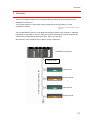
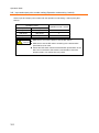
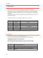
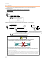
Anywire Corporation
R
AnyWire DB A20 Series
OMRON CJ1 PLC Interface
AFCJ01-D2
User’s Manual
Ver. 1.1 March 07, 2012
High speed transmission wiring saving
system by full-duplex transmission method
AnyWire DB A20 series
PMA-08503A
Cautionary Instructions
Cautions about this manual
1. Please deliver this manual to end users.
2. Read this manual thoroughly to understand the contents before operating this product.
3. This manual explains the details of functions equipped with this product, and does not
guarantee that the product will match a customer’s particular purpose.
4. Any reproduction or copying of this manual in whole or in part is expressly prohibited
without permission.
5. Information in this manual may be subject to change without notice in the future.
Warning displays
A “WARNING” indicates a potentially hazardous situation which, if not
!
WARNING
!
CAUTION
handled properly, could result in personal serious injury or death.
A “CAUTION” indicates a potentially hazardous situation which, if not
handled properly, could result in personal injury or property damage.
Safety precautions
!
WARNING
The AnyWire system does not include any control functions to ensure safety.
In any of the following cases, pay special attention to use with appropriate allowance for
ratings and functions and implement safety measures such as a fail-safe design and consult
us for:
(1) Applications which require a high degree of safety
・Applications predicted to have a great impact on human life or property
・Medical equipment, safety equipment, etc.
(2) When used in systems which require a higher degree of reliability
・Use in vehicle control, combustion control equipment, etc.
Make sure to turn off the system power before installation or replacement work.
Use the AnyWire system within the range of specifications and conditions defined in this
manual.
If current more than the rating or over-current by short-circuit continuously flows for a long
time in this unit, smoke or ignition may result. Install a safety circuit such as a fuse
externally.
i
!
CAUTION
Do not turn on the 24V power before completing wiring and connection of the entire
AnyWire system.
Use a regulated, 24V DC power supply for AnyWire system equipment.
Although the AnyWire system has high noise resistance, keep transmission cables and I/O
cables away from high-voltage and power cables.
Be careful to prevent any waste metal from entering inside of units or connector parts,
especially during wiring.
Miswiring may damage equipment. Pay attention to the cable length and layout in order to
prevent connectors and cables from being removed.
Do not solder a stranded wire to be connected to the terminal block; otherwise a contact
failure may occur.
If the wiring length of the power cable is long, voltage drops will occur and may cause
shortages of the power voltage of remote slave units. In that case, connect local power
supply units to ensure the specified voltage.
Install the product by avoiding the following places:
・ Where exposed to direct sunlight or the ambient operating temperature exceeds the range
of 0 C to 55 C
・ Where the operating relative humidity exceeds the range of 10% to 90% or condensation
occurs due to rapid temperature changes
・ Where there is corrosive or inflammable gas
・ Where subjected to direct vibration or shock
Tighten terminal screws securely to avoid malfunctions, etc.
When storing the product, avoid high temperature and humidity. (Ambient storage
temperature: -20 C to 75 C)
Incorporate the emergency stop circuit or interlock circuit for safety in an external circuit
other than the AnyWire system.
ii
CONTENTS
1
OVERVIEW.......................................................................................................................................................1-1
2
SPECIFICATIONS .........................................................................................................................................2-1
2.1.
GENERAL SPECIFICATIONS ........................................................................................................................................ 2-1
2.2.
PERFORMANCE SPECIFICATIONS ............................................................................................................................. 2-1
2.3.
COMPATIBLE CPUS .................................................................................................................................................... 2-2
2.4.
DIMENSIONAL OUTLINE DRAWING ............................................................................................................................ 2-3
2.5.
NAME OF EACH PART .................................................................................................................................................. 2-3
2.6.
UNIT ASSEMBLING ........................................................................................................................................................ 2-3
3
OPERATION MODE .....................................................................................................................................3-1
3.1.
MACHINE NO. SETTING .............................................................................................................................................. 3-1
3.2.
SPECIFICATION SELECTION (OPERATION MODE SETTING 2 SWITCH)........................................................... 3-1
3.3.
INPUT AND OUTPUT POINT NUMBER SETTING (OPERATION MODE SETTING 1 SWITCH)............................ 3-2
4
MEMORY MAP................................................................................................................................................4-1
5
MONITORING FUNCTION .........................................................................................................................5-1
5.1.
AUTOMATIC ADDRESS RECOGNITION ..................................................................................................................... 5-1
5.2.
MONITORING OPERATION .......................................................................................................................................... 5-1
6
ERROR STATUS ...........................................................................................................................................6-1
6.1.
ERROR FLAG ................................................................................................................................................................. 6-1
6.1.1.
6.2.
How to reset error status.....................................................................................................................................................6-2
ERROR ADDRESS ......................................................................................................................................................... 6-2
7
LED DISPLAY .................................................................................................................................................7-1
8
CONNECTION.................................................................................................................................................8-1
8.1.
9
TERMINATOR ................................................................................................................................................................. 8-2
TRANSMISSION REQUIRED TIME .......................................................................................................9-1
9.1.
IN THE CASE OF INPUT ................................................................................................................................................ 9-1
9.2.
IN THE CASE OF OUTPUT ............................................................................................................................................ 9-1
10
TROUBLESHOOTING ....................................................................................................................... 10-1
11
HISTORY OF CHANGES .................................................................................................................. 11-1
iii
Overview
1 Overview
This unit is a master interface for the AnyWire DB A20 series that can be mounted on the
OMRON CJ1 series PLC.
The AnyWire system is a high speed, highly reliable wiring saving system by unique
transmission method.
Note) AnyWire is a registered trademark of Anywire
Corporation.
The AnyWire DB A20 series is a full-duplex transmission system which supports, in particular,
high speed or long distance, and can input and output at a maximum 512 points respectively,
and transmit by transmission distances of 50m, 200m, 1km and 3km.
Disconnection can be detected even if branch wiring is carried out.
SYSMAC CJ series PLC
Input terminal
Output terminal
・・
AnyWire system transmission line
AFCJ01-D2
Input terminal
・・
Output terminal
1-1
Specifications
2 Specifications
2.1. General specifications
Operating ambient temperature
0 ~ +55° C
Operating ambient humidity
10 ~ 90% RH (No condensation)
Storage ambient humidity
Storage ambient temperature
-20° C ~ +75° C
Atmosphere
No corrosive or inflammable gas
Vibration proof
JIS C 0040 compliant
Noise proof
1200Vp-p (Pulse width 1μs)
2.2. Performance specifications
Transmission clock
Maximum
transmission
distance
Transmission cable
diameter
Transmission
method
Connection mode
Transmission
protocol
Error control
Number of
connecting IO points
Number of
connection nodes
RAS functions
2kHz
7.8kHz
31.3kHz
125kHz
3km
1km
200m
50m
0.9 ~ 1.25 mm
2
0.75 ~ 1.25 mm
Full-duplex cyclic method
Bus type (Multi drop method, T-branch method, tree branch method)
Dedicated protocol (AnyWireBus protocol)
Double collation system
Max. 1024 points (Input 512 points/Output 512 points)
Max. 128 nodes (Fine =1)
Transmission line disconnection position detecting function,
transmission line short-circuit detecting function, transmission power
drop detecting function
Multi-purpose 2 line cable/4 line cable (VCTF 0.75 ~ 1.25mm
Connection cable
2
2
rated
temperature 60° C)
2
Dedicated flat cable (0.75mm rated temperature 70° C)
2
Multi-purpose electric wire (0.75~1.25mm rated temperature 60° C)
2
(If transmission distance exceeds 1 km, VCTF 1.25mm or more)
Circuit: (Supply from CJ1 side) Voltage +5[V]±5%
Current 0.4[A]
Transmission line:
Power supply
Voltage 24V DC +15 ~ -10% (21.6~27.6V DC) ripple 0.5Vp-p or less
Current 0.2[A] (Load current is not included when 128 terminal units are
connected)
2-1
Specifications
■Maximum cycle time
(Unit: ms)
Operation mode
setting 1
Transmission clock
1
0
512points
(256 points×2)
1024 points
(512 points×2)
2kHz
138.4 max.
265.4 max.
7.8kHz
35.8 max.
68.5 max.
31.3kHz
9.0 max.
17.2 max.
125kHz
2.3 max.
4.3 max.
Caution: ① Transmission cycle time is a value between one cycle time and two cycle time.
② In order to ensure that input signal responds, issue input signal longer than two cycle time.
2.3. Compatible CPUs
This machine corresponds to a high function IO unit.
Installable CPUs are as follows.
CJ1H-CPU6□H-R
CJ1H-CPU6□H
CJ1G-CPU4□H
CJ1M-CPU1□
CJ1M-CPU1□-ETN
CJ1M-CPU2□
CJ2M-CPU3□
CJ2M-CPU1□
CJ2H-CPU6□-EIP
CJ2H-CPU6□
2-2
Specifications
2.4. Dimensional outline drawing
2.5. Name of each part
LED display
LED表示部
号機№設定
Machine No. setting
Operation mode setting 1
動作モード設定1
SETスイッチ
SET
switch
Operation
動作モード設定2
mode setting 2
モニタ接続コネクタ
Monitor connection
connector
Transmission
line connection connector
伝送線接続コネクタ
2.6. Unit assembling
After connecting the units, slide the upper and lower sliders until a clicking sound is heard to securely
lock.
Note that the functions may not be fulfilled unless locked.
Make sure to install the end cover attached to the CPU unit onto the rightmost unit. Unless the end
cover is installed, the CJ series will not operate properly.
2-3
Operation Mode
3 Operation Mode
3.1. Machine No. setting
Set the machine No. by the two rotary dip switches on this machine.
Since this machine occupies 4 machines by one unit, set the number within the range from “0”
to “92.”
For example, “04” to “07” are occupied when “04” is set. Do not set this number for other unit(s)
within this range.
3.2. Specification selection (Operation Mode setting 2 switch)
Select transmission distance etc., with the operation mode setting 2 switch (quad dip switch).
SW-1, 2
SW-3
Sets transmission distance by combination of ON/OFF with 1 and 2.
Setting switch for Bit mode operation. Use this in OFF.
SW-4
System reserve (Use this in OFF.)
ON on right side
*All the default switch positions are at “OFF.”
Operation mode 2 switch
Specification
1
2
2kHz 3km
OFF
OFF
7.8kHz 1km
OFF
ON
31.3kHz 200m
ON
OFF
125kHz 50m
ON
ON
Operation mode 2
switch
3
Operation
Specification
mode
Carry out double collation for data every bit (1
OFF
Bit mode
point).
Use Bit type for slave.
Turn OFF when using.
3-1
Operation Mode
3.3. Input and output point number setting (Operation mode setting 1 switch)
Select input and output point number with the operation mode setting 1 switch (rotary DIP
switch).
Operation mode
Operation mode 1 switch
Input
Output
512 points
512 points
0
256 points
256 points
1
512 points
512 points
2~F
!
CAUTION
Make sure to turn off the power to set the DIP switch.
Make sure to set the DIP switch according to the transmission
specification to be used.
Unless the DIP switch meets the transmission specification of the
slave unit connected to this machine, transmission cannot be
properly made, or a malfunction may result.
3-2
Memory Map
4 Memory Map
Offset address
Description
0 ~ 31
Output
32 ~ 63
System reserve
64
(32ch)
(32ch should not be used)
Error reset output
65 ~ 67
System reserve
(1 word)
(3ch should not be used )
200 ~ 231
Input
(32ch)
232 ~ 263
System reserve
264
Error flag input
265
Address response error slave unit number input
266 ~ 281
Error address
282 ~ 283
System reserve
(32ch should not be used )
(1ch)
(1ch)
(16ch)
(2ch should not be used)
(System reserve area should not be used.)
Data is mapped to the area after channel DM2000 is determined by the machine No.
The start channel No. is obtained by:
Start channel No.= 20000 + Offset address + Machine No. × 100
<Example> When the machine No. is “4”:
The start channel No. for output is from DM20400, by: 20000 + 0 + 4
The start channel No. for input is from DM20600, by: 20000 + 200 + 4
100.
100.
Correspondence between word address No. and data memory on AnyWireBus is
as follows.
Offset
address
ch No.
Output
Input
Bit No.
①
15 14 13 12 11 10 9
8
7
6
5
4
3
2
1
0
0
DM20400 15 14 13 12 11 10 9
8
7
6
5
4
3
2
1
0
1
DM20401 31 30 29 28 27 26 25 24 23 22 21 20 19 18 17 16
¦
¦
¦
31
DM20431
511 510 509 508 507 506 505 504 503 502 501 500 499 498 497 496
200
DM20600 15 14 13 12 11 10 9
201
DM20601 31 30 29 28 27 26 25 24 23 22 21 20 19 18 17 16
8
7
6
5
4
3
2
1
0
¦
¦
¦
231
DM20631
511 510 509 508 507 506 505 504 503 502 501 500 499 498 497 496
<Note> The ① column in the table shows an example when the machine No. is set to “4.”
Numbers from 1 to 511 in the table represent the address No. on the AnyWireBus.
4-1
Memory Map
Because the DM area cannot be handled by bit, it can be handled by relocating it to
internal auxiliary relay. Use block transmission instruction XFER for relocation.
Reference program for relocating input data
P_On
Always ON
XFER
&32
Transmission CH number
D20600 Transmission source lower CH No.
1200
Transmission destination lower CH No.
Reference program for relocating output data
P_On
Always ON
XFER
&32
Transmission CH number
1300
Transmission source lower CH No.
D20400 Transmission destination lower CH No.
No. of the internal auxiliary relay used here is a reference example.
Specify appropriate No. which is not used in other areas of the program.
In this example, input is mapped to 1200.00 through 1231.15, and output is mapped
to 1300.00 through 1331.15.
Note
Other than the above, this machine occupies an area of 40 channels after channel
2000 is determined by the machine No.
Do not use this area.
The start channel No. is obtained by:
Start channel No. = 2000 + Offset address + Machine No.
10
<Example> When the machine No. is “4”:
The start channel No. is from 2040, by: 2000 + 0 + 4
10.
Channel 2040 through 2079 are occupied by this machine.
4-2
Monitoring Function
5 Monitoring function
Overview
The slave units of the AnyWire system have their own addresses, and a slave unit which has an
address which was sent from this machine returns responses to the address, then detects for
disconnection and checks for existence of a slave unit.
This machine stores an address of the slave unit which is connected at that time by the automatic
address recognition operation (described later) into EEPROM. This information is stored even if
the power is turned off.
Then registered addresses are sequentially sent out, and if there is no response to them,
disconnection is displayed by the “ALM” LED, and an error flag is returned. In addition, addresses
of the slave units having errors can be known,
5.1. Automatic address recognition
Storing addresses of the connected slave units into EEPROM of this machine is called
“Automatic address recognition.”
〔Procedure〕
1 Check that all of the slave units operate normally.
2 Press the “SET” switch until the “SET” LED (Green) lights up.
3 If the “SET” LED lights up for a while and then turns off, storage of an address has been
completed.
〔Timing of automatic address recognition operation〕
・When all terminals are connected to the master and operation is started
・When some terminals are added
・When some terminals are removed
・When the address of a terminal is changed
!
Automatic address recognition operation cannot be made at the
CAUTION
time of an error in an AnyWire transmission line such as a shortcircuit, after the power is turned on, or for approximately 5
seconds after resetting.
If any disconnection error occurs during operation, do not perform
the automatic address recognition operation. Disconnection
information will be lost.
5.2. Monitoring operation
Addresses registered in this machine are sequentially sent out, and if there is no response to
them, disconnection is displayed by the “ALM” LED.
Bit 3 of the error flag is set to “1”.
This error information is retained until the power is turned off or the error is reset. (Refer to the
item of error status.)
5-1
Error Status
6 Error status
The status of a transmission line can be known by the error status of this machine.
The error status consists of a number of addresses from which an error flag and disconnection
are detected and the 16 error addresses. If any error by disconnection occurs, the applicable
slave unit can be known from the information of the number of addresses and information on an
error address.
If there are 16 or more error addresses, 16 addresses are displayed sequentially in the order of
the most recent number.
Correspondence between error information and data memory is as follows.
Offset address
② ch No.
Description
264
DM20664
Error flag
265
DM20665
Number of error address
266
DM20666
Error address 1
267
DM20667
Error address 2
268
DM20668
Error address 3
¦
¦
¦
280
DM20680
Error address 15
281
DM20681
Error address 16
<Note> The ② column in the table shows an example when the machine No. is set to “4.”
6.1. Error flag
An error flag can be read by setting the offset address to 264.
The number of error addresses can be read by setting the offset address to 265.
This status can also be displayed by the “ALM” LED.
The associated bit becomes “1” if any error occurs.
Bit 3 is retained until the power is turned off, or an error is reset (described later).
Bit 0, 1 and 2 become “0” when an error status is cancelled. They are not retained.
Bit 0
Short-circuit between D and G
Bit 1
Short-circuit between D and P
Bit 2
24V is not supplied, or voltage is low.
Bit 3
Disconnected. Or slave unit failed, or power is not supplied.
Bit 4~15
6-1
Reserved
Error Status
6.1.1.
How to reset error status
Write “1” into the data memory area of the offset address 64.
If an error such as disconnection is eliminated, the disconnection flag is reset to “0” and the
number of error addresses is also reset to “0.”
Unless an error condition is eliminated, the number of error flags and error address are set, and
the error address is set again.
An error is also cleared by turning on power again.
Offset address
② Ch No.
Description
64
DM20464
Error reset output
<Note> The ② column in the table shows an example when the machine No. is set to “4.”
6.2. Error address
When disconnection or any error in the slave unit occurs, up to 16 error addresses are written
into the offset addresses 266 to 281. (See 4 Memory map.)
Values written are classified according to the following table.
Hexadecimal display address
Description
000~1FF
Address of output slave
200~3FF
Address of input slave
The lower 2 digits represent the address set for the slave unit.
The uppermost digit represents the type of slave unit.
This value is retained until the error is reset or the power is turned OFF.
6-2
LED Display
7 LED Display
LED indicating the status of this unit
LED
Name
Color
RUN
Operating
Green
ERC
Unit error
Red
ERH
CPU unit error
Red
Indication
Lit
Unlit
Lit
Unlit
Lit
Unlit
This unit is operating.
This unit is in a stopped state.
This unit has an error.
This unit is normal.
There is an error caused by the CPU unit.
The CPU unit is normal.
Main causes of ERC LED and ERH LED lighting
Causes of ERC LED
This unit is not recognized as a high-performance I/O unit.
lighting
Hardware check error
The machine No. is not set within the range of 00 to 92.
Double setting of a machine No.
Causes of ERH LED
No units registered in the I/O table.
lighting
I/O bus error
CPU watchdog timer error
LED indicating AnyWireBus status
LED
LINK
Name
Transmission
display
Color
Green
address
recognition
Flashing
This unit is operating.
Unlit
This unit has an error.
Lit
Display on
SET
Indication
Green
operation
In
Unlit
display
Flashing
Writing in EEPROM
Disconnection of AnyWireBus D, G.
Slow flashing
Red
Short-circuit between D and G, or
short-circuit between D and 24V.
*2
Quick flashing
Unlit
24V is not supplied, or voltage is low.
On normal transmission.
*1 : “Slow flashing” is flashing of approximately 1 second period.
*2 : “Quick flashing” is flashing of approximately 0.2 seconds period.
In profile rewrite mode, ERC and ERH are displayed as follows:
7-1
LED
Name
Color
ERC
Unit error
Red
ERH
CPU unit error
Red
recognition
In normal transmission.
*1
ALM
address
operation.
Lit
Alarm
automatic
Indication
Lit
Flashing
Lit
Normal termination
Abnormal termination
Profile rewrite mode display
Connection
8 Connection
Use 2-wire or 4-wire VCTF, VCT (rated temperature 60° C) cable or dedicated flat cable (FK4075-100:rated temperature 70° C).
See page 2-1 for wire diameter.
For the power line, make connection using a wire diameter in consideration of voltage drop.
AnyWireBus connecting terminal of this machine is provided with quick detachable connector
terminals.
Model
: MC1.5/5-STF-3.81 (manufactured by PHOENIX CONTACT)
Connectable cable
: 0.14 ~ 1.5mm (AWG28 ~ 16)
Tightening torque
: 0.22 ~ 0.25N・m
2
D
Transmission cable
G
Transmission cable
24V
0V
Connect a regulated 24V DC power supply.
Power supply with capacity of current necessary for load and
slave unit and +0.2A or more
Connected to neutral point of noise filter.
Ground when there is a malfunction due to 24V based power
LG
noise.
In this case, ground to the function grounding terminal of
PLC at one point.
Connect D and G with D and G of the slave unit respectively.
(Refer to the instruction manual of each unit.)
!
MONITOR connector
CAUTION
Connector for connecting maintenance monitor.
Connect nothing.
8-1
Connection
8.1. Terminator
In order to ensure more stable transmission quality, connect a terminator (AT2) to the
transmission line end.
This terminator is a module to stabilize wave form, and has polarity.
Connect properly.
■Connection of terminator
Basic
Nece
Connect one AT2 to the foremost end for one master.
Transmission distance 50m (Total extension)
200m ( 〃 )
1km ( 〃 )
3km ( 〃 )
Common to the respective transmission speed.
■Branch of transmission line (Transmission distance 1km specification)
■Total extension
[Example of connection]
Basic
Fixed one
piece
Branch 200m
A
Main line 500m
B
Branch 300m
Req.
Connect one AT2 to the terminal end for locations of a branch length
200m or longer. If there are three or more locations of a branch length
200m or longer, contact us.
!
“Total extension” of transmission distance referred to in the AnyWire
DB A20 series means A+B. When branching, make sure not to
exceed the maximum transmission distance (total extension) set by
the system.
CAUTION
Do not send some transmission lines (D, G) in a multicore cable all together.
If sent all together, the equipment will malfunction due to crosstalk.
D
G
D
D
G
D
G
G
2
The transmission cable shall be 0.75 to 1.25mm in wire diameter.
The lower limit of the power voltage is down to 21.6V, however, the voltage shall not be
below 24V in the master.
Watch out for voltage drop by cable. Voltage drop will cause the equipment to malfunction.
If the voltage drops significantly, supply power on the terminal side. (local power supply)
Do not solder wires connected to the connector terminal. The wire may loosen, resulting
in a contact failure.
8-2
Transmission Required Time
9 Transmission Required Time
9.1. In the case of input
Because the master side does not update data (double collation) unless the same data
consecutively continues two times, the transmission cycle time requires transmission time of
a minimum one cycle time and maximum two cycle time. Signals of two cycle times or less
may not be captured depending on the timing. Therefore, in order to ensure a response,
provide an input signal of two cycle times or longer.
Minimum transmission cycle time
Case of minimum
transmission cycle
1 cycle time
Input data update
Change in input data
Maximum transmission cycle time
2 cycle times
Case of maximum
transmission cycle
Change in input data
Input data update
9.2. In the case of output
Because the slave unit side performs double collation, it requires transmission time of a
minimum one cycle time and maximum two cycle times similar to the case of input.
Terminology
Transmission cycle time:
Repeated transmission time of actual data
transmitted
Maximum transmission delay time:
Processing time on master side+Transmission
cycle time+Signal delay time on slave side
Response delay time is as shown in the following diagram.
Input and output
equipment
Input
Output
①Input equipment response time
AnyWire
system
⑨Output equipment response time
⑧Slave side signal delay time
②Slave side signal delay time
③Transmission cycle time
⑦Transmission cycle time
④Master side processing time
⑥Master side processing time
Maximum transmission delay time
Maximum transmission delay time
PLC
⑤PLC processing time
9-1
Troubleshooting
10 Troubleshooting
Check the following at the start.
(1)
The “RDY” lamps for all units of the equipment shall light up.
(2)
The “LINK” lamps for all units of the equipment shall flash.
(3)
The power voltages for all units of the equipment shall be in a range from 21.6 to 27.6V.
(4)
Wiring and connection shall be secured.
(5)
Address setting shall be correct, and not be duplicated.
Checklist by symptom
Symptom
Check Item
AFCJ01-D2 side
MODE switch is correctly set.
I/O configuration set with the MODE switch is consistent with I/O
No. specified by the software.
Data cannot be input and
output
Slave unit side
Power is supplied to the slave unit.
Address of the slave unit is correctly set.
Slave unit of the same specification as that of AFCJ01-D2 (such
as transmission clock and number of input and output) is used.
D, G lines are not disconnected.
ALM LED (Red) lights up
Address automatic recognition operation is correctly performed.
Screws on the terminal blocks are not loosened.
ALM LED (Red) slowly
D, G lines are not short-circuited.
flashes
D does not contact 24V
ALM LED (Red) quickly
flashes
ERC LED lights up
Voltage of 24V DC power supplied to AFCJ01-D2 is normal.
Securely connected to the adjacent unit.
Setting of machine No. is in a range from 0 to 92.
ERH LED lights up
Machine No. the same as that of the other unit is not set.
I/O table is set.
10-1
ERR/ALM LED of CPU
The end cover attached to the CPU is installed to the rightmost
lights up
unit.
History of Change
11 History of Changes
Version
Date
1.0
January 6, 2005
1.1
March 7, 2012
Change Description
Formal version released
Cable rate temperature additionally described, contact
information changed
11-1
Anywire Corporation
URL: http://www.anywire.jp
■ Headquarters / West Japan Office
8-1, Shimoinden, Inouchi, Nagaokakyo-shi, Kyoto 617-0813 JAPAN
TEL: (+81) 75-956-1611 FAX: (+81) 75-956-1613
■ East Japan Office
Shin-Koei Bldg. 6F, 47, Kandakonya-cho, Chiyoda-ku, Tokyo 101-0035 JAPAN
TEL: (+81) 3-5209-5711 FAX: (+81) 3-5209-5713
■ Chubu Office
5-1-14 Yadaminami, Higashi-ku, Nagoya-shi, Aichi 453-0014 JAPAN
TEL: (+81) 52-452-8711 FAX: (+81) 52-452-8713
■ Kyushu Office
No. 6 Myojyo Bldg. 7F, 1-15-2 Tenjin, Chuo-ku, Fukuoka-shi, Fukuoka 830-0059 JAPAN
TEL: (+81) 942-46-9811 FAX: (+81) 942-46-9813
■ Kyoto Factory
19-2, Umatate, Kamiueno-cho, Muko-shi, Kyoto 617-0006 JAPAN
TEL: (+81) 75-922-1911 FAX: (+81) 75-922-1913