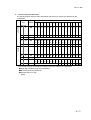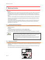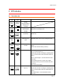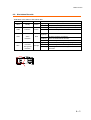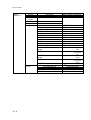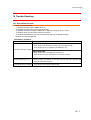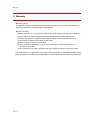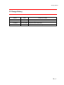
1
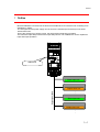
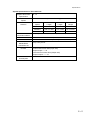
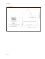
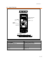
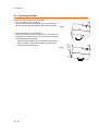
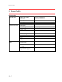
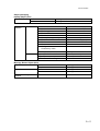
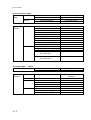
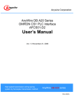
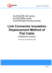
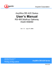
Anywire Corporation
Open Terminal series
Device Net Bit Distributed I/O Terminal
AB023-D1
User’s Manual
Version 1.2 March 02, 2006
Bit Control & Information Transmission
Sho-haisen system
Open Terminal seires
ab023d1umb
Precautions
Precautions for this manual
1.
2.
3.
4.
5.
Please deliver this User’s Manual to the end user.
Please read this User’s Manual carefully and understand the details of the product well
before you start using it.
This manual explains the details of the functions including in the product, but does not
guarantee the compatibility to user’s own purpose.
It is prohibited to reprint or reproduce a part of this manual or all without permission.
The contents of this manual may be changed without notice.
The indications of warnings and cautions for safe and correct use
Indicates a potentially hazardous situation, which, if not avoided, could result in
death or serious injury.
Indicates a potentially hazardous situation, which, if not avoided, could cause
personal injury or damage.
The precautions for using the system under safety condition
◆ AnyWire System is not intended to have control functions for securing safety.
◆ In the following cases, special consideration is necessary for the usage
sufficient for ratings and functions, and necessary for safeguard such as
fail-safe function. And also, please contact our company.
(1) actions requiring higher safety
1- Applications expected to have a great influence on life or property
1- Medical equipment, or safety devices
(2) actions requiring higher reliability of system
1- Applications for vehicle control or burning control system
◆Be sure to turn the power off before installation or replacement.
◆ Be sure to use AnyWire System within the specifications and conditions
prescribed in this manual.
i
◆ Be sure not to turn on the 24V power before completing wiring and
connecting in AnyWire System.
◆ Use a regulated power supply of 24V DC. Non-regulated power supply may
cause a trouble to the system.
◆ Keep transmission cables and I/O cables away from high-voltage and power
cables, though the AnyWire System has high noise margin.
◆ Be careful not to allow metal bits into the unit, the connectors or the terminal
blocks, especially when wiring.
◆ Mis-wiring may cause failure. Consider the length and installation of cable
wiring to keep connectors and cables from disconnecting or excessive
distortion.
◆ Never solder the stranded wire to be connected with the terminal block,
otherwise causing a defective contact.
◆ In case of long cable length of power line along the transmission lines, large
voltage drops will occur and may cause voltage shortage for the distant
Slave Units. In that circumstance, connect the local power supply units so
that the prescribed voltage is secured at each local Slave Unit.
◆ Be careful of the following items about installation environment.
· No exposing directly to the sunlight and ambient temperature is 0 to +55 ˚C.
· Operating relative humidity is 10 to 90 % and no dew condensation by
sudden temperature change
· No corrosive or inflammable gases
· No direct vibration or impact
◆ Fasten terminal screws securely to avoid malfunction.
◆ In case of storage of the product, keep away from high temperature and
high humidity. (Storage temperature is –20 to 75˚C.)
◆ When the emergency stop circuit or the interlock circuit for safety are
arranged, provide these circuits outside the AnyWire System.
ii
INDEX
1
OUTLINE ................................................................
................................................................................................
................................................................................................
.........................................................................................
.........................................................1
......................... 1-1
2
SPECIFICATION ................................................................
................................................................................................
................................................................................................
..........................................................................
..........................................2
.......... 2-1
2.1.
GENERAL SPECIFICATIONS ............................................................................................................................................ 2-1
2.2.
CAPABILITY SPECIFICATIONS ........................................................................................................................................ 2-1
2.3.
DIMENSION ........................................................................................................................................................................... 2-3
2.4.
NAME OF EACH PART ....................................................................................................................................................... 2-4
2.5.
DETACHING TO DIN RAIL ................................................................................................................................................ 2-5
3
SWITCH SETTING ................................................................
................................................................................................
................................................................................................
......................................................................
......................................3
...... 3-1
DEVICENET SIDE ................................................................................................................................................................. 3-1
3.1.
3.1.1.
Node Address Setting ..........................................................................................................................................................................3-1
3.1.2.
Communication speed setting...........................................................................................................................................................3-1
3.2.
SHO-HAISEN BUS SIDE ........................................................................................................................................................ 3-1
3.2.1.
4
Specification Selection (MODE Switch).......................................................................................................................................3-1
MEMORY MAP ................................................................
................................................................................................
................................................................................................
................................................................................
................................................4
................ 4-1
4.1.1.
5
Memory allocation example................................................................................................................................................................4-2
MONITORING FUNCTION ................................................................
................................................................................................
...........................................................................................
...........................................................5
........................... 5-1
5.1.
AUTOMATIC ADDRESS RECOGNITION ........................................................................................................................ 5-1
5.2.
MONITORING OPERATION ............................................................................................................................................... 5-1
6
LED INDICATION................................
INDICATION................................................................
................................................................................................
................................................................................................
............................................................................
............................................6
............ 6-1
6.1.
DEVICENET SIDE.................................................................................................................................................................... 6-1
6.2.
SHO-HAISEN BUS SIDE ........................................................................................................................................................ 6-3
7
CONNECTIONS................................
CONNECTIONS................................................................
................................................................................................
................................................................................................
...............................................................................
...............................................7
............... 7-1
8
TIME REQUIRED FOR TRANSMISSION
TRANSMISSION ................................................................
................................................................................................
.................................................................
................................. 8-1
8.1.
INPUT ....................................................................................................................................................................................... 8-1
8.2.
OUTPUT ................................................................................................................................................................................. 8-1
9
DEVICE PROFILE................................
PROFILE ................................................................
................................................................................................
................................................................................................
...........................................................................
...........................................9
........... 9-1
10
10.1.
TROUBLE SHOOTING ................................................................
................................................................................................
................................................................................................
.................................................................
................................. 10-
10-1
SHO-HAISEN BUS SIDE ...................................................................................................................................................10-1
11
WARRANTY................................
WARRANTY................................................................
................................................................................................
................................................................................................
...............................................................................
............................................... 11-
11-1
12
CHANGE HISTORY ................................................................
................................................................................................
................................................................................................
................................................................ 12-
12-1
iii
Outline
1 Outline
Bit decentralization I/O terminal is the best for DeviceNet when I/O under the link controlling more
distribution in detail.
The I/O signal and the power supply can be sent to the terminal (D-I/O terminal) in two wires
transmission lines.
Even if the divergence of wiring is done, the disconnection detection is possible.
The maximum input 256 points and the output 256 points a unit of AB023-D1 can be capable for
input and output operation.
NODE ADDRESS
X10
X1
MONITOR
SET
1 2 123456
34
MODE
ON
Open Terminal
AB023-D1
24V
24V
LG
DP
0V
DP
DN
DN
Slave input unit
AnyWireBus Bitty
・・
Output slave unit
Slave input unit
Output slave unit
・・
1-1
Specification
Specification
2
2.1. General Specifications
Ambient operating
0℃ ... +55℃
Temperature
Storage
- 20℃ ... +75℃
Temperature
Storage Humidity
Ambient
10% ... 90%RH (No condensation)
No corrosive or flammable gas
Atmosphere
2.2.
Capability Specifications
System Specifications on Sho-haisen Bus side
Transmission Clock
Transmission Mode
Connection Form
Transmission
Protocol
Number of
Connection I/O
points
Number of the
Connection points
Transmission Cycle
Time
(1 cycle time value)
Connection Cable
Max. Transmission
Distance
Supply Maximum
Current of
Transmission
Power Supply
Voltage
Circuit Current
Consumption
Range of Voltage
during use Slaves
Supply Voltage of
Slave Load
2-1
28.7KHz
Total frame cyclic method with DC power supply on common wire
Bus Form (A Multi-drop Method, a T-branch Method, a Tree Branch
Method)
Dedicated protocol (AnyWireBus Bitty protocol)
512 points (IN: 256 points OUT: 256 points)
Up to 128 units (Changed by consumption current of each unit)
10.2ms/IO 512 points
Note) The transmission cycle time reaches the value between 1 to 2
cycle times.
General-purpose 2-wire cable (0.75 mm² ... 2.0 mm²)
During operation of rated 24 V: 50m (1.25 mm² electric cable)
Condition: 2 A load current, a relay drive ability distance
2A
DC26.4V (DC24V rated supply)
0.2A
Power source supply is unnecessary. (supplied from the
transmission line)
Power source supply is unnecessary. (supplied from the
transmission line)
Specification
System Specification on DeviceNet side
Adaptive DeviceNet
Specification
Communication
Speed
Communication
Distance
Max. Number of
Connection Nodes
Error Control
Ver.1.2
500K/250K/125Kbit/s (Automatic Tracking)
Communication
Max. Network
Branch
Total Branch
Speed
Length
Length
Length
500Kbit/s
100 m or less
6 m or less
39 m or less
250Kbit/s
250 m or less
6 m or less
78 m or less
125Kbit/s
500 m or less
6 m or less
156 m or less
64 units (Slaves can be connected up to 63 units.)
CRC error, node address overlap check, Check the scan list
Connection Connector MVSTBW2.5/5-STF-5.08AUM (made by Phoenix contact)
Predefined
Group 2 only server
Master/Slave
Connection set
I/O Size
Produced Connection Size (Input size)
256-point input―― 34
Consumed Connection Size (Output size)
256-point output ―― 34
Max. Current
Consumption
40mA
2-2
Specification
2.3.
Dimension
* is a size when opened the cover.
(86)
** is a size when installed the CIN rail.
Reference value is in parentheses.
2-3
Specification
2.4.
Name of Each Part
DeviceNet接続端子
NODE ADDRESS
設定スイッチ
NODE ADDRESS
モニタ接続
ポート
X10
SETスイッチ
X1
MONITOR
MODE
設定スイッチ
SET
MODE
ON
12 3 4
Open Terminal
表示LED
24V
24V
LG
DP
0V
DP
DN
DN
Bitty接続端子
24V
24V
LG
DP
0V
DP
DN
DN
Japanese
English
DeviceNet接続端子
DeviceNet Connection Terminal
MODE ADDRESS 設定スイッチ
MODE ADDRESS Setting Switch
モニタ接続ポート
Monitor Connection Port
MODE 設定スイッチ
MODE Setting Switch
SETスイッチ
SET Switch
表示LED
Indication LED
Bitty接続端子
Bitty Connection Terminal
2-4
Specification
2.5. Detaching to DIN Rail
Please use and install this unit on the DIN.
1. How to install this unit on DIN rail
[1] A fixed pick upper in the bottom is put on the DIN rail.
[2] This device is pressed against the DIN rail and sets it.
Install
取り付け
2. How to detach this unit from DIN rail
The hook comes off from the rail when a minus driver is
defeated to the difference all-in in the hook and the driver
is defeated to this device side.
The main body fixation pick side is detached, and under
②
such a condition, please lift and detach the main body
hook side to the starting point.
②
Detach
取り外し
①
2-5
①
Switch Setting
3 Switch Setting
3.1. DeviceNet side
3.1.1.
Node Address Setting
The node address is set by the node address setting switch (NODE ADDRESS).
Node address ranges differ depending on the Master unit used.
Communication is not succeed if the node address overlaps with other nodes.
“NODE ADDRESS” Switch
NODE ADDRESS
3.1.2.
×10
×1
0
0
0
1
0
1
2
0
2
3
0
3
・
・
・
62
6
2
63
6
3
NODE ADDRESS
X10
X1
MONITOR
SET
1 2 123456
34
MODE
ON
Open Terminal
Communication speed setting
Communication speed follows the Master by the automatic tracking function.
3.2. Sho-haisen Bus side
3.2.1.
Specification Selection (MODE Switch)
The transmission distance can be selected using MODE switch (The following “SW-*” responds to
labels 1-4).
SW-2,1
Transmission number (occupied byte number) can be set by the combination of
ON/OFF of 2 and 1.
SW-3
Reserved. Use when the setting is OFF.
SW-4
Reserved. Use when the setting is ON.
SW
1
2
NODE ADDRESS
Number of
Number of DeviceNet
transmission points
occupied bytes
Input
Output
Total
Input
Output
OFF OFF
256
256
512
34
34
OFF
ON
128
128
256
18
18
ON
OFF
64
64
128
10
10
ON
ON
256
256
512
34
34
X10
MONITOR
SET
1 2 123456
34
MODE
ON
Before setting the DIP switches, be sure to turn off the power.
Setting changes when applying current are not valid.
3-1
X1
Open Terminal
Memory Map
4
Memory Map
Offset byte address of input on the DeviceNet Master side is as given in the table below.
Number of
transmission
points
Input area
Alarm flag
area
The area in which the
number of abnormal
addresses is stored
Number of input
occupied bytes
256 points
0-31
32
33
34
128 points
0-15
16
17
18
64 points
0-7
8
9
10
When an error occurs, the corresponding bit in alarm flag area is set to “on”.
Bit 0 is set to "0" if the error condition is canceled. They do not retain their values.
Bit 1 retains until the power turns off or the error rests.
Bit 0
Short between DP and DN
Bit 1
Set to “1” in the event of an address reply error. Possible causes include
a disconnection, the terminal being faulty, and power not being supplied.
Bit 2-7
Spare
In the area in which the number of abnormal addresses is stored, the number of abnormal IDs is input in
binary.
Bit 0-7
The number of abnormal IDs
Offset byte address of output on the DeviceNet Master side is as given in the table below.
Number of
transmission
points
Output area
Command
area 1
Command area 2
Number of output
occupied bytes
256 points
0-31
32
33
34
128 points
0-15
16
17
18
64 points
0-7
8
9
10
Command area 1
Bit 0
Setting the error reset bit from "0" to "1" causes the address reply error
information to be cleared.
Bit 1-7
Spare
The slave response alarm reset output may fail to reset alarm information when the
alarm is remedied after the slave unit is detached and attached with the power on or
there is a temporary line disconnection due to poor contact or some other cause.
In this case, turn the power off and then back on.
The command area 2 is a reserved area.
4-1
Memory Map
4.1.1.
Memory allocation example
This section describes the DeviceNet Master (CS1W-DRM21, CJ1W-DRM21) made by
OMRON for SYSMAC CS/CJ series.
1. The use of fixed allocation area 1
If using fixed allocation areas, 17 node addresses from the starting node address to the
starting address +16 are occupied.
bit №
Offset
Byte
CH No
15 14 13 12 11 10
9
8
7
6
5
4
3
2
1
0
9
8
7
6
5
4
3
2
1
0
Address
OUTPUT
1
0
3200
15 14 13 12 11 10
3
2
3201
31 30 29 28 27 26 25 24 23 22 21 20 19 18 17 16
¦
¦
¦
¦
31
30
3215
25 25 25 25 25 25 24 24 24 24 24 24 24 24 24 240
33
32
3216
- - - - - - - - - - - - - - -
A
1
0
3300
15 14 13 12 11 10
0
3
2
3301
31 30 29 28 27 26 25 24 23 22 21 20 19 18 17 16
¦
¦
¦
¦
31
30
3315
25 25 25 25 25 25 24 24 24 24 24 24 24 24 24 240
5
INPUT
5
33
32
3316
4
4
3
3
2
2
1
1
0
0
9
9
9
Number of abnormal IDs
8
7
8
8
7
7
6
6
6
5
5
5
4
4
4
3
3
3
C: Address reply error flag
-:Spare
4-2
2
1
1
2
1
- - - - - -
C
The number between 0 and 255 in the figure shows the address on AnyWireBus.
A: Clear flag of address reply error information
B: Short flag between DP and DN.
2
B
Memory Map
2. The use of Use-set allocation
The following figure shows if output from 50CH and input from 100CH are allocated by the
configurator.
Offset
Byte
bit No
CH No
15 14 13 12 11 10
9
8
7
6
5
4
3
2
1
0
9
8
7
6
5
4
3
2
1
0
address
OUTPUT
1
0
500
15 14 13 12 11 10
3
2
501
31 30 29 28 27 26 25 24 23 22 21 20 19 18 17 16
¦
¦
¦
¦
31
30
515
25 25 25 25 25 25 24 24 24 24 24 24 24 24 24 240
5
4
3
2
1
0
9
8
7
6
5
4
3
2
1
INPUT
33
32
516
- - - - - - - - - - - - - - -
A
1
0
100
15 14 13 12 11 10
0
3
2
101
31 30 29 28 27 26 25 24 23 22 21 20 19 18 17 16
¦
¦
¦
¦
31
30
115
25 25 25 25 25 25 24 24 24 24 24 24 24 24 24 240
5
33
32
116
4
3
2
1
0
9
9
Number of abnormal IDs
8
8
7
7
6
6
5
5
4
4
3
3
2
1
2
1
- - - - - -
C
B
The number between 0 and 255 in the figure shows the address on AnyWireBus
A:Clear flag of address reply error information
B:Short flag between DP and DN
C:Address reply error flag
-:Spare
4-3
Monitoring Function
5 Monitoring Function
Overview
Each I/O terminal of Sho-haisen Bus series has unique address, and returns back the reply when
the address sent from this device is correspondent to its own address number. The device, by
checking the response signals, detects wire disconnection and confirms that the I/O terminal is in
place.
This device, with its address auto-recognizing operation (description given later), memorizes the
addresses of the connected I/O terminal into EEPROM. This information will remain in storage
even if power is turned off.
Then the device sends out the registered addresses in sequence through the transmission line,
and if there is no response to these, it will recognize this as wire disconnection, which will be
displayed by the "ALM" LED.
5.1.
Automatic Address Recognition
Storing the addresses of the connected I/O terminals in this unit's EEPROM is called "automatic
address recognition".
Procedure
1. Check that all the slave units are in the normal operation status.
2. Hold down the "SET" switch until the "SET" LED (orange) comes on.
3. When the "SET LED" rapidly blinks and then goes off, the storage of the address is complete.
During automatic address recognition, input/output operation may not work. Be sure to
carry on automatic address recognition, when the program of PLC stops or in the
condition that there is no interference in the movement of the machine.
On abnormal status in the Sho-haisen Bus such as short-circuit, or for five seconds
after turning on the power or resetting, automatic address recognition can not be
operated.
5.2.
Monitoring Operation
The unit sends the registered addresses sequentially. If no response is returned to any of these
addresses, the unit regards the corresponding I/O terminal as being disconnected and turns on the
"ALM" LED.
This alarm information is retained until the power is turned off or the information is reset by the
slave response alarm reset output. (Refer to the “LED indication”)
NODE ADDRESS
X10
X1
MONITOR
SET
5-1
12 123456
34
MODE
ON
Open Terminal
LED Indication
6 LED Indication
6.1. DeviceNet side
MS
LED
NS
LED
Status
Lights up
Lights up
During
(Green)
(Green)
communication of
Causes and actions
remote I/O or
message
Lights up
Goes out
(Green)
During check of
node address
Waiting for overlap-checking completion of node
addresses in the Master unit
overlap
Lights up
Flashing
Waiting for
Waiting for the connection established in the
(Green)
(Green)
connection
Master unit
Lights up
Goes out
Watchdog timer
(Red)
Watchdog timer error occurs. Change this unit.
error
Lights up
Lights up
Node address
(Green)
(Red)
overlap
Node addresses in this unit overlap with other
slaves.
Restart the unit after setting correctly.
Lights up
Lights up
(Green)
(Red)
Bus-off detection
Bus-off (communication cancels caused by data
error occurred frequency)
Restart this unit after checking the following items.
Is the communication speed of Master/slave the
same?
Are the cable lengths (trunk lines/branch lines)
correctly?
Is there disconnection or slack of the cable?
Is there terminating resistance at the end of the
trunk line?
Are there a lot of noises
Lights up
Flashing
Communication
(Green)
(Red)
time out
The connection to the Master is timeout.
Restart this unit after checking the following items.
Is the communication speed of master/slave the
same?
Are cable lengths (trunk lines/branch lines)
correctly?
6-1
LED Indication
Is there disconnection or slack of the cable?
Is there the terminating resistance at the end of the
trunk line?
Are there a lot of noises?
24V
6-2
LED Indication
6.2. Sho-haisen Bus side
●Indication of the status of Sho-haisen Bus
Indication
Function
Color
RDY
Ready
Green
Transmission
LINK
ALM
SET
Indication
Alarm
Indication
Green
Meaning
Lights up
This unit is in operation.
Goes out
The power is not supplied, or this unit is faulty.
Flashing
Data is being transmitted normally.
Goes out
This unit is faulty.
Lights up
Red
The transmission line DP or DN is disconnected, or
the slave unit does not respond.
Flashing
Short circuit between DP and DN
Goes out
Data is being transmitted normally.
Address
Lights up
Automatic address recognition is in progress.
Automatic
Goes out
Data is being transmitted normally.
Flashing
The recognized address is being written to
Recognized
Indication
Orange
EEPROM.
24V
6-3
Connections
7 Connections
DeviceNet side
This connector terminal is an easy desorption.
Model: MVSTBW2.5/5-STF-5.08AUM (a product made by Phoenix Contact)
Connectable electric wire: 0.2n - 2.5m㎡ (AWG24 - 12)
Clamping torque: 0.5 - 0.6N-m
The sticker with a connector corresponds to the cable color. It is possible to check by the color of
cables and units whether the wiring is collect or not.
Terminal
Signal Type
Line
Communication power
(Red)
Name
V+
Color
supply cable (+ side)
CAN H
Communication data
White
High side
DRAIN
Shield
CAN L
Communication data
-
Blue
Low side
V-
Communication power
(Black)
supply cable side (- side)
Refer to the user's manual of each DeviceNet Master for connection method.
When detaching “DeviceNet side connectors” and “AnyWireBus side connectors”, check to see that
the fixation screws on both ends are loosened (unplugged from the sockets) before pulling them off.
The devices could be damaged if the connectors are forcedly pulled off while they are still locked.
When installing the device, check to see that there will be no short-circuits due to feasings or cast-off
of the wires and securely tighten the screws at the both ends. (Tightening torque 0.5N-m)
Fixation Screw
7-1
Connections
Sho-haisen Bus side
An eight-pole M3 screw terminal block is on this side.
Connectable wire: AWG22 - AWG14
Tightening torque: 0.8N-m
Connect a 24 VDC stabilized power supply.
24V
Its capacity of electric current must be +2 A or more, which is
0V
necessary for the load and slave unit.
Transmission line (+ side)
DP
Transmission line (- side)
DN
Connected to the neutral point of the noise filter.
LG
Ground it in the event of a malfunction caused by 24-V power
noise.
In that case, the grounding work of Class D rating must be
conducted individually.
Connect a slave unit of the Bitty Series. DB series slave unit cannot be connected.
Connect the DP and DN terminals to their counterparts on the slave unit, respectively. (Refer to
the user's manual of each unit in use.)
MONITOR Connector
This connector is used to connect a maintenance monitor.
Do not connect the Uniwire system's real-time monitor RM-120.
NODE ADDRESS
X10
X1
MONITOR
SET
12 123456
34
MODE
ON
7-2
Open Terminal
Connections
* Do not use plural transmission lines (DP, DN) with many cable lines together.
It has the possibility that the equipment operates faultily due to the cross talk when it is
transmitted together.
2
* Set the diameter of the transmission line at more than 1.25 mm .
* Connect between transmission lines (DP, DN) correctly.
* Be careful of the voltage drop by the cable. Equipment operates faultily due to the voltage drop.
Supply a power supply in the terminal side when a voltage drop is big. (A local power supply)
* A line to connect to the connector terminal isn't to do solder. A line causes a looseness contact
defect.
7.1. Terminator
Connect one AT0 terminator to the far end of the Sho-haisen bus line.
Otherwise, the line may not be able to transmit data normally.
AB023-D1
Slave Terminal
Slave Terminal
AT0
7-3
Time Required for Transmission
8 Time Required for Transmission
8.1. Input
Since the input area data is not updated unless the same data is received twice consecutively on
Sho-haisen bus side of the unit (double checking), the transmission time must be at least 1-cycle
time or up to 2-cycle time. The unit may not be able to capture a signal shorter than the 2-cycle
time depending on the timing. To ensure a response is returned, therefore, a signal longer than
the 2-cycle time must be input.
The minimum Cycle Time
One cycle time
Case of the
Minimum Cycle
Time
Renewal of input data
Change of input data
The maximum Cycle Time
Two Cycle Times
Case of the
Maximum Cycle
Time
Change of input data
8.2.
Renewal of input data
Output
Since double collation performed by the slave unit side, the transmission time of a minimum of
one cycle time and a maximum of two cycles time is needed like the case of an input.
Term
Cycle time: Repetition transmission time of the actual data transmitted.
Maximum transmission delay time: Processing time by the side of a gateway
+ Refresh time + Slave side Signal delay time
Response delay time becomes as it is shown in the following figure.
Input/output
devices
Input
Output
[1] Input apparatus response time
AnyWire
System
[9] Output apparatus response time
[8] Slave side signal delay time
[2] Slave side signal delay time
[3] Transmission cycle time
[7] Transmission cycle time
[4] Gateway side processing time
DeviceNet
System
[6] Gateway side processing time
The maximum transmission delay time
The maximum transmission delay time
[5]DeviceNet System
Processing time
8-1
Device Profile
9 Device Profile
Device profile
General Data
Physical
Conformance Data
Communication
Data
9-1
Adaptive DeviceNet
specification
Volume 1 Release2.0
Volume 2 Release2.0
Vendor ID
Device type
Product code
Network current
consumption
Connector type
Check for insulation of
physical layer
Supported LED
845
0
3
45mA or less
Open plug
Yes
Module, Network
MAC ID setting
Default MAC ID
Transmission baud rate
setting
Supported transmission
baud rates
Predefined Master/slave
connection set
Dip switch
0
Automatic Tracking
Dynamic connection support
(UCMM)
None
Explicit message
Fragmentation support
Yes
125Kbit/s, 250Kbit/, 500Kbit/s
Group 2 only server
Device Profile
Object packaging
Identity Object (01H)
Attribute
Object Class
Service
Object
Instance
Attribute
Service
Not supported
Not supported
ID Contents
1 Vendor
2 Device type
3 Product code
4 Revision
5 Status (bits supported)
6 Serial number
7 Product name
8 State
9 Configuration
Consistency Value
GET
〇
〇
〇
〇
〇
〇
〇
×
×
10 Heartbeat Interval
DeviceNet service
05H Reset
0EH Get attribute Single
×
Message Router Object (02H)
Attribute
Object Class
Service
Object Instance
Attribute
Service
Unique Vender Specification
Addition
SET
×
×
×
×
×
×
×
×
×
Value
845
0
3
1.1
bit0 bit10
Each unit
AB023-D1
×
Parameter option
No
No
Not supported
Not supported
Not supported
Not supported
None
9-2
Device Profile
Device Net Object (03H)
Object
Attribute
Class
Service
Object
Instance
Attribute
Service
ID Contents
1 revision
DeviceNet Service
0EH Get attribute Single
GET
ID Contents
1 MAC ID
2 Baud rate
3 BOI
4 Bus-off counter
5 Allocation information
6 MAC ID switch changed
7 Baud rate switch changed
8 MAC ID switch value
9 Baud rate switch value
DeviceNet service
0EH Get Attribute Single
10H Set Attribute Single
4BH Allocate Master/Slave
Connection Set
GET
〇
〇
〇
〇
〇
×
×
×
×
4CH
Assembly Object (04H)
)
Object Class
Object
Instance 1
Service
9-3
Release Master/Slave
Connection Set
Attribute
Service
Section
Instance type
Attribute
〇
SET
Value
×
02H
Parameter option
No
SET
Value
×
×
×
00H
×
×
×
×
×
×
Parameter option
No
No
No
No
Not supported
Not supported
Information
Static I/O
Contents
1 Number of Members in List
2 Member List
3 Data
DeviceNet Service
0EH Get Attribute Single
10H Set Attribute Single
Number of maximum
instances
1
GET
×
×
〇
SET
Value
×
×
〇
Parameter option
No
No
Device Profile
Connection Object (05H)
Attribute
Object Class
Service
Max. number of available active
connections
Object
Instance 1
Section
Instance type
Production
trigger
Transport type
Transport class
Attribute
Service
Not supported
Not supported
1
Information
Explicit Message
Cyclic
Max. number of instances
1
Server
3
ID Contents
1 State
2 Instance type
3 Transport class trigger
4 Produced connection ID
5 Consumed connection ID
6 Initial comm. characteristic
7 Produced connection size
8 Consumed connection size
9 Expected packed rate
12 Watchdog time-out action
13 Produced connection path
length
14 Produced connection path
15 Consumed connection path
length
16 Consumed connection path
17 Production inhibit time
DeviceNet service
05H Reset
0EH Get Attribute Single
10H Set Attribute Single
GET
〇
〇
〇
〇
〇
〇
〇
〇
〇
〇
〇
SET
×
×
×
×
×
×
×
×
〇
〇
×
〇
〇
×
×
〇
〇
Value
00H
83H
21H
64H
64H
One of 01,03
00H
00H
×
×
Parameter option
No
No
No
9-4
Device Profile
Object
Instance 2
Section
Instance type
Production
trigger
Transport type
Transport class
Attribute
Service
9-5
Information
Polled I/O
Cyclic
Max. number of instances
1
Server
2
ID Contents
1 State
2 Instance type
3 Transport class trigger
4 Produced connection ID
5 Consumed connection ID
6 Initial comm. characteristic
7 Produced connection size
8 Consumed connection size
9 Expected packed rate
12 Watchdog time-out action
13 Produced connection path
length
14 Produced connection path
GET
〇
〇
〇
〇
〇
〇
〇
〇
〇
〇
〇
SET
×
×
×
×
×
×
×
×
〇
×
×
〇
×
15 Consumed connection path
length
16 Consumed connection path
〇
×
〇
×
17 Production inhibit time
DeviceNet Service
05H Reset
0EH Get Attribute Single
10H Set Attribute Single
〇
Value
01H
82H
01H
22H
22H
00
06H(with
IN)
20_04_24_64
_30_03(with
IN)
06H(with
OUT)
20_04_24_65
_30_03(with
OUT)
×
Parameter option
No
No
No
Trouble Shooting
10 Trouble Shooting
10.1. Sho-haisen Bus side
First, check the following:
1. Whether the RDY LED of AB023-D1 is on
2. Whether the LINK LED of every unit is blinking
3. Whether the supply voltage of AB023-D1 is within the range of 24 V to 27.6 V
4. Whether wires are connected correctly and firmly
5. Whether the addresses are correct and whether there is no address overlap
Refer to our Technical Manual.
Checklist by symptom
Check Item
Symptom
AB023-D1 side
Check whether the Sho-haisen bus lines are connected correctly.
Check whether power is supplied to the AB023-D1 unit.
Data cannot be input or output.
Slave Unit side
Check whether power is supplied to the slave unit.
Check whether the slave unit address is connected correctly.
The ALM LED (red) turns on.
Check whether the DP and DN lines are not disconnected.
Check whether the address of the slave unit has not been changed after
automatic address recognition.
The ALM LED (red) is flashing.
Check whether short between DP and DN.
10-1
Warranty
11 Warranty
■Warranty period
The warranty of the Product delivered shall continue effective for one (1) year after the delivery
thereof to a location as designated by the original owner.
■Scope of warranty
Should a defect occur in any part of the Product during the foregoing warranty period when it is
used normally in accordance with specifications described in this User's Manual. The
Company shall replace or repair the defect without charge, except when it arises out of:
(1) The misuse or abuse of the Product by the owner;
(2) Other cause than the Product delivered;
(3) The unauthorized alternation or repair of the Product by any person other than the
Company's personnel;
(4) Any unusual force of nature, disasters and other causes beyond the Company's control.
The word "warranty" as used herein, means the warranty applicable to the delivered product alone,
and the Company is not liable for consequential or incidental damages induced by any malfunction.
11-1
Change History
12 Change History
Version
Date
Content of Change
First edition
March 15, 2005 Release
1.0 edition
April 28, 2005
Add “Warranty”.
1.1 edition
June 23, 2005
Assignment of the serial number
1.2 edition
March 2, 2006
Add MODE function and change the contact information
12-1
Anywire Corporation
■Headquarters (West Japan Office)
8-1, Shimoinden, Inouchi, Nagaokakyo-shi, Kyoto
617-0813 JAPAN
TEL: +81-75-956-1611 FAX: +81-75-956-1613
■East Japan Office
47, Kandakonya-cho, Chiyoda-ku, Tokyo 101-0035
JAPAN
TEL: +81-3-5209-5711 FAX: +81-3-5209-5713
URL http://www.anywire.jp