1
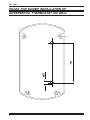
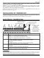
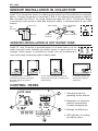
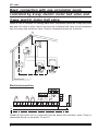
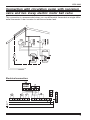
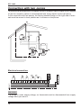
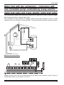
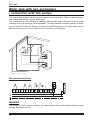
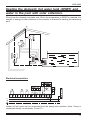
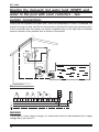
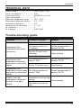
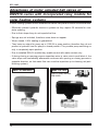
Differential thermostat for solar systems and combined heating sources DTC 100/3 Users manual Installation and maintenance instructions FIRT-ROTOTEHNIKA, s.p. Radegunda 54, SI-3330 MOZIRJE SLOVENIJA tel. +386 3 898 35 00 fax. +386 3 898 35 35 e-mail:[email protected] PM7-0141-01DTC100-3ang DTC 100/3 HOLES FOR EASIER INSTALLATION OF DIFFERENTIAL THERMOSTAT ON WALL 2 DTC 100/3 DEAR CUSTUMER Congratulations you have bought a DTC 100/3 differential thermostat, manufactured according to the latest quality and safety standards. It is made according to the state of art and efficiently utilises solar energy or alternative sources for domestic water heating. We are convinced that the use of our product will satisfy your needs too and help you to save your money. Thanks for your confidence FIRT Rototehnika THE SET CONSIST OF: - Diferential thermostat DTC 100/3 - T1 collector sensor with silicone conductor - T2 and T3 hot water tank sensor with PVC conductor - Clip for sensor fastening with fixing springs - Instruction for use - Warranty certificate In case any of above specified elements are missing or are defective require your dealer to replace it. Read the instructions carefuly in order to be able to make use of all advantages of the product. ! WARNING ! All examples listed in the instructions are merely indicativ. The manufacturer accepts no responsebility for incorrect hydraulic connection of machine part of installations should comply with all safety regulations defined by law and the rules. We reserve the right to modify the instructions and the technical data of the product without prior notice 3 DTC 100/3 GENERAL DTC 100/3 is a double differential thermostat, designed for domestic water heating with two storage tanks from one heating source (solar collectors, boilers, heating pumps,...). It is used in the systems where during the day one storage tank cannot accumulate whole energy, which is disposal from solar collectors. The thermostat controls circulation pump and motorised diverter valve (ROTODIVERT) or 3-way motorised ball valve (EMV 710, 830, 930). With special el. connection it can control two pumps or 2-way motorised ball valve. The thermostat enables setting of two parameters, i.e.: 1. Regulation of maximum temperature in hot water storage tank from 10° to 90°C. This temperature is defined by T2 and T4 sensor witch is generally mounted in upper third of heat exchanger in water storage tank. 2. Regulation of difference for higher exchanger from 2° to 15°C With this parameter you define how much the value of the source temperature (collector, boiler,...) should exceed the temperature of water around the exchanger in storage tank, that the regulator activates the pump. The difference is set in relation to the volume of heat losses of the system which depend on lenghts of pipelines from source to hot water tank and on pipeline insulation. OPERATION Double differential thermostat DTC 100/3 measures the temperature in the heating source (solar collector, heating boiler ...) and the temperature in two storage tanks (boiler, swimming pool ...). One of the storage tanks has precedence over other - in practice means usually the smaller boiler - in the smaller boiler is need for domestic hot water. When the boilers temperature is reached, then thermostat changeover the 3-way ball valve or diverter valve for heating second larger storage tank. If the temperature from heating source (solar collector) is not high enough according the set temperature for primary storage tank but is higher then the temperature from second storage tank, then thermostat changeover the 3-way ball valve or diverter valve for heating second larger storage tank. When the both temperatures are reached to maximum temperature, the pump is switched off. Heating effect is provided, when heating source temperature is higher than the temperature of the user (water in hot water tank). Consequently minimum adjustable difference is 5° (factory set). When the difference is smaller then the set difference, thermostat switches off the pump. In the set are three sensors. One is installed in the heating source (solar collector) and another two in two storage tanks in upper part of exchanger. 4 DTC 100/3 Sensors T1 and T2 are used for primary heating circuit, which heats water in smaller storage tank (domestic hot water storage tank). Sensors T1 and T4 are used for secondary heating circuit, which heats water in larger boiler (or swimming pool, etc). Sensor T1 is heating source sensor (usually solar collector), sensors T2 and T4 are storage tank sensors. Differential thermostat DTC 100/3 can be used like a single differential thermostat, but without connection of sensor T4. INSTALATION OF THERMOSTAT Install the thermostat on hot water tank chasing or close to it. Do not install it under the pipe fittings or valves due to possible water dripping on its housing. ELECTRICAL CONNECTION terminals for use with two pumps connection bridge (factory default) bridge for use with two pumps connection Grounding wires should be connected to special screw terminals situated on right side of terminal strips. TERMINAL CONNECTION 1,2 Sensor T4 - secondary water storage tank, grey 5,6 Sensor T2 - primary domestic hot water tank, grey 7,8 Sensor T1 - heating source (solar collector, ...), red silicon 9 L - phase: changeover 3-way electric motor ball valve to position for heating secondary storage tank 10 N - neutral L - phase: changeover 3-way electric motor ball valve to position 11 for heating primary domestic hot water storage tank 12 L - phase: circulation pump or phase for opening 2-way electric motor ball valve 13 N - neutral 14 L - phase: for closing 2-way electric motor ball valve 15 L - phase: connection for mains: 230VAC, 50Hz 16 N- neutral: connection for mains: 230VAC, 50Hz ! WARNING ! The thermostat is designed for fixed instalation. When performing electric instalation, an element should be inserted which enables at least 3 mm separation of thermostat from the mains (switch or socket). Prir to each intervention in the thermostat, first disconnect it from the mains. 5 DTC 100/3 SENSOR INSTALLATION IN COLLECTOR: Install T1 as immersion sensor in collecting pipe at the top of the collectors in provided sleeve. Connect the sensor on terminals 7 and 8. For extension the sensors cable to 50m use cable 2x0.75mm2, for longer cables use cable 2x1,5mm2. On the spot, where is connection with sensors cable and extension cable, is recommended to use VDR resistor. T piece 1/2 flow direction VDR resistor Pipe 1/2 thermo-shrinkable tubes sensor conductor extension conductor SENSORS INSTALLATION IN HOT WATER TANK: Install T2 and T4 sensor to provided place in hot water tank or on hot water tank wall under isolation as contact sensor in upper part of exchanger. When sensor is mounted as contact one we recommend to coat it with heat conducting paste or liquid metal. T2 T4 T2 T4 In special purpose vertical or horizontal tube (sensor should be protected against accidental extraction). T2 T4 T2 T4 On hot water tank with clip, wire and spring strip (use paste for better heat transmission). In special purpose side tube (protect against extraction). CONTROL PANEL 1 Operation switch for operating mode selector 2 Regulation of maximum required temperature in water storage tanks 3 Settings the difference 4 LED indicator of working circulation pump 6 DTC 100/3 USE OF SELECTOR SWITCH FOR MANUAL CONTROL With selector switch (2) you select one of the following models of operation: ON 1 Continuously heating of primary water tank, secondary is out of function. There is no limit of water tank temperature ON 2 Continuously heating of secondary water tank, primary is out of function. There is no limit of water tank temperature. OFF Irrespective of temperature values, the pump is off. AUTO Automatic operation of thermostat (normal operation) ! WARNING ! OFF does not enable galvanic separation from mains. When replacing the pump, disconnect supply voltage! Temperature setting of storage tank You can set maximum water temperature of both storage tanks (from 10° to 90°). When the temperature is reached in the primary storage tank, the thermostat changeover 3way electric motor ball valve to heating the secondary storage tank. When the temperature is reached in the secondary storage tank, deactivate the pump regardless the temperature of heating source. If the appliance with limited maximum temperature of inflow uses hot water, this setting is very useful. WARNING In the systems with heating pump is recommended to consult with manufacturer. Its forbidden to directly control the compressor of heating pump with the thermostat! It is recommended that you built in system protection for over heating the storage tank (in case of error). Differential thermostat DTC 100/3 can be used like a single differential thermostat(one storage tank), but without connection of sensor T4. If you later built in second storage tank, than you built in 3-way motor ball valve and connect the sensor T4. Difference setting: The difference is set with the knob depending of heat losses of the system, which depend on lengths of pipelines from source to storage tank and on pipeline insulation. It can be set from 5° to 10°C. If the pipes of installation are good insulate and they are not longer than 15m, the difference should be 5°. With the pipes length or weaker insulation the difference must be higher. 7 DTC 100/3 Basic connection with one circulation pump controlled by 2-way electric motor ball valve and 3-way electric motor ball valve. When is fulfil a condition for heating water tank, thermostat opens the 2-way ball valve and when the valve is open it switch on the pump. Instead of ball valve can be connected only the pump and nonreturn valve. Pump is connected directly on terminals. Electrical connection: Instead of ball valve can be connected only the pump and nonreturn valve. Pump is connected directly on terminals 12 and 13. 8 DTC 100/3 Connection with circulation pump with nonreturn valve and two 2-way electric motor ball valve This connection is recommended when you use differential thermostat as single differential thermostat. Later is easier to add second water tank. Electrical connection: 9 DTC 100/3 Connection with two pumps To prevent the termosyphonic circulation is built in nonreturn valve in each circuit. Instead of use the nonreturn valves is recommended use 2-way electric motor ball valves. In the connection with two pumps, the factory-installed bridge on the right side of terminals must be moved in lover position as it is shown on the picture. Electrical connection: WARNING The bridge is under supply voltage, so thermostat must be disconnected from supply voltage when you move it. 10 DTC 100/3 Water tank with two exchangers - connection with one circulation pump controlled by 2-way electric motor ball valve and 3-way electric motor ball valve The connection enables fast warming of upper part of water tank. When is warm enough, than thermostat heats a whole water tank. This connection is very efficient in heating systems with solar collectors. Even by weak intensity of sun (at mornings, cloudy weather...) enough heats the smaller quantity of water. Electrical connection: Instead of ball valve can be connected only the pump and nonreturn valve. Pump is connected directly on terminals 12 and 13. 11 DTC 100/3 Water tank with two exchangers - connection with two pumps The connection enables fast warming of upper part of water tank. When is warm enough, than thermostat heats a whole water tank. This connection is very efficient in heating systems with solar collectors. Even by weak intensity of sun (at mornings, cloudy weather...) enough heats the smaller quantity of water. In the connection with two pumps, the factory-installed bridge on the right side of terminals must be moved in lover position as it is shown on the picture Electrical connection: WARNING The bridge is under supply voltage, so thermostat must be disconnected from supply voltage when you move it. 12 DTC 100/3 Heating the domestic hot water tank (DHWT) and water in the pool with solar collectors. Priority has the domestic hot water tank. When the temperature in DHWT is reached, the surplus of energy of solar collectors in the summer is directed for heating the swimming pool. Electrical connection: Instead of ball valve can be connected only the pump and nonreturn valve. Pump is connected directly on terminals 12 and 13. 13 DTC 100/3 Heating the domestic hot water tank (DHWT) and water in the pool with solar collectors - two pumps connection. Priority has the domestic hot water tank. When the temperature in DHWT is reached, the surplus of energy of solar collectors in the summer is directed for heating the swimming pool. In the connection with two pumps, the factory-installed bridge on the right side of terminals must be moved in lover position as it is shown on the picture. Electrical connection: WARNING The bridge is under supply voltage, so thermostat must be disconnected from supply voltage when you move it. 14 DTC 100/3 TECHNICAL DATA Supply voltage .................................. 230V, 50Hz +/-10% Power consumption ......................... 4 VA Pump relay rating ............................. 3A/230VAC cos ρ 0.6 Type of thermostat ............................ P Adjustable temperature range ......... 10°C - 90°C Temperature difference setting ........ 5°C - 15°C Hysteresis of difference .................... 2°K Hysteresis of the thermostat ............. 1° - 2°K Nr. of sensors .................................... 3 Nr. of outputs ..................................... 2 (230 VAC) Trouble-shooting guide TROUBLE Irrespective of the temperatures all circuits are inactive POSSIBLE FAULIRE REMEDY Plug not connected Check main power The selector switch is in "0" position Set the selector switch in position "AUTO" Sensors T2 and T4 are interupted Check sensors Sensor T1 is short circuit Irrespective of the temperature the primary water tank is continuously heated The selector switch is in position "ON1" Set the selector switch in position "AUTO" Sensor T2 is short circuit Check sensor Irrespective of the temperature the secondary The selector switch is in Set the selector switch in water tank is continuously position "ON2" position "AUTO" heated The water tank In spite of enough temperature is not set high temperature in collectors, enough Check settings the water is not warm The difference is set too enough high 15 DTC 100/3 Advantages of motor actuated ball valves of EMV110..series with incorporated relay module for solar heating systems In solar heating systems motor actuated ball valves can prevent various inconveniences. - Effectively prevent hydraulic shocks in systems as they require 30 seconds for complete opening. - Due to their shape they do not impede the flow. - Springs are not included, therefore noise does not appear. - When closed, 100% sealing is guaranteed. - They have an output for pump up to 1000 W in open position, therefore they do not present a hydraulic load for pump in closed position. They enable pump switching on only in completely open position. - Due to installed RELAY module they enable control with make contact only. - If during closing or opening process impurities enter in valve, which could block it, the valve stops and immediately afterwards continues with opening or closing process in opposite direction, so that water flow can rinse the impurities up to cleaning net (antiblocking system). EMV 110..602/4230 EMV 110..800 Built in relay module RM 24/48 16