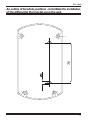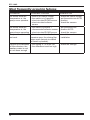
1
DTC 100/2 Differential thermostat for solar system and combined multi-source heating DTC 100/2 User manual Instructions for installation and maintenance FIRŠT-ROTOTEHNIKA, s.p. Radegunda 54, 3330 MOZIRJE PE VELENJE Koroška cesta 56a, 3320 VELENJE tel. 03/ 898 35 00, fax. 03/ 898 35 35 e-mail: [email protected] CENTRALNI SERVIS Koroška cesta 56a, 3320 VELENJE tel.03 / 898 35 30 031 / 608 393, 041 / 608 393 e-mail: [email protected] http://www.first.si ID-4870-04-DTC100-2-ang.indd 1 DTC 100/2 Dear customer We congratulate you on your choice. By purchasing the differential thermostat DTC... you have selected a product, that complies with all the most recent quality and safety standards. It includes state-of-the-art knowledge of how to harness solar energy and other alternative sources for water heating purposes in homes and offices. We are convinced that you will find using our product highly costefficient. Thanks for your trust, FIRŠT Rototehnika The kit includes: 1. Differential thermostat DTC 100/2 2. Sensor T1 with a silicon conductor for the collectors 3. Sensor T2 with a PVC conductor for the DHWS 4. A clamp with two fastening springs - to fasten the sensor 5. Instructions for use 6. Warranty card In case any of these are missing or damaged, demand your seller to supply you with a replacement ! Read these instructions carefully, as this will allow you to benefit from all the possibilities offered by this product. NOTICE The examples of how to use the DTC/2 listed in this booklet are only schematic. We accept no responsibility for incorrect hydraulic coupling of the mechanical part of the installations. The mechanical installations must, as well as the electrical ones, comply with all the safety regulations prescribed by the law and the regulation books. We reserve the right to modify the instructions and the technical data of the product without prior notice. 2 DTC 100/2 GENERAL INFORMATION DTC 2 is a single differential thermostat designed for heating water in homes and offices from one source. (solar collectors, hot water boilers, heat pumps, etc.) The thermostat controls one pump or electrically actuated motor ball valve. The thermostat allows setting two parameters, that is: 1. Setting the maximum temperature in the DHWS (Domestic Hot Water Storage) between 10°C and 90°C. This temperature is determined by sensor T2, which is usually installed in the upper third of the exchanger. 2. Setting the difference between the temperature in the boiler and the source of heating (collectors). It can be set between 5 and 15 K. By means of this setting we define, by how many degrees the temperature of the source of heating needs to exceed the temperature of the water around the exchanger in the DHWS in order to start the operation of the valve and put the pump into operation. The setting of the difference depends on the amount of temperature losses on the system. These losses mainly depend on the length and the quality of the insulation of the tubes leading from the source to the DHWS. OPERATION Single differential thermostat DTC 100/2 measures the temperature in the source (collectors, the stove) and in the consumer (DHWS). In order to achieve heating effects, the temperature of the heating body (the heater in the boiler) needs to exceed the temperature of the water in the consumer (the boiler) by at least 3 to 5 K. This is why the minimum adjustable difference is 5 K (factory setting). When the temperature in the source exceeds the temperature of the water around the exchanger in the consumer, the thermostat opens the valve (EMV), or actuates the pump and closes the valve, or switches off the pump when the difference in temperature is lower than 3 to 4 K. The thermostat de-activates the pump also in the case when the achieved temperature of the water in the boiler equals the pre-set temperature (adjustable between 10 and 90°C). The kit includes two sensors (T1 and T2), of which one is installed into the heating source and the other into the upper half of the exchangers in individual boilers. ADVANTAGES * The adjustable temperature difference between the source and the consumer is within 5 and 15 K. * Potential output with a reversing contact SPDT ( ) 230V, 50Hz. * The setting of the required temperature in the consumer (DHWS) is between 10 and 90°C. * The system is supported either by a circulation pump or by an electrically actuated motor ball valve. * Manual control is provided to allow for operation checks if required, or to be used in the case of a sensor breakdown. * The thermostat can be completely turned off. 3 DTC 100/2 INSTALLATION OF THE THERMOSTAT The thermostat is fastened upon the coat of the DHWS (Domestic Hot Water Storage) or to its immediate neighbourhood. By simply using the outline of the boreholes drawn on page 11 of this booklet, the thermostat can easily be fastened to the wall in the heating room. Do not fasten the thermostat below tube joints or valves to avoid water dropping on its housing. Installation of the sensor into the collector Sensor T1 is inserted as an immersion sensor into the immersion tube provided on the upper side of the collectors (figure A). The sensor is connected to clips 1 and 2. To lengthen the cable up to 50m you can use the 2x0.75 mm2 standard cable. It is recommendable, to allocate a VDR resistor (Figure B) to the point where the cable of the sensor and the lengthening cable join to prevent sudden jumps of voltage (due to lightening strokes, for example). For greater lengths or in the areas where lightening strikes are more likely to happen, it is advisable to use an armoured cable, where the armoured coating is connected to the grounding terminals. direction of the current T item 1/2” immersion tube 1/2” figure: A VDR resistor lengthening cable thermo-shrinkable tubes cable of the sensor figure: B Installation of the sensor into the boiler Sensor T2 must be fixed to the provided location in the DHWS (Domestic Hot Water Storage) or to the DHWS wall below the insulation as a surfacemounted sensor in the upper half of the exchanger. If the sensor is installed in the surface-mounted way, it is advisable to lubricate it beforehand with a heat conducting grease or liquid metal. Installation of T2 into a specially provided vertical or horizontal tube (protect the sensor against unwanted extraction) 4 Installation of T2 upon the boiler by means of a clamp and a spring ribbon. (use glease for better conductivity of heat. Installation into a specially designed lateral tube (protect from unwanted extraction) DTC 100/2 Electrical CONNECTION The grounding cables are to be connected to the specially designed terminals, to the right of the coupling terminals. TERMINAL 1,2 3,4 12 13 14 15 16 CONNECTION sensor T1 - sensor of the source (collector) KF, silicon, 2x0.25 mm2 , 2 m long, with two spring ribbons and one angle clamp, orange sensor T2 - DHWS sensor, 2x0.34mm2 1.5 m long, gray phase (L) for closing the electrically actuated motor valve (EMV 110) neutral connector (N) phase (L) of the pump, i.e. opening of the electrically actuated motor valve (EMV 110.., find in our production line) L - phase, mains connection 230 V, 50 Hz. N - neutral, mains connection 230 V, 50 Hz. NOTICE The thermostat is designed to be fastened permanently. While putting in the electrical installation, it is necessary to insert an safety element to allow the thermostat at least a 3mm - distance from the mains (a switch or a power cord). For any repairs inside the thermostat, it must be fully disconnected from the mains. TECHNICAL DATA Supply voltage.............................................230V 50Hz +/- 10% Power consumption.....................................4 VA Pump relay rating........................................3A/230VAC cos 0,6 Type of thermostat.......................................P Max. temp. of water.....................................100°C Interval of operation.....................................10 - 90°C Setting the difference...................................5 - 15K Hysteresis of the thermostat........................1 - 2K Nr. of sensors..............................................2 Nr. of outputs...............................................1 (230 VAC reversing SPDT ) 5 DTC 100/2 DESCRIPTION OF THE FRONT PANEL ELEMENTS LEGEND : 1 - The switch for manual control (selection of a mode of operation) 2 - Button for adjustment of the temperature of the water in the DHWS (operates only when the gliding switch (1) is in position AUTO.) 3 - Potentiometer for the adjustment of the switching off temperature difference be tween the DHWS and the source of heating. (recommended setting is between 5 and 10K) 4 - LED to signal operation USE OF THE MANUAL CONTROL SWITCH 0 No matter what the value of the temperature is, the pump is off, the valve remains closed. AUTO Thermostat operates automatically (normal operation) 1 6 No matter what the value of the temperature is, the valve remains open, the pump keeps operating. DTC 100/2 Setting the temperature in the DHWS By turning the right button (2) on the cover of the thermostat, you can set the maximum temperature of the water in the DHWS (Domestic Hot Water Storage) between 10 and 90°C. When the set temperature is achieved, the thermostat closes the valve and turns off the pump. This allows connection of appliances using hot water while operating, such as the washing machine and the dish-washing) While using this option, attention needs to be paid to the allowed input temperature of the water, as prescribed by the manufacturer for each individual appliance. WARNING: If heating the water in a system including a heat pump, it is necessary to consult the heat pump manufacturer concerning the appropriate coupling. It is forbidden to switch on the thermostat, where this, provided that the temperature of the water is risen, turns the compressor off. With the appliances using hot water, additional protection against overheating is required, which is to close the supply of water in case of thermostat failure. Setting the temperature difference (the switching difference) The temperature difference between the source of heating and the consumer (the DHWS) is set to the value required by the mechanical part of the installation by means of a screwdrive and the potentiometer (3) on the cover of the thermostat. When using collector heating this difference is between 5 and 10 K, depending on the length of the tubes and the quality of their insulation. If the tubes connecting the collectors with the boiler are insulated and their total length does not exceed 15 meters, the difference can be 5 K, whereas it needs to be increased in proportion to their length and poorer insulation. 7 DTC 100/2 Basic coupling with a pump controlled by an electric motor actuated ball valve ( EMV 110 series 800) When the conditions required for the boiler to star heating are met, the EMV 110 series 800 opens. The pump however, is put into operation only when the valve is open. DTC Differential thermostat DTC 100/2 T1, T2 Sensors T1 - sensor located in the collector T2 - sensor located in the DHWS P P - circulation pump EMV Electric motor actuated ball valve: EMV 110.. series 800 EMV 110.. series 801 MV 110..compact Electrical connection 8 DTC 100/2 Example of coupling with a pump. In this case it is necessary to connect behind the pump a non-return valve to avoid unwanted circulation of water. DTC Differential thermostat DTC 100/2 T1, T2 Sensors T1 - sensor located in the collector T2 - sensor located in the DHWS P P - circulation pump Non-return valve Electrical connection 9 DTC 100/2 Basic coupling with a pump controlled by the electrically actuated motor ball valve EMV 110 series 800. It is used in cases which require temperature regulation of sanitary water in the classical oil or solid fuel powered boiler. When the conditions which require heating of the DHWS (Domestic Hot Water Storage) have been met, the valve EMV 110 series 800 opens , but the pump is put into operation only when the valve is open. DTC Differential thermostat DTC 100/2 T1,T2 Sensors T1 - sensor located in the collector T2 - sensor located in the DHWS P P - circulation pump EMV Electric motor actuated ball valve: EMV 110.. series 800 EMV 110.. series 801 MV 110..compact Electrical connection 10 DTC 100/2 An outline of borehole positions - to facilitate the installation of the differential thermostat upon the wall. 11 DTC 100/2 Most frequently occuring failures PROBLEM POSSIBLE FAILURE ELIMINATION No matter what the temperature is, the pump never operates - there is no mains voltage - the switch is in 0-position - short-circuited DHWS sensor - short-circuited collector sensor - check the mains voltage - put the switch into AUTO position - check the sensors No matter what the temperature is, the pump keeps operating - the switch in position 1 - disconnected collector sensor - short-circuited DHWS sensor - put the switch into position AUTO - check the sensors Temperature limits do not work - the motor actuated ball valve remains open, the closing flap stays open (termal circulation of water is possible) - check the machine installation Despite the warmness of the collectors, the sanitary water is cool or not warm enough - the setting of T2 is too low - the difference is set too high - check the settings 12