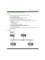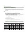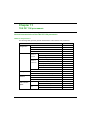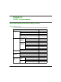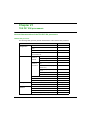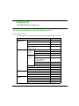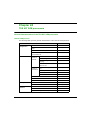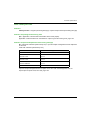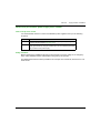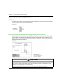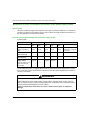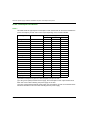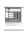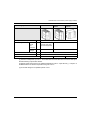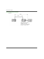
1
Premium and Atrium using Unity Pro 35010524 10/2013 Premium and Atrium using Unity Pro Processors, racks and power supply modules Implementation manual 35010524.09 10/2013 www.schneider-electric.com The information provided in this documentation contains general descriptions and/or technical characteristics of the performance of the products contained herein. This documentation is not intended as a substitute for and is not to be used for determining suitability or reliability of these products for specific user applications. It is the duty of any such user or integrator to perform the appropriate and complete risk analysis, evaluation and testing of the products with respect to the relevant specific application or use thereof. Neither Schneider Electric nor any of its affiliates or subsidiaries shall be responsible or liable for misuse of the information contained herein. If you have any suggestions for improvements or amendments or have found errors in this publication, please notify us. No part of this document may be reproduced in any form or by any means, electronic or mechanical, including photocopying, without express written permission of Schneider Electric. All pertinent state, regional, and local safety regulations must be observed when installing and using this product. For reasons of safety and to help ensure compliance with documented system data, only the manufacturer should perform repairs to components. When devices are used for applications with technical safety requirements, the relevant instructions must be followed. Failure to use Schneider Electric software or approved software with our hardware products may result in injury, harm, or improper operating results. Failure to observe this information can result in injury or equipment damage. © 2013 Schneider Electric. All rights reserved. 2 35010524 10/2013 Table of Contents Safety Information . . . . . . . . . . . . . . . . . . . . . . . . . . . . . About the Book. . . . . . . . . . . . . . . . . . . . . . . . . . . . . . . . Part I Premium and Atrium PLC stations . . . . . . . . . . . . Chapter 1 Introduction to Premium and Atrium PLC stations. . . Premium PLC station. . . . . . . . . . . . . . . . . . . . . . . . . . . . . . . . . . . . . . Atrium PLC station. . . . . . . . . . . . . . . . . . . . . . . . . . . . . . . . . . . . . . . . Chapter 2 General introduction to the components of a PLC station . . . . . . . . . . . . . . . . . . . . . . . . . . . . . . . . . . . . . . . General Introduction to Premium Processors . . . . . . . . . . . . . . . . . . . General Introduction to Atrium Processors . . . . . . . . . . . . . . . . . . . . . General introduction to racks. . . . . . . . . . . . . . . . . . . . . . . . . . . . . . . . General introduction to TSX PSY power supply modules . . . . . . . . . . General introduction to Process and AS-i power supply modules. . . . General introduction to the rack extender module. . . . . . . . . . . . . . . . General Introduction to Input/Output Modules. . . . . . . . . . . . . . . . . . . General introduction to TSX CTY/CCY counting modules . . . . . . . . . Introduction to Axis Control Modules . . . . . . . . . . . . . . . . . . . . . . . . . . General introduction to step by step command modules . . . . . . . . . . General introduction to communication . . . . . . . . . . . . . . . . . . . . . . . . General introduction to the AS-i bus interface module: TSX SAY 100 General introduction to the TSX ISPY weighing module . . . . . . . . . . . General introduction to the emergency stop monitoring module . . . . . General introduction to the TSX FAN ventilation module . . . . . . . . . . Chapter 3 General introduction to the different configurations of a PLC station. . . . . . . . . . . . . . . . . . . . . . . . . . . . . . . . . . Different Types of Premium PLC Stations . . . . . . . . . . . . . . . . . . . . . . Different Types of PLC Station with Atrium Processors . . . . . . . . . . . Chapter 4 General introduction to PLC networks. . . . . . . . . . . . . General introduction to the Modbus bus . . . . . . . . . . . . . . . . . . . . . . . General introduction to a Modbus Plus network . . . . . . . . . . . . . . . . . General introduction to a Fipway network . . . . . . . . . . . . . . . . . . . . . . General introduction to an Ethernet network . . . . . . . . . . . . . . . . . . . . General introduction to communication by modem . . . . . . . . . . . . . . . General introduction to the Uni-Telway Bus . . . . . . . . . . . . . . . . . . . . General introduction to Fipio field bus . . . . . . . . . . . . . . . . . . . . . . . . . 35010524 10/2013 11 13 15 17 18 20 21 22 24 26 27 28 30 31 33 34 35 36 40 41 42 43 45 46 49 53 54 55 56 57 58 59 60 3 General Introduction to CANopen Field Bus . . . . . . . . . . . . . . . . . . . . Introduction to AS-i Bus . . . . . . . . . . . . . . . . . . . . . . . . . . . . . . . . . . . . General introduction to Profibus DP field bus . . . . . . . . . . . . . . . . . . . General introduction INTERBUS field bus . . . . . . . . . . . . . . . . . . . . . . Presentation of the Jnet network . . . . . . . . . . . . . . . . . . . . . . . . . . . . . Chapter 5 Operating Standards and Conditions . . . . . . . . . . . . . Standards and Certification . . . . . . . . . . . . . . . . . . . . . . . . . . . . . . . . . Operating conditions and environmental conditions to be avoided . . . Premium PLC protection processing . . . . . . . . . . . . . . . . . . . . . . . . . . Part II TSX P57/TSX H57 Premium processors . . . . . . . Chapter 6 TSX P57/TSX H57 processors: introduction. . . . . . . . General Introduction. . . . . . . . . . . . . . . . . . . . . . . . . . . . . . . . . . . . . . . Physical Description of TSX P57/TSX H57 Processors. . . . . . . . . . . . Real-time clock. . . . . . . . . . . . . . . . . . . . . . . . . . . . . . . . . . . . . . . . . . . Catalog of TSX 57 Processors. . . . . . . . . . . . . . . . . . . . . . . . . . . . . . . Size of Data on Premium and Atrium PLCs . . . . . . . . . . . . . . . . . . . . . Chapter 7 TSX P57/TSX H57 processors: installation . . . . . . . . . Positioning the processor module . . . . . . . . . . . . . . . . . . . . . . . . . . . . How to mount processor modules . . . . . . . . . . . . . . . . . . . . . . . . . . . . Installation of Modules next to TSX P57 0244/104/154 Processors . . Standard Memory Cards for PLCs . . . . . . . . . . . . . . . . . . . . . . . . . . . . Application\File and File Storage Type Memory Cards . . . . . . . . . . . . Processing on insertion/extraction of a PCMCIA memory extension card on a Premium PLC. . . . . . . . . . . . . . . . . . . . . . . . . . . . . . . . . . . . Mounting/Removing PCMCIA Memory Extension Cards on a TSX P57/TSX H57 Processor . . . . . . . . . . . . . . . . . . . . . . . . . . . . . . . . . . . Chapter 8 TSX P57/TSX H57 processors: diagnostics. . . . . . . . . Display . . . . . . . . . . . . . . . . . . . . . . . . . . . . . . . . . . . . . . . . . . . . . . . . . Precautions to be taken when replacing a TSX P57/TSX H57 processor . . . . . . . . . . . . . . . . . . . . . . . . . . . . . . . . . . . . . . . . . . . . . . . Changing the TSX P57/TSX H57 RAM Memory Backup Battery . . . . Changing the Batteries of a PCMCIA Memory Card . . . . . . . . . . . . . . Battery Lifetimes for the PCMCIA Memory Card . . . . . . . . . . . . . . . . . What happens after you press the processor RESET button . . . . . . . Finding errors using processor state LEDs . . . . . . . . . . . . . . . . . . . . . Non blocking errors . . . . . . . . . . . . . . . . . . . . . . . . . . . . . . . . . . . . . . . Blocking errors . . . . . . . . . . . . . . . . . . . . . . . . . . . . . . . . . . . . . . . . . . . Processor or system errors . . . . . . . . . . . . . . . . . . . . . . . . . . . . . . . . . 4 61 63 64 65 67 69 70 71 77 79 81 82 84 87 89 93 95 96 98 100 101 104 108 110 115 116 118 119 122 126 135 136 137 139 140 35010524 10/2013 Chapter 9 TSX P57 0244 processors . . . . . . . . . . . . . . . . . . . . . . . General Characteristics of the TSX P57 0244 processors . . . . . . . . . Chapter 10 TSX P57 104 processors . . . . . . . . . . . . . . . . . . . . . . . . General characteristics of the TSX P57 104 processors. . . . . . . . . . . Chapter 11 TSX P57 154 processors . . . . . . . . . . . . . . . . . . . . . . . . General characteristics of the TSX P57 154 processors. . . . . . . . . . . Chapter 12 TSX P57 1634 processors . . . . . . . . . . . . . . . . . . . . . . . General Characteristics of the TSX P57 1634 processors . . . . . . . . . Chapter 13 TSX P57 204 processors . . . . . . . . . . . . . . . . . . . . . . . . General characteristics of the TSX P57 204 processors. . . . . . . . . . . Chapter 14 TSX P57 254 processors . . . . . . . . . . . . . . . . . . . . . . . . General characteristics of the TSX P57 254 processors. . . . . . . . . . . Chapter 15 TSX P57 2634 processors . . . . . . . . . . . . . . . . . . . . . . . General Characteristics of the TSX P57 2634 processors . . . . . . . . . Chapter 16 TSX P57 304 processors . . . . . . . . . . . . . . . . . . . . . . . . General characteristics of the TSX P57 304 processors. . . . . . . . . . . Chapter 17 TSX P57 354 processors . . . . . . . . . . . . . . . . . . . . . . . . General Characteristics of the TSX P57 354 processors . . . . . . . . . . Chapter 18 TSX P57 3634 processors . . . . . . . . . . . . . . . . . . . . . . . General characteristics of the TSX P57 3634 processors . . . . . . . . . . Chapter 19 TSX P57 454 processors . . . . . . . . . . . . . . . . . . . . . . . . General characteristics of the TSX P57 454 processors. . . . . . . . . . . Chapter 20 TSX P57 4634 processors . . . . . . . . . . . . . . . . . . . . . . . General Characteristics of the TSX P57 4634 processors . . . . . . . . . Chapter 21 TSX P57 554 processors . . . . . . . . . . . . . . . . . . . . . . . . General Characteristics of the TSX P57 554 processors . . . . . . . . . . Chapter 22 TSX P57 5634 processors . . . . . . . . . . . . . . . . . . . . . . . General Characteristics of the TSX P57 5634 processors . . . . . . . . . Chapter 23 TSX P57 6634 processors . . . . . . . . . . . . . . . . . . . . . . . General Characteristics of the TSX P57 6634 processors . . . . . . . . . Chapter 24 TSX H57 24M processors. . . . . . . . . . . . . . . . . . . . . . . . General Characteristics of the TSX H57 24M processors . . . . . . . . . . Chapter 25 TSX H57 44M processors. . . . . . . . . . . . . . . . . . . . . . . . General Characteristics of the TSX H57 44M processors . . . . . . . . . . 35010524 10/2013 141 141 143 143 145 145 147 147 149 149 151 151 153 153 155 155 157 157 159 159 161 161 163 163 165 165 167 167 169 169 171 171 173 173 5 Chapter 26 Premium TSX P57/TSX H57 processor: general characteristics . . . . . . . . . . . . . . . . . . . . . . . . . . . . . . . . Features of UNITY Premium Processors. . . . . . . . . . . . . . . . . . . . . . . Electrical Characteristics of the TSX P57/TSX H57 Processors and Devices Which Can Be Connected or Integrated. . . . . . . . . . . . . . . . . Defining and counting application-specific channels . . . . . . . . . . . . . . Chapter 27 Processor performance . . . . . . . . . . . . . . . . . . . . . . . . . MAST task cycle time: introduction . . . . . . . . . . . . . . . . . . . . . . . . . . . MAST Task Cycle Time: Program Processing Ppt . . . . . . . . . . . . . . . MAST Task Cycle Time: Input/Output Internal Processing . . . . . . . . . Example of the calculation of cycle times of a MAST task under the following conditions . . . . . . . . . . . . . . . . . . . . . . . . . . . . . . . . . . . . . . . FAST Task Cycle Time . . . . . . . . . . . . . . . . . . . . . . . . . . . . . . . . . . . . Event Response Time . . . . . . . . . . . . . . . . . . . . . . . . . . . . . . . . . . . . . Part III Atrium processors . . . . . . . . . . . . . . . . . . . . . . . . . Chapter 28 Atrium processors: introduction . . . . . . . . . . . . . . . . . General introduction. . . . . . . . . . . . . . . . . . . . . . . . . . . . . . . . . . . . . . . Physical Description of Atrium Processors . . . . . . . . . . . . . . . . . . . . . Real-time clock. . . . . . . . . . . . . . . . . . . . . . . . . . . . . . . . . . . . . . . . . . . Dimensions of Atrium processor cards . . . . . . . . . . . . . . . . . . . . . . . . The different standard elements constituting an Atrium card. . . . . . . . The different optional elements constituting an Atrium card . . . . . . . . Catalog of Atrium Processors . . . . . . . . . . . . . . . . . . . . . . . . . . . . . . . Chapter 29 Atrium processors: installation . . . . . . . . . . . . . . . . . . Precautions to be taken during installation . . . . . . . . . . . . . . . . . . . . . Physical installation of the Atrium processor in the PC . . . . . . . . . . . . Logical installation of the Atrium processor on the X-Bus . . . . . . . . . . Operations to be carried out before installation . . . . . . . . . . . . . . . . . . How to configure the Atrium processor’s address on the X-Bus . . . . . How to configure the processor’s standard I/O address on the PCI bus How to install the Atrium processor card in the PC . . . . . . . . . . . . . . . Installing the 24 V power supply card . . . . . . . . . . . . . . . . . . . . . . . . . Integration of the Atrium processor within an X-Bus cable segment . . How to install/remove the memory extension card on the Atrium processor . . . . . . . . . . . . . . . . . . . . . . . . . . . . . . . . . . . . . . . . . . . . . . . 6 175 176 177 180 181 182 183 184 187 189 190 191 193 194 195 197 198 200 201 204 205 206 207 208 211 212 213 214 216 219 222 35010524 10/2013 Memory cards for Atrium processors. . . . . . . . . . . . . . . . . . . . . . . . . . How to install/remove communication cards on the Atrium processor Processing on insertion/extraction of a PCMCIA memory card on an Atrium PLC . . . . . . . . . . . . . . . . . . . . . . . . . . . . . . . . . . . . . . . . . . . . . Precautions to be taken when replacing an Atrium processor . . . . . . Chapter 30 Atrium processors: Diagnostics . . . . . . . . . . . . . . . . . . Description of Atrium Processor LEDs . . . . . . . . . . . . . . . . . . . . . . . . Changing the Atrium RAM memory backup battery . . . . . . . . . . . . . . What happens after you press the processor RESET button . . . . . . . How the Atrium processor behaves after an action on the PC . . . . . . Finding errors via the processor status LEDs . . . . . . . . . . . . . . . . . . . Chapter 31 TSX PCI 57 204 processor . . . . . . . . . . . . . . . . . . . . . . . General characteristics of the TSX PCI 57 204 processors . . . . . . . . Chapter 32 TSX PCI 57 354 Processor . . . . . . . . . . . . . . . . . . . . . . . General Characteristics of the TSX PCI 57 354 Processor . . . . . . . . . Chapter 33 Atrium processors: general characteristics . . . . . . . . Features of UNITY Atrium Processors . . . . . . . . . . . . . . . . . . . . . . . . Electrical Characteristics of the Atrium Processors and the Devices Which Can Be Connected and Integrated. . . . . . . . . . . . . . . . . . . . . . Defining and counting application-specific channels . . . . . . . . . . . . . . Processor performance . . . . . . . . . . . . . . . . . . . . . . . . . . . . . . . . . . . . Part IV TSX PSY supply modules . . . . . . . . . . . . . . . . . . . Chapter 34 TSX PSY… supply modules: introduction . . . . . . . . . . General introduction . . . . . . . . . . . . . . . . . . . . . . . . . . . . . . . . . . . . . . Supply modules: description . . . . . . . . . . . . . . . . . . . . . . . . . . . . . . . . Catalog of TSX PSY... supply modules . . . . . . . . . . . . . . . . . . . . . . . . Chapter 35 TSX PSY … supply modules: installation . . . . . . . . . . Installation/mounting TSX PSY supply modules . . . . . . . . . . . . . . . . . Rules for connecting TSX PSY supply modules . . . . . . . . . . . . . . . . . Connecting alternating current power supply modules . . . . . . . . . . . . Connecting direct current power supply modules from a floating 24 or 48 VDC direct current network . . . . . . . . . . . . . . . . . . . . . . . . . . . . . . Connecting DC power supply modules from an AC network. . . . . . . . Sensor and pre-actuator power supply servo control . . . . . . . . . . . . . Definition of protection devices at the start of a line . . . . . . . . . . . . . . 35010524 10/2013 224 225 228 229 231 232 234 237 238 239 241 241 243 243 245 246 247 250 251 253 255 256 258 260 263 264 265 267 269 271 275 278 7 Chapter 36 TSX PSY … supply modules: diagnostics . . . . . . . . . . Display on TSX PSY supply modules . . . . . . . . . . . . . . . . . . . . . . . . . Back-up battery on TSX PSY ... power supply modules . . . . . . . . . . . Power supply failure to rack other than rack 0 . . . . . . . . . . . . . . . . . . . What happens after pressing the RESET button on a power supply module . . . . . . . . . . . . . . . . . . . . . . . . . . . . . . . . . . . . . . . . . . . . . . . . . Alarm relay on TSX PSY supply modules . . . . . . . . . . . . . . . . . . . . . . Characteristics of the alarm relay contact . . . . . . . . . . . . . . . . . . . . . . 285 287 288 290 Chapter 38 TSX PSY power supply modules: breakdown of power consumption and power . . . . . . . . . . . . . . . . . . . . . . . . 293 Chapter 37 TSX PSY … supply modules : auxiliary functions . . . Breakdown of power consumption for selection of the power supply module . . . . . . . . . . . . . . . . . . . . . . . . . . . . . . . . . . . . . . . . . . . . . . . . . Power consumption breakdown . . . . . . . . . . . . . . . . . . . . . . . . . . . . . Power consumption breakdown . . . . . . . . . . . . . . . . . . . . . . . . . . . . . . Power consumption breakdown . . . . . . . . . . . . . . . . . . . . . . . . . . . . . . Power Consumption Breakdown . . . . . . . . . . . . . . . . . . . . . . . . . . . . . Power consumption breakdown . . . . . . . . . . . . . . . . . . . . . . . . . . . . . . Breakdown of power . . . . . . . . . . . . . . . . . . . . . . . . . . . . . . . . . . . . . . Chapter 39 TSX PSY 2600 power supply module . . . . . . . . . . . . . . Characteristics of the TSX PSY 2600 power supply module . . . . . . . . Chapter 40 TSX PSY 5500 power supply module . . . . . . . . . . . . . . Characteristics of the TSX PSY 5500 power supply module . . . . . . . . Chapter 41 TSX PSY 8500 power supply module . . . . . . . . . . . . . . Characteristics of the TSX PSY 8500 power supply module . . . . . . . . Chapter 42 TSX PSY 1610 power supply module . . . . . . . . . . . . . . Characteristics of the TSX PSY 1610 power supply module . . . . . . . . Chapter 43 TSX PSY 3610 power supply module . . . . . . . . . . . . . . Characteristics of the TSX PSY 3610 power supply module . . . . . . . . Chapter 44 TSX PSY 5520 power supply module . . . . . . . . . . . . . . Characteristics of the TSX PSY 5520 power supply module . . . . . . . . Part V Process power supplies . . . . . . . . . . . . . . . . . . . . Chapter 45 Process power supply modules: introduction . . . . . . General Introduction to Process Power Supply Modules . . . . . . . . . . Physical description of TBX SUP 10 supply block . . . . . . . . . . . . . . . . Physical description of the TSX SUP 1011 supply module . . . . . . . . . Physical description of TSX 1021/1051 supply modules . . . . . . . . . . . 8 281 282 283 284 294 296 297 298 299 300 301 303 303 305 305 307 307 309 309 311 311 313 313 315 317 318 319 320 321 35010524 10/2013 Description of TSX SUP 1101 supply module . . . . . . . . . . . . . . . . . . . Physical description of the module mounting plate . . . . . . . . . . . . . . . Catalog of 24 V DC process power supplies . . . . . . . . . . . . . . . . . . . . Process supply: auxiliary functions . . . . . . . . . . . . . . . . . . . . . . . . . . . Chapter 46 Process power supply modules: installation . . . . . . . Dimensions/mounting of Process power supplies . . . . . . . . . . . . . . . . TBX SUP 10 dimensions/mounting/connections . . . . . . . . . . . . . . . . . Dimensions/mounting of TSX SUP 1101 power supplies . . . . . . . . . . Summary of mounting methods. . . . . . . . . . . . . . . . . . . . . . . . . . . . . . Chapter 47 Process supply modules: connections . . . . . . . . . . . . Connection of TSX SUP 1011/1021 power supplies . . . . . . . . . . . . . . Connection of TSX SUP 1051 power supplies . . . . . . . . . . . . . . . . . . Connection of TSX SUP 1101 power supplies . . . . . . . . . . . . . . . . . . Chapter 48 Characteristics of the Process power supply modules Electrical characteristics of process supply modules: TBX SUP 10 and TSX SUP 1011 . . . . . . . . . . . . . . . . . . . . . . . . . . . . . . . . . . . . . . . . . . Electrical characteristics of process supply modules: TSX SUP 1021/1051/1101. . . . . . . . . . . . . . . . . . . . . . . . . . . . . . . . . . . . . . . . . . Environmental characteristics . . . . . . . . . . . . . . . . . . . . . . . . . . . . . . . Part VI TSX RKY.. standard and extendable racks . . . . . Chapter 49 Introduction to TSX RKY .. standard/extendable racks. . . . . . . . . . . . . . . . . . . . . . . . . . . . . . . . . . . . . . . . . Standard and extendable TSX RKY racks . . . . . . . . . . . . . . . . . . . . . Standard rack: description . . . . . . . . . . . . . . . . . . . . . . . . . . . . . . . . . . Extendable rack: description . . . . . . . . . . . . . . . . . . . . . . . . . . . . . . . . Chapter 50 TSX RKY.. standard and extendable racks : installation/mounting . . . . . . . . . . . . . . . . . . . . . . . . . . . Installing Racks . . . . . . . . . . . . . . . . . . . . . . . . . . . . . . . . . . . . . . . . . . mounting and fixing racks . . . . . . . . . . . . . . . . . . . . . . . . . . . . . . . . . . Connection of the ground to a TSX RKY rack . . . . . . . . . . . . . . . . . . . Chapter 51 TSX RKY.. standard and extendable racks: functions Building a PLC Station with Premium Processor. . . . . . . . . . . . . . . . . Building a PLC Station with an Atrium Processor . . . . . . . . . . . . . . . . PLC station rack addressing . . . . . . . . . . . . . . . . . . . . . . . . . . . . . . . . Principle of addressing two racks at the same address . . . . . . . . . . . Module addresses . . . . . . . . . . . . . . . . . . . . . . . . . . . . . . . . . . . . . . . . Installation of the power supply units, processors and other modules 35010524 10/2013 322 323 324 326 329 330 333 335 337 339 340 342 344 347 348 350 352 355 357 358 362 364 367 368 371 373 375 376 379 382 384 385 387 9 Chapter 52 TSX RKY Racks: accessories . . . . . . . . . . . . . . . . . . . . TSX CBY..0K X-Bus extension cable. . . . . . . . . . . . . . . . . . . . . . . . . . TSX CBY 1000 bus X extension cable . . . . . . . . . . . . . . . . . . . . . . . . Line terminator TSX TLYEX. . . . . . . . . . . . . . . . . . . . . . . . . . . . . . . . . Positioning of line terminators on a station using a Premium processor Positioning of line termination on a station using an Atrium processor TSX RKA 02 protective cover for unoccupied positions. . . . . . . . . . . . Labeling . . . . . . . . . . . . . . . . . . . . . . . . . . . . . . . . . . . . . . . . . . . . . . . . Compatibility with the Installed Base . . . . . . . . . . . . . . . . . . . . . . . . . . Chapter 53 X-Bus extension module . . . . . . . . . . . . . . . . . . . . . . . . Bus X extension module: introduction . . . . . . . . . . . . . . . . . . . . . . . . . Rack Extender Module: physical description . . . . . . . . . . . . . . . . . . . . X-Bus extension module: installation . . . . . . . . . . . . . . . . . . . . . . . . . . Bus X extension module: configuration . . . . . . . . . . . . . . . . . . . . . . . . Bus X extension module: maximum distances according to module type . . . . . . . . . . . . . . . . . . . . . . . . . . . . . . . . . . . . . . . . . . . . . . . . . . . Bus X extension modules: connections . . . . . . . . . . . . . . . . . . . . . . . . X-Bus extension module: diagnostics . . . . . . . . . . . . . . . . . . . . . . . . . Topology of a PLC station with extension module . . . . . . . . . . . . . . . . Managing a power supply module fitted with an bus X extension module . . . . . . . . . . . . . . . . . . . . . . . . . . . . . . . . . . . . . . . . . . . . . . . . . Chapter 54 Ventilation module . . . . . . . . . . . . . . . . . . . . . . . . . . . . . Ventilation module: general introduction . . . . . . . . . . . . . . . . . . . . . . . Ventilation module: physical description . . . . . . . . . . . . . . . . . . . . . . . Ventilation module: catalog . . . . . . . . . . . . . . . . . . . . . . . . . . . . . . . . . Ventilation module: dimensions . . . . . . . . . . . . . . . . . . . . . . . . . . . . . . Ventilation module: mounting. . . . . . . . . . . . . . . . . . . . . . . . . . . . . . . . Rules for installing racks fitted with ventilation modules . . . . . . . . . . . Ventilation Module: Connections . . . . . . . . . . . . . . . . . . . . . . . . . . . . . Ventilation module: characteristics. . . . . . . . . . . . . . . . . . . . . . . . . . . . Index . . . . . . . . . . . . . . . . . . . . . . . . . . . . . . . . . . . . . . . . . 10 391 392 394 396 397 398 399 400 401 403 404 406 407 410 411 415 417 418 420 421 422 424 425 426 427 429 430 432 433 35010524 10/2013 Safety Information Important Information NOTICE Read these instructions carefully, and look at the equipment to become familiar with the device before trying to install, operate, or maintain it. The following special messages may appear throughout this documentation or on the equipment to warn of potential hazards or to call attention to information that clarifies or simplifies a procedure. 35010524 10/2013 11 PLEASE NOTE Electrical equipment should be installed, operated, serviced, and maintained only by qualified personnel. No responsibility is assumed by Schneider Electric for any consequences arising out of the use of this material. A qualified person is one who has skills and knowledge related to the construction and operation of electrical equipment and its installation, and has received safety training to recognize and avoid the hazards involved. 12 35010524 10/2013 About the Book At a Glance Document Scope This manual describes the hardware installation of the Premium and Atrium range of PLCs and their main accessories. It contains 6 parts: General presentation of Premium and Atrium PLC stations, TSX P57/TSX H57 Premium Processors, TSX PCI 57 Atrium Processors, TSX PSY Supply modules, Process power supply modules, Standard and extendable TSX RKY racks. Validity Note This documentation is valid from Unity Pro V8.0. Product Related Information WARNING UNINTENDED EQUIPMENT OPERATION The application of this product requires expertise in the design and programming of control systems. Only persons with such expertise should be allowed to program, install, alter, and apply this product. Follow all local and national safety codes and standards. Failure to follow these instructions can result in death, serious injury, or equipment damage. 35010524 10/2013 13 14 35010524 10/2013 Premium and Atrium using Unity Pro TSX P57/TSX H57/TSX PCI 57 stations 35010524 10/2013 Part I Premium and Atrium PLC stations Premium and Atrium PLC stations In This Chapter This part gives a general overview of the Premium TSX P57/TSX H57 and the Atrium TSX PCI 57 PLC station, the various sub-assemblies and the networks and field buses used. What Is in This Part? This part contains the following chapters: Chapter 35010524 10/2013 Chapter Name Page 1 Introduction to Premium and Atrium PLC stations 17 2 General introduction to the components of a PLC station 21 3 General introduction to the different configurations of a PLC station 45 4 General introduction to PLC networks 53 5 Operating Standards and Conditions 69 15 TSX P57/TSX H57/TSX PCI 57 stations 16 35010524 10/2013 Premium and Atrium using Unity Pro Introduction to Premium and Atrium PLC stations 35010524 10/2013 Chapter 1 Introduction to Premium and Atrium PLC stations Introduction to Premium and Atrium PLC stations Subject of this Chapter This chapter gives a general overview of TSX P57/TSX H57 and TSX PCI 57 PLC stations. What Is in This Chapter? This chapter contains the following topics: Topic Page Premium PLC station 18 Atrium PLC station 20 35010524 10/2013 17 Introduction to Premium and Atrium PLC stations Premium PLC station General Premium TSX P57 automated platform processors manage the entire PLC station, which is made up of "Discrete" Input/Output modules, analog Input/Output modules and application-specific modules. These can be distributed over one or several racks connected to the X Bus or the field bus. Premium TSX H57 are dedicated to Hot Standby applications. A premium Hot Standby system consists of two identical PLC stations distributed over one or several racks. One of the two PLCs functions as the Primary controller and the other one as the Standby controller. Illustration Example of 2 Premium PLC stations: NOTE: If the second rack does not contain a processor module, this is a single PLC station distributed on 2 racks. 18 35010524 10/2013 Introduction to Premium and Atrium PLC stations Number table Description according to the addresses in the diagram above: Number Description 1 Double format power supply module. 2 Processor module. 3 X Bus extension module. 4 Input/Output module. 5 Standard format power supply module. 6 Processor module. 7 TSX RKY rack. 35010524 10/2013 19 Introduction to Premium and Atrium PLC stations Atrium PLC station General Atrium TSX PCI 57 coprocessors are built into a PC and manage an entire PLC station composed of the same Input/Output modules as the Premium processors (i.e. "Discrete", analog, application and communication modules). These modules can be distributed over one or more racks connected to the X Bus. Illustration Example of an Atrium PLC station: Number table Description according to the addresses in the diagram above: 20 Number Description 1 Coprocessor. 2 Supply module. 3 Input/Output modules. 4 TSX RKY rack. 35010524 10/2013 Premium and Atrium using Unity Pro General introduction to the components of a PLC station 35010524 10/2013 Chapter 2 General introduction to the components of a PLC station General introduction to the components of a PLC station Aim of this Chapter The aim of this Chapter is to provide an overview of the different components which may make up a PLC station. What Is in This Chapter? This chapter contains the following topics: Topic Page General Introduction to Premium Processors 22 General Introduction to Atrium Processors 24 General introduction to racks 26 General introduction to TSX PSY power supply modules 27 General introduction to Process and AS-i power supply modules 28 General introduction to the rack extender module 30 General Introduction to Input/Output Modules 31 General introduction to TSX CTY/CCY counting modules 33 Introduction to Axis Control Modules 34 General introduction to step by step command modules 35 General introduction to communication 36 General introduction to the AS-i bus interface module: TSX SAY 100 40 General introduction to the TSX ISPY weighing module 41 General introduction to the emergency stop monitoring module 42 General introduction to the TSX FAN ventilation module 43 35010524 10/2013 21 General introduction to the components of a PLC station General Introduction to Premium Processors General Points Each PLC station is equipped with a processor, chosen according to: Processing power (number of I/Os handled), Memory capacity, Processing type: sequential or sequential + process control. (See TSX P57/TSX H57 Premium processors, page 79). Table of different processor format types: Processor Illustration Standard format processors: TSX P57 0244, TSX P57 104, TSX P57 154. Double format processors: TSX P57 204, TSX P57 254, TSX P57 304, TSX P57 354, TSX P57 454. 22 35010524 10/2013 General introduction to the components of a PLC station Processor Illustration Double format processors: TSX P57 1634, TSX P57 2634, TSX P57 3634, TSX P57 4634. Double format processors: TSX P57 554, TSX P57 5634, TSX P57 6634, TSX H57 24M, TSX H57 44M. TSX P57 0244 The TSX P57 0244 processor is available in 3 versions: In single version TSX P57 0244 with: One processor, A TSX CPP 110 CANopen PCMCIA card. In alternating configuration version, TSX P57 CA 0244 with: TSX RKY 6 standard rack, One processor, Alternating Current (100 240VAC) TSX PSY 2600, A TSX CPP 110 CANopen PCMCIA card, A TSX CTY 2A counting module. In direct configuration version, TSX P57 CD 0244 with: TSX RKY 6 standard rack, One processor, A direct current supply (24VDC) TSX PSY 1610, A TSX CPP 110 CANopen PCMCIA card, A TSX CTY 2A counting module. 35010524 10/2013 23 General introduction to the components of a PLC station General Introduction to Atrium Processors General Points Installed on the PCI bus of an industrial or office PC running in a Windows 2000 or Windows XP environment, they are used to control a PLC station. Also, installation of a communication driver enables transparent communication between the host PC and the processor, without the need for another programming terminal. There are two types of Atrium processor: TSX PCI 57 204 TSX PCI 57 354 See Atrium processors, page 191. Illustrations Illustration of a TSX PCI 57 processor: 24 35010524 10/2013 General introduction to the components of a PLC station Illustration of a TSX PCI 57 processor with an optional 24 V power supply: 35010524 10/2013 25 General introduction to the components of a PLC station General introduction to racks General Two families of racks are offered: Standard racks: 6, 8 and 12 positions They are used to make up a PLC station which is limited to a single rack. Extendable racks: 4, 6, 8 and 12 positions They are used to make up a PLC station which can contain up to: a maximum of 16 racks if the station is made up of racks with 4, 6, or 8 positions, a maximum of 8 racks if the station is made up of racks with 12 positions. See "Standard and extendable racks" (see page 355). Illustration TSX RKY extendable rack (6 positions) TSX RKY extendable rack (12 positions) 26 35010524 10/2013 General introduction to the components of a PLC station General introduction to TSX PSY power supply modules General points Each rack requires a power supply module (see page 253) defined according to the distributed network (alternating or direct current) and the power required for the rack. There are two types of modules: standard format power supply module, double format power supply module. Illustration The following illustration shows the two formats for TSX PSY power supply modules: 35010524 10/2013 27 General introduction to the components of a PLC station General introduction to Process and AS-i power supply modules Process power supply modules A wide range of power supply units and modules is offered to cater for the needs of users in the best possible way. Controlled by Premium or Atrium PLCs and designed to supply the peripherals of an automation system with 24 VDC, they can all be mounted on a Telequick AM1-PA mounting board and some can be mounted on a AM1-DP200 / DE 200 central DIN rail. See Process power supplies, page 315. Illustration Different types of Process power supply: AS-i power supply modules These are designed to supply 30 VDC to components connected to the AS-i field bus. 28 35010524 10/2013 General introduction to the components of a PLC station Illustration Types of AS-i power supply: 35010524 10/2013 29 General introduction to the components of a PLC station General introduction to the rack extender module General This module allows the extension of two bus segments from the rack supporting the processor, up to a maximum distance of 250 meters. Each extended segment is able to support racks distributed along the local bus to a maximum length of 100 meters. See X-Bus extension module, page 403. Rack extender module. 30 35010524 10/2013 General introduction to the components of a PLC station General Introduction to Input/Output Modules Discrete Inputs/Outputs A wide range of discrete Input/Output modules are available to meet your needs in the best possible way. These modules differ from one another in their: Characteristics Description Modularity 8, 16, 28, 32 or 64 channels. Type of inputs modules with direct current inputs (24VDC, 48VDC), modules with alternating current inputs (24 VAC, 48 VAC, 110 VAC, 240 VAC). Type of outputs modules with relay outputs, modules with direct current static outputs (24 VDC / 0.1 A - 0.5 A - 2 A, 48 VDC / 0.25 A - 1 A), modules with alternating current static outputs (24VAC / 130VAC / 1A, 48VAC / 240 VAC / 2A). Type of connectors Screw terminal blocks and HE10 connectors allow the connection of sensors and preactuators via the TELEFAST 2 prewiring system. Illustration: Analog Inputs/Outputs The range of analog Input and Output modules can meet your main needs. These modules differ from one another in their: Characteristics Description Modularity 4, 6, 16 channels. Performance and range of signals offered Voltage/current, thermoelectric couple, multi-range (thermoelectric couple, heat probe, voltage/current). Type of connectors Screw terminal blocks or 25-pin SUB-D connectors allow the connection of the sensors via the TELEFAST 2 prewiring system. 35010524 10/2013 31 General introduction to the components of a PLC station Illustration: 25 pin SUB-D connectors Illustration: screw terminal block connectors 32 35010524 10/2013 General introduction to the components of a PLC station General introduction to TSX CTY/CCY counting modules General points Premium and Atrium PLCs offer main counting functions (down-counting, up-counting, up/down counting) from the application-specific "counting" modules. Three modules are offered: a 2-channel module and a 4-channel module for the incremental encoder, with a maximum reading frequency of 40 kHz, a 2-channel module for: incremental encoder, with a maximum reading frequency of 500 kHz, absolute SSI series encoder, with a maximum reading frequency of 2 MHz. Illustration Illustration of different types of TSX CTY/CCY counting modules: 35010524 10/2013 33 General introduction to the components of a PLC station Introduction to Axis Control Modules General Using the application-specific "axis control" modules, Premium PLCs can be used to manage movement control applications, driven by servomotors and with an analog value speed setpoint (+/- 10V). Five modules are offered: Module Characteristics 2 channels allows controlled positioning with two independent, linear, limited axes. 2 channels allows controlled positioning with two independent, circular, infinite axes. 4 channels allows controlled positioning with four independent, linear, limited axes. 4 channels allows controlled positioning with four independent, circular axes. 3 channels allows positioning on 2 or 3 synchronized axes (linear interpolation). Illustration Illustration of different types of axis control modules: 34 35010524 10/2013 General introduction to the components of a PLC station General introduction to step by step command modules General Using application-specific "step by step command" modules, Premium and Atrium PLCs can be used to manage movement control modules, controlled by translators with a frequency speed setpoint. Two modules are offered: a 1-channel module which is used to control a translator, a 2-channel module which is used to control two translators, Illustration Illustration of different types of module: 35010524 10/2013 35 General introduction to the components of a PLC station General introduction to communication General Different modes of communication can be used with Premium and Atrium PLCs: terminal port communication: on TSX P57/TSX H57 Premium Processors: these have two terminal ports (TER) and (AUX), a non-insulated RS 485 serial link, Uni-Telway or character mode protocol, on a TSX PCI 57 Atrium processor: these have one terminal port (TER), a non-insulated RS 485 serial link, Uni-Telway or character mode protocol, master Fipio communication, built-in to some processors, Ethernet communication, built-in to some processors, communication via the USB port, built-in to some processors, communication by means of PCMCIA cards which can be built into the processor or the application-specific communication module TSX SCY 21601: the processors and the application-specific communication module TSX SCY 21601 have a slot which is used for accommodating an extended type III PCMCIA communication card, communication via application-specific modules: TSX SCY 21601 module, TSX ETY 110 module. Illustrations The following table illustrates the different modes of communication: Illustration Description TER and AUX ports on TSX P57 processors. 36 35010524 10/2013 General introduction to the components of a PLC station Illustration Description TER and AUX ports on TSX PCI 57 processors. Fipio link on TSX P57 processors. Fipio link on TSX PCI 57 processors. 35010524 10/2013 37 General introduction to the components of a PLC station Illustration Description Ethernet link on TSX P57 processors. USB link on TSX P57/TSX H57 processors. Communication by means of PCMCIA cards which can be built in to the processor or the module. 38 35010524 10/2013 General introduction to the components of a PLC station Illustration Description Communication via application-specific module TSX SCY 21601: 1 : built-in communication channel. 2 : slot for PCMCIA card. Communication via application-specific module TSX ETY 110. 35010524 10/2013 39 General introduction to the components of a PLC station General introduction to the AS-i bus interface module: TSX SAY 100 General This is a module which is used to connect an AS-i bus to a Premium or Atrium PLC station. This master module manages and coordinates bus access. It transmits data to all the slaves and receives data from them. Illustration Illustration of the module: 40 35010524 10/2013 General introduction to the components of a PLC station General introduction to the TSX ISPY weighing module General Using the TSX ISPY 101 and TSX ISPY 101 application-specific "weighing" modules. Premium PLCs can be used to manage weighing applications: dosage, multi-product dosage, grading, flow control, weight totalizer, etc. This module offers a measurement input for a maximum of 8 sensors, 2 rapid discrete outputs and a serial link for a displayed report. Illustration Illustration of the TSX ISPY 100/101 module: 35010524 10/2013 41 General introduction to the components of a PLC station General introduction to the emergency stop monitoring module General This is a module with a built-in safety device, designed to control machine emergency stop circuits with the utmost safety. These modules are used to cover safety functions up to category 4 according to the EN 954-1 standard. Two modules are offered: 42 1 module consisting of 12 inputs and 2 outputs, 1 module consisting of 12 inputs and 4 outputs. 35010524 10/2013 General introduction to the components of a PLC station General introduction to the TSX FAN ventilation module General Depending on the rack modularity (4, 6, 8 or 12 positions), one, two or three ventilation modules can be installed above each rack to help cool the different modules by forced convection. These ventilation units should be used in the following scenarios: Ambient temperature in the 25° C...60° C range, Ambient temperature in the 60° C70° C range. Three types of ventilation module are offered: ventilation module with 110 VAC power supply, ventilation module with 220 VAC power supply, ventilation module with 24 VDC supply, See Ventilation module, page 421. Illustration Illustration of the TSX FAN ventilation module: 35010524 10/2013 43 General introduction to the components of a PLC station 44 35010524 10/2013 Premium and Atrium using Unity Pro General introduction to the different configurations of a PLC station 35010524 10/2013 Chapter 3 General introduction to the different configurations of a PLC station General introduction to the different configurations of a PLC station Subject of this Chapter This chapter gives a general introduction to the different configurations which are possible for Premium and Atrium PLC stations. What Is in This Chapter? This chapter contains the following topics: Topic Page Different Types of Premium PLC Stations 46 Different Types of PLC Station with Atrium Processors 49 35010524 10/2013 45 General introduction to the different configurations of a PLC station Different Types of Premium PLC Stations General Points The choice of rack and processor type defines the maximum capacities of a Premium PLC station. TSX P57 stations are composed of TSX P57 104/1634/154/0244 processors and TSX P57 204/254/2634/2834/304/354/3634/454/4634/554/5634/6634. TSX H57 stations are composed of TSX H57 24M and TSX H57 44M. TSX P57 0244 station TSX P57 0244 processor in simple version with the CANopen TSX CPP 110 card: TSX P57 0244 processor in configuration version: TSX P57 10 station Without X-Bus extension module: 46 35010524 10/2013 General introduction to the different configurations of a PLC station With X-Bus extension module: TSX 57 20/30/40/50/60 station Without X-Bus extension module: 35010524 10/2013 47 General introduction to the different configurations of a PLC station With X-Bus extension module: TSX H57 24M/44M station With X-Bus extension module: 48 35010524 10/2013 General introduction to the different configurations of a PLC station Different Types of PLC Station with Atrium Processors General Points The choice of the TSX PCI 204/354 processor type defines the maximum capacities of an Atrium PLC station. This type of station, with the processor integrated in a PC, will be controlled with extendable racks. Station TSX PCI 57 204 Without X-Bus extension module: With X-Bus extension module: 35010524 10/2013 49 General introduction to the different configurations of a PLC station Station TSX PCI 57 354 Without X-Bus extension module: 50 35010524 10/2013 General introduction to the different configurations of a PLC station With X-Bus extension module: 35010524 10/2013 51 General introduction to the different configurations of a PLC station 52 35010524 10/2013 Premium and Atrium using Unity Pro General introduction to PLC networks 35010524 10/2013 Chapter 4 General introduction to PLC networks General introduction to PLC networks Subject of this Chapter The aim of this chapter is present PLC networks in general terms. What Is in This Chapter? This chapter contains the following topics: Topic Page General introduction to the Modbus bus 54 General introduction to a Modbus Plus network 55 General introduction to a Fipway network 56 General introduction to an Ethernet network 57 General introduction to communication by modem 58 General introduction to the Uni-Telway Bus 59 General introduction to Fipio field bus 60 General Introduction to CANopen Field Bus 61 Introduction to AS-i Bus 63 General introduction to Profibus DP field bus 64 General introduction INTERBUS field bus 65 Presentation of the Jnet network 67 35010524 10/2013 53 General introduction to PLC networks General introduction to the Modbus bus General Communication via Modbus is used to exchange data between all the devices connected to the bus. The Modbus protocol is a protocol which creates a tiered structure (a master and several slaves). The master manages all the exchanges according to two types of dialog: the master exchanges with the slave and awaits the reply, the master exchanges with all the slaves without awaiting a reply (general broadcast). Illustration Modbus network: 54 35010524 10/2013 General introduction to PLC networks General introduction to a Modbus Plus network General Communication via Modbus Plus is used to exchange data between all the devices connected to the network. The Modbus Plus protocol is based on the principle of Logical Token passing. Each station on a given network is identified by an address beween 1 and 64 and each station accesses the network after receiving a token. Duplicate addresses are not valid. Illustration The following illustration shows a network on Modbus Plus: 35010524 10/2013 55 General introduction to PLC networks General introduction to a Fipway network General To enable decentralization of the periphery, intelligence and services over long distances, Schneider Electric proposes the Fipway industrial LAN. The Fipway network is totally compliant with the FIP standard including access by a bus arbiter. A Fipway communication channel features three elementary functions: the inter-station messaging function which provides routing of messages, the telegram transmit/receive function, the shared table or common word (%NW) production/consumption function. Illustration The following illustration shows a Fipway network: o 56 35010524 10/2013 General introduction to PLC networks General introduction to an Ethernet network General Ethernet communication mainly addresses applications relating to: co-ordination between PLCs, local or centralized supervision, communication with production management applications, communication with remote Inputs/Outputs. Two communication profiles are supported by Ethernet network modules: the ETHWAY profile which includes all the mechanisms of the X-Way communication architecture: X-Way addressing system, UNI-TE messaging, distributed database (common words), the TCP/IP profile over Ethernet enabling communication: in UNI-TE messaging mode with all of the X-Way architecture, in Modbus messaging mode. Acting as agents, Ethernet network modules also support management of the SNMP network supervision standard. Illustration Ethernet network: 35010524 10/2013 57 General introduction to PLC networks General introduction to communication by modem General Applications can be involved in communication via modem. This type of communication allows remote stations to be accessed via the switched public telephone network in order to perform remote monitoring, diagnostics or control. NOTE: Schneider has not developed a modem card for its PLCs. It is the responsibility of the user to implement this type of solution. Illustration Example of communication by modem and the different services available: 58 35010524 10/2013 General introduction to PLC networks General introduction to the Uni-Telway Bus General Communication via Uni-Telway is used to exchange data between all the devices connected onto the bus. The Uni-Telway standard is a UNI-TE protocol which creates a tiered structure (a master and several slaves). The master device is the bus driver. Uni-Telway enables equal-access type communication and supports the sending of messages from: master to slave, slave to master, slave to slave. Illustration Uni-Telway Bus: 35010524 10/2013 59 General introduction to PLC networks General introduction to Fipio field bus General Communication via Fipio is part of Schneider Electric’s WORLDFIP global offer. Fipio is a field bus used to de-localize the Inputs/Outputs of a PLC station and its industrial periphery to bring them as close as possible to the operating part. The Fipio protocol is based on producer/consumer type exchanges (for instance: common words) and bus management is performed by a bus arbiter. Illustration The following illustration shows a Fipio field bus: 60 35010524 10/2013 General introduction to PLC networks General Introduction to CANopen Field Bus General Points Originally developed for onboard automobile systems, the CAN communication bus is now used in many fields, including: Transport, Mobile devices, Medical equipment, Construction, Industrial control. The strong features of the CAN system are: The bus allocation system, Error detection, Reliability of data exchanges. A CANopen architecture includes: A bus master (TSX CPP 110 PCMCIA card), Slave devices, also called nodes. 35010524 10/2013 61 General introduction to PLC networks Illustration The following illustration shows a CANopen field bus architecture: 62 35010524 10/2013 General introduction to PLC networks Introduction to AS-i Bus General The AS-i Bus (Actuator Sensor-Interface) is used to interconnect sensors/actuators at the lowest level of automation, via a single cable. These sensors/actuators shall be defined in the documentation as slave devices. Illustration AS-i Bus: 35010524 10/2013 63 General introduction to PLC networks General introduction to Profibus DP field bus General Profibus DP is a serial link field bus for sensors and actuators meeting the requirements of an industrial environment. This bus uses the master/slave process. The master device manages and coordinates access to the bus, and sends and receives data to and from all other devices. Other devices such as Input/Output modules are also available: Classic TIO compact slaves, classic discrete inputs, classic discrete outputs. DEA203 modular slaves, Momentum modular slaves, discrete inputs, discrete outputs, discrete inputs/outputs, analog inputs/outputs. Illustration The following illustration shows a Profibus DP field bus: 64 35010524 10/2013 General introduction to PLC networks General introduction INTERBUS field bus General INTERBUS is a serial link field bus for sensors and actuators meeting the requirements of an industrial environment. This bus uses the master/slave process. The master device manages and coordinates access to the bus. It sends and receives data to and from all other devices. Other devices are also available in the following categories: head-ends, Input/Output modules, INTERBUS / AS-i gateways, AS-i Controller / gateways, ATV 18, 58, 66 speed controllers ATS46/NEPTUNEs, LT6 electrical protection systems, XBT BB LED keyboard terminals, XBT-P/E operating terminals, inductive identifications, IP20 Telefast I/O interfaces, Momentums, 35010524 10/2013 65 General introduction to PLC networks Illustration The following illustration shows an INTERBUS field bus architecture: 66 35010524 10/2013 General introduction to PLC networks Presentation of the Jnet network At a Glance Premium/Atrium PLCs are connected to Jnet networks via a PCMCIA card. Jnet networks are used to exchange data between Premium/Atrium PLCs and series 1000 April PLCs and SMC 500/600 PLCs. A bus-type topology and deterministic token passing communication protocol are used. The words exchanged make up a table. This table is stored in each PLC, and is broken down into as many zones as there are PLCs on the Jnet network. The zone assigned to each PLC may vary in size (defined on configuration). Main characteristics The characteristics are as follows: Compatibility: April 2000/3000/5000/7000 - SMC50/600 Number of PLCs: Maximum 32 (16 for an SMC-type network) Fixed transmission speed: 19200 Bauds Fixed transmission format: 8 bits, no parity, 1 stop Data transmitted: Maximum 128 words, shared between all PLCs (max. 64 words for a SMCtype network) Transmission media: Current loop or 2-wire RS485 NOTE: Jnet documentation is only available on the Technical documentation CD-ROM. NOTE: Unity Premium PLCs are connected to a Jnet network in very specific cases, on existing installations. Given that the functionalities are the same as for PL7, the documentation remains in PL7 format. You must therefore adapt it for use in a Unity Pro environment. 35010524 10/2013 67 General introduction to PLC networks 68 35010524 10/2013 Premium and Atrium using Unity Pro Operating Standards and Conditions 35010524 10/2013 Chapter 5 Operating Standards and Conditions Operating Standards and Conditions Aim of this Chapter This chapter deals with the operating standards and conditions of Premium and Atrium PLCs. What Is in This Chapter? This chapter contains the following topics: Topic Page Standards and Certification 70 Operating conditions and environmental conditions to be avoided 71 Premium PLC protection processing 77 35010524 10/2013 69 Operating Standards and Conditions Standards and Certification General Premium and Atrium PLCs have been developed to conform to the principal national and international standards for industrial electronic PLC equipment. Programmable PLCs: specific requirements: functional characteristics, resistance, safety etc. IEC 61131-2, CSA 22.2 N° 142, UL 508 Merchant navy requirements of the major international organizations: ABS, BV, DNV, GL, LROS, RINA, RRS, CCS etc. Adhering to European Directives: Low Voltage: 73/23/EEC amendment 93/68/EEC Electromagnetic Compatibility: 89/336/EEC amendments 92/31/EEC and 93/68/EEC Electric qualities and self-extinguishability of insulating materials: UL 746C, UL 94 Danger Zones Cl1 Div2 CSA 22.2 N° 213 DANGER RISK OF ELECTRIC SHOCK, EXPLOSION Do not disconnect while circuit is live unless area is known to be non-hazardous. This equipment is suitable for use in class i, division 2,Groups a, b, c and d or non-hazardous locations only. Failure to follow these instructions will result in death or serious injury. 70 35010524 10/2013 Operating Standards and Conditions Operating conditions and environmental conditions to be avoided Operating temperature/hygrometry/altitude Data table: Ambient temperature when operative 0° C to +60° C (IEC 1131-2 = +5° C to +55° C) Relative humidity 10% to 95% (without condensation) Altitude 0 to 2000 meters Power supply voltages Data table: Voltage Frequency Brown-outs nominal 24 VDC 48 VDC 100 to 240VAC 100...120/200...240 VAC limit 19 to 30 VDC 19...60VDC (1) 90 to 264 VAC 90 to 140/190 to 264VAC nominal - - 50/60 Hz 50/60 Hz limit - - 47/63 Hz 47/63 Hz duration ≤ 1 μs ≤ 1 μs ≤ 1/2 period ≤ 1/2 period repetition ≥1s ≥1s ≥1s ≥ 1s Harmonic rate - - 10% 10% Residual ripple included 5% 5% - - (1) Possible up to 34 VDC, limited to 1 hour every 24 hours. For TSX PSY 1610 and TSX PSY 3610 power supplies, and when using relay output modules, this scope is reduced to 21.6V...26.4V. 35010524 10/2013 71 Operating Standards and Conditions Human and material safety Data table: Test Designation Norms Levels Dielectric rigidity and Isolation resistance * IEC 61131-2 UL 508 CSA 22-2 N° 142 IEC 60950 24 - 48 V Power supply 100 -220 V Power supply < 48V Discrete I/Os > 48V Discrete I/Os > 10 MΩ Maintaining ground connections* IEC 61131-2 UL 508 CSA 22-2 N° 142 < 0.1 Ω / 30 A / 2 min Leakage Current * CSA 22-2 N° 142 IEC 60950 < 3.5 mA fixed device Enclosures for protection * IEC 61131-2 CSA 22-2 N° 142 IEC 60950 IP 20 Impact Resistance CSA 22-2 N° 142 IEC 60950 Drop / 1.3 m / 500 g Sphere 1500 Vrms 2000 Vrms 500 Vrms 2000 Vrms Legend *: Tests required by EC directives NOTE: The devices must be installed and wired according to the directions in the TSX DG KBL• manual. Resistance of devices to power supply L.F. turbulence Data table: Test Designation Norms Levels Voltage and frequency Variation * EN 50082-1 Un 15% / Nf 5% 30 min x 2 Un 20% / Nf 10% 5 s x 2 Continuous voltage variation * EN 50082-1 0.85 Un - 1.2 Un 30 + 30 min + 5% ripple maximum Harmonic 3 * IEC 61131-2 10% Un 0° / 5 min - 180° / 5 min Legend Un: Nominal Voltage Nf: Nominal Frequency Ud: Power-on detection level *: Tests required by EC directives 72 35010524 10/2013 Operating Standards and Conditions Test Designation Norms Levels Momentary Interruptions * IEC 61131-2 AC 10 ms DC 1 ms Voltage peaks and troughs * IEC 61131-2 Un-0-Un; Un / 60s 3 cycles separated by 10 s Un-0-Un; Un / 5s 3 cycles separated by 1 to 5 s Un-0.9-Un; Un / 60s 3 cycles separated by 1 to 5s Legend Un: Nominal Voltage Nf: Nominal Frequency Ud: Power-on detection level *: Tests required by EC directives NOTE: The devices must be installed and wired according to the directions in the TSX DG KBL• manual. Resistance to H.F. turbulence Data table: Test Designation Norms Levels Amortized oscillatory wave * IEC 61131-2 IEC 61000-4-12 AC / DC 1 kV SM 24 V Discrete I/Os 1 kV SM Fast transients (bursts) * EN 50082-1 IEC 61000-4-4 AC / DC Power Supply 2 kV WM / CM 48 V > Discrete I/Os 2 kV CM other ports 1 kV CM Hybrid shockwave AC / DC Power Supply 2 kV WM / 1 kV SM AC Discrete I/Os 2 kV WM / 1 kV SM DC Discrete I/Os 2 kV WM / 0.5 kV SM Shielded Cable 1 kV CM IEC 61000-4-5 Electrostatic Discharge * IEC 61131-2 IEC 61000-4-2 6 kV contact 8 kV air Electromagnetic Field * EN 50082-2 IEC 61000-4-3 10 V/m, 80MHz - 2 GHz Sinusoidal modulation amplitude 80% / 1kHz Conduit Turbulence * EN 50082-2 IEC 61000-4-6 10 V 0.15 MHz - 80 MHz Sinusoidal modulation amplitude 80% / 1kHz Legend SM: Serial mode CM: Common Mode WM: Wire Mode *: Tests required by EC directives NOTE: The devices must be installed and wired according to the directions in the TSX DG KBL• manual. 35010524 10/2013 73 Operating Standards and Conditions Electromagnetic Emissions Data table: Test Designation Norms Levels Conduction Limits * EN55022/55011 EN50081-2 Class A 150 kHz - 500 kHz quasi-peak 79 dB mV average 66 dB mV 500 kHz -30 kHz quasi-peak 73 dB mV average 60 dB mV Emission Limits *(1) EN55022/55011 EN50081-2 Class A d = 10 m 30 kHz -230 kHz quasi-peak 30 dB mV/m 230 kHz -1 kHz quasi-peak 37 dB mV/m Legend (1) This test is carried out outside the casing, with the devices secured to a metallic grill and wired as shown in the TSX DG KBL• Manual. *: Tests required by EC directives NOTE: The devices must be installed and wired according to the directions in the TSX DG KBL• manual. 74 35010524 10/2013 Operating Standards and Conditions Resistance to climatic variation Data table: Test Designation Norms Levels Dry heat IEC60068-2-2 Bd 60° C / 16h (E.O) 40° C / 16h (E.F) Cold IEC60068-2-1 Ad 0° C / 16h Continuous humid heat IEC60068-2-30 Ca 60° C / 93% Hr /96h (E.O) 40° C / 93% Hr /96h (E.F) Cyclical humid heat IEC60068-2-30 Db (55° C E.O / 40° C E.F); - 25° C / 93-95% Hr 2 cycles: 12 o’ clock - 12h o’ clock Cyclical temperature variations IEC60068-2-14 Nb 0° C; -60° C / 5 Cycles: 6 o’clock-6 o’clock (E.O.) 0° C; -40° C / 5 Cycles: 6 o’clock-6 o’clock (E.F) Temperature Rise IEC61131-2 UL508 CSA22-2 N° 142 Ambient temperature: 60° C Legend E.O: Device open E.F: Device closed Hr: Relative Humidity Resistance to mechanical constraints Data table: Test Designation Standards Levels Sinusoidal vibrations IEC60068-2-6 Fc 3 Hz - 100 Hz / 1 mm amplitude / 0.7 Gn Endurance: rf / 90 min / axis (Q limit) < 10 3 Hz - 150 Hz / 1.5 mm / 2 Gn Endurance: 10 cycles (1 octave / min) Half-sinus shocks IEC60068-2-27 Ea 15 Gn x 11 ms 3 shocks / direct. / axis Legend rf: Resonance Frequency Q: Amplification Coefficient 35010524 10/2013 75 Operating Standards and Conditions Resistance to climatic variation Data table: Test Designation Standards Levels Dry heat whilst inoperative IEC60068-2-2 Bb 70° C / 96h Cold whilst inoperative IEC60068-2-1 Ab -25° C / 96h Humid heat whilst inoperative IEC60068-2-30 dB 60° C; - 25° C / 93-95% Hr 2 cycles: 12 o’ clock - 12h o’ clock Thermal shocks whilst inoperative IEC60068-2-14 Na -25° C; -70° C / 2 Cycles: 3 o’clock - 3 o’clock Resistance to mechanical constraints Data table: Test Designation 76 Standards Levels Flat free drop IEC60068-2-32 Ed 10 cm / 2 drops Free drop from controlled position IEC60068-2-31 Ec 30° or 10 cm / 2 drops Random free drop (conditioned material) IEC60068-2-32 Method 1 1 m / 5 drops 35010524 10/2013 Operating Standards and Conditions Premium PLC protection processing General points PLCs in the Premium and Atrium range meet AP (all-climate processing) processing requirements. For installations used in industrial production workshops or in environments which come under the title HP (processors in heat and humidity) processing, the Premium PLCs must be inserted into a protection casing (minimum IP54 as outlined by standards IEC 60664 and NF C 20 040). Premium PLCs have an IP20 protection index. They can thus be installed without a protection casing in restricted-access areas which do not exceed Pollution Degree 2 (control room free of machines or any activity creating dust). The Atrium card is designed for integration into a host PC. The host device must therefore conform to the IP20 protection index. CAUTION RISK OF LOSS OF IP20 PROTECTION INDEX For a rack to conform to the IP20 protection index, the unoccupied module slots must be protected by a TSX RKA 02 protection cover. Failure to follow these instructions can result in injury or equipment damage. 35010524 10/2013 77 Operating Standards and Conditions 78 35010524 10/2013 Part II TSX P57/TSX H57 Premium processors TSX P57/TSX H57 Premium processors Subject of this Part The aim of this part is to describe the Premium TSX P57/TSX H57 processors and their installation. What Is in This Part? This part contains the following chapters: Chapter Chapter Name Page 6 TSX P57/TSX H57 processors: introduction 81 7 TSX P57/TSX H57 processors: installation 95 8 TSX P57/TSX H57 processors: diagnostics 115 9 TSX P57 0244 processors 141 10 TSX P57 104 processors 143 11 TSX P57 154 processors 145 12 TSX P57 1634 processors 147 13 TSX P57 204 processors 149 14 TSX P57 254 processors 151 15 TSX P57 2634 processors 153 16 TSX P57 304 processors 155 17 TSX P57 354 processors 157 18 TSX P57 3634 processors 159 19 TSX P57 454 processors 161 20 TSX P57 4634 processors 163 21 TSX P57 554 processors 165 22 TSX P57 5634 processors 167 23 TSX P57 6634 processors 169 24 TSX H57 24M processors 171 25 TSX H57 44M processors 173 26 Premium TSX P57/TSX H57 processor: general characteristics 175 27 Processor performance 181 79 80 Premium and Atrium using Unity Pro TSX P57/TSX H57 processors: introduction 35010524 10/2013 Chapter 6 TSX P57/TSX H57 processors: introduction TSX P57/TSX H57 processors: introduction Aim of this Chapter The aim of this chapter is to introduce the TSX P57/TSX H57 processors. What Is in This Chapter? This chapter contains the following topics: Topic Page General Introduction 82 Physical Description of TSX P57/TSX H57 Processors 84 Real-time clock 87 Catalog of TSX 57 Processors 89 Size of Data on Premium and Atrium PLCs 93 35010524 10/2013 81 TSX P57/TSX H57 processors: introduction General Introduction Introduction A wide range of TSX P57/TSX H57 processors of different levels of performance and specification are available to meet your various requirements. General Points TSX P57/TSX H57 processors can be integrated into TSX RKY... racks (see page 358). List of TSX P57/TSX H57 processors: TSX P57 0244, TSX P57 104, TSX P57 1634, TSX P57 154 processor TSX P57 204, TSX P57 254, TSX P57 2634 processor, TSX P57 304, TSX P57 354, TSX P57 3634 processor, TSX P57 454, TSX P57 4634 processor, TSX P57 554, TSX P57 5634 processor, TSX P57 6634 processor, TSX H57 24M, TSX H57 44M processor. NOTE: Processors from families 20, 30, 40 and 50 have built-in process control functions. Illustration TSX P57/TSX H57 on a TSX RKY 8EX rack: 82 35010524 10/2013 TSX P57/TSX H57 processors: introduction Functions Premium TSX P57/TSX H57 processors manage a complete PLC station which is made up of: Discrete Input/Output modules, Analog Input/Output modules, Application-specific modules (i.e. counting, axis control, step by step control, communication, etc.), which can be distributed over one or more racks connected to the X-Bus. Table of TSX P57/H 57 Processors All processors in the TSX P57/TSX H57 range can be found in the following table. TSX Type Physical format Maximum number of discrete I/Os per rack Maximum memory size Internal RAM PCMCIA Data Program Built-in master Fipio link Built-in Ethernet link P57 0244 (1) Single 256 96K8 96K8 128K8 - - P57 104 Single 512 96K8 96K8 224K8 - - P57 1634 Double 512 96K8 96K8 224K8 - X P57 154 Single 512 96K8 96K8 224K8 X - P57 204 Double 1024 160K8 160K8 768K8 - - P57 254 Double 1024 192K8 192K8 768K8 X - P57 2634 Double 1024 160K8 160K8 768K8 - X P57 304 Double 1024 192K8 192K8 1792K8 - - P57 354 Double 1024 224K8 224K8 1792K8 X - P57 3634 Double 1024 192K8 192K8 1792K8 - X P57 454 Double 2048 320K8 440K8 2048K8 X - P57 4634 Double 2048 320K8 440K8 2048K8 - X P57 554 Double 2048 1024K8 1024K8 7168K8 X - P57 5634 Double 2048 1024K8 1024K8 7168K8 - X P57 6634 Double 2048 640K8 896K8 4096K8 - X H57 24M Double 1024 192K8 192K8 768K8 - X H57 44M Double 2048 440K8 440K8 2048K8 - X Legend (1) processor also available in configuration (see page 23) version. X: available -: unavailable 35010524 10/2013 83 TSX P57/TSX H57 processors: introduction Physical Description of TSX P57/TSX H57 Processors Illustration These diagrams label the different components of a TSX P57/TSX H57 processor module (standard or double): 84 35010524 10/2013 TSX P57/TSX H57 processors: introduction 35010524 10/2013 85 TSX P57/TSX H57 processors: introduction Description This table describes the components of a processor module. Number Function 1 Display panel containing four or five LEDs. 2 Button for requesting extraction of PCMCIA card and storage of SRAM files. The button must be pressed before extracting the card, and a LED indicates the status of the request. 3 Terminal port (TER Connector (8-pin mini-DIN)): this is used to connect an FTX type or PC compatible terminal, or to connect the PLC to the Uni-Telway bus through the TSX P ACC 01 insulation unit. This connector is used to supply 5V to the peripheral which is linked to it (limited by the available current provided by the power supply). 4 Terminal port (AUX Connector (8-pin mini-DIN)): this is used to connect a peripheral with its own power supply (terminal, operator dialog console or printer (no voltage is supplied to this connector)). 5 Slot for a type 1 PCMCIA memory extension card. If there is no memory card, this slot is fitted with a cover which must be kept in place in order to protect the slot from dust. Note: On the card holder, the metallic contact has been removed. 6 Slot for a type 3 PCMCIA communications card which is used to link a Fipway, Fipio Agent, Uni-Telway, serial link, Modbus or Modbus Plus communication channel to the processor. This slot may also contain a SRAM file storage card (for TSX 57 554\5634\6634\24M\44M only). If there is no communications card, this slot is fitted with a cover. PCMCIA communication card isn’t support for TSX H57 24M and 44M 7 9-pin SUB D connector for connecting a Fipio bus master. This connector is present only on TSX P57 •54 processors. 8 RJ 45 connector for Ethernet connection. 9 USB Port. 10 Recessed RESET button which when pressed causes a cold startup. Processor working normally: cold startup in STOP or RUN mode, depending on the procedure defined at configuration. Processor error: forced startup in STOP mode. NOTE: The (TER) and (AUX) connectors offer master Uni-Telway connection mode at 19 200 bauds by default and can be configured for slave Uni-Telway or ASCII character mode. 86 35010524 10/2013 TSX P57/TSX H57 processors: introduction Real-time clock At a Glance Each processor (Premium or Atrium) has a savable real-time clock which manages: the current date and time, the date and time of when the application last stopped. The date and time are managed even when the processor is switched off, on condition that: the Premium processor is mounted on the rack with its power supply module in place and is equipped with a back-up battery, the Atrium processor is equipped with a back-up battery. Current date and time the processor keeps the current date and time up to date in the system words %SW49 to %SW53. This data is coded in BCD. System words Most significant byte Least significant byte %SW49 00 Days of the week from 1 to 7 (1 for Monday and 7 for Sunday) %SW50 Seconds (0 to 59) 00 %SW51 Hours (0 to 23) Minutes (0 to 59) %SW52 Month (1 to 12) Days of the month (1 to 31) %SW53 Century (0 to 99) Year (0 to 99) %SW70 Week (1 to 52) NOTE: %SW49 is read-only. Accessing the date and time The date and time can be accessed: via the processor debug screen, via the program: read: system words %SW49 to %SW53, if the system bit %S50 = 0, immediate update: write system words %SW50 to %SW53, if the system bit %S50 = 1, incremental update: the system word %SW59 is used to change the date and time, field by field, from the current value, if the system bit %S59 = 1, or is used to carry out a global increment/decrement. 35010524 10/2013 87 TSX P57/TSX H57 processors: introduction Bit value table: bit0 = 1, increments the date and time globally (1) bit8 = 1, decrements the date and time globally (1) bit1 =1, increments the seconds bit9 =1, decrements the seconds bit2 =1, increments the minutes bit10 =1, decrements the minutes bit3 =1, increments the hours bit11 =1, decrements the hours bit4 =1, increments the days bit12 =1, decrements the days bit5 =1, increments the months bit13 =1, decrements the months bit6 =1, increments the years bit14 =1, decrements the years bit7 =1, increments the centuries bit15 =1, decrements the centuries (1) all fields are updated. NOTE: The processor does not automatically manage the change between winter and summer time. The date and time of when the application last stopped The date and time of when the application last stopped are stored in BCD in the system words %SW54 to %SW58. System words Most significant byte Least significant byte %SW54 Seconds (0 to 59) 00 %SW55 Hours (0 to 23) Minutes (0 to 59) %SW56 Month (1 to 12) Days of the month (1 to 31) %SW57 Century (0 to 99) Year (0 to 99) %SW58 Day of the week (from 1 to 7) Reason for the last application stop to access the date and time of the last application stop: read the system words %SW54 to %SW58, to find the reason for the last application stop: read the least significant byte of the system word %SW58 (value saved in BCD). Table of %SW58 system words: 88 %SW58 = 1 application switched to STOP mode, %SW58 = 2 application stopped due to a software error, %SW58 = 4 power outage or power supply RESET button has been pressed %SW58 = 5 stop due to hardware fault %SW58 = 6 application stopped due to HALT instruction 35010524 10/2013 TSX P57/TSX H57 processors: introduction Catalog of TSX 57 Processors Catalog of TSX P570244/104/1634/154 Processors The following table describes the main (maximum) characteristics of TSX P57 0244, TSX P57 104, TSX P57 1634 and TSX P57 154 processors. Reference TSX P 57 0244 TSX P 57 104 TSX P 57 1634 TSX P 57 154 1 2 2 2 Number of racks TSX RKY 12 EX TSX RKY 4EX/6EX/8EX 1 4 4 4 Number of module slots With TSX RKY 12 EX 10 21 21 21 With TSX RKY 4EX/6EX/8EX 6 27 27 27 Number of channels In-rack discrete I/O 256 512 512 512 Analog I/O 12 24 24 24 Expert (counting, axis, etc.) Number of connections Memory size 35010524 10/2013 4 8 8 8 1 Network (Fipway, ETHWAY/TCP_IP, Modbus Plus) 1 1 1 Master Fipio, number of devices - - - 63 Ethernet - - 1 - Field bus (InterBus-S, Profibus) 0 0 0 0 CANopen 1 1 1 1 ASi sensor/actuator 1 2 2 2 Internal 96K8 96K8 96K8 96K8 Extension 128K8 224K8 224K8 224K8 89 TSX P57/TSX H57 processors: introduction Catalog of TSX P57204/254/2634 Processors The following table describes the main (maximum) characteristics of TSX P57 204 and TSX P57 254, TSX P57 2634 processors. Reference Number of racks TSX RKY 12 EX TSX RKY 4EX/6EX/8EX 16 16 16 Number of module slots With TSX RKY 12 EX 87 87 87 With TSX RKY 4EX/6EX/8EX 111 111 111 Number of channels In-rack discrete I/O 1024 1024 1024 Analog I/O 80 80 80 Expert (counting, axis, etc.) 24 24 24 Network (Fipway, ETHWAY/TCP_IP, Modbus Plus) 1 1 1 Master Fipio, number of devices - 127 - Ethernet - - 1 Field bus (InterBus-S, Profibus) 1 1 1 CANopen 1 1 1 ASi sensor/actuator 4 4 4 Number of connections Memory size 90 TSX P 57 204 TSX P 57 254 TSX P 57 2634 8 8 8 Internal 160K8 192K8 160K8 Extension 768K8 768K8 768K8 35010524 10/2013 TSX P57/TSX H57 processors: introduction Catalog of TSX P57304/354/3634/454/4634 processors The following table describes the main (maximum) characteristics of TSX P57 304, TSX P 57 354, TSX P57 3634, TSX P57 454 and TSX P57 4634 processors. Reference Number of racks TSX P 57 304 TSX RKY 12 EX TSX RKY 4EX/6EX/8EX Number of module slots With TSX RKY 12 EX With TSX RKY 4EX/6EX/8EX Number of channels In-rack discrete I/O Number of connections Memory size TSX P 57 354 TSX P 57 3634 TSX P 57 454 TSX P 57 4634 8 16 87 111 1024 1024 1024 2048 2048 Analog I/O 128 128 128 256 256 Expert (counting, axis, etc.) 32 32 32 64 64 Network: Fipway, 3 ETHWAY/TCP_IP, Modbus Plus 3 3 4 4 Master Fipio, number of devices - 127 - 127 - Ethernet - - 1 - 1 Field bus (InterBus-S, Profibus) 3 3 3 4 4 CANopen 1 1 1 1 1 ASi sensor/actuator 8 8 8 8 8 192K8 440K8 Internal 192K8 224K8 Extended 1792K8 1792K8 1792K8 2048K8 440K8 2048K8 Catalog of TSX H57 24M/44M The following table describes the main (maximum) characteristics of TSX H57 24M and TSX H57 44M processors. Reference Number of racks Number of module slots Number of channels 35010524 10/2013 TSX H57 24M TSX RKY 12 EX TSX H57 44M 8 TSX RKY 4EX/6EX/8EX 16 With TSX RKY 12 EX 87 With TSX RKY 4EX/6EX/8EX 111 In-rack discrete I/O 1024 2048 Analog I/O 80 256 Expert (counting, axis, motion, weighing) 0 0 Modbus 24 64 91 TSX P57/TSX H57 processors: introduction Reference TSX H57 24M Number of connections Memory size Network: FIPWAY, ETHWAY/TCP-IP, Modbus Plus. TSX H57 44M 0 Ethernet 2 Field bus (InterBus-S, Profibus) 0 4 CANopen 0 ASi sensor/actuator 0 Internal 192K8 440K8 Extended 768K8 2048K8 Catalog of TSX P57554/5634/6634 Processors The following table describes the main (maximum) characteristics of the TSX P57 554 and TSX P 57 5634 processors. Reference TSX P 57 554 TSX P 57 5634 Number of racks TSX RKY 12 EX 8 8 8 TSX RKY 4EX/6EX/8EX 16 16 16 Number of module slots With TSX RKY 12 EX 87 87 87 With TSX RKY 4EX/6EX/8EX 111 111 111 Number of channels In-rack discrete I/O 2048 2048 2048 Analog I/O 512 512 512 Expert (counting, axis, etc.) 64 64 64 Network: Fipway, ETHWAY/TCP_IP, Modbus Plus 4 4 4 Master Fipio, number of devices 127 Number of connections Ethernet Memory size 92 TSX P 57 6634 1 1 Field bus (InterBus-S, Profibus) 5 5 5 CANopen 1 1 1 ASi sensor/actuator 8 8 8 Internal 1024K8 1024K8 2048K8 extension 7168K8 7168K8 4096K8 35010524 10/2013 TSX P57/TSX H57 processors: introduction Size of Data on Premium and Atrium PLCs At a Glance The maximum size of located and unlocated data differs according to the processor. Size of Located Data Maximum Size of Located Data according to Processor Type: Object type Address Max/default values for TSX P57 0244/104/154 /1634 Max/default values for TSX P57 204/254/2634, TSX PCI 57 204, and TSX H57 24M Max/default values for TSX P57 304/354/3634 and TSX PCI 57 354 Max/default values for TSX P57 454/4634 and TSX H57 44M Max/default values for TSX P57 554/5634 Max/default values for TSX P57 6634 Internal bits %Mi 3692/256 8056/512 16250/512 32634/512 32634/512 32634/512 Input/ %I/Qr.m.c output bits (1) (1) (1) (1) (1) (1) System bits %Si 128 128 128 128 128 128 Internal words %MWi 32464/512 32464/1024 32464/1024 32464/1024 65232/2048 65232/2048 Constant words %KWi 32760/128 32760/256 32760/256 32760/256 32760/256 32760/256 System words %SWi 168 168 168 168 168 168 (1) depends on the declared hardware configuration (I/O modules, AS-interface devices). 35010524 10/2013 93 TSX P57/TSX H57 processors: introduction Size of Unlocated Data Maximum size of Unlocated Data according to Processor Type: Object type Size for TSX P57 0244/104/154/1634 Size for TSX P57 Size for TSX P57 204/2634/254/304/354/363 454/4634/554/5634/6634 4 and TSX PCI 57 204/354 and TSX H57 24M/44M Elementary Data Types (EDTs) Derived Data Types (DDTs) Limited to 32 Kilobytes Limited to 64 Kilobytes DFB and EFB function block data The size of each instance is limited to 64 Kilobytes, the number of instances is unlimited (1) The size of each instance is The size of an instance and limited to 64 Kilobytes, the the number of instances are unlimited (1) number of instances is unlimited (1) Unlimited (1) (1) The limit is defined according to the size of the PLC’s internal memory (see page 89). 94 35010524 10/2013 Premium and Atrium using Unity Pro TSX P57/TSX H57 processors: installation 35010524 10/2013 Chapter 7 TSX P57/TSX H57 processors: installation TSX P57/TSX H57 processors: installation Aim of this Chapter This Chapter deals with the installation of TSX P57/TSX H57 processor modules and the PCMCIA extension card. What Is in This Chapter? This chapter contains the following topics: Topic Positioning the processor module How to mount processor modules Page 96 98 Installation of Modules next to TSX P57 0244/104/154 Processors 100 Standard Memory Cards for PLCs 101 Application\File and File Storage Type Memory Cards 104 Processing on insertion/extraction of a PCMCIA memory extension card on a Premium PLC 108 Mounting/Removing PCMCIA Memory Extension Cards on a TSX P57/TSX H57 Processor 110 35010524 10/2013 95 TSX P57/TSX H57 processors: installation Positioning the processor module Introduction There are two scenarios for the positioning of a processor module on a rack: positioning a standard format processor module, positioning a double format processor module. Positioning a standard format processor module A standard format processor module is always installed on the TSX RKY.. rack with address 0 and in position 00 or 01 according to whether the rack is equipped with a standard or double format power supply module. Rack with standard format power supply module: TSX PSY 2600/1610. In this case, the processor module will be placed in position 00 (preferred position) or position 01. If the latter, position 00 must be unoccupied. Illustration Rack with double format power supply module: TSX PSY 3610/5500/5520/8500. In this case, the processor will be placed in position 01, as the power supply module occupies two positions (PS and 00). Illustration 96 35010524 10/2013 TSX P57/TSX H57 processors: installation Positioning a double format processor module A double format processor module is always installed on the TSX RKY.. rack with address 0 and in positions 00 and 01 or 01 and 02 according to whether the rack is equipped with a standard or double format power supply module. Rack with standard format power supply module: TSX PSY 2600/1610. In this case, the processor module will be installed in positions 00 and 01 (preferred position) or in positions 01 and 02. If the latter, position 00 must be unoccupied. Illustration Rack with double format power supply module: TSX PSY 3610/5500/5520/8500. In this case, the processor will be placed in positions 01 and 02, as the power supply module occupies two positions (PS and 00). Illustration NOTE: The rack on which the processor is installed always has address 0. 35010524 10/2013 97 TSX P57/TSX H57 processors: installation How to mount processor modules At a Glance Mounting and removing processor modules is identical to mounting and removing other modules apart from the fact that it must not be done when power is switched on. Installing a processor module onto a rack Carry out the following steps: Step Action 1 Place the pins at the back of the module into the centering holes on the lower part of the rack (number 1). 2 Swivel the module to bring it into contact with the rack (number 2). 3 Fix the processor module to the rack by tightening the screw on the upper part of the module (number 3). Illustration NOTE: the mounting of processor modules is identical to the mounting of other modules. NOTE: Maximum tightening torque: 2.0. N.m. 98 35010524 10/2013 TSX P57/TSX H57 processors: installation NOTICE POTENTIAL MODULE DAMAGE A processor module must always be mounted with the rack power supply switched off. Failure to follow these instructions can result in equipment damage. Grounding modules Processor modules are grounded using metal plates at the rear of the module. When the module is in place, these metal plates are in contact with the metal of the rack. This provides the ground connection. Illustration 35010524 10/2013 99 TSX P57/TSX H57 processors: installation Installation of Modules next to TSX P57 0244/104/154 Processors WARNING MODULE OVERHEATING For the TSX P57 0244/104/154 processors, the module next to the processor must not have a dissipated power greater than: 10W for an ambient operating temperature of 60° C, 16W for an ambient operating temperature of 25° C. Otherwise, it will have to be installed in another slot in the rack. Failure to follow these instructions can result in death, serious injury, or equipment damage. For example, if the processor is in rack slot 1: 100 a TSX CTY 2A module with a maximum dissipated power of 6W will be able to be placed next to the processor, i.e. in slot 2, a TSX CTY 4A module with a maximum dissipated power of 11.5W must be able to be placed in any slot other than in slot 2. 35010524 10/2013 TSX P57/TSX H57 processors: installation Standard Memory Cards for PLCs Standard Memory Cards There are 2 types of standard memory cards: Saved RAM memory extension cards. Flash Eprom memory extension cards. Saved RAM memory extension cards: Used particularly when generating and debugging an application program. They are used for all application transfer and modification services when online. The memory is saved by a removable battery integrated in the memory card. Flash Eprom memory extension cards: Used when the application program debugging has finished. It allows only a global transfer of the application and avoids the problems associated with battery back-ups. Note: To enable the creation of animation table in online mode using a Flash Eprom memory card, follow this procedure. 1 click Tools →Project Settings ... 2 in the Build tab, uncheck Animation Table WARNING UNEXPECTED APPLICATION BEHAVIOR - PCMCIA CARD PROTECTION It is essential that any modification of the position of the PCMCIA card write protection switch be performed when the controller is powered down. Failure to follow these instructions can result in death, serious injury, or equipment damage. 35010524 10/2013 101 TSX P57/TSX H57 processors: installation Product References of the RAM Memory Extension Cards The following table shows the compatibility of the cards with the processors: Product Type/Capacity referencApplication File es Maximum memory capacity generated by the processors TSX P57 TSX P57 1•4 TSX P57 2•4 0244 TSX PCI 57 204 TSX H57 24M TSX P57 3•4 TSX P57 5•4 TSX P57 4•4 TSX P57 6•4 TSX PCI 57 354 TSX H57 44M TSX MRP P 128K RAM 128K8 0 Limited All to 128K8 All All All - TSX MRP P 224K RAM 224K8 0 Limited All to 128K8 All All All - TSX MRP P 384K RAM 384K8 0 Limited Limited to to 128K8 224K8 All All All - Product References of the Flash Eprom Memory Extension Cards The following table shows the compatibility of the cards with the processors: Type/Capacity Maximum memory capacity generated by the processors Application TSX P57 0244 TSX P57 TSX P57 2•4 1•4 TSX PCI 57 204 TSX H57 24M TSX P57 3•4 TSX P57 5•4 TSX P57 4•4 TSX PCI 57 354 TSX P57 6•4 TSX H57 44M TSX MFP Flash Eprom 0 P 128K 128K8 Limited to 128K8 All All All All - TSX MFP Flash Eprom 0 P 224K 224K8 Limited to 128K8 All All All All - TSX MFP Flash Eprom 0 P 384K 384K8 Limited to 128K8 Limited All to 224K8 All All - TSX MFP Flash Eprom 0 P 512K 512K8 Limited to 128K8 Limited All to 224K8 All All All TSX MFP Flash Eprom 0 P 001M 1024K8 Limited to 128K8 Limited Limited to to 224K8 768K8 All All All TSX MFP Flash Eprom 0 P 002M 2048K8 Limited Limited to to 224K8 768K8 All All All TSX MFP Flash Eprom 0 P 004M 4096K8 Limited Limited to to 224K8 768K8 Limited to 1792K8 Limited to 2048K8 All Product references 102 File 35010524 10/2013 TSX P57/TSX H57 processors: installation NOTE: Memory capacity: K8 = Kilobytes. All the PCMCIA cards can be inserted in any processor with the exception of TSX P57 554/5634/6634 processors which do not accept low capacity TSX MRP P 128/224/384/K and TSX MFP P 128/224/384/K cards. The usable application size is limited to the processor characteristics. 35010524 10/2013 103 TSX P57/TSX H57 processors: installation Application\File and File Storage Type Memory Cards Application + Files Type Memory Extension Cards In addition to the conventional application storage area (program + constants), these memory cards also have a file area for archiving/restoring the data by program. Application examples: automatic storage of application data and remote consultation by modem link, storage of manufacturing formulas. There are two types of memory card: Saved RAM memory extension cards: application + files. The memory is saved by a removable battery built into the memory card, Flash Eprom memory extension card: application + files. In this instance, the data storage area is in saved RAM which implies that this type of card must be equipped with a back-up battery. WARNING UNEXPECTED APPLICATION BEHAVIOR - PCMCIA CARD PROTECTION It is essential that any modification of the position of the PCMCIA card write protection switch be performed when the controller is powered down. Failure to follow these instructions can result in death, serious injury, or equipment damage. Cards for Harsh Environments Three cards have been developed especially for use in harsh environments. These are the TSX MRP C 001MC, TSX MRP C 003MC and TSX MRP C 007MC cards, whose characteristics are respectively identical to the TSX MRP C 001M, TSX MRP C 003M and TSX MRP C 003M cards. 104 35010524 10/2013 TSX P57/TSX H57 processors: installation Product Reference of the Cards The following table gives you the application + files type memory extension card reference numbers and the compatibility of these cards with the processors: Product references Technology type Capacity Maximum memory capacity generated by the processors Applicati File area on area (RAM type) TSX P57 0244 TSX MRP C 448K (1) RAM 448K8 TSX MRP C 768K (1) Fault 192K8 256K8 Limits 96 to 448K8 0 to 352K8 RAM 768K8 Fault 512K8 256K8 Limits 192 to 768K8 0 to 576K8 RAM TSX MRP C Fault 001M (1) Limits TSX MRP C 001M7 (1) RAM 1024K8 768K8 256K8 192 to 1024K8 0 to 832K8 1792K8 Fault 512K8 1280K8 Limits 192 to 1792K8 0 to 1600K8 RAM TSX MRP C Fault 002M (1) Limits 2048K8 768K8 1280K8 192 to 2048K8 0 to 1856K8 RAM TSX MRP C Fault 003M (1) Limits 3072K16 RAM TSX MRP C Fault 007M (1) Limits 7168K8 35010524 10/2013 1024K8 2048K8 192 to 3072K8 0 to 2880K8 2048K8 5120K8 192 to 7168K8 0 to 6976K8 TSX P57 1•4 TSX P57 2•4 TSX PCI 57 204 TSX H57 24M TSX P57 TSX P57 4•4 3•4 TSX PCI 57 354 TSX H57 44M TSX P57 5•4 TSX P57 6•4 Limited to All 224/256K8 All All - Limited to All 224/256K8 All All All Limited to Limited to 224/256K8 768/832K8 All All All Limited to Limited to 224/256K8 768/1600K8 All All All Limited to Limited to 224/256K8 768/1856K8 Limited to 1792/18 56K8 All All Limited to Limited to 224/256K8 768/2880K8 Limited to 1792/28 80K8 Limited to 2048/2880K8 All Limited to Limited to 224/256K8 768/6976K8 Limited to 1792/ 6976K8 Limited to 2048/6976K8 Limited to 4096/ 6976K8 105 TSX P57/TSX H57 processors: installation Product references Technology type Capacity Maximum memory capacity generated by the processors Applicati File area on area (RAM type) TSX P57 0244 TSX P57 1•4 TSX P57 2•4 TSX PCI 57 204 TSX H57 24M TSX P57 TSX P57 4•4 3•4 TSX PCI 57 354 TSX H57 44M TSX P57 5•4 TSX P57 6•4 TSX MCP C 224K Flash Eprom 224K8 256K8 Limite d to 128/ 256K8 All All All All - TSX MCP C 512K Flash Eprom 512K8 512K8 Limite d to 128/ 256K8 Limited to All 224/256K8 All All All TSX MCP C 002M Flash Eprom 2048K8 1024K8 Limite d to 128/ 256K8 Limited to Limited to 224/256K8 768/1024K8 Limited to 1792/ 1024K8 All All (1) PCMCIA having their application memory areas and floating capacity and unfrozen files. NOTE: Memory capacity: K8 = Kilobytes Notation of limits: the first number indicates the limit of the application zone, the second the limit of the file zone, for example: limited to 224K/256K signifies an application zone limited to 224K8 and a file zone limited to 256K8. All the PCMCIA cards can be inserted in any processor with the exception of TSX P57 554/5634/6634 processors which do not accept low capacity TSX MCP C 224K and TSX MRP C 448K cards. The usable application size is limited to the processor characteristics. File Type Memory Extension Cards Without Application These memory cards contain data. There is no application field (program + constants). These memory extension file storage cards are of saved RAM type. The memory is saved by a removable battery built into the memory card. 106 35010524 10/2013 TSX P57/TSX H57 processors: installation Product References of the Cards The following table gives you the reference number of the memory extension file storage cards without application and the compatibility of these cards with the processors: Technology Product ref- type erence s Capacity RAM TSX MRP F 004M 4096K8 RAM TSX MRP F 008M 8192K8 Application area 0 0 File area (RAM type) Maximum memory capacity generated by the processors TSX TSX P57 2•4 TSX P57 3•4 P57 1•4 TSX PCI 57 204 TSX H57 24M TSX P57 5•4 TSX P57 4•4 TSX PCI 57 454 TSX P57 6•4 TSX H57 44M - 4096K8 4096K8 4096K8 4096K8 - 8192K8 8192K8 8192K8 8192K8 4096K8 8192K8 NOTE: Memory capacity: K8 = Kilobyte, M8 = Megabyte All the PCMCIA cards may be inserted in any processor with the exception of the processors from the TSX P57 1•4 family. 35010524 10/2013 107 TSX P57/TSX H57 processors: installation Processing on insertion/extraction of a PCMCIA memory extension card on a Premium PLC General points CAUTION MODULE DESTRUCTION If there is no PCMCIA memory extension card inserted in the Premium PLC, do put in place the front panel protective cover. Failure to follow these instructions can result in injury or equipment damage. TSX P57 1•4 to 4•4 PLCs Memory cards located in slot A (top) The extraction (or absence) of the cover or memory card and clip causes the PLC to stop without saving the application context. Module outputs switch to fallback mode. Inserting the cover or memory card with clip will cause the PLC to perform a cold start. WARNING UNEXPECTED BEHAVIOUR OF APPLICATION Ensure that the right user application is contained in the memory card before inserting it into the PLC. If the program contained in the PCMCIA memory card includes the RUN AUTO option, the processor will automatically restart in RUN after the card is inserted. Failure to follow these instructions can result in death, serious injury, or equipment damage. Memory cards located in slot B (bottom) The Type 3 PCMCIA memory card should be inserted into slot B of the processor while the PLC power is off. Ignoring this warning could cause the processor to malfunction. 108 35010524 10/2013 TSX P57/TSX H57 processors: installation WARNING UNEXPECTED APPLICATION BEHAVIOR - PCMCIA CARD PROTECTION It is essential that any modification of the position of the PCMCIA card write protection switch be performed when the controller is powered down. Failure to follow these instructions can result in death, serious injury, or equipment damage. TSX P57 5•4/TSX P57 6•4/TSX H57 24M/TSX H57 44M PLCs Memory cards located in slot A (top) The extraction (or absence) of the cover or data or file-type memory card (*) and caddy has no effect on the operating modes of the PLC. (*) in this case, the read/write functions of the memory card indicate an error if the application is in RUN. The extraction of the memory card containing the application with its caddy causes the PLC to stop without saving the application context. Module outputs switch to fallback mode. Inserting the memory card containing the application with its caddy will cause the PLC to perform a cold start. WARNING UNEXPECTED BEHAVIOUR OF APPLICATION Ensure that the right user application is contained in the memory card before inserting it into the PLC. If the program contained in the PCMCIA memory card includes the RUN AUTO option, the processor will automatically restart in RUN after the card is inserted. Failure to follow these instructions can result in death, serious injury, or equipment damage. Memory cards located in slot B (bottom) The PCMCIA memory card with its caddy can be inserted into slot B of the processor while the PLC power is on. 35010524 10/2013 109 TSX P57/TSX H57 processors: installation Mounting/Removing PCMCIA Memory Extension Cards on a TSX P57/TSX H57 Processor Introduction The installation of the PCMCIA memory card on the TSX P57 processor module requires a clip or a caddy in the case of TSX P57 5•4/TSX H57•4 processors. Position of the PCMCIA Cards in the Processors The following table describes the possible slots for the different types of PCMCIA cards in the PLC processors: PCMCIA card Slot A (top) Slot B (bottom) Standard: TSX MRPP• and MFPP• Yes No Application and Files: TSX MRPC• and MCPC• Yes No Data or Files: TSX MRPF• Yes Yes Mounting of the Card in the Clip For TSX P57 1•4 to TSX P57 4•4 Premium PLCs, the memory cards (*) are mounted in the clip as follows: Step Action 1 Place the end of the memory card (opposite end to the connector) between the arms of the clip. The markers (in the form of a triangle) on both the clip and the card label must be facing same way. 2 Slide the memory card into the clip until it stops. The card is now firmly attached to the clip. Illustration (*) Note: This mounting procedure is only for TSX MRPF• data or file-type cards. See mounting procedure below. 110 35010524 10/2013 TSX P57/TSX H57 processors: installation Mounting of the TSX MRP F• Card in the Extractor For TSX P57 1•4 to TSX P57 4•4 Premium PLCs, the TSX MRP F• memory cards inserted in slot B (bottom) are mounted in the extractor as follows: Step Action 1 Guide the memory card into the extractor from an oblique angle, placing the 2 pins on the card into the 2 grooves on the extractor. 2 Swivel the extractor on the card until it is fully locked. Illustration Card with a PV ≤ 03 (1) Illustration Card with a PV > 03 (1) Legend (1): the Product Version (PV) is shown on the label affixed to the PCMCIA card. 35010524 10/2013 111 TSX P57/TSX H57 processors: installation Mounting of the Card in the Caddy for TSX P 57 5•4/TSX H57•4 The following steps are to be performed regardless of the card type: Step Action 1 Guide the memory card into the caddy from an oblique angle using the 2 locating devices. 2 Slide the memory card into the caddy until it stops. The card is now firmly attached to the caddy. Illustration Card with a PV ≤ 03 (1) Illustration Card with a PV > 03 (1) Legend (1): the Product Version (PV) is shown on the label affixed to the PCMCIA card. NOTE: For the upper caddy (slot A), the metallic contact has been removed. 112 35010524 10/2013 TSX P57/TSX H57 processors: installation Mounting of the Memory Card in the PLC Carry out the following steps to install the memory card into the processor: Step Action 1 Remove the protective cover by unlocking it and then pulling it forwards out of the PLC. 2 Place the PCMCIA card fitted with its clip (or caddy) into the opened slot. Slide the card-clip assembly in until the card can go no further, then press the clip (or the caddy) to connect the card. Example: position of the card in slot A for TSX 57 1•4 to 4•4. NOTE: For TSX 57 1•4\2•4\3•4\4•4 processors, check that the mechanical locating devices are positioned correctly: 1 edge on top, 2 edges at the bottom. For TSX 57 5•4/TSX H57 •4M processors, two guides ensure that the PCMCIA card is correctly positioned in its slot. NOTE: If the program contained in the PCMCIA memory card contains the RUN AUTO option, the processor will automatically restart in RUN mode after the card has been inserted. 35010524 10/2013 113 TSX P57/TSX H57 processors: installation 114 35010524 10/2013 Premium and Atrium using Unity Pro TSX P57/TSX H57 processors: diagnostics 35010524 10/2013 Chapter 8 TSX P57/TSX H57 processors: diagnostics TSX P57/TSX H57 processors: diagnostics Aim of this Chapter This Chapter deals with diagnostics for TSX P57/TSX H57 processors. What Is in This Chapter? This chapter contains the following topics: Topic Page Display 116 Precautions to be taken when replacing a TSX P57/TSX H57 processor 118 Changing the TSX P57/TSX H57 RAM Memory Backup Battery 119 Changing the Batteries of a PCMCIA Memory Card 122 Battery Lifetimes for the PCMCIA Memory Card 126 What happens after you press the processor RESET button 135 Finding errors using processor state LEDs 136 Non blocking errors 137 Blocking errors 139 Processor or system errors 140 35010524 10/2013 115 TSX P57/TSX H57 processors: diagnostics Display At a Glance Five LEDs on the front panel of the processor enable fast diagnostics of the status of the PLC. Description The following table describes the role of each LED. 116 LEDs On Flashing Off RUN (green) PLC running normally, program executing. PLC in STOP mode or blocked by software error. PLC not configured: application missing, invalid or incompatible. RUN (TSX H57) (green) PLC running in Primary mode, full program execution 2.5s ON, 500ms OFF: PLC PLC not configured: application missing, invalid or incompatible running in Standby mode, only first section execution 500ms ON, 2.5s OFF: PLC running in Offline mode, no program execution 500ms ON, 500ms OFF: PLC in STOP mode or blocked by a software error 35010524 10/2013 TSX P57/TSX H57 processors: diagnostics LEDs On Flashing Off ERR (red) Processor or system error. PLC not configured (application missing, invalid or incompatible), PLC blocked by a software error, memory card battery error, X-Bus error. Normal state, no internal error. I/O (red) X-Bus error. Input/Output errors coming from a module, a channel or a configuration error. Normal state, no internal error. TER (yellow) - Terminal port link active. The rate of flashing is relative to the amount of traffic. Link not active. FIP (yellow) - Fipio bus link active. The rate of Link not active. flashing is relative to the amount of traffic. NOTE: an X-Bus error is signaled by simultaneous flashing of the ERR and I/O LEDs, The FIP LED is only present on TSX P57 x54 and TSX P57 x84 processors. 35010524 10/2013 117 TSX P57/TSX H57 processors: diagnostics Precautions to be taken when replacing a TSX P57/TSX H57 processor Important WARNING UNEXPECTED EQUIPMENT OPERATION If the TSX P57 processor is being replaced by another processor which is not blank (the processor has already been programmed and contains an application), the power for all the PLC station’s control units must be switched off. Before restoring power to the control units, check that the processor contains the required application. Failure to follow these instructions can result in death, serious injury, or equipment damage. 118 35010524 10/2013 TSX P57/TSX H57 processors: diagnostics Changing the TSX P57/TSX H57 RAM Memory Backup Battery Introduction This battery located on the TSX PSY... (see page 258) supply module ensures that the processor internal RAM memory and the real-time clock are saved in the event of a power outage. It is delivered in the same packaging as the power supply module and must be installed by the user. Installing the Battery Carry out the following steps: Step Action 1 Open the access flap on the front of the power supply module. 2 Place the battery in its slot, taking care to respect polarities as marked on the module. 3 Close the access flap. 35010524 10/2013 119 TSX P57/TSX H57 processors: diagnostics Changing the battery The battery can be changed every year as a preventative measure or when the BAT LED is lit. To do this, use the same procedure as for installation, and carry out the following steps: Step Action 1 Open the access flap for the battery. 2 Remove the defective battery from its slot. 3 Put the new battery into place. 4 Close and lock the access flap. If there is a power outage while the battery is being changed, the processor ensures the RAM memory is saved, as it has its own offline independent save function. NOTE: So as not to forget to change the battery, you are advised to note the date of the next change in the space provided on the inside of the flap. 120 35010524 10/2013 TSX P57/TSX H57 processors: diagnostics How often must the battery be changed? Period of battery backup The length of time during which the battery can back up the processor’s internal RAM memory and the real-time clock depends on two factors: The percentage of time for which the PLC is switched off and as a result the battery is being used, The ambient temperature when the PLC is switched off. Summary table: Ambient temperature when inoperative ≤ 30° C 40° C 50° C 60° C Backup time PLC off for 12 hours per day 5 years 3 years 2 years 1 year 5 years 5 years 4.5 years 4 years PLC off for 1 hour per day Independent saving by the processor The processors have their own offline independent save function to save the processor internal RAM memory and the real-time clock, which allows the removal of: The battery, the power supply or the TSX P57/TSX H57 processor. The backup time depends on the ambient temperature. Assuming that the processor was switched on previously, the guaranteed time varies in the following way: Ambient temperature when switching off 20° C 30° C 40° C 50° C Backup time 2h 45mn 20mn 8mn 35010524 10/2013 121 TSX P57/TSX H57 processors: diagnostics Changing the Batteries of a PCMCIA Memory Card General Points Memory cards: TSX MRP P• standard RAM TSX MRP C• RAM for files and application and TSX MCP C• Flash EPROM TSX MRP F• data and file-type have 2 backup batteries, TSX BAT M02 (main) and TSX BAT M03 (auxiliary), which need to be changed periodically. Two methods are possible: one is preventive, based on a periodic change of batteries, without first checking their status, the other is predictive, based on the signal sent by a system bit, but is only possible for certain memory cards. Preventive Method This method is valid for all memory cards versions and for all the PLCs that use those cards (Premium, Quantum, Atrium). Change both batteries according to the PV of the PCMCIA card, the PLC use, and the lifetime of batteries (see page 126). It does not matter which battery you change first: the application is preserved by the memory card. For the procedure for changing the batteries: see the service instructions provided with the memory cards. NOTE: 122 Batteries must not be removed from their positions simultaneously. One battery backs up the data and applications, while the other is being replaced, Install the batteries as shown in the following diagrams, noting the correct polarity (+ and -) The memory card must not remain 24 hours without its main battery in working order. To save the auxiliary batteries, you can replace them every 1.5 years only because that is their service life. In that case, for some memory cards you must remember to change the auxiliary battery once every three times, the service lives shown above were calculated for the most unfavorable case: ambient temperature around the PLC at 60° C, and the PLC switched on for 21% of the time in the year (which corresponds to an 8 hour rotation per day with 30 maintenance stoppage days per year). 35010524 10/2013 TSX P57/TSX H57 processors: diagnostics Predictive Method This is maintenance based on using bits %S67 and %S75 and using the ERR diode on the Premium interface. This method assumes that the auxiliary battery is changed preventively every 1.5 years. It is only possible: with Unity Pro ≥ 2.02, if the memory card is installed in the top PCMCIA slot on all Premium and Quantum processors, if the memory card is installed in the lower PCMCIA slot on all Premium TSX P57 4••, TSX P57 5•• and TSX P57 6•• and Quantum processors. When system bit %S67 (card in the top slot) or %S75 (card in the bottom slot) changes to 1 or the ERR diode on the processor front panel flashes, it means that the main battery is weak. You have 8 days to replace the battery, as indicated in the service instructions delivered with memory cards. NOTE: If the PLC must be left off or if the memory card must be outside the PLC for more than 8 days, and you have exceeded the service life of the main battery, then back up the application in Unity Pro. Changing the Batteries Carry out the following steps: Step Action 1 Take the card out of its slot (see page 110). 2 Separate the PCMCIA card (see page 110) from its clip (or caddy). 3 Hold the PCMCIA card so you can access the battery slot. This is at the end of the card without the connector. 4 Replacement of the TSX BAT M02 battery: see table 1. Replacement of the TSX BAT M03 battery: see table 2. 5 Attach the PCMCIA card (see page 110) to its clip (or caddy). 6 Place the card back in the PLC. (see page 110) 35010524 10/2013 123 TSX P57/TSX H57 processors: diagnostics Procedure for the TSX BAT M02 Battery The following table shows the procedure for changing the main battery: Step 124 Action 1 Toggle the changeover lever toward the TSX BAT M02 (MAIN) battery in order to remove drawer from the main battery. 2 Remove the used battery from its holder: 3 Place the new battery in the holder, taking care to respect the polarity. 4 Insert the holder containing the battery in the card. Illustration 35010524 10/2013 TSX P57/TSX H57 processors: diagnostics Procedure for the TSX BAT M03 Battery: The following table shows the procedure for changing the auxiliary battery: Step Action 1 Toggle the changeover lever toward the TSX BAT M03 (AUX) battery in order to remove drawer from the battery. 2 Remove the used battery from its holder: 3 Place the new battery in the holder, taking care to respect the polarity. 4 Insert the holder containing the battery in the card. 35010524 10/2013 Illustration 125 TSX P57/TSX H57 processors: diagnostics Battery Lifetimes for the PCMCIA Memory Card Purpose The purpose of this document is to give detailed information about the lifetime of batteries inside PCMCIA memory cards. The estimation of these lifetimes are based on data from component manufacturers. Scope The lifetime information is estimated for: RAM PCMCIA memory cards, The three different cases of Product Version (PV): PV1/2/3, PV4/5 and PV6, Four ambient temperatures for the PLC location: 25° C / 40° C / 50° C / 60° C, Four different usage cases of the PCMCIAs: 100%, 92%, 66% and 33% of PLC power-up time. These values are for the following customer configurations: 100%: PLC powered up all year long or during 51 weeks, 92%: PLC powered up all year long except during one month of maintenance, 66%: PLC powered up all year long except during all weekends plus one month of maintenance, 33%: PLC powered up all year long 12 hours a day, except during all weekends plus one month of maintenance. A Min (minimum) and a Typical lifetime value: The Min value comes from the most unfavorable characteristics given by the component manufacturers. The actual observed lifetime will be greater than this value. The typical value comes from the typical characteristics of the component. Main Battery Lifetime of PV1/2/3 PCMCIA (in Years) The table below presents the lifetime of main battery TSX BAT M01(PV1/2/3) for PCMCIA memory cards: PV1/2/3 For a 25° C PLC ambient temperature 100% powered up 92% PU (30d maint. 66% PU (WE. 30d maint. 33% PU (12h.WE. 30d maint. Typical Min Typical Min Typical Min Typical Min TSX MCP C 224K 7.10 7.10 6.71 5.58 5.77 3.36 4.82 2.20 TSX MCP C 512K 7.10 7.10 6.71 5.65 5.77 3.46 4.82 2.28 TSX MCP C 002M 7.10 7.10 6.29 3.82 4.66 1.57 3.45 0.88 TSX MRP P128K 7.10 7.10 6.71 5.58 5.77 3.36 4.82 2.20 TSX MRP P224K 7.10 7.10 6.71 5.65 5.77 3.46 4.82 2.28 TSX MRP P384K 7.10 7.10 6.71 4.99 5.77 2.60 4.82 1.59 TSX MRP C448K 7.10 7.10 6.29 4.65 4.66 2.24 3.45 1.33 126 35010524 10/2013 TSX P57/TSX H57 processors: diagnostics PV1/2/3 For a 25° C PLC ambient temperature 100% powered up 92% PU (30d maint. 66% PU (WE. 30d maint. 33% PU (12h.WE. 30d maint. Typical Min Typical Min Typical Min Typical Min TSX MRP C768K 7.10 7.10 6.29 4.65 4.66 2.24 3.45 1.33 TSX MRP C001M 7.10 7.10 5.91 3.95 3.91 1.66 2.68 0.94 TSX MRP C01M7 7.10 7.10 5.58 3.43 3.36 1.32 2.20 0.72 TSX MRP C002M 7.10 7.10 5.91 3.34 3.91 1.26 2.68 0.69 TSX MRP C003M 7.10 7.10 5.58 2.60 3.36 0.87 2.20 0.47 TSX MRP C007M 7.10 7.10 4.56 1.59 2.16 0.46 1.27 0.24 TSX MRP F004M 7.10 7.10 5.58 2.60 3.36 0.87 2.20 0.47 TSX MRP F008M 7.10 7.10 4.56 1.59 2.16 0.46 1.27 0.24 PV1/2/3 For a 40° C PLC ambient temperature 100% powered up 92% PU (30d maint. 66% PU (WE. 30d maint. 33% PU (12h.WE. 30d maint. Typical Min Typical Min Typical Min Typical Min TSX MCP C 224K 3.55 3.55 3.54 3.20 3.54 2.46 3.48 1.87 TSX MCP C 512K 3.55 3.55 3.54 3.22 3.54 2.51 3.48 1.93 TSX MCP C 002M 3.55 3.55 3.42 2.53 3.08 1.34 2.71 0.82 TSX MRP P128K 3.55 3.55 3.54 3.20 3.54 2.46 3.48 1.87 TSX MRP P224K 3.55 3.55 3.54 3.22 3.54 2.51 3.48 1.93 TSX MRP P384K 3.55 3.55 3.54 3.00 3.54 2.02 3.48 1.41 TSX MRP C448K 3.55 3.55 3.42 2.87 3.08 1.80 2.71 1.20 TSX MRP C768K 3.55 3.55 3.42 2.87 3.08 1.80 2.71 1.20 TSX MRP C001M 3.55 3.55 3.30 2.59 2.74 1.40 2.21 0.87 TSX MRP C01M7 3.55 3.55 3.20 2.35 2.46 1.15 1.87 0.69 TSX MRP C002M 3.55 3.55 3.30 2.31 2.74 1.11 2.21 0.65 TSX MRP C003M 3.55 3.55 3.20 1.93 2.46 0.80 1.87 0.45 TSX MRP C007M 3.55 3.55 2.84 1.31 1.75 0.44 1.16 0.24 TSX MRP F004M 3.55 3.55 3.20 1.93 2.46 0.80 1.87 0.45 TSX MRP F008M 3.55 3.55 2.84 1.31 1.75 0.44 1.16 0.24 35010524 10/2013 127 TSX P57/TSX H57 processors: diagnostics PV1/2/3 For a 50° C PLC ambient temperature 100% powered up 92% PU (30d maint. 66% PU (WE. 30d maint. 33% PU (12h.WE. 30d maint. Typical Min Typical Min Typical Min Typical Min TSX MCP C 224K 2.35 2.35 2.42 2.25 2.69 2.02 3.10 1.75 TSX MCP C 512K 2.35 2.35 2.42 2.26 2.69 2.05 3.10 1.81 TSX MCP C 002M 2.35 2.35 2.36 1.90 2.42 1.20 2.47 0.80 TSX MRP P128K 2.35 2.35 2.42 2.25 2.69 2.02 3.10 1.75 TSX MRP P224K 2.35 2.35 2.42 2.26 2.69 2.05 3.10 1.81 TSX MRP P384K 2.35 2.35 2.42 2.15 2.69 1.71 3.10 1.34 TSX MRP C448K 2.35 2.35 2.36 2.09 2.42 1.55 2.47 1.15 TSX MRP C768K 2.35 2.35 2.36 2.09 2.42 1.55 2.47 1.15 TSX MRP C001M 2.35 2.35 2.31 1.93 2.20 1.25 2.05 0.85 TSX MRP C01M7 2.35 2.35 2.25 1.80 2.02 1.04 1.75 0.67 TSX MRP C002M 2.35 2.35 2.31 1.77 2.20 1.01 2.05 0.64 TSX MRP C003M 2.35 2.35 2.25 1.54 2.02 0.75 1.75 0.44 TSX MRP C007M 2.35 2.35 2.07 1.12 1.51 0.42 1.11 0.23 TSX MRP F004M 2.35 2.35 2.25 1.54 2.02 0.75 1.75 0.44 TSX MRP F008M 2.35 2.35 2.07 1.12 1.51 0.42 1.11 0.23 PV1/2/3 For a 60° C PLC ambient temperature 100% powered up 92% PU (30d maint. 66% PU (WE. 30d maint. 33% PU (12h.WE. 30d maint. Typical Min Typical Min Typical Min Typical Min TSX MCP C 224K 1.57 1.57 1.63 1.56 1.91 1.54 2.40 1.50 TSX MCP C 512K 1.57 1.57 1.63 1.56 1.91 1.56 2.40 1.54 TSX MCP C 002M 1.57 1.57 1.61 1.38 1.77 1.01 2.00 0.74 TSX MRP P128K 1.57 1.57 1.63 1.56 1.91 1.54 2.40 1.50 TSX MRP P224K 1.57 1.57 1.63 1.56 1.91 1.56 2.40 1.54 TSX MRP P384K 1.57 1.57 1.63 1.51 1.91 1.36 2.40 1.19 TSX MRP C448K 1.57 1.57 1.61 1.47 1.77 1.25 2.00 1.04 TSX MRP C768K 1.57 1.57 1.61 1.47 1.77 1.25 2.00 1.04 TSX MRP C001M 1.57 1.57 1.58 1.40 1.65 1.05 1.72 0.78 TSX MRP C01M7 1.57 1.57 1.56 1.33 1.54 0.90 1.50 0.63 TSX MRP C002M 1.57 1.57 1.58 1.31 1.65 0.87 1.72 0.60 128 35010524 10/2013 TSX P57/TSX H57 processors: diagnostics PV1/2/3 For a 60° C PLC ambient temperature 100% powered up 92% PU (30d maint. 66% PU (WE. 30d maint. 33% PU (12h.WE. 30d maint. Typical Min Typical Min Typical Min Typical Min TSX MRP C003M 1.57 1.57 1.56 1.18 1.54 0.67 1.50 0.42 TSX MRP C007M 1.57 1.57 1.47 0.92 1.23 0.40 1.00 0.23 TSX MRP F004M 1.57 1.57 1.56 1.18 1.54 0.67 1.50 0.42 TSX MRP F008M 1.57 1.57 1.47 0.92 1.23 0.40 1.00 0.23 Main Battery Lifetime of PV4/5 PCMCIA (in Years) The table below presents the lifetime of main battery TSX BAT M02 (PV4/5) for PCMCIA memory cards: PV4/5 For a 25° C PLC ambient temperature 100% powered up 92% PU (30d maint. 66% PU (WE. 30d maint. 33% PU (12h.WE. 30d maint. Typical Min Typical Min Typical Min Typical Min TSX MCP C 224K 7.22 7.22 7.15 6.27 7.02 4.48 6.76 3.23 TSX MCP C 512K 7.22 7.22 7.15 6.33 7.02 4.59 6.76 3.35 TSX MCP C 002M 7.22 7.22 6.83 4.69 5.90 2.25 4.96 1.33 TSX MRP P128K 7.22 7.22 7.15 6.27 7.02 4.48 6.76 3.23 TSX MRP P224K 7.22 7.22 7.15 6.33 7.02 4.59 6.76 3.35 TSX MRP P384K 7.22 7.22 7.15 5.77 7.02 3.57 6.76 2.36 TSX MRP C448K 7.22 7.22 6.83 5.47 5.90 3.12 4.96 1.99 TSX MRP C768K 7.22 7.22 6.83 5.47 5.90 3.12 4.96 1.99 TSX MRP C001M 7.22 7.22 6.54 4.82 5.09 2.37 3.91 1.41 TSX MRP C01M7 7.22 7.22 6.27 4.30 4.48 1.91 3.23 1.10 TSX MRP C002M 7.22 7.22 6.54 4.20 5.09 1.83 3.91 1.04 TSX MRP C003M 7.22 7.22 6.27 3.41 4.48 1.29 3.23 0.71 TSX MRP C007M 7.22 7.22 5.39 2.21 3.02 0.70 1.91 0.37 TSX MRP F004M 7.22 7.22 6.27 3.41 4.48 1.29 3.23 0.71 TSX MRP F008M 7.22 7.22 5.39 2.21 3.02 0.70 1.91 0.37 35010524 10/2013 129 TSX P57/TSX H57 processors: diagnostics PV4/5 For a 40° C PLC ambient temperature 100% powered up 92% PU (30d maint. 66% PU (WE. 30d maint. 33% PU (12h.WE. 30d maint. Typical Min Typical Min Typical Min Typical Min TSX MCP C 224K 4.63 4.63 4.72 4.32 5.09 3.61 5.59 2.94 TSX MCP C 512K 4.63 4.63 4.72 4.35 5.09 3.68 5.59 3.04 TSX MCP C 002M 4.63 4.63 4.58 3.51 4.48 2.00 4.30 1.28 TSX MRP P128K 4.63 4.63 4.72 4.32 5.09 3.61 5.59 2.94 TSX MRP P224K 4.63 4.63 4.72 4.35 5.09 3.68 5.59 3.04 TSX MRP P384K 4.63 4.63 4.72 4.08 5.09 2.99 5.59 2.20 TSX MRP C448K 4.63 4.63 4.58 3.93 4.48 2.68 4.30 1.87 TSX MRP C768K 4.63 4.63 4.58 3.93 4.48 2.68 4.30 1.87 TSX MRP C001M 4.63 4.63 4.45 3.58 4.00 2.10 3.49 1.35 TSX MRP C01M7 4.63 4.63 4.32 3.29 3.61 1.73 2.94 1.06 TSX MRP C002M 4.63 4.63 4.45 3.23 4.00 1.66 3.49 1.01 TSX MRP C003M 4.63 4.63 4.32 2.74 3.61 1.21 2.94 0.69 TSX MRP C007M 4.63 4.63 3.89 1.91 2.60 0.67 1.80 0.36 TSX MRP F004M 4.63 4.63 4.32 2.74 3.61 1.21 2.94 0.69 TSX MRP F008M 4.63 4.63 3.89 1.91 2.60 0.67 1.80 0.36 PV4/5 For a 50° C PLC ambient temperature 100% powered up 92% PU (30d maint. 66% PU (WE. 30d maint. 33% PU (12h.WE. 30d maint. Typical Min Typical Min Typical Min Typical Min TSX MCP C 224K 2.58 2.58 2.69 2.56 3.12 2.50 3.89 2.39 TSX MCP C 512K 2.58 2.58 2.69 2.56 3.12 2.53 3.89 2.45 TSX MCP C 002M 2.58 2.58 2.64 2.25 2.88 1.61 3.22 1.16 TSX MRP P128K 2.58 2.58 2.69 2.56 3.12 2.50 3.89 2.39 TSX MRP P224K 2.58 2.58 2.69 2.56 3.12 2.53 3.89 2.45 TSX MRP P384K 2.58 2.58 2.69 2.47 3.12 2.18 3.89 1.88 TSX MRP C448K 2.58 2.58 2.64 2.41 2.88 2.01 3.22 1.63 TSX MRP C768K 2.58 2.58 2.64 2.41 2.88 2.01 3.22 1.63 TSX MRP C001M 2.58 2.58 2.60 2.28 2.68 1.67 2.74 1.23 TSX MRP C01M7 2.58 2.58 2.56 2.15 2.50 1.42 2.39 0.98 TSX MRP C002M 2.58 2.58 2.60 2.13 2.68 1.38 2.74 0.94 130 35010524 10/2013 TSX P57/TSX H57 processors: diagnostics PV4/5 For a 50° C PLC ambient temperature 100% powered up 92% PU (30d maint. 66% PU (WE. 30d maint. 33% PU (12h.WE. 30d maint. Typical Min Typical Min Typical Min Typical Min TSX MRP C003M 2.58 2.58 2.56 1.90 2.50 1.05 2.39 0.66 TSX MRP C007M 2.58 2.58 2.40 1.46 1.97 0.62 1.58 0.35 TSX MRP F004M 2.58 2.58 2.56 1.90 2.50 1.05 2.39 0.66 TSX MRP F008M 2.58 2.58 2.40 1.46 1.97 0.62 1.58 0.35 PV4/5 For a 60° C PLC ambient temperature 100% powered up 92% PU (30d maint. 66% PU (WE. 30d maint. 33% PU (12h.WE. 30d maint. Typical Min Typical Min Typical Min Typical Min TSX MCP C 224K 1.75 1.75 1.84 1.78 2.21 1.88 2.95 2.00 TSX MCP C 512K 1.75 1.75 1.84 1.78 2.21 1.90 2.95 2.04 TSX MCP C 002M 1.75 1.75 1.82 1.62 2.09 1.33 2.55 1.06 TSX MRP P128K 1.75 1.75 1.84 1.78 2.21 1.88 2.95 2.00 TSX MRP P224K 1.75 1.75 1.84 1.78 2.21 1.90 2.95 2.04 TSX MRP P384K 1.75 1.75 1.84 1.73 2.21 1.70 2.95 1.63 TSX MRP C448K 1.75 1.75 1.82 1.71 2.09 1.59 2.55 1.44 TSX MRP C768K 1.75 1.75 1.82 1.71 2.09 1.59 2.55 1.44 TSX MRP C001M 1.75 1.75 1.80 1.64 1.98 1.37 2.24 1.11 TSX MRP C01M7 1.75 1.75 1.78 1.57 1.88 1.20 2.00 0.91 TSX MRP C002M 1.75 1.75 1.80 1.56 1.98 1.17 2.24 0.87 TSX MRP C003M 1.75 1.75 1.78 1.44 1.88 0.92 2.00 0.62 TSX MRP C007M 1.75 1.75 1.70 1.17 1.56 0.57 1.40 0.34 TSX MRP F004M 1.75 1.75 1.78 1.44 1.88 0.92 2.00 0.62 TSX MRP F008M 1.75 1.75 1.70 1.17 1.56 0.57 1.40 0.34 35010524 10/2013 131 TSX P57/TSX H57 processors: diagnostics Main Battery Lifetime of PV6 PCMCIA (in Years) The table below presents the lifetime of main battery TSX BAT M02 (PV6) for PCMCIA memory cards: PV6 For a 25° C PLC ambient temperature 100% powered up 92% PU (30d maint. 66% PU (WE. 30d maint. 33% PU (12h.WE. 30d maint. Typical Min Typical Min Typical Min Typical Min TSX MCP C 224K 7.2 7.2 7.2 6.3 7.0 4.5 6.8 3.2 TSX MCP C 512K 7.2 7.2 7.2 6.5 7.0 5.1 6.8 3.9 TSX MCP C 002M 7.2 7.2 6.8 5.8 5.9 3.6 5.0 2.4 TSX MRP P128K 7.2 7.2 7.2 6.3 7.0 4.5 6.8 3.2 TSX MRP P224K 7.2 7.2 7.2 6.5 7.0 5.1 6.8 3.9 TSX MRP P384K 7.2 7.2 7.2 6.5 7.0 5.1 6.8 3.9 TSX MRP C448K 7.2 7.2 6.8 5.8 5.9 3.6 5.0 2.4 TSX MRP C768K 7.2 7.2 6.8 5.8 5.9 3.6 5.0 2.4 TSX MRP C001M 7.2 7.2 6.5 5.2 5.1 2.8 3.9 1.7 TSX MRP C01M7 7.2 7.2 6.3 4.7 4.5 2.3 3.2 1.4 TSX MRP C002M 7.2 7.2 6.5 5.2 5.1 2.8 3.9 1.7 TSX MRP C003M 7.2 7.2 6.3 4.7 4.5 2.3 3.2 1.4 TSX MRP C007M 7.2 7.2 5.4 3.5 3.0 1.3 1.9 0.7 TSX MRP F004M 7.2 7.2 6.3 4.7 4.5 2.3 3.2 1.4 TSX MRP F008M 7.2 7.2 5.4 3.5 3.0 1.3 1.9 0.7 PV6 For a 40° C PLC ambient temperature 100% powered up 92% PU (30d maint. 66% PU (WE. 30d maint. 33% PU (12h.WE. 30d maint. Typical Min Typical Min Typical Min Typical Min TSX MCP C 224K 4.6 4.6 4.7 4.3 5.1 3.6 5.6 2.9 TSX MCP C 512K 4.6 4.6 4.7 4.4 5.1 4.0 5.6 3.5 TSX MCP C 002M 4.6 4.6 4.6 4.1 4.5 3.0 4.3 2.2 TSX MRP P128K 4.6 4.6 4.7 4.3 5.1 3.6 5.6 2.9 TSX MRP P224K 4.6 4.6 4.7 4.4 5.1 4.0 5.6 3.5 TSX MRP P384K 4.6 4.6 4.7 4.4 5.1 4.0 5.6 3.5 TSX MRP C448K 4.6 4.6 4.6 4.1 4.5 3.0 4.3 2.2 TSX MRP C768K 4.6 4.6 4.6 4.1 4.5 3.0 4.3 2.2 132 35010524 10/2013 TSX P57/TSX H57 processors: diagnostics PV6 For a 40° C PLC ambient temperature 100% powered up 92% PU (30d maint. 66% PU (WE. 30d maint. 33% PU (12h.WE. 30d maint. Typical Typical Typical Typical Min Min Min Min TSX MRP C001M 4.6 4.6 4.4 3.8 4.0 2.4 3.5 1.6 TSX MRP C01M7 4.6 4.6 4.3 3.5 3.6 2.0 2.9 1.3 TSX MRP C002M 4.6 4.6 4.4 3.8 4.0 2.4 3.5 1.6 TSX MRP C003M 4.6 4.6 4.3 3.5 3.6 2.0 2.9 1.3 TSX MRP C007M 4.6 4.6 3.9 2.8 2.6 1.2 1.8 0.7 TSX MRP F004M 4.6 4.6 4.3 3.5 3.6 2.0 2.9 1.3 TSX MRP F008M 4.6 4.6 3.9 2.8 2.6 1.2 1.8 0.7 PV6 For a 50° C PLC ambient temperature 100% powered up 92% PU (30d maint. 66% PU (WE. 30d maint. 33% PU (12h.WE. 30d maint. Typical Min Typical Min Typical Min Typical Min TSX MCP C 224K 2.6 2.6 2.7 2.6 3.1 2.5 3.9 2.4 TSX MCP C 512K 2.6 2.6 2.7 2.6 3.1 2.7 3.9 2.7 TSX MCP C 002M 2.6 2.6 2.6 2.5 2.9 2.2 3.2 1.9 TSX MRP P128K 2.6 2.6 2.7 2.6 3.1 2.5 3.9 2.4 TSX MRP P224K 2.6 2.6 2.7 2.6 3.1 2.7 3.9 2.7 TSX MRP P384K 2.6 2.6 2.7 2.6 3.1 2.7 3.9 2.7 TSX MRP C448K 2.6 2.6 2.6 2.5 2.9 2.2 3.2 1.9 TSX MRP C768K 2.6 2.6 2.6 2.5 2.9 2.2 3.2 1.9 TSX MRP C001M 2.6 2.6 2.6 2.4 2.7 1.9 2.7 1.5 TSX MRP C01M7 2.6 2.6 2.6 2.3 2.5 1.6 2.4 1.2 TSX MRP C002M 2.6 2.6 2.6 2.4 2.7 1.9 2.7 1.5 TSX MRP C003M 2.6 2.6 2.6 2.3 2.5 1.6 2.4 1.2 TSX MRP C007M 2.6 2.6 2.4 1.9 2.0 1.1 1.6 0.7 TSX MRP F004M 2.6 2.6 2.6 2.3 2.5 1.6 2.4 1.2 TSX MRP F008M 2.6 2.6 2.4 1.9 2.0 1.1 1.6 0.7 35010524 10/2013 133 TSX P57/TSX H57 processors: diagnostics PV6 For a 60° C PLC ambient temperature 100% powered up 92% PU (30d maint. 66% PU (WE. 30d maint. 33% PU (12h.WE. 30d maint. Typical Min Typical Min Typical Min Typical Min TSX MCP C 224K 1.8 1.8 1.8 1.8 2.2 1.9 3.0 2.0 TSX MCP C 512K 1.8 1.8 1.8 1.8 2.2 2.0 3.0 2.2 TSX MCP C 002M 1.8 1.8 1.8 1.7 2.1 1.7 2.5 1.6 TSX MRP P128K 1.8 1.8 1.8 1.8 2.2 1.9 3.0 2.0 TSX MRP P224K 1.8 1.8 1.8 1.8 2.2 2.0 3.0 2.2 TSX MRP P384K 1.8 1.8 1.8 1.8 2.2 2.0 3.0 2.2 TSX MRP C448K 1.8 1.8 1.8 1.7 2.1 1.7 2.5 1.6 TSX MRP C768K 1.8 1.8 1.8 1.7 2.1 1.7 2.5 1.6 TSX MRP C001M 1.8 1.8 1.8 1.7 2.0 1.5 2.2 1.3 TSX MRP C01M7 1.8 1.8 1.8 1.6 1.9 1.3 2.0 1.1 TSX MRP C002M 1.8 1.8 1.8 1.7 2.0 1.5 2.2 1.3 TSX MRP C003M 1.8 1.8 1.8 1.6 1.9 1.3 2.0 1.1 TSX MRP C007M 1.8 1.8 1.7 1.4 1.6 0.9 1.4 0.6 TSX MRP F004M 1.8 1.8 1.8 1.6 1.9 1.3 2.0 1.1 TSX MRP F008M 1.8 1.8 1.7 1.4 1.6 0.9 1.4 0.6 Minimum Lifetime of the Main Battery, in a Powered Down PLC In a powered down PLC, the minimum lifetime of the main battery is 6 months in PV6 PCMCIAs. Auxiliary Battery Lifetime The auxiliary battery TSX BATM 03 is included in the PCMCIA product. Whatever the usage cases and ambient temperature, the lifetime of the auxiliary battery is: 134 5 years in PV1/2/3 1.7 years in PV4/5 5 years in PV6 35010524 10/2013 TSX P57/TSX H57 processors: diagnostics What happens after you press the processor RESET button General All processors have a RESET button on their front panel, which when pressed, causes a cold start of the PLC, in RUN or in STOP mode (starting in RUN or in STOP mode is defined at configuration), on the application contained in the memory card (or in the internal RAM)… RESET following a fault detected by the processor As soon as a processor detects a fault, the alarm relay on rack 0 (with TSX 57 processor) is deactivated (open contact) and the module outputs switch to fallback position or are maintained in the current state depending on the selection made in configuration. Pressing the RESET button causes the PLC, forced into STOP, to cold start. NOTE: When the RESET button is pressed, and during the PLC cold start, the terminal link is deactivated. 35010524 10/2013 135 TSX P57/TSX H57 processors: diagnostics Finding errors using processor state LEDs General The state LEDs situated on the processor enable the user to obtain information on operating mode of the PLC and on possible errors. Errors detected by the PLC concern: circuits constituting the PLC and/or its modules: internal errors, the process controlled by the PLC or the cabling of the process: external errors, operation of the application executed by the PLC: internal or external errors. Error detection Detecting errors is carried out during start-up (self-test) or during operation (this is the case for most hardware errors), during exchanges with modules or during the execution of a program instruction. Certain "serious" errors require the PLC to be restarted, others are controlled by the user who decides on the behavior to adopt according to the desired level of application function. There are three types of error: 136 non blocking, blocking, processor or system error. 35010524 10/2013 TSX P57/TSX H57 processors: diagnostics Non blocking errors General This concerns an anomaly, provoked by an Input/Output error on the X-Bus, on the Fipio bus or by the execution of an instruction. It can be processed by the user program and does not change the PLC state. Non blocking errors linked to Inputs/Outputs The identification of a non blocking error linked to the Inputs/Outputs is signaled by: the I/O state LED of the processor is lit, the I/O state LEDs of the faulty modules are lit, (on X-Bus and Fipio bus), the bits and error words associated with the channel: Inputs/Outputs on X-Bus: bit %I<r>.<m>.<c>.ERR = 1 indicates a faulty channel (implicit exchanges), words %MW<r>.<m>.<c>.2 indicates the channel fault type (explicit exchanges), Inputs/Outputs on Fipio bus: bit % I\2.<e>\0.<m>.<c>.ERR = 1 indicates a faulty channel (implicit exchanges), words %MW\2.<e>\0.<m>.<c>.2 indicates the channel fault type (explicit exchanges), bits and error words associated with the module: Module on X-Bus: bit %I<r>.<m>.MOD.ERR = 1 indicates a faulty channel (implicit exchanges), words %MW<r>.<m>.MOD.2 indicates the channel fault type (explicit exchanges), Module on Fipio bus: bit %I\2.< e>\0.0.MOD.ERR = 1 indicates a faulty module (implicit exchanges), words %MW\2.<e>\0.0.MOD.2 indicates the module fault type (explicit exchanges), system bits: %S10: I/O error (on X-Bus or Fipio bus), %S16: I/O error (on X-Bus and Fipio bus) in the task in progress, %S40 to %S47: I/O error in racks at addresses 0 to 7 on the X-Bus. 35010524 10/2013 137 TSX P57/TSX H57 processors: diagnostics Diagnostics table: ERR I/O System bits Errors RUN Status LED i i On %S10 Input/Output error: c hannel supply fault, channel disjointed, module not conforming to configuration, out of service, module supply fault. i i On %S16 Error on Input/Output in a task. i i On %S40 to %S47 Error on Inputs/Outputs at rack level (%S40: rack 0, %S47: rack 7) Legend: A: Lit LED, i: State not determined. Non blocking errors linked to program execution The indication of a non blocking error linked to program execution is signaled by setting to state 1 of one or several system bits %S15, %S18, %S20. The test and setting to state 0 of the system bits are controlled by the user. Diagnostics table: Status LED System bits Errors RUN ERR I/O On i i %S15=1 Character string manipulation error. On i i %S18=1 Capacity overrun, error on floating point or division by 0. On i i %S20=1 Index overflow. Legend: A: Lit LED, i: State not determined. NOTE: The program diagnostics function, accessible through the programming software or the bit %S78, enables certain non blocking errors linked to the program execution, to be turned into blocking errors. The nature of the error is indicated in the system word %SW 125. 138 35010524 10/2013 TSX P57/TSX H57 processors: diagnostics Blocking errors General These errors, provoked by the application program, disable its execution but do not cause system errors. On such an error, the application stops immediately and goes to HALT state (the tasks are all stopped in their current instruction). There are two possibilities for restarting the application: by the command INIT through the programming software, by the processor RESET button. The application is now in an initial state: the data has its initial values, the tasks are stopped at the end of the cycle, the input image is updated and the outputs are commissioned in fallback position, and the RUN command enables application restart. The indication of a blocking error is signaled by the state LEDs (ERR and RUN) flashing and, according to the nature of the error, by the system bit %S11 being set to 1. The nature of the error is indicated in the system word %SW 125. Diagnostics table: State LEDs System Bits Errors %S11=1 Watchdog overrun RUN ERR I/O F F i F F i Executing the HALT instruction F F i Executing a non resolved JUMP Legend: F: flashing i: indeterminate 35010524 10/2013 139 TSX P57/TSX H57 processors: diagnostics Processor or system errors General These serious faults on either processor (hardware or software), or on X-Bus cabling no longer ensure that the system will function correctly. They cause the PLC to stop in ERROR which requires a cold restart. The next cold restart will be forced into STOP to avoid the PLC falling back into error. NOTE: When automatic start in RUN is selected in PLC configuration, the restart will be forced in STOP and not in RUN. Diagnostics table: State LEDs System word %SW124 Errors RUN ERR I/O Off On On H’80’ System watchdog error or error on X-Bus cabling Off On On H’81’ Cabling error on X-Bus Off On On System code error, unforeseen error Overrun of the system task batteries Overrun of the PL7 task batteries Legend: On: on Off: indeterminate Diagnostics of processor errors: When the PLC has stopped in error, it is no longer able to communicate with a diagnostics device. The information relating to the errors is only accessible after a cold restart (see system word %SW124). In general, the information is not used by the user, only the information H’80’ and H’81’ can be used to diagnose a cabling error on the X-Bus. 140 35010524 10/2013 Premium and Atrium using Unity Pro TSX P57 0244pProcessors 35010524 10/2013 Chapter 9 TSX P57 0244 processors TSX P57 0244 processors General Characteristics of the TSX P57 0244 processors TSX P57 0244 Processors The following table gives the general characteristics of the TSX P 57 0244 processors. Characteristics Maximum configuration Functions TSX P57 0244 Maximum number of TSX RKY 12EX racks 1 Maximum number of TSX RKY 4EX/6EX/8EX racks 1 Maximum number of slots 10 Maximum number of simultaneous communication EF 16 Maximum number of channels In-rack discrete I/O 256 In-rack analog I/O 12 Maximum number of connections Expert (counting, axis, etc.) 4 Built-in Uni-Telway (terminal port) 1 Network (ETHWAY, Fipway, Modbus Plus) 1 Master Fipio (built-in) Memory Application structure Application code execution speed: 35010524 10/2013 - Third party field bus - AS-i field bus 1 Savable real-time clock yes Savable internal RAM 96K8 PCMCIA memory card (maximum capacity) 128K8 Master task 1 Fast task 1 Event processing (1 has priority) 32 Internal RAM PCMCIA card 100% Boolean 4.76 Kins/ms (1) 65% Boolean + 35% digital 3.57 Kins/ms (1) 100% Boolean 3.10 Kins/ms (1) 65% Boolean + 35% digital 2.10 Kins/ms (1) 141 TSX P57 0244pProcessors Characteristics Execution time System overhead TSX P57 0244 Basic Boolean instruction 0.19/0.25 μs (2) Basic digital instruction 0.25/0.50 μs (2) Floating point instruction 1.75/3.30 μs (2) Master task 1 ms Fast task 0.30 ms (1) Kins: 1024 instructions (list) (2) The first value corresponds to the execution time when the application is in the processor’s internal RAM, the second value corresponds to the execution time when the application is in a PCMCIA card. 142 35010524 10/2013 Premium and Atrium using Unity Pro TSX P57 104 processors 35010524 10/2013 Chapter 10 TSX P57 104 processors TSX P57 104 processors General characteristics of the TSX P57 104 processors TSX P57 104 processors The following table gives the general characteristics of the TSX P 57 104 processors. Characteristics Maximum configuration Functions TSX P57 104 Maximum number of TSX RKY 12E racks 2 Maximum number of TSX RKY 4EX/6EX/8EX racks 4 Maximum number of slots 27 Maximum number of simultaneous communication EF 16 Maximum number In-rack discrete I/O of channels In-rack analog I/O 512 Expert (counting, axis, etc.) 24 8 Maximum number Built-in Uni-Telway (terminal port) 1 of connections Network (ETHWAY, Fipway, Modbus Plus) 1 Memory Application structure Application code execution speed: - Third party field bus - AS-i field bus 2 Savable real-time clock yes Savable internal RAM 96K8 PCMCIA memory card (maximum capacity) 224K8 Master task 1 Fast task 1 Event processing (1 has priority) 32 Internal RAM PCMCIA card 35010524 10/2013 Master Fipio (built-in) 100% Boolean 4.76 Kins/ms (1) 65% Boolean + 35% digital 3.57 Kins/ms (1) 100% Boolean 3.10 Kins/ms (1) 65% Boolean + 35% digital 2.10 Kins/ms (1) 143 TSX P57 104 processors Characteristics Execution time System overhead TSX P57 104 Basic Boolean instruction 0.19/0.25 μs (2) Basic digital instruction 0.25/0.50 μs (2) Floating point instruction 1.75/3.30 μs (2) Master task 1 ms Fast task 0.30 ms (1) Kins: 1024 instructions (list) (2) The first value corresponds to the execution time when the application is in the processor’s internal RAM, the second value corresponds to the execution time when the application is in a PCMCIA card. 144 35010524 10/2013 Premium and Atrium using Unity Pro TSX P57 154 processors 35010524 10/2013 Chapter 11 TSX P57 154 processors TSX P57 154 processors General characteristics of the TSX P57 154 processors TSX P 57 154 processors The following table gives the general characteristics of the TSX P57 154 processors. Characteristics Maximum configuration Functions Memory Application structure Application code execution speed: 35010524 10/2013 TSX P 57 154 Maximum number of TSX RKY 12EX racks 2 Maximum number of TSX RKY 4EX/6EX/8EX racks 4 Maximum number of slots 27 Maximum number of simultaneous communication EF 16 Maximum number of channels In-rack discrete I/O 512 In-rack analog I/O 24 Expert (counting, axis, etc.) 8 Maximum number of connections Built-in Uni-Telway (terminal port) 1 Network (ETHWAY, Fipway, Modbus Plus) 1 Master Fipio (built-in): No. of devices 63 Third party field bus 0 AS-i field bus 2 Savable real-time clock yes Savable internal RAM 96K8 PCMCIA memory card (maximum capacity) 224K8 Master task 1 Fast task 1 Event processing (1 has priority) 32 Internal RAM 100% Boolean 4.76 Kins/ms (1) 65% Boolean + 35% digital PCMCIA card 3.57 Kins/ms (1) 100% Boolean 3.10 Kins/ms (1) 65% Boolean + 35% digital 2.10 Kins/ms (1) 145 TSX P57 154 processors Characteristics Execution time System overhead TSX P 57 154 Basic Boolean instruction 0.19/0.25 μs (2) Basic digital instruction 0.25/0.50 μs (2) Floating point instruction 1.75/3.30 μs (2) Master task 1 ms Fast task 0.3 ms (1) Kins: 1024 instructions (list) (2) The first value corresponds to the execution time when the application is in the processor’s internal RAM, the second value corresponds to the execution time when the application is in a PCMCIA card. 146 35010524 10/2013 Premium and Atrium using Unity Pro TSX P57 1634 processors 35010524 10/2013 Chapter 12 TSX P57 1634 processors TSX P57 1634 processors General Characteristics of the TSX P57 1634 processors TSX P57 1634 Processors The following table gives the general characteristics of the TSX P 57 1634 processors. Characteristics Maximum configuration Functions Memory Application structure Application code execution speed: 35010524 10/2013 TSX P57 1634 Maximum number of TSX RKY 12EX racks 2 Maximum number of TSX RKY 4EX/6EX/8EX racks 4 Maximum number of slots 27 Maximum number of simultaneous communication EF 16 Maximum number of channels In-rack discrete I/O 512 In-rack analog I/O 24 Expert (counting, axis, etc.) 8 Built-in Uni-Telway (terminal port) Maximum number of Network (built-in Ethernet) connections Master Fipio (built-in) 1 Third party field bus - AS-i field bus 2 1 - Savable real-time clock yes Savable internal RAM 96K8 PCMCIA memory card (maximum capacity) 224K8 Master task 1 Fast task 1 Event processing (1 has priority) 32 Internal RAM 100% Boolean 4.76 Kins/ms (1) 65% Boolean + 35% digital 3.57 Kins/ms (1) PCMCIA card 100% Boolean 3.10 Kins/ms (1) 65% Boolean + 35% digital 2.10 Kins/ms (1) 147 TSX P57 1634 processors Characteristics Execution time System overhead TSX P57 1634 Basic Boolean instruction 0.19/0.25 μs (2) Basic digital instruction 0.25/0.50 μs (2) Floating point instruction 1.75/3.30 μs (2) Master task 1 ms Fast task 0.3 ms (1) Kins: 1024 instructions (list) (2) The first value corresponds to the execution time when the application is in the processor’s internal RAM, the second value corresponds to the execution time when the application is in a PCMCIA card. 148 35010524 10/2013 Premium and Atrium using Unity Pro TSX P57 204 processors 35010524 10/2013 Chapter 13 TSX P57 204 processors TSX P57 204 processors General characteristics of the TSX P57 204 processors TSX P57 204 processor The following table gives the general characteristics of the TSX P57 204 processor. Characteristics Maximum configuration TSX P57 204 Maximum number of TSX RKY 12EX racks 8 Maximum number of TSX RKY 4EX/6EX/8EX racks 16 Maximum number of slots 111 Maximum number of simultaneous communication 32 EF Functions Maximum number of channels In-rack discrete I/O 1024 In-rack analog I/O 80 Expert (counting, axis, etc.) Built-in Uni-Telway (terminal port) Maximum number of Network (ETHWAY, Fipway, connections Modbus Plus) Application structure 35010524 10/2013 2 Master Fipio (built-in) - Third party field bus 1 AS-i field bus Memory 24 1 4 Savable real-time clock yes Process control channels 10 Process control loops 30 Savable internal RAM 160K8 PCMCIA memory card (maximum capacity) 768K8 Master task 1 Fast task 1 Event processing (1 has priority) 64 149 TSX P57 204 processors Characteristics Application code execution speed Execution time System overhead TSX P57 204 Internal RAM 100% Boolean 4.76 Kins/ms (1) 65% Boolean + 35% digital 3.57 Kins/ms (1) PCMCIA card 100% Boolean 3.70 Kins/ms (1) 65% Boolean + 35% digital 2.50 Kins/ms (1) Basic Boolean instruction 0.19/0.21 μs (2) Basic digital instruction 0.25/0.42 μs (2) Floating point instruction 1.75/3.0 μs Master task 1 ms Fast task 0.30 ms (1) Kins: 1024 instructions (list) (2) The first value corresponds to the execution time when the application is in the processor’s internal RAM, the second value corresponds to the execution time when the application is in a PCMCIA card. 150 35010524 10/2013 Premium and Atrium using Unity Pro TSX P57 254 processors 35010524 10/2013 Chapter 14 TSX P57 254 processors TSX P57 254 processors General characteristics of the TSX P57 254 processors TSX P57 254 processor The following table gives the general characteristics of the TSX P57 254 processor. Characteristics Maximum configuration Functions TSX P57 254 Maximum number of TSX RKY 12EX racks Maximum number of slots 111 Maximum number of simultaneous communication EF 32 Maximum number of channels In-rack discrete I/O 1024 In-rack analog I/O 80 Expert 24 Maximum number of connections Built-in Uni-Telway (terminal port) 1 Network (ETHWAY, Fipway, Modbus 2 Plus) Fipio master (built-in), number of devices 127 Third party field bus 1 AS-i field bus Memory Application structure 35010524 10/2013 8 Maximum number of TSX RKY 4EX/6EX/8EX racks 16 4 Savable real-time clock yes Process control channel 10 Process control loops 30 Savable internal RAM 192K8 PCMCIA memory card (maximum capacity) 768K8 Master task 1 Fast task 1 Event processing (1 has priority) 64 151 TSX P57 254 processors Characteristics Application code execution speed Execution time System overhead TSX P57 254 Internal RAM 100% Boolean 4.76 Kins/ms (1) 65% Boolean + 35% digital 3.57 Kins/ms (1) PCMCIA card 100% Boolean 3.70 Kins/ms (1) 65% Boolean + 35% digital 2.50 Kins/ms (1) Basic Boolean instruction 0.19/0.21 μs (2) Basic digital instruction 0.25/0.42 μs (2) Floating point instruction 1.75/3.0 μs (2) MAST task without using the Fipio bus 1 ms using the Fipio bus 1 ms FAST task 0.35 ms (1) Kins: 1024 instructions (list) (2) The first value corresponds to the execution time when the application is in the processor’s internal RAM, the second value corresponds to the execution time when the application is in a PCMCIA card. 152 35010524 10/2013 Premium and Atrium using Unity Pro TSX P57 2634 processors 35010524 10/2013 Chapter 15 TSX P57 2634 processors TSX P57 2634 processors General Characteristics of the TSX P57 2634 processors TSX P 57 2634 processors The following table gives the general characteristics of the TSX P 57 2634 processor. Characteristics Maximum configuration TSX P 57 2634 Maximum number of TSX RKY 12EX racks 8 Maximum number of TSX RKY 4EX/6EX/8EX racks 16 Maximum number of slots 111 Maximum number of simultaneous communication 32 EF Functions Maximum number of channels In-rack discrete I/O 1024 In-rack analog I/O 80 Expert (counting, axis, etc.) 1 Master Fipio (built-in) - Third party field bus 1 AS-i field bus Savable real-time clock Memory Application structure 35010524 10/2013 24 Built-in Uni-Telway (terminal port) Maximum number of Network (Ethway, Fipway, Modbus connections Plus and integrated Ethernet) 2 4 yes Process control channel 10 Process control loop 30 Savable internal RAM 160K8 PCMCIA memory card (maximum capacity) 768K8 Master task 1 Fast task 1 Event processing (1 has priority) 64 153 TSX P57 2634 processors Characteristics Application code execution speed Execution time System overhead TSX P 57 2634 Internal RAM 100% Boolean 4.76 Kins/ms (1) 65% Boolean + 35% digital 3.57 Kins/ms (1) PCMCIA card 100% Boolean 3.70 Kins/ms (1) 65% Boolean + 35% digital 2.50 Kins/ms (1) Basic Boolean instruction 0.19/0.21 μs (2) Basic digital instruction 0.25/0.42 μs (2) Floating point instruction 1.75/3.0 μs Master task 1 ms Fast task 0.30 ms (1) Kins: 1024 instructions (list) (2) The first value corresponds to the execution time when the application is in the processor’s internal RAM, the second value corresponds to the execution time when the application is in a PCMCIA card. 154 35010524 10/2013 Premium and Atrium using Unity Pro TSX P57 304 processors 35010524 10/2013 Chapter 16 TSX P57 304 processors TSX P57 304 processors General characteristics of the TSX P57 304 processors TSX P57 304 processor The following table gives the general characteristics of the TSX P57 304 processor. Characteristics Maximum configuration Functions TSX P57 304 Maximum number of TSX RKY 12EX racks 8 Maximum number of TSX RKY 4EX/6EX/8EX racks 16 Maximum number of slots 111 Maximum number of simultaneous communication EF 48 Maximum number of channels In-rack discrete I/O 1024 In-rack analog I/O 128 Expert 32 Built-in Uni-Telway (terminal Maximum port) number of connections Network (ETHWAY, Fipway, Modbus Plus) Master Fipio (built-in) Memory Application structure 35010524 10/2013 1 3 - Third party field bus 3 AS-i field bus 8 Savable real-time clock yes Process control channels 15 Process control loops 45 Savable internal RAM 192K8 PCMCIA memory card (maximum capacity) 1792K8 Master task 1 Fast task 1 Event processing (1 has priority) 64 155 TSX P57 304 processors Characteristics Application code execution speed Execution time System overhead TSX P57 304 Internal RAM 100% Boolean 6.67 Kins/ms (1) 65% Boolean + 35% digital 4.76 Kins/ms (1) PCMCIA card 100% Boolean 4.55 Kins/ms (1) 65% Boolean + 35% digital 3.13 Kins/ms (1) Basic Boolean instruction 0.12/0.17 μs (2) Basic digital instruction 0.17/0.33 μs (2) Floating point instruction 1.75/3.0 μs Master task 1 ms Fast task 0.35 ms (1) Kins: 1024 instructions (list) (2) The first value corresponds to the execution time when the application is in the processor’s internal RAM, the second value corresponds to the execution time when the application is in a PCMCIA card. 156 35010524 10/2013 Premium and Atrium using Unity Pro TSX P57 354 processors 35010524 10/2013 Chapter 17 TSX P57 354 processors TSX P57 354 processors General Characteristics of the TSX P57 354 processors TSX P57 354 Processor The following table gives the general characteristics of the TSX P57 354 processor. Characteristics Maximum configuration Functions TSX P57 354 Maximum number of TSX RKY 12EX racks 8 Maximum number of TSX RKY 4EX/6EX/8EX racks 16 Maximum number of slots 111 Maximum number of simultaneous communication EF 48 Maximum number of channels In-rack discrete I/O 1024 In-rack analog I/O 128 Application Built-in Uni-Telway (terminal Maximum port) number of connections Network (ETHWAY, Fipway, Modbus Plus) Memory Application structure 35010524 10/2013 32 1 3 Master Fipio (built-in): No. of devices 127 Third party field bus 3 AS-i field bus 8 Savable real-time clock yes Process control channels 15 Process control loops 45 Savable internal RAM 208K8 PCMCIA memory card (maximum capacity) 1792K8 Master task 1 Fast task 1 Event processing (1 has priority) 64 157 TSX P57 354 processors Characteristics Application code execution speed Execution time System overhead TSX P57 354 Internal RAM 100% Boolean 6.67 Kins/ms (1) 65% Boolean + 35% digital 4.76 Kins/ms (1) PCMCIA card 100% Boolean 4.55 Kins/ms (1) 65% Boolean + 35% digital 3.13 Kins/ms (1) Basic Boolean instruction 0.12/0.17 μs (2) Basic digital instruction 0.17/0.33 μs (2) Floating point instruction 1.75/3.0 μs Master task 1 ms Fast task 0.35 ms (1) Kins: 1024 instructions (list) (2) The first value corresponds to the execution time when the application is in the processor’s internal RAM, the second value corresponds to the execution time when the application is in a PCMCIA card. 158 35010524 10/2013 Premium and Atrium using Unity Pro TSX P57 3634 processors 35010524 10/2013 Chapter 18 TSX P57 3634 processors TSX P57 3634 processors General characteristics of the TSX P57 3634 processors TSX P57 3634 processor The following table gives the general characteristics of the TSX P57 3634 processor. Characteristics Maximum configuration Functions TSX P57 3634 Maximum number of TSX RKY 12EX racks 8 Maximum number of TSX RKY 4EX/6EX/8EX racks 16 Maximum number of slots 111 Maximum number of simultaneous communication EF 48 Maximum number of channels In-rack discrete I/O 1024 In-rack analog I/O 128 Expert 32 Maximum number of connections Built-in Uni-Telway (terminal port) 1 Network (ETHWAY, Fipway, Modbus Plus, integrated Ethernet) 3 Master Fipio (built-in) - Third party field bus 3 AS-i field bus Memory Application structure 35010524 10/2013 8 Savable real-time clock yes Process control channels 15 Process control loops 45 Savable internal RAM 192K8 PCMCIA memory card (maximum capacity) 1792K8 Master task 1 Fast task 1 Event processing (1 has priority) 64 159 TSX P57 3634 processors Characteristics Application code execution speed TSX P57 3634 Internal RAM 100% Boolean PCMCIA card Execution time System overhead 6.67 Kins/ms (1) 65% Boolean + 35% digital 4.76 Kins/ms (1) 100% Boolean 4.55 Kins/ms (1) 65% Boolean + 35% digital 3.13 Kins/ms (1) Basic Boolean instruction 0.12/0.17 μs (2) Basic digital instruction 0.17/0.33 μs (2) Floating point instruction 1.75/3.0 μs Master task 1 ms Fast task 0.35 ms (1) Kins: 1024 instructions (list) (2) The first value corresponds to the execution time when the application is in the processor’s internal RAM, the second value corresponds to the execution time when the application is in a PCMCIA card. 160 35010524 10/2013 Premium and Atrium using Unity Pro TSX P57 454 processors 35010524 10/2013 Chapter 19 TSX P57 454 processors TSX P57 454 processors General characteristics of the TSX P57 454 processors TSX P57 454 processor The following table gives the general characteristics of the TSX P57 454 processor. Characteristics Maximum configuration Functions TSX P57 454 Maximum number of TSX RKY 12EX racks 8 Maximum number of TSX RKY 4EX/6EX/8EX racks 16 Maximum number of slots 111 Maximum number of simultaneous communication EF 64 Maximum number of channels In-rack discrete I/O 2048 In-rack analog I/O 256 Expert 64 Built-in Uni-Telway (terminal Maximum port) number of connections Network (ETHWAY, Fipway, Modbus Plus) Memory Application structure 35010524 10/2013 1 4 Master Fipio (built-in): No. of devices 127 Third party field bus 4 AS-i field bus 8 Savable real-time clock yes Process control channels 20 Process control loops 60 Savable internal RAM 440K8 PCMCIA memory card (maximum capacity) 2048K8 Master task 1 Fast task 1 Event processing (1 has priority) 64 161 TSX P57 454 processors Characteristics Application code execution speed Execution time System overhead TSX P57 454 Internal RAM 100% Boolean 15,5 Kins/ms (1) 65% Boolean + 35% digital 11,4 Kins/ms (1) PCMCIA card 100% Boolean 15,5 Kins/ms (1) 65% Boolean + 35% digital 11,4 Kins/ms (1) Basic Boolean instruction 0.039/0.047 μs (2) Basic digital instruction 0.047/0.064 μs (2) Floating point instruction 0.71/0.87 μs (2) Master task 1 ms Fast task 0.08 ms (1) Kins: 1024 instructions (list) (2) The first value corresponds to the execution time when the application is in the processor’s internal RAM, the second value corresponds to the execution time when the application is in a PCMCIA card. 162 35010524 10/2013 Premium and Atrium using Unity Pro TSX P57 4634 processors 35010524 10/2013 Chapter 20 TSX P57 4634 processors TSX P57 4634 processors General Characteristics of the TSX P57 4634 processors TSX P57 4634 processor The following table gives the general characteristics of the TSX P57 4634 processor. Characteristics Maximum configuration Functions TSX P57 4634 Maximum number of TSX RKY 12EX racks 8 Maximum number of TSX RKY 4EX/6EX/8EX racks 16 Maximum number of slots 111 Maximum number of simultaneous communication EF 64 Maximum number of channels In-rack discrete I/O 2048 In-rack analog I/O 256 Expert 64 Built-in Uni-Telway (terminal Maximum port) number of connections Network (Ethernet TCP-IP, Fipway(1), Modbus Plus, integrated Ethernet) Memory Application structure 35010524 10/2013 1 4 Third party field bus 4 AS-i field bus 8 Savable real-time clock yes Process control channels 20 Process control loops 60 Savable internal RAM 440K8 PCMCIA memory card (maximum capacity) 2048K8 Master task 1 Fast task 1 Event processing (1 has priority) 64 163 TSX P57 4634 processors Characteristics Application code execution speed Execution time System overhead TSX P57 4634 Internal RAM 100% Boolean 15.5 Kins/ms (1) 65% Boolean + 35% digital 11.4 Kins/ms (1) PCMCIA card 100% Boolean 15.5 Kins/ms (1) 65% Boolean + 35% digital 11.4 Kins/ms (1) Basic Boolean instruction 0.039/0.047 μs (2) Basic digital instruction 0.047/0.064 μs (2) Floating point instruction 0.71/0.87 μs (2) Master task 1 ms Fast task 0.08 ms (1) Kins: 1024 instructions (list) (2) The first value corresponds to the execution time when the application is in the processor’s internal RAM, the second value corresponds to the execution time when the application is in a PCMCIA card. 164 35010524 10/2013 Premium and Atrium using Unity Pro TSX P57 554 processors 35010524 10/2013 Chapter 21 TSX P57 554 processors TSX P57 554 processors General Characteristics of the TSX P57 554 processors TSX P57 554 processor The following table gives the general characteristics of the TSX P57 554 processor. Characteristics Maximum configuration Functions TSX P57 554 Maximum number of TSX RKY 12EX racks 8 Maximum number of TSX RKY 4EX/6EX/8EX racks 16 Maximum number of slots 111 Maximum number of simultaneous communication EF 80 Maximum number of channels In-rack discrete I/O 2048 In-rack analog I/O 512 Application Built-in Uni-Telway (terminal Maximum port) number of connections Network (ETHWAY, Fipway, Modbus Plus) Memory Application structure 35010524 10/2013 64 1 4 Master Fipio (built-in): No. of devices 127 Third party field bus 5 AS-i field bus 8 Savable real-time clock yes Process control channels 30 Process control loops 90 Savable internal RAM 1024K8 (1) PCMCIA memory card (maximum capacity) 7168K8 Master task 1 Fast task 1 Auxiliary task 4 Event processing (1 has priority) 128 165 TSX P57 554 processors Characteristics Application code execution speed Execution time System overhead TSX P57 554 Internal RAM 100% Boolean 19.80 Kins/ms (2) 65% Boolean + 35% digital 14.20 Kins/ms (2) PCMCIA card 100% Boolean 19.80 Kins/ms (2) 65% Boolean + 35% digital 14.20 Kins/ms (2) Basic Boolean instruction 0.0375/0.045 μs Basic digital instruction 0.045/0.06 μs Floating point instruction 0.48/0.56 μs Master task 1 ms Fast task 0.07ms (1) 1st figure when the application is in internal RAM, 2nd figure when the application is in card memory. (2) Kins: 1024 instructions (list) 166 35010524 10/2013 Premium and Atrium using Unity Pro TSX P57 5634 processors 35010524 10/2013 Chapter 22 TSX P57 5634 processors TSX P57 5634 processors General Characteristics of the TSX P57 5634 processors TSX P57 5634 processor The following table gives the general characteristics of the TSX P57 5634 processor. Characteristics Maximum configuration Functions TSX P57 5634 Maximum number of TSX RKY 12EX racks 8 Maximum number of TSX RKY 4EX/6EX/8EX racks 16 Maximum number of slots 111 Maximum number of simultaneous communication EF 80 Maximum number of channels In-rack discrete I/O 2048 In-rack analog I/O 512 Application 64 Built-in Uni-Telway (terminal Maximum port) number of connections Network (Ethernet TCP-IP, Fipway(1), Modbus Plus, integrated Ethernet) Memory Application structure 35010524 10/2013 1 4 Third party field bus 5 AS-i field bus 8 Savable real-time clock yes Process control channels 30 Process control loops 90 Savable internal RAM 1024K8 (2) PCMCIA memory card (maximum capacity) 7168K8 Maximum memory size 8192K8 Master task 1 Fast task 1 Auxiliary task 4 Event processing (1 has priority) 128 167 TSX P57 5634 processors Characteristics Application code execution speed Execution time System overhead TSX P57 5634 Internal RAM 100% Boolean 19.80 Kins/ms (3) 65% Boolean + 35% digital 14.20 Kins/ms (3) PCMCIA card 100% Boolean 19.80 Kins/ms (3) 65% Boolean + 35% digital 14.20 Kins/ms (3) Basic Boolean instruction 0.0375/0.045 μs Basic digital instruction 0.045/0.06 μs Floating point instruction 0.48/0.56 μs Master task 1 ms Fast task 0.07ms (1) The TSX FPP20 FIPWAY PCMCIA card cannot be used in the slot for the processor’s PCMCIA card. (2) 1st figure when the application is in internal RAM, 2nd figure when the application is in card memory. (3) Kins: 1024 instructions (list) 168 35010524 10/2013 Premium and Atrium using Unity Pro TSX P57 6634 processors 35010524 10/2013 Chapter 23 TSX P57 6634 processors TSX P57 6634 processors General Characteristics of the TSX P57 6634 processors TSX P57 6634 processor The following table gives the general characteristics of the TSX P57 6634 processor. Characteristics Maximum configuration Functions TSX P57 6634 Maximum number of TSX RKY 12EX racks 8 Maximum number of TSX RKY 4EX/6EX/8EX racks 16 Maximum number of slots 111 Maximum number of simultaneous communication EF 96 Maximum number of channels In-rack discrete I/O 2048 In-rack analog I/O 512 Application Built-in Uni-Telway (terminal Maximum port) number of connections Network (Ethernet TCP-IP, Fipway(1), Modbus Plus, integrated Ethernet) Memory Application structure 35010524 10/2013 64 1 4 Third party field bus 5 AS-i field bus 8 Savable real-time clock yes Process control channels 30 Process control loops 90 Savable internal RAM 2048K8 PCMCIA memory card (maximum capacity) 7168K8 Maximum memory size 6976K8 Master task 1 Fast task 1 Auxiliary task 4 Event processing (1 has priority) 128 169 TSX P57 6634 processors Characteristics Application code execution speed Execution time System overhead TSX P57 6634 Internal RAM 100% Boolean 19.80 Kins/ms (3) 65% Boolean + 35% digital 14.20 Kins/ms (3) PCMCIA card 100% Boolean 19.80 Kins/ms (3) 65% Boolean + 35% digital 14.20 Kins/ms (3) Basic Boolean instruction 0.0375/0.045 μs Basic digital instruction 0.045/0.06 μs Floating point instruction 0.48/0.56 μs Master task 1 ms Fast task 0.07ms (1) The TSX FPP20 FIPWAY PCMCIA card cannot be used in the slot for the processor’s PCMCIA card. (2) 1st figure when the application is in internal RAM, 2nd figure when the application is in card memory. (3) Kins: 1024 instructions (list) 170 35010524 10/2013 Premium and Atrium using Unity Pro TSX H57 24M processors 35010524 10/2013 Chapter 24 TSX H57 24M processors TSX H57 24M processors General Characteristics of the TSX H57 24M processors TSX H57 24M processor The following table gives the general characteristics of the TSX H57 24M processor. Characteristics Maximum configuration Functions TSX H57 24M Maximum number of TSX RKY 12EX racks 8 Maximum number of TSX RKY 4EX/6EX/8EX racks 16 Maximum number of slots 111 Maximum number of simultaneous communication EF 32 Maximum number of channels In-rack discrete I/O 1024 In-rack analog I/O 80 Expert (counting, axis, motion, weighing) 0 active on TSX SCP 114 or TSX SCY •601 24 Built-in Uni-Telway (terminal Maximum port) number of connections Network (Ethernet TCP-IP) Memory Application structure 35010524 10/2013 1 2 Third party field bus 0 AS-i field bus 0 Savable real-time clock yes Process control channels 10 Process control loops 30 Savable internal RAM 192 kilobytes PCMCIA memory card (maximum capacity) 768 kilobytes Mast task 1 Fast task 1 Event processing (1 has priority) 64 171 TSX H57 24M processors Characteristics Application code execution speed Execution time System overhead TSX H57 24M Internal RAM 100% Boolean 15.75 Kins/ms 65% Boolean + 35% digital 11.40 Kins/ms PCMCIA card 100% Boolean 15.75 Kins/ms 65% Boolean + 35% digital 11.40 Kins/ms Basic Boolean instruction 0.039/0.057 μs Basic digital instruction 0.054/0.073 μs Floating point instruction 0.55/0.63 μs Mast task 1 ms Fast task 0.08 ms NOTE: The PCMCIA communication card cannot be used in the processor’s PCMCIA card slots. 172 35010524 10/2013 Premium and Atrium using Unity Pro TSX H57 44M processors 35010524 10/2013 Chapter 25 TSX H57 44M processors TSX H57 44M processors General Characteristics of the TSX H57 44M processors TSX H57 44M processor The following table gives the general characteristics of the TSX H57 44M processor. Characteristics Maximum configuration Functions TSX H57 44M Maximum number of TSX RKY 12EX racks 8 Maximum number of TSX RKY 4EX/6EX/8EX racks 16 Maximum number of slots 111 Maximum number of simultaneous communication EF 64 Maximum number of channels In-rack discrete I/O 2048 In-rack analog I/O 256 Expert (counting, axis, motion, weighing) 0 active on TSX SCP 114 or TSX SCY •601 64 Built-in Uni-Telway (terminal Maximum port) number of connections Network (Ethernet TCP-IP) Memory Application structure 35010524 10/2013 1 4 Third party field bus 0 AS-i field bus 0 Savable real-time clock yes Process control channels 20 Process control loops 60 Savable internal RAM 440 kilobytes PCMCIA memory card (maximum capacity) 2048 kilobytes Mast task 1 Fast task 1 Event processing (1 has priority) 64 173 TSX H57 44M processors Characteristics Application code execution speed Execution time System overhead TSX H57 44M Internal RAM 100% Boolean 15.75 Kins/ms 65% Boolean + 35% digital 11.40 Kins/ms PCMCIA card 100% Boolean 15.75 Kins/ms 65% Boolean + 35% digital. 11.40 Kins/ms Basic Boolean instruction 0.039/0.057 μs Basic digital instruction 0.054/0.073 μs Floating point instruction 0.55/0.63 μs Master task 1 ms Fast task 0.08 ms NOTE: The PCMCIA communication card cannot be used in the processor’s PCMCIA card slots. 174 35010524 10/2013 Premium and Atrium using Unity Pro Premium TSX P57/TSX H57 processor: general characteristics 35010524 10/2013 Chapter 26 Premium TSX P57/TSX H57 processor: general characteristics Premium TSX P57/TSX H57 processor: general characteristics Aim of this Chapter The aim of this Chapter is to introduce the characteristics of devices that can be used when installing a TSX P57/TSX H57 station. What Is in This Chapter? This chapter contains the following topics: Topic Page Features of UNITY Premium Processors 176 Electrical Characteristics of the TSX P57/TSX H57 Processors and Devices Which Can Be Connected or Integrated 177 Defining and counting application-specific channels 180 35010524 10/2013 175 Premium TSX P57/TSX H57 processor: general characteristics Features of UNITY Premium Processors Specifications A Premium processor comprises: a general-usage processor, a processor dedicated to command control. The following table gives the general characteristics of the various processors: Unity Processor Main processor Main processor frequency (MHz) Automation Processor Automation processor frequency (MHz) TSX P57 CA0244M INTEL or AMD 486 48 SONIX 48 TSX P57 CD0244M INTEL or AMD 486 48 SONIX 48 TSX PCI57 204M INTEL or AMD 486 72 SONIX 48 TSX PCI57 354M INTEL or AMD 486 72 SONIX 48 TSX P57 0244M INTEL or AMD 486 48 SONIX 48 TSX P57 104M INTEL or AMD 486 48 SONIX 48 TSX P57 1634M INTEL or AMD 486 48 SONIX 48 TSX P57 154M INTEL or AMD 486 48 SONIX 48 TSX P57 204M INTEL or AMD 486 72 SONIX 48 TSX P57 2634M INTEL or AMD 486 72 SONIX 48 TSX P57 254M INTEL or AMD 486 72 SONIX 48 TSX P57 304M INTEL or AMD 486 72 SONIX 48 TSX P57 3634M INTEL or AMD 486 72 SONIX 48 TSX P57 354M INTEL or AMD 486 72 SONIX 48 TSX P57 4634M INTEL PENTIUM 166/266 MMX 166 PHOENIX 66 TSX P57 454M INTEL PENTIUM 166/266 MMX 166 PHOENIX 66 TSX P57 5634M INTEL PENTIUM 166/266 MMX 166 PHOENIX 66 TSX P57 554M INTEL PENTIUM 166/266 MMX 166 PHOENIX 66 TSX P57 6634M INTEL PENTIUM 166/266 MMX 166 PHOENIX 66 TSX H57 24M INTEL PENTIUM 166/266 MMX 166 PHOENIX 66 TSX H57 44M INTEL PENTIUM 166/266 MMX 166 PHOENIX 66 176 35010524 10/2013 Premium TSX P57/TSX H57 processor: general characteristics Electrical Characteristics of the TSX P57/TSX H57 Processors and Devices Which Can Be Connected or Integrated General Points As the processors can be fitted with certain devices which do not have their own power supply, the consumption of these devices must be taken into account when establishing a global breakdown of power consumption. Devices without their own power supply which can be connected to the terminal port: Adjustment terminal: T FTX 117 ADJUST, TSX P ACC01 unit for connecting to the Uni-Telway bus. Devices without their own power supply which can be built into the processor: PCMCIA memory cards, PCMCIA communication cards TSX FPP 10/20, PCMCIA communication card TSX SCP 111/112/114, PCMCIA communication card TSX MBP 100. Consumption (PCMCIA Memory Cards + Processors) This table shows the consumption of the TSX PSY/TSX H57 supply module at 5VDC: Processor + PCMCIA memory card Typical consumption Maximum consumption TSX P57 0244 750 mA 1050 mA TSX P57 104 750 mA 1050 mA TSX P57 154 830 mA 1160 mA TSX P57 1634 1550 mA 2170 mA TSX P57 204 750 mA 1050 mA TSX P57 254 830 mA 1160 mA TSX P572634 1550 mA 2170 mA TSX P57304 1000 mA 1400 mA TSX P57 354 1080 mA 1510 mA TSX P57 3634 1800 mA 2520 mA TSX P57 454 1580 mA 2210 mA TSX P574634 1780 mA 2490 mA TSX P57 554, 1580 mA 2210 mA TSX P57 5634 1780 mA 2490 mA TSX P57 6634 1780 mA 2490 mA TSX H57 24M 1780 mA 2492 mA TSX H57 44M 1780 mA 2492 mA 35010524 10/2013 177 Premium TSX P57/TSX H57 processor: general characteristics Power Dissipation (PCMCIA Memory Cards + Processors) This table states the dissipated power for TSX P57/TSX H57 processors: Processor + PCMCIA memory card typical maximum TSX P57 0244 3.7 W 5.2 W TSX P57 104 3.7 W 5.2 W TSX P57 154 4.1 W 5.8 W TSX P57 1634 7.7 W 10.8 W TSX P57 204 3.7 W 5.2 W TSX P57 254 4.1 W 5.8 W TSX P57 2634 7.7 W 10.8 W TSX P57304 5.0 W 7.0 W TSX P57 354 5.4 W 7.5 W TSX P57 3634 9W 12.6 W TSX P57 454 7.9 W 11 W TSX P57 4634 8.9 W 12.5 W TSX P57 554 7.9 W 11 W TSX P57 5634 8.9 W 12.5 W TSX P57 6634 8.9 W 12.5 W TSX H57 24M 9.1 W 12.7 W TSX H57 44M 9.1W 12.7 W Power Consumption of Devices Which Can Be Connected and Integrated Into the Processors Power consumption: Power consumption on 5VDC of the TSX PSY power supply etc. 178 Typical Maximum Devices without their own power supply which can be connected to the terminal port (TER) TFTX 117 ADJUST 310mA 340 mA TSXPACC01 150mA 250 mA PCMCIA communication card which can be integrated in the processor TSXFPP10 330 mA 360 mA TSXFPP20 (1) 330 mA 360 mA TSXSCP111 140 mA 300 mA TSXSCP112 120 mA 300 mA TSXSCP114 150 mA 300 mA TSXMBP100 220 mA 310 mA 35010524 10/2013 Premium TSX P57/TSX H57 processor: general characteristics (1) cannot be integrated into the TSX P57 5634/6634 processors. Power Dissipation of Devices Which Can Be Connected and Integrated in the Processors Dissipated power: Power dissipation Typical Maximum Devices without their own power supply which can be connected to the terminal port (TER) TFTX 117 ADJUST 1.5 W 1.7 W TSXPACC01 0.5 W 1.25 W PCMCIA communication card which can be integrated in the processor TSXFPP10 1.65 W 1.8 W TSXFPP20 (1) 1.65 W 1.8 W TSXSCP111 0.7 W 1.5 W TSXSCP112 0.6 W 1.5 W TSXSCP114 0.75 W 1.5 W TSXMBP100 1.1 W 1.55 W (1) cannot be integrated into the TSX P57 5634 processor 35010524 10/2013 179 Premium TSX P57/TSX H57 processor: general characteristics Defining and counting application-specific channels Summary table Applications: Application Module/card Applicationspecific channels Number Counting TSXCTY2A Yes 2 TSXCTY2C Yes 2 TSXCTY4A Yes 4 TSXCAY21 Yes 2 TSXCAY41 Yes 4 TSXCAY22 Yes 2 TSXCAY42 Yes 4 TSXCAY33 Yes 3 TSXCFY11 Yes 1 Movement control Step by step control TSXCFY21 Yes 2 Weighing TSXISPY101 Yes 1 Communication Serial link TSXSCP11. in the processor No 0(*) TSXSCP11. in the TSXSCY21. Yes 1 TSXSCP11. in the TSXSCY21. Yes 1 TSXSCY 21 (built-in channel) Yes 1 Fipio agent TSXFPP10 in the processor No 0(*) Master Fipio Built into the processor No 0(*) Ethernet Built into the processor No 0(*) (*) Although these channels are application-specific, they should not be taken into account when calculating the maximum number of application-specific channels which can be supported by the processor. NOTE: Only channels configured from programming software can be counted. 180 35010524 10/2013 Premium and Atrium using Unity Pro Processor performance 35010524 10/2013 Chapter 27 Processor performance Processor performance Aim of this Chapter This Chapter describes processor performance. What Is in This Chapter? This chapter contains the following topics: Topic Page MAST task cycle time: introduction 182 MAST Task Cycle Time: Program Processing Ppt 183 MAST Task Cycle Time: Input/Output Internal Processing 184 Example of the calculation of cycle times of a MAST task under the following conditions 187 FAST Task Cycle Time 189 Event Response Time 190 35010524 10/2013 181 Processor performance MAST task cycle time: introduction Explanatory diagram The following diagram describes the MAST task cycle time: MAST CYCLE TIME = Program processing time (Ppt) + input/output internal processing time (Ipt): 182 35010524 10/2013 Processor performance MAST Task Cycle Time: Program Processing Ppt Definition of Ppt Program Processing Time Ppt = Application code execution time (Apcet). Application Code Execution Time (Apcet) Apcet = sum of the times of each instruction carried out by the application program in each cycle. The execution time of each instruction as well as the type of application which has been used to check them are given in the reference manual. The table below gives the execution times in milliseconds (ms) for a 1K instruction (1024 instructions): Processors Application code execution time Apcet (1) Internal RAM PCMCIA card 100% Boolean 65% Boolean + 35% digital 100% Boolean 65% Boolean + 35% digital TSX P57 0244 TSX P57 104/1634 TSX P57 154 0.21 ms 0.28 ms 0.32 ms 0.49 ms TSX P57 204/254/2634 TSX PCI 57 204 0.21 ms 0.28 ms 0.27 ms 0.40 ms TSX P57 304/354/3634 TSX PCI 57 354 0.15 ms 0.21 ms 0.22 ms 0.32 ms TSX P57 454/4634 TSX H57 24M/44M 0.06 ms 0.09 ms 0.06 ms 0.09 ms TSX P57 554/5634/6634 0.05 ms 0.07 ms 0.05 ms 0.07 ms (1) With all the instructions executed in each PLC cycle. 35010524 10/2013 183 Processor performance MAST Task Cycle Time: Input/Output Internal Processing Definition of Input and Output Internal Processing Time (Ipt) Ipt = MAST task overhead system time (Most) + max [receiving communication system Time (rcomT); management time on input of implicit I/O %I (mTi%I)] + [sending communication system Time (scomT); management time on output of implicit I/O %Q (mTo%Q)] MAST Task Overhead System Time (Most) Summary table: Processors Time without Fipio application Time with Fipio application TSX 57 0244 1 ms - TSX 57 104 1 ms - TSX 57 1634 1 ms - TSX 57 154 1 ms (1) TSX P57 204 TSX PCI 57 204 1 ms - TSX P57 254 1 ms (1) TSX P57 2634 1 ms - TSX P57 304 1 ms - TSX P57 354 TSX PCI 57 354 TSX P57 3634 1 ms (1) (1) - TSX P57 454 TSX P57 4634 TSX H57 24M/44M 1 ms (1) - TSX P57 554 1 ms (1) TSX P57 5634/6634 1 ms - (1) information available in a version of Unity later than V2.0. 184 35010524 10/2013 Processor performance Management Time on Input/Output of Implicit I/O %I and %Q mTi%I = 60 micro seconds + sum of the IN times of each module. mTo%Q = 60 micro seconds + sum of the OUT times of each module. Management time on input (IN) and on output (OUT) for each module: Module type Management time On input (IN) On output (OUT) Total (IN+OUT) 8 channel discrete inputs 27 μs - 27 μs 16 channel discrete inputs (all modules except TSX DEY 16FK) 27 μs - 27 μs 32 channel discrete inputs 48 μs - 48 μs 64 channel discrete inputs 96 μs - 96 μs Fast discrete inputs (8 channels used) (TSX DEY 16FK/TSXDMY 28FK module) 29 μs 16 μs 45 μs Fast discrete inputs (16 channels used) 37 μs (TSX DEY 16FK/TSXDMY 28FK/28RFK module) 22 μs 59 μs 8 channel discrete outputs 26 μs 15 μs 41 μs 16 channel discrete outputs 33 μs 20 μs 53 μs 32 channel discrete outputs 47 μs 30 μs 77 μs 64 channel discrete outputs 94 μs 60 μs 154 μs Analog inputs (in groups of 4 channels) 84 μs - 84 μs Analog outputs (4 channels) 59 μs 59 μs 118 μs Counting (TSX CTY 2A/4A), by channel 55 μs 20 μs 75 μs Counting (TSX CTY 2C), by channel 65 μs 21 μs 86 μs Step by step control (TSX CFY ..), by channel 75 μs 20 μs 95 μs Axis control (TSX CAY ..), by channel 85 μs 22 μs 107 μs NOTE: Discrete input/output module times are given based on the assumption that all channels of the module are assigned to the same task. Example: Using a TSX DEY 32 D2 K module If the 32 channels are assigned to the same task, use the "32 channel discrete inputs" time, If only 16 channels are assigned to the same task, use the "16 channel discrete inputs" time and not the "32 channel discrete input" time divided by 2. 35010524 10/2013 185 Processor performance Communication System Time Communication (except telegram) is made during MAST task "Internal Processing" phases: On input for receiving messages (rcomT), On outputs for sending messages (scomT). The MAST task cycle time is therefore affected by communication traffic. Communication time through each cycle varies considerably according to: Traffic generated by the processor: The number of simultaneously active communication EFs, Traffic generated from other devices to the processor or for which the processor ensures a traffic routing function like the master. This time only applies in the cycles where there is a new message to be managed. Send/receive time: Processors Send/receive time (1) TSX P57 0244/104/1634/154 2 ms TSX P57 204/254/2634 TSX PCI 57 204 1.5 ms TSX P57 304/354/3634 TSX PCI 57 354 TSX P57 454/4634 TSX H57 24M/44M 1.5 ms 1.5 ms 0.6 ms 0.6 ms TSX 57 554/5634/6634 0.4 ms (1) including processing by the protocol drivers. NOTE: These times cannot be combined in the same cycle. Transmission occurs in the same cycle as instruction execution as long as communication traffic remains light, but the reply is not received in the same cycle. Example with terminal (with programming software) connected and animation table open 186 Processors Average time per cycle Maximum time per cycle TSX P57 0244/104/1634/154 2 ms 3 ms TSX P57 204/254/2634 TSX PCI 57 204 2 ms 3 ms TSX P57 304/354/3634 TSX PCI 57 354 TSX P57 454/4634 TSX H57 24M/44M 2 ms 2 ms 1 ms 3 ms 3 ms 1.5 ms TSX P57 554/5634/6634 0.6 ms 1 ms 35010524 10/2013 Processor performance Example of the calculation of cycle times of a MAST task under the following conditions Context An application with the following characteristics: TSX P57 204 processor, Execution of a program in PLC internal RAM, 10 K instructions: 65% Boolean + 35% digital, a communication EF of the type SEND_REQ (for a TSX PSX 204 the execution time is 0.75 ms), 128 discrete inputs distributed over 7 TSX DEY 16D2 modules + 1 TSX DEY 16FK module, 80 discrete outputs, distributed over 5 TSX DSY 16T2 modules, 32 analog inputs, distributed over 2 TSX AEY 1600 modules, 16 analog inputs, distributed over 4 TSX ASY 410 modules, 2 upcounting channels, distributed over 1 TSX CTY 2A module. Calculation of the different times Application code execution time (APCET): without communication EF: 10 x 0.28 = 2.8 ms with a communication EF of the type SEND_REQ = (10x0.28) +0.75 = 3.55 ms Overhead system time (Ost) = 1ms Input and output management time for implicit I/O %I and %Q: Module product references Module type TSX DEY 16D2 Input management time (IN) Output management time (OUT) 16 channel discrete 7 inputs 189 micro seconds - TSX DEY 16 FK 16 channel discrete 1 inputs (fast inputs) 37 micro seconds 22 micro seconds TSX DSY 16T2 16 channel discrete 5 outputs 165 micro seconds 100 micro seconds TSX AEY 1600 Analog inputs 2 (32 channels) 672 micro seconds - TSX ASY 410 Analog outputs 4 (16 channels) 236 micro seconds 236 micro seconds TSX CTY 2A Counting 1 (2 channels) 110 micro seconds 40 micro seconds 1409 micro seconds 398 micro seconds Total management time Number of modules Input management time: Imt%I = 60 microseconds +1409 microseconds = 1469 microseconds = 1.47 ms. Output management time: Omt%Q = 60 microseconds +398 microseconds = 458 microseconds = 0.46 ms. 35010524 10/2013 187 Processor performance Communication system time: Sending a request: scomT = 1.5 ms, Receiving the reply: rcomT = 1.5 ms. Cycle time without execution of the communication OF TcyM = Apcet + Most + Imt%I + Omt%Q = 2.8 ms +1 ms +1.47 ms + 0.46 ms = 5.73 ms Cycle time with execution of the communication OF and sending of the request TcyM = Apcet + Most + Imt%I + max [request send time (scomT), Omt%Q] = 3.55 ms + 1 ms + 1.47 ms + max [1.5 ms; 0.46 ms] = 7.52 ms Cycle time with reception of reply TcyM = Apcet + Most + max [response send time (scomT), Tge%I] + Omt%Q = 2.8 ms + 1 ms + max [1.5 ms; 1.47 ms] + 0.46 ms = 5.76 ms 188 35010524 10/2013 Processor performance FAST Task Cycle Time Definition FAST cycle time = Program processing time (Ppt) + input and output internal processing time (Ipt). Definition of Ppt Program Processing Time Ppt = Application code execution time relative to the FAST (Apcet). Application code execution time: see Definition of Ppt Program Processing Time, page 183. Definition of Input and Output Internal Processing Time (Ipt) Ipt = FAST task overhead system time (FosT) + input and output management time for implicit I/O %I and %Q. FAST task overhead system time (FosT) Processors FAST task overhead system time TSX P57 0244/104/1634/154 0.30 ms TSX P57 204/254/2634 TSX PCI 57 204 0.30 ms 0.30 ms TSX P57 304/354/3634 TSX PCI 57 354 0.35 ms 0.35 ms TSX P57 454/4634 TSX H57 24M/44M 0.08 ms 0.07 ms TSX P57 554/ 5634/6634 0.07 ms Input and output management time for implicit I/O %I and %Q: see Management Time on Input/Output of Implicit I/O %I and %Q, page 185. 35010524 10/2013 189 Processor performance Event Response Time General Points Definition: time between an edge on an event input and the corresponding edge on an output positioned by the program in the event task. Example: program with 100 Boolean instructions and TSX DSY 32TK2 input module 190 Processors Minimum Typical Maximum TSX P57 0244/104/1634/154 1.9 ms 2.8 ms 5.0 ms TSX P57 204/254/2634 TSX PCI 57 204 1.9 ms 2.4 ms 4.2 ms TSX P57 304/354/3634 TSX PCI 57 354 1.8 ms 2.2 ms 3.7 ms TSX P57 454/4634 TSX H57 24M/44M 1.6 ms 2.0 ms 3.7 ms TSX P57 554/5634/6634 1.4 ms 1.6 ms 3.7 ms 35010524 10/2013 Premium and Atrium using Unity Pro Atrium processors 35010524 10/2013 Part III Atrium processors Atrium processors In This Chapter The aim of this section is to describe the Atrium processors and their implementation. What Is in This Part? This part contains the following chapters: Chapter Chapter Name Page 28 Atrium processors: introduction 193 29 Atrium processors: installation 205 30 Atrium processors: Diagnostics 231 31 TSX PCI 57 204 processor 241 32 TSX PCI 57 354 Processor 243 33 Atrium processors: general characteristics 245 35010524 10/2013 191 Atrium processors 192 35010524 10/2013 Premium and Atrium using Unity Pro Atrium processors: introduction 35010524 10/2013 Chapter 28 Atrium processors: introduction Atrium processors: introduction Subject of this Chapter The aim of this chapter is to provide an overview of Atrium processors. What Is in This Chapter? This chapter contains the following topics: Topic Page General introduction 194 Physical Description of Atrium Processors 195 Real-time clock 197 Dimensions of Atrium processor cards 198 The different standard elements constituting an Atrium card 200 The different optional elements constituting an Atrium card 201 Catalog of Atrium Processors 204 35010524 10/2013 193 Atrium processors: introduction General introduction At a Glance Integrated into a host PC operating under Windows 2000 or Windows XP with a 32-bit PCI bus, Atrium processors manage, using programming software, a complete PLC station made up of racks, discrete Input/Output modules, analog Input/Output modules and application modules, which can be distributed over one or more racks connected to an X-Bus. NOTE: The Atrium processor communicates with the PC in which it is installed via the PCI bus. For this, the PCIWAY 2000 or XP communications drive must be installed. Illustration Two types of processor are available to meet your different requirements: TSX PCI 204 processor: processors with specifications and performance identical to the TSX P57 204 processor, TSX PCI 354 processor: a processor with specifications and performance identical to the TSX 57 354 processor. Characteristics of the Host PC To support an Atrium processor, the host PC must: Operate under Windows 2000 or Windows XP, Be equipped with a 32-bit 33 MHz PCI bus(1), Have two or three (2) slots available on the PCI bus (consecutive and in steps of 20.32mm + 7mm) of sufficient height and length. The shape of the TSX PCI 57 processor card exactly matching the shape of a 32-bit PCI PC card, Meet PCI standards (signals, power supply, etc.). NOTE: The term "host PC" means a Schneider Group industrial PC or any other commercially available PC that has the characteristics defined above. (1) The operating frequency of the PCI bus must be greater than 25 MHz. (2) 3 slots in the case of the addition of an optional 24 V power supply. 194 35010524 10/2013 Atrium processors: introduction Physical Description of Atrium Processors Illustration Different components of a TSX PCI 57 processor module Illustration This table describes the components of a processor module: Number Function 1 RUN, TER, BAT, I/O and FIP indicator LEDs (the FIP LED is only present on the TSX PCI 57 354 model). 2 Slot for a type 1 PCMCIA memory extension card. 3 Micro-switches for coding the rack address on the X Bus. 4 Micro-switches for coding the module’s position on the rack. 5 Slot for a PCMCIA type 3 communication card. 6 Female 9-pin SUB-D connector used to remote the X Bus to an extendable rack. 7 Terminal port (TER connector (8-pin mini-DIN)): this is used to connect an FTX type or PC compatible terminal, or to connect the PLC to the Uni-Telway bus through the TSX P ACC 01 insulation unit. This connector is used to supply 5V to the peripheral which is linked to it (limited by the available current provided by the PC’s power supply). 35010524 10/2013 195 Atrium processors: introduction Number Function 8 Recessed RESET button which when pressed causes a cold startup. Processor working normally: cold startup in STOP or RUN mode, according to the procedure defined in the configuration, Processor error: forced startup in STOP mode. 9 ERR LED. 10 Male 9-pin SUB-D connector for linking up to a master Fipio bus. This connector is only present on the TSX PCI 57 354 processor. 11 32-bit PCI connector, used for linking up to the host PC. 12 Slot accommodating a battery for backing up the processor’s internal RAM memory. The RESET button must be pressed using a non-conductive object. NOTE: The TER terminal port offers master Uni-Telway communication mode by default, and can be configured for slave Uni-Telway or ASCII character mode. 196 35010524 10/2013 Atrium processors: introduction Real-time clock At a Glance Atrium processors have a real-time clock. See Real-time clock, page 87 in the TSX P57/TSX H57 Premium processor section. 35010524 10/2013 197 Atrium processors: introduction Dimensions of Atrium processor cards TSX PCI 57 Atrium Processor The following diagrams show the dimensions, in millimeters, of Atrium processor cards. NOTE: A TSX PCI 57 processor uses two slots on the PCI bus of the PC. These slots must be adjacent and set at an interval of between 20.32mm and 27.32 mm apart. 198 35010524 10/2013 Atrium processors: introduction Atrium Processor with Optional 24V Power Supply The following diagrams show the dimensions, in millimeters, of Atrium processor cards. NOTE: A TSX PCI 57 processor with an optional 24V power supply uses three slots on the PCI bus of the PC. These slots must be adjacent and set at an interval of between 20.32mm and 27.32 mm apart. NOTE: If the processor is powered by an optional power supply card, then the processor is not switched off when the PC is switched off, but when the optional power supply card is switched off. 35010524 10/2013 199 Atrium processors: introduction The different standard elements constituting an Atrium card Illustration This diagram shows you the different standard elements constituting an Atrium processor card. Table of elements and descriptions The following table indicates the names and descriptions of the different elements constituting a TSX PCI 57 processor card: 200 Number Element Description 1 Atrium processor card It is associated with a mechanical subassembly for accepting a type 3 communication PCMCIA card. 2 Battery It ensures that the RAM memory of the processor is saved. It is to be installed in the slot provided for this purpose on the processor card. 3 Line termination TSX TLYEX /B (see page 396) type line termination. 4 Removable cover A removable cover for the type 3 communication PCMCIA card, specific to the Atrium processor. The mechanical fitting of a communication card on the Atrium processor requires the use of this cover (see mounting and maintenance instructions delivered with each communication card). 35010524 10/2013 Atrium processors: introduction The different optional elements constituting an Atrium card Optional elements The following 2 elements are optional: A TSX PCI ACC1 shield. This accessory is to be used for integrating the Atrium processor within an X-Bus cable segment. A 24 V power supply, TSX PSI 2010. This card is connected to the Atrium processor card and ensures the power supply to the processor when the PC is switched off. It also enables the Atrium processor to be fitted within an X-Bus cable segment. TSX PCI ACC1 shield This diagram presents the different elements that constitute the TSX PCI ACC1: 35010524 10/2013 201 Atrium processors: introduction Table of elements and descriptions The following table indicates the names and descriptions of the different elements constituting a TSX PCI ACC1: Number Element Description 1 Shield Shield fitted with a SUB-D 9 pin connector for connecting a TSX CBY..OK (see page 392) X-Bus extension cable and a cable for connection to the processor. This accessory is to be used for integrating the processor within an X-Bus cable segment. 2 Daughterboard Two types of daughterboards: one which provides the interface between the shield below and the processor card, this accessory is to be used with the shield below. It is fitted instead of and in the place of the line termination A/ integrated in the base of the processor. one which allows connection to an IBY module NOTE: In addition, the elements specified below are supplied with the Atrium card: disks containing the PCIWAY drivers and the OFS software product, a service instruction concerning the installation of the Atrium processor. TSX PSI 2010 24V power supply This diagram presents the different elements that constitute the TSX PSI 2010: 202 35010524 10/2013 Atrium processors: introduction Table of elements and descriptions The following table indicates the names and descriptions of the different elements constituting a TSX PSI 2010: Number Element Description 1 24V power supply card A power supply card equipped with: a SUB-D 9 pin connector for connecting a TSX CBY ••0K X-Bus extension cable and a male connector for the external 24 V power supply. 2 Female connector A female connector for connection to the 24 V external power supply. 3 Line termination A daughterboard that ensures the interface between the power supply card and the Atrium processor card. It is fitted instead of and in the place of the line termination A/ integrated in the base of the processor. 4 X-Bus cable An X-Bus cable for connecting the daughterboard to the X-Bus connector of the power supply card. 5 Power A power supply cable for connecting the power supply card to the power supply cable supply of the Atrium processor card. 35010524 10/2013 203 Atrium processors: introduction Catalog of Atrium Processors Catalog The following table describes the main (maximum) characteristics of the TSX PCI 57 204 and TSX PCI 57 354 processors. Reference TSX PCI 57 354 8 8 TSX RKY 12 EX TSX RKY 4EX/6EX/8EX 16 16 Number of module slots With TSX RKY 12 EX 87 87 With TSX RKY 4EX/6EX/8EX 111 111 Number of channels Discrete I/Os 1024 1024 Analog I/Os 80 128 Expert (counting, axis, etc.) 24 32 Network (Fipway, ETHWAY/TCP_IP, Modbus Plus) 1 3 Number of connections Memory size 204 TSX PCI 57 204 Number of racks Master Fipio, number of devices - 127 Field bus (InterBus-S, Profibus) 1 3 ASi sensor/actuator 4 8 Internal 160K8 224K8 Extended 768K8 1792K8 35010524 10/2013 Premium and Atrium using Unity Pro Atrium processors: installation 35010524 10/2013 Chapter 29 Atrium processors: installation Atrium processors: installation Subject of this Chapter This chapter deals with the installation of Atrium processors and the PCMCIA extension card. What Is in This Chapter? This chapter contains the following topics: Topic Page Precautions to be taken during installation 206 Physical installation of the Atrium processor in the PC 207 Logical installation of the Atrium processor on the X-Bus 208 Operations to be carried out before installation 211 How to configure the Atrium processor’s address on the X-Bus 212 How to configure the processor’s standard I/O address on the PCI bus 213 How to install the Atrium processor card in the PC 214 Installing the 24 V power supply card 216 Integration of the Atrium processor within an X-Bus cable segment 219 How to install/remove the memory extension card on the Atrium processor 222 Memory cards for Atrium processors 224 How to install/remove communication cards on the Atrium processor 225 Processing on insertion/extraction of a PCMCIA memory card on an Atrium PLC 228 Precautions to be taken when replacing an Atrium processor 229 35010524 10/2013 205 Atrium processors: installation Precautions to be taken during installation General You are advised to limit charges of static electricity, which can cause significant damage to electronic circuits. To do this the following rules should be observed: CAUTION ELECTROSTATIC DISCHARGE hold the card by the edges. Do not touch the connectors or any of the circuits that are visible, do not take the card out of its protective anti-static packaging before you are ready to install it in the PC, ground yourself during handling, if possible, do not put the card on a metal surface, avoid unnecessary movements, as static electricity is generated by clothing, carpets and furniture. Failure to follow these instructions can result in injury or equipment damage. 206 35010524 10/2013 Atrium processors: installation Physical installation of the Atrium processor in the PC TSX PCI 57 Atrium Processor The TSX PCI 57 processor physically occupies two or three consecutive slots (with optional 24 V power supply) 1, 2 and 3 on the PCI Bus, but only uses slot 1 electrically. Slots 2 and 3 are used by the PCMCIA communication card and by the 24 V power supply. Principle diagram: 35010524 10/2013 207 Atrium processors: installation Logical installation of the Atrium processor on the X-Bus Logical installation on the X-Bus The Atrium processor logically occupies the same slot as a TSX P57/TSX H57 processor (rack with address 0, position 00 or 01). The TSX RKY EX rack with address 0 must have a power supply module and the position which is normally taken up by a TSX P57/TSX H57 processor will be unoccupied (virtual slot for the Atrium processor). As Premium PLCs have two types of power supply (standard and double format), the unoccupied position on the rack with address 0 will be depend upon the type of power supply used. NOTE: 208 The slot corresponding to the Atrium processor address (physically free on the rack) must not be used by another module. The X-Bus address must be configured using the micro-switches on the processor card, so that the Atrium processor is aware of its address on the X-Bus. 35010524 10/2013 Atrium processors: installation Using a standard format power supply module In this case, the installation rule for the rack with address 0 is as follows: the power supply module automatically occupies position PS, position 00, the virtual slot for the processor, must be unoccupied, the other modules are installed starting at position 01. The following diagram shows the module installation rule when a single format power supply module is used. 35010524 10/2013 209 Atrium processors: installation Using a double format power supply module In this case, the installation rule for the rack with address 0 is as follows: the power supply module automatically occupies positions PS and 00, position 01, the virtual slot for the processor, must be unoccupied, the other modules are installed starting from position 02. The following diagram shows the module installation rule when a single format power supply module is used. 210 35010524 10/2013 Atrium processors: installation Operations to be carried out before installation General Certain operations must be performed before a processor card is installed in the PC: if necessary, insert the battery into the slot provided (see page 234), if necessary, insert the PCMCIA memory card (see page 222), configure the address of the processor on the X-Bus (see page 212), configure the processor’s standard I/O address on the PCI Bus (see page 213). 35010524 10/2013 211 Atrium processors: installation How to configure the Atrium processor’s address on the X-Bus General This address must be the same as the one which will be configured in the configuration screen of the programming software. This configuration is carried out using micro-switches found on the processor card. Rack address: the processor’s virtual slot is always situated on the rack with address 0. Processor position: the virtual position of the processor will depend upon the type of power supply installed on the rack: single format power supply: virtual position of processor = 00, double format power supply: virtual position of processor = 01. Default configuration: rack address = 0, module position = 00. Illustration Explanatory diagram: 212 35010524 10/2013 Atrium processors: installation How to configure the processor’s standard I/O address on the PCI bus TSX PCI 57 processor on PCI bus No particular operation is required on the part of the user. The processor is Plug&Play, and it is the PC’s operating system that sets the I/O address and the interrupt number (IRQ) 35010524 10/2013 213 Atrium processors: installation How to install the Atrium processor card in the PC Preliminary conditions Preliminary addressing operations (see page 211) must be performed. DANGER ELECTRIC SHOCK When installing the processor in the PC, the PC must always be switched off. Failure to follow these instructions will result in death or serious injury. Procedure The following table describes the procedure for installing the processor card in the PC: Step 214 Action 1 With the PC disconnected from the mains, remove the PC cover to find two or three adjacent PCI slots (if the Atrium card is equipped with an optional 24 V power supply). As an installation constraint, the PC must conform to the following standard: 2 Remove the protective covers and fixing screws already in place which correspond to the available slots. 3 Loosen the screw (1) in order to separate the mother and daughter cards, thus enabling you to adjust the space between the 2 cards. Top view of the Atrium card 4 Install the card in the free slots provided, adjusting the space between the two cards. 35010524 10/2013 Atrium processors: installation Step Action 5 Fix the card to the PC by tightening the fixing screws you removed previously (step 2). 6 Re-tighten the screw (1) (see step 3). 7 Place the casing back on the computer and replace all the cables and accessories which had to be switched off: X-Bus cable and /B line terminator TSX TLYEX Caution: The processor switches to a system error, if the line terminator /B is not installed: on the TSX PCI 57 processor, if this is not linked to a rack by a TSX CBY .. X-Bus cable. . In this case, a /B line terminator must be installed on the processor’s X-Bus output. on the available connector of the last rack of the station, if the processor is linked to a rack by a TSX CBY .. X-Bus cable. . In this case, a /B line terminator must be installed. This device is used to show that the X-Bus has not been adapted. Fipio Bus cable and PCMCIA communication card, if necessary. Caution: Before inserting the PCMCIA card, loosen the mechanical locking screw on the upper part of the PCMCIA card slot. After installing the PCMCIA card, set up the mechanical lock and tighten the screw. 8 35010524 10/2013 Switch the PC on and start installing the various software packages: PCIWAY driver corresponding to the OS installed: WINDOWS 2000 or Windows XP (see the service instructions provided with the processor), OFS data server if used, programming software. 215 Atrium processors: installation Installing the 24 V power supply card General This card can be used in 2 different ways: As a single 24V DC power supply As a 24 V power supply as well as providing integration of the Atrium processor within an X-Bus cable segment DANGER ELECTRIC SHOCK To install these accessories the Atrium processor card, and so the PC, must be disconnected from the mains power supply. Failure to follow these instructions will result in death or serious injury. Installing only the 24 V power supply Carry out the following steps: Step 216 Action 1 As the processor card is fitted in the PC, fit the power supply card in the slot available for this as indicated in the illustration opposite and connect the connection ribbon cable to the J4 connector of the processor card. 2 Connect the female connector to the external power supply by cable while respecting the pinouts shown opposite. Connect the 3 wires of the power supply cable taking care to respect the polarities. Illustration 35010524 10/2013 Atrium processors: installation Step Action Illustration 3 Mount the connector in its cover, secure the cable to it (see diagram opposite) and close the cover by pressing down firmly. 4 Connect the power supply cable to the power supply connection of the card Installation and fitting within an X-Bus cable segment Carry out the following steps: Step Action 1 Remove the line terminator A/ located on the processor. 2 Install the daughterboard instead of the line terminator A/. 35010524 10/2013 Illustration 217 Atrium processors: installation Step Action 3 As the processor card is fitted in the PC, fit the power supply card in the slot available for this as indicated in the illustration opposite and connect the connection ribbon cable to the J4 connector of the processor card. 4 Connect the cable to the connector of the daughterboard installed in step 2. The cable is equipped with 3 connectors. The middle connector must be connected if a TSX IBX 100 card is used. 1. without a TSX IBX 100 card Illustration 2. with a TSX IBX 100 card 5 Carry out steps 2 , 3 and 4 as described in the installation procedure for a 24 V power supply only. Example of topology See: Fitting the Atrium processor within an X-Bus cable segment. (see page 221) 218 35010524 10/2013 Atrium processors: installation Integration of the Atrium processor within an X-Bus cable segment General As standard, the Atrium processor is equipped for fitting at the start of the X-Bus, and so the line termination A/ is built into it. If you wish to integrate the processor within an X Bus cable segment, two optional TSX PCI ACC1 accessories make it possible to do so: a shield fitted with: SUB-D 9 pin connector to connect a TSX CBY• X-Bus cable, a cable for connecting the SUB-D 9 pin connector to the processor card, a daughterboard fitted with two connectors that act as an interface between the processor card and the SUB-D 9-pin connector of the shield described above. This daughterboard is fitted instead of and in place of the line termination A/, fitted as standard on the processor card. Note: The optional TSX PSI 2010 24 V power supply also enables you to perform this function. Illustration Shield and daughterboard: 35010524 10/2013 219 Atrium processors: installation Installation procedure Carry out the following steps: Step 220 Action 1 Remove the line termination A/ located on the processor. 2 Install the daughterboard instead of the line termination A/. 3 As the processor card is in position in the PC, fix the shield in the available slot, located immediately on the right of the processor card as indicated on the figure above. 4 Connect the cable to the connector of the daughterboard installed in step 2. Illustration 35010524 10/2013 Atrium processors: installation Example of topology Illustration of an example topology of an Atrium station with the processor integrated within an XBus cable segment NOTE: In this case, since the processor is no longer integrated at the start of the line terminations TSX TLY EX A/ and /B must be installed on each of the racks located at the end of the line. 35010524 10/2013 221 Atrium processors: installation How to install/remove the memory extension card on the Atrium processor Principle Carry out the following steps to install the memory card into the Atrium processor: Step Action 1 Place the PCMCIA card in its allocated slot. 2 Slide it in until it can go no further. Note: If the card is not inserted the right way around, it will greatly protrude from the cover. To check the card has been positioned the right way around, check its upper edge meets the limit of the cover and that it is properly attached in its connector. 3 Position the card in the PC with the power turned off. CAUTION MEMORY CARD DESTRUCTION The memory extension card must be installed on the processor card with the power switched off and before the latter is installed in the PC. Failure to follow these instructions can result in injury or equipment damage. 222 35010524 10/2013 Atrium processors: installation Illustration Explanatory diagram: NOTE: If the program in the PCMCIA memory cartridge contains the RUN AUTO option, the processor will automatically restart in RUN mode after the cartridge is inserted and the PC is turned on. 35010524 10/2013 223 Atrium processors: installation Memory cards for Atrium processors General See Standard Memory Cards for PLCs, page 101 and Application\File and File Storage Type Memory Cards, page 104. 224 35010524 10/2013 Atrium processors: installation How to install/remove communication cards on the Atrium processor Principle Carry out the following steps to install the communication card into the Atrium processor. Step Action 1 Unscrew the screw in order to release the clip. 35010524 10/2013 Description 225 Atrium processors: installation Step Action 2 Slide up the clip in order to permit the PCMCIA card to be inserted in the slot. Note: Be careful to choose the cover without wings for the PCMCIA card; the other covers prevent the card to be inserted. 226 Description 35010524 10/2013 Atrium processors: installation Step Action 3 Slide down the clip in order to block the PCMCIA card and fix it with the screw. Description CAUTION COMMUNICATION CARD DESTRUCTION The communication cards must be installed on the processor card with the power switched off and before the latter is installed in the PC. Failure to follow these instructions can result in injury or equipment damage. 35010524 10/2013 227 Atrium processors: installation Processing on insertion/extraction of a PCMCIA memory card on an Atrium PLC General WARNING UNEXPECTED EQUIPMENT OPERATION Do not insert or extract the PCMCIA memory card on an Atrium processor whilst switched on. These operations, though not destructive for the processor or any other device, cause the processor to behave unpredictably. Failure to follow these instructions can result in death, serious injury, or equipment damage. WARNING UNEXPECTED BEHAVIOUR OF APPLICATION Ensure that the right user application is contained in the memory card before inserting it into the PLC. If the program contained in the PCMCIA memory card includes the RUN AUTO option, the processor will automatically restart in RUN mode after the card is inserted and the PC is switched on. Failure to follow these instructions can result in death, serious injury, or equipment damage. 228 35010524 10/2013 Atrium processors: installation Precautions to be taken when replacing an Atrium processor Important WARNING UNEXPECTED EQUIPMENT OPERATION If the Atrium processor is being replaced by another processor which is not blank (the processor has already been programmed and contains an application), the power for all the PLC station’s control units must be switched off. Before restoring power to the control units, check that the processor contains the required application. Failure to follow these instructions can result in death, serious injury, or equipment damage. 35010524 10/2013 229 Atrium processors: installation 230 35010524 10/2013 Premium and Atrium using Unity Pro Atrium processors: Diagnostics 35010524 10/2013 Chapter 30 Atrium processors: Diagnostics Atrium processors: Diagnostics Subject of this Chapter This chapter deals with diagnostics for Atrium processors. What Is in This Chapter? This chapter contains the following topics: Topic Page Description of Atrium Processor LEDs 232 Changing the Atrium RAM memory backup battery 234 What happens after you press the processor RESET button 237 How the Atrium processor behaves after an action on the PC 238 Finding errors via the processor status LEDs 239 35010524 10/2013 231 Atrium processors: Diagnostics Description of Atrium Processor LEDs Labeling of the LEDs Six LEDs (RUN, TER, BAT, I/O, FIP and ERR) found on the processor card enable fast diagnostics of the status of the PLC station. LEDs on the TSX PCI 57 card: Due to the small amount of space available on the shield, only the ERR LED is visible when the PC housing the processor is closed. For better user-friendliness, the state of the RUN, I/O, ERR and FIP LEDs is displayed via a utility in the task bar in Windows 2000 or Windows XP on the PC with the processor card. This functionality is only available when the host PC is running (PCIWAY driver installed) 232 35010524 10/2013 Atrium processors: Diagnostics Description The following table describes the role of each LED: Display LED On Flashing Off o BAT (red) battery missing, battery flat, battery the wrong way - Running normally. round, wrong type of battery. RUN (green) PLC running normally, program executing. PLC in STOP mode or blocked by software error. PLC not configured: TER (yellow) - Terminal port link active. The rate of flashing is relative to the amount of traffic. Link not active. I/O (red) X-Bus error. Input/Output errors coming from a module, a channel or a configuration error. Normal state, no internal error. FIP (yellow) - Fipio bus link active. The rate of flashing is relative to the amount of traffic. Link not active. ERR (red) Processor or system error. PLC not configured Normal state, no internal error. application missing, invalid or incompatible, PLC error: processor or system error. (application missing, invalid or incompatible), PLC blocked by a software error, Memory card battery error, X-Bus error. NOTE: An X-Bus error is indicated by simultaneous flashing of the ERR and I/O LEDs. The FIP LED is only present on the TSX PCI 57 354 processor. 35010524 10/2013 233 Atrium processors: Diagnostics Changing the Atrium RAM memory backup battery At a Glance This battery on the Atrium processor module ensures that the processor internal RAM memory and the real-time clock are saved in the event of a power outage. It is delivered in the same packaging as the processor and must be installed by the user. NOTE: With an Atrium processor, there is no point in putting a battery into the rack power supply which usually houses the processor (rack with address 0). Installing the battery for the first time To install the battery, carry out the following: Step Action 1 Remove the cover by squeezing the sides. 2 Put the battery in its slot taking care to observe polarities. 3 Replace the cover which keeps the battery in its slot. Changing the battery The battery can be changed every year as a preventative measure or when the BAT LED is lit. However the LED is not visible when the PC is closed, but you have a %S8 system bit which can be used by the application program to generate an alarm to warn that the battery needs changing. To change the battery, carry out the following: 234 Step Action 1 Switch the PC off. 2 Disconnect the different cables linked to the processor. 3 Open the PC. 4 Take the card out of its slot. 5 Remove the cover. 6 Remove the defective battery from its slot. 7 Put in the new battery, observing the polarities. 8 Replace the cover. 9 Put the card back in its slot, close the PC, connect external components and switch on. 35010524 10/2013 Atrium processors: Diagnostics CAUTION LOSS OF RAM DATA Changing the battery should not exceed the stated limit for the PC being switched off. Exceeding this limit may cause data in RAM memory to be lost. Failure to follow these instructions can result in injury or equipment damage. Illustration Installing the battery on the TSX PCI 57: How often must the battery be changed? Period of battery backup The length of time during which the battery ensures backup of the processor’s internal RAM memory and the real-time clock depends on two factors: the percentage of time for which the PLC is switched off and as a result the battery is being used, the ambient temperature when the PLC is switched off. Summary table: Ambient temperature when inoperative Backup time 35010524 10/2013 ≤ 30° C 40° C 50° C 60° C PLC off for 12 hours per day 5 years 3 years 2 years 1 year PLC off for 1 hour per day 5 years 4.5 years 4 years 5 years 235 Atrium processors: Diagnostics Independent saving by the processor The processors have their own offline independent save function to save the processor internal RAM memory and the real-time clock, which allows the removal of: the Atrium processor battery. The backup time depends on the ambient temperature. Assuming that the processor was switched on previously, the guaranteed time varies in the following way: 236 Ambient temperature when switching off 20° C 30° C 40° C 50° C Backup time 2h 45mn 20mn 8mn 35010524 10/2013 Atrium processors: Diagnostics What happens after you press the processor RESET button General All processors have a RESET button on their front panel, which when pressed, causes a PLC cold start, in RUN or in STOP mode (1), in the application contained on the memory card (or in internal RAM). RESET following a processor fault As soon as a processor fault appears, the alarm relay on rack 0 (2) is deactivated (open contact) and the module outputs switch to fallback position or are maintained in the current state depending on the selection made at configuration. Pressing the RESET button causes the PLC, forced into STOP mode, to cold start. (1) Start in RUN or in STOP mode is defined at configuration. (2) With the processor, this relay is not controlled. NOTE: When the RESET button is pressed, and during the PLC cold start, the terminal link is deactivated. 35010524 10/2013 237 Atrium processors: Diagnostics How the Atrium processor behaves after an action on the PC General The following table describes the different actions on the PC and what implications they have for the Atrium processor: Action on the PC Behavior of the Atrium processor Accidental disconnection warm restart if the application environment has not changed (1). from the mains and reboot of the PC containing the Atrium Micro-outages on the network supplying the PC As the Atrium processor does not have a filtering mechanism for micro-outages, every micro-outage not filtered by the PC’s internal power supply causes a warm restart of the processor, if the application environment has not changed (1). Restart software control: Restart This action has no effect on the operating status of the Atrium processor (if the processor is in RUN mode, it remains in RUN etc.). It triggers neither the warm start nor the cold start of the processor. Shut down software control: Shut down The Atrium processor carries out a warm restart if the application context has not changed when the PC starts up. Note: if the 24 V power supply is present and connected, this control has no effect on the operating status of the Atrium processor (the PCI connection is lost however) (1) if the optional 24 V power supply is present and connected to the mains, the disconnection of the PC from the mains does not effect the operating of the Atrium processor. NOTE: A PC software blockage has no effect on the current state of the processor (identical behavior to a PC software RESET). 238 35010524 10/2013 Atrium processors: Diagnostics Finding errors via the processor status LEDs General See: Finding errors using processor state LEDs, page 136, Non blocking errors, page 137, Blocking errors, page 139, Processor or system errors, page 140. 35010524 10/2013 239 Atrium processors: Diagnostics 240 35010524 10/2013 Premium and Atrium using Unity Pro TSX PCI 57 204 processor 35010524 10/2013 Chapter 31 TSX PCI 57 204 processor TSX PCI 57 204 processor General characteristics of the TSX PCI 57 204 processors TSX PCI 57 204 processor The following table gives the general characteristics of the TSX PCI 57 204 processors. Characteristics Maximum configuration TSX PCI 57 204 Maximum number of TSX RKY 12EX racks Maximum number of slots Functions Application structure Application code execution speed: 35010524 10/2013 111 Maximum number of channels In-rack discrete I/O 1024 In-rack analog I/O 80 Application 24 Maximum number of connections Built-in Uni-Telway (terminal port) 1 Network (ETHWAY, Fipway, Modbus 2 Plus) Master Fipio (built-in) - Third party field bus 1 AS-i field bus 4 Process control channels Memory 8 Maximum number of TSX RKY 4EX/6EX/8EX racks 16 10 Process control loops 30 Savable real-time clock yes Savable internal RAM 160K8 PCMCIA memory card (maximum capacity) 768K8 Master task 1 Fast task 1 Event processing (1 has priority) 64 Internal RAM 100% Boolean 4.76 Kins/ms (1) 65% Boolean + 35% digital 3.57 Kins/ms (1) PCMCIA card 100% Boolean 3.70 Kins/ms (1) 65% Boolean + 35% digital 2.50 Kins/ms (1) 241 TSX PCI 57 204 processor Characteristics Execution time System overhead TSX PCI 57 204 Basic Boolean instruction 0.19/0.21 μs (2) Basic digital instruction 0.25/0.42 μs (2) Floating point instruction 1.75/3.0 μs Master task 1 ms Fast task 0.30 ms (1) Kins: 1024 instructions (list) (2) The first value corresponds to the execution time when the application is in the processor’s internal RAM, the second value corresponds to the execution time when the application is in a PCMCIA card. 242 35010524 10/2013 Premium and Atrium using Unity Pro TSX PCI 57 354 Processor 35010524 10/2013 Chapter 32 TSX PCI 57 354 Processor TSX PCI 57 354 Processor General Characteristics of the TSX PCI 57 354 Processor TSX PCI 57 354 Processor The following table gives the general characteristics of the TSX PCI 57 354 processor. Characteristics Maximum configuration TSX PCI 57 354 Maximum number of TSX RKY 12EX racks Maximum number of slots Functions Memory Application structure Application code execution speed 35010524 10/2013 8 Maximum number of TSX RKY 4EX/6EX/8EX racks 16 111 Maximum number of channels In-rack discrete I/O 1024 In-rack analog I/O 128 Application 32 Maximum number of connections Built-in Uni-Telway (terminal port) 1 Network (ETHWAY, Fipway, Modbus 3 Plus) Fipio master (built-in), number of devices 127 Third party field bus 3 AS-i field bus 8 Process control channels 15 Process control loop 45 Savable real-time clock yes Savable internal RAM 224K8 PCMCIA memory card (maximum capacity) 1792K8 Master task 1 Fast task 1 Event processing (1 has priority) 64 Internal RAM 100% Boolean 6.67 Kins/ms (1) 65% Boolean + 35% digital 4.76 Kins/ms (1) PCMCIA card 100% Boolean 4.55 Kins/ms (1) 65% Boolean + 35% digital 3.13 Kins/ms (1) 243 TSX PCI 57 354 Processor Characteristics Execution time System overhead TSX PCI 57 354 Basic Boolean instruction 0.12/0.17 μs (2) Basic digital instruction 0.17/0.33 μs (2) Floating point instruction 1.75/3.30 μs (2) Master task 1 ms Fast task 0.35 ms (1) Kins: 1024 instructions (list) (2) The first value corresponds to the execution time when the application is in the processor’s internal RAM, the second value corresponds to the execution time when the application is in a PCMCIA card. 244 35010524 10/2013 Premium and Atrium using Unity Pro of Atrium CPU: general characteristics 35010524 10/2013 Chapter 33 Atrium processors: general characteristics Atrium processors: general characteristics Aim of this Chapter This chapter introduces the characteristics of the devices used during the installation of an Atrium station. What Is in This Chapter? This chapter contains the following topics: Topic Page Features of UNITY Atrium Processors 246 Electrical Characteristics of the Atrium Processors and the Devices Which Can Be Connected and Integrated. 247 Defining and counting application-specific channels 250 Processor performance 251 35010524 10/2013 245 of Atrium CPU: general characteristics Features of UNITY Atrium Processors Specifications An Atrium processor comprises: a general-usage processor, a processor dedicated to command control. The following table gives the general characteristics of the various processors: Unity Processor Main processor Main processor frequency (MHz) Automation Processor Automation processor frequency (MHz) TPC X57 0244 INTEL or AMD 486 48 SONIX 48 TSX PCI57 204 INTEL or AMD 486 72 SONIX 48 TPC X57 204 INTEL or AMD 486 72 SONIX 48 TSX PCI57 354 INTEL or AMD 486 72 SONIX 48 246 35010524 10/2013 of Atrium CPU: general characteristics Electrical Characteristics of the Atrium Processors and the Devices Which Can Be Connected and Integrated. General Points As the processors can be fitted with certain devices which do not have their own power supply, the consumption of these devices must be taken into account when establishing a global breakdown of power consumption. Devices without their own power supply which can be connected to the terminal port: Adjustment terminal: T FTX 117 ADJUST, TSX P ACC01 unit for connecting to the Uni-Telway bus. Devices without their own power supply which can be built into the processor: PCMCIA memory cards, PCMCIA communication cards TSX FPP 10/20, PCMCIA communication card TSX SCP 111/112/114, PCMCIA communication card TSX MBP 100. Special Characteristics of the Atrium Processors The processors have their own 5VDC power supply, generated from the 12VDC power supply of the host PC. For this reason the 12 VDC power supply of the host PC must have sufficient power to accept an Atrium processor. Power Supply (Processors + PCMCIA Cards) This table shows the power consumption on the host PC’s 12 VDC supply: Processor + PCMCIA memory card Typical consumption Maximum consumption TSX PCI 57 204 625 mA 1250 mA TSX PCI 57 354 760 mA 1520 mA Power Dissipation (PCMCIA Cards + Processors) This table states the dissipated power for Atrium processors: Processor + PCMCIA memory card Typical consumption Maximum consumption TSX PCI 57 204 7.5W 15 W TSX PCI 57 354 9.1W 18.3 W 35010524 10/2013 247 of Atrium CPU: general characteristics Power Consumption of Devices Which Can Be Connected and Integrated in the Processor Power consumption: Consumption of the host PC’s 12 VDC supply Typical TFTX 117 ADJUST Devices without their own power supply which can be connected to the TSXPACC01 terminal port (TER) 144 mA 157 mA 69 mA 116 mA 153 mA 167 mA PCMCIA communication card which can be integrated in the processor TSXFPP10 Maximum TSXFPP20 153 mA 167 mA TSXSCP111 65 mA 139 mA TSXSCP112 56 mA 139 mA TSXSCP114 69 mA 139 mA TSXMBP100 102 mA 144 mA Power Dissipation of Devices Which Can Be Connected and Integrated in the Processors Dissipated power: Power dissipation 248 Typical Maximum Devices without their own power supply which can be connected to the terminal port (TER) TFTX 117 ADJUST 1.7 W 1.9 W TSXPACC01 0.8 W 1.4 W PCMCIA communication card which can be integrated in the processor TSXFPP10 1.8 W 2.0 W TSXFPP20 1.8 W 2.0W TSXSCP111 0.8 W 1.7 W TSXSCP112 0.7 W 1.7 W TSXSCP114 0.8 W 1.7 W TSXMBP100 1.2 W 1.7 W 35010524 10/2013 of Atrium CPU: general characteristics Characteristics of the Optional 24 V Card Table of characteristics: Characteristic Primary Value Voltage Nominal 24 VDC Limit (including ripple) 19.2...30 VDC (possible up to 36V) Secondary Insulation Compliance with Standards 35010524 10/2013 Current Nominal input I rms 1.1 A at 24 VDC Initial power-up at 25° C Inrush I 100 A at 24 VDC I2t on locking 3 A2s t on locking 0.04 As Brownout time 24V 7ms Built-in protection By time-delay fuse 2A Power Total useful typical 4W 15 VDC output Nominal voltage: 15.5 V Dielectric resistance Primary/secondary Non-insulated, internal 0V connected to PC’s earth IEC 1131-2 249 of Atrium CPU: general characteristics Defining and counting application-specific channels Summary table Applications: Application Module/card Applicationspecific channels Number Counting TSXCTY2A Yes 2 TSXCTY2C Yes 2 TSXCTY4A Yes 4 TSXCAY21 Yes 2 TSXCAY41 Yes 4 TSXCAY22 Yes 2 TSXCAY42 Yes 4 TSXCAY33 Yes 3 TSXCFY11 Yes 1 Movement control Step by step control TSXCFY21 Yes 2 Weighing TSXISPY101 Yes 1 Communication Serial link TSXSCP11. in the processor No 0(*) TSXSCP11. in the TSXSCY21. Yes 1 TSXSCP11. in the TSXSCY21. Yes 1 TSXSCY 21 (built-in channel) Yes 1 Modem TSXMDM10 Yes 1 Fipio agent TSXFPP10 in the processor No 0(*) Master Fipio Built into the processor 0(*) No (*) Although these channels are application-specific, they should not be taken into account when calculating the maximum number of application-specific channels which can be supported by the processor. NOTE: Only channels configured from programming software can be counted. 250 35010524 10/2013 of Atrium CPU: general characteristics Processor performance General See Processor performance, page 181: 35010524 10/2013 251 of Atrium CPU: general characteristics 252 35010524 10/2013 Premium and Atrium using Unity Pro TSX PSY... supply modules 35010524 10/2013 Part IV TSX PSY supply modules TSX PSY supply modules Subject of this Part This part describes TSX PSY ... supply modules and their implementation. What Is in This Part? This part contains the following chapters: Chapter Chapter Name Page 34 TSX PSY… supply modules: introduction 255 35 TSX PSY … supply modules: installation 263 36 TSX PSY … supply modules: diagnostics 281 37 TSX PSY … supply modules : auxiliary functions 287 38 TSX PSY power supply modules: breakdown of power consumption and power 293 39 TSX PSY 2600 power supply module 303 40 TSX PSY 5500 power supply module 305 41 TSX PSY 8500 power supply module 307 42 TSX PSY 1610 power supply module 309 43 TSX PSY 3610 power supply module 311 44 TSX PSY 5520 power supply module 313 35010524 10/2013 253 TSX PSY... supply modules 254 35010524 10/2013 Premium and Atrium using Unity Pro TSX PSY…supply modules : introduction 35010524 10/2013 Chapter 34 TSX PSY… supply modules: introduction TSX PSY… supply modules: introduction Aim of this Chapter The aim of this Chapter is to introduce the TSX PSY… supply modules . What Is in This Chapter? This chapter contains the following topics: Topic Page General introduction 256 Supply modules: description 258 Catalog of TSX PSY... supply modules 260 35010524 10/2013 255 TSX PSY…supply modules : introduction General introduction At a Glance TSX PSY… supply modules are designed to supply each TSX RKY… rack and its modules. The supply module is chosen according to the distribution network (direct or alternating current) and the power required (standard or double format model). There are several types of supply modules: supply modules for an alternating current network, supply modules for a direct current network. Auxiliary functions of supply modules Each supply module has auxiliary functions: a display panel, an alarm relay, a slot for a battery for saving the data in the processor’s RAM memory, a recessed button which, when pressed, simulates a power-supply outage, and launches a warm restart of the application, a 24 VDC sensor supply (only on models supplied from an alternating current network). Supply modules for an alternating current network The following table displays the types of supply module according to their format: Standard format model 256 Double format model 35010524 10/2013 TSX PSY…supply modules : introduction Supply modules for a direct current network The following table displays the types of supply module according to their format: Standard format model 35010524 10/2013 Double format model 257 TSX PSY…supply modules : introduction Supply modules: description At a Glance The supply models take the form of: standard format modules, for TSX PSY 2600 and TSX PSY 1610 modules, double format modules for TSX PSY 5500/3610/5520/8500 modules. Illustration These illustrations label the different components of a standard supply module and a double format supply module: 258 35010524 10/2013 TSX PSY…supply modules : introduction Description This table describes the components of a supply module: Number Function 1 Display block containing: an OK LED (green), lit if the voltages are present and correct, a BAT LED (red), lit when the battery is worn out or missing, a 24V LED (green), lit when the voltage sensor is present. This LED is only present on alternating current supply modules TSX PSY 2600/5500/8500. 2 Recessed RESET button which, when pushed, triggers a warm restart of the application. 3 Slot for a battery which allows the processor’s internal RAM memory to be saved. 4 Flap for protecting the front panel of the module. 5 Screw terminal block for linking up to: the supply network, the alarm relay contact, the sensor supply for alternating current supply modules TSX PSY 2600/5500/8500. 6 Hole for a cable-tightening clip to go through. 7 Fuse located under the module protecting: the 24VR voltage on the direct current supply module TSX PSY 3610, the primary voltage on the direct current supply module TSX PSY 1610, Note: on the TSX PSY 2600/5500/5520/8500 supply modules, the primary voltage protection fuse is inside the module and cannot be accessed. 8 35010524 10/2013 110/220 voltage selector, only present on alternating current supply modules TSX PSY 5500/8500. On delivery, the selector is set to 220. 259 TSX PSY…supply modules : introduction Catalog of TSX PSY... supply modules Catalog of Supply Modules for AC Networks The following table describes the main (maximum) characteristics of TSX PSY ... 2600/5500/8500 supply modules. Product references TSX PSY 2600 TSX PSY 5500 TSX PSY 8500 Nominal voltages 100...240 VCA 100...120 VCA / 200...240 VCA 100...120 VCA / 200...240 VCA Thresholds 85...264 VCA 85...140 VCA / 190...264 VCA 85...140 VCA / 190...264 VCA Frequency limit 47...63Hz 47...63Hz 47...63Hz Accepted length of micropower outages less than or equal to 10 ms less than or equal to 10 ms less than or equal to 10 ms Apparent power 50 VA 150 V AC 150 V AC Nominal input current 0.5A to 100V 0.3A to 240V 1.7A to 100V 0.5A to 240V 1.7A to 100V 0.5A to 240V Total power 26W 50W 80W Output voltages 5V, 24 VR (1) 24 VS (2) 5V, 24 VR (1) 24 VS (2) 5V, 24 VS (2) 5V rated current 5A 7A 15A 24 VR rated current 0.6A 0.8A not supplied 24 VS rated current 0.5A 0.8A 1.6A Input characteristics Output characteristics Auxiliary functions Alarm relay yes (1 contact closed, free from potential on terminal block) Display yes, via LED on front panel Back-up battery yes (status monitored via LED on front panel of module) Compliance with Standards IEC 1131-2 (1) 24V voltage used to supply the relays installed on the "relay outputs" modules. (2) 24V voltage used to supply sensors. 260 35010524 10/2013 TSX PSY…supply modules : introduction Catalog of Supply Modules for DC Networks The following table describes the main (maximum) characteristics of TSX PSY ... 1610/3610/5520 supply modules. Product references TSX PSY 1610 TSX PSY 3610 TSX PSY 5520 Nominal voltages Non-isolated 24 VDC Non-isolated 24 VDC Isolated 24...48 VDC Threshold values 19.2 to 30 VDC 19.2 to 30 VDC 19.2 to 60VDC Accepted length of micropower outages less than or equal to 1 ms less than or equal to 1 ms less than or equal to 1 ms Nominal input current ≤ 1.5A ≤ 2.7A ≤ 3A/24V 1.5A/48V Total power 26W 50W 80W Output voltages 5V, 24 VR (1) 5V, 24 VR (1) 5V, 24 VR (1) 5V rated current 5A 7A 7A 24 rated current 0.6A 0.8A 0.8A Input characteristics Output characteristics Auxiliary functions Alarm relay yes (1 contact closed, free from potential on terminal block) Display yes, via LED on front panel Back-up battery yes (status monitored via LED on front panel of module) Compliance with Standards IEC 1131-2 (1) 24V voltage used to supply the relays installed on the "relay outputs" modules. 35010524 10/2013 261 TSX PSY…supply modules : introduction 262 35010524 10/2013 Premium and Atrium using Unity Pro TSX PSY … supply modules: installation 35010524 10/2013 Chapter 35 TSX PSY … supply modules: installation TSX PSY … supply modules: installation Aim of this Chapter This Chapter deals with the installation of TSX PSY … power supply modules. What Is in This Chapter? This chapter contains the following topics: Topic Page Installation/mounting TSX PSY supply modules 264 Rules for connecting TSX PSY supply modules 265 Connecting alternating current power supply modules 267 Connecting direct current power supply modules from a floating 24 or 48 VDC direct current network 269 Connecting DC power supply modules from an AC network 271 Sensor and pre-actuator power supply servo control 275 Definition of protection devices at the start of a line 278 35010524 10/2013 263 TSX PSY … supply modules: installation Installation/mounting TSX PSY supply modules Mounting Mounting of the TSX PSY power supply module is identical to the mounting of processor modules and, in general terms, the same as the mounting of other modules (see How to mount processor modules, page 98). Installation This table describes the principle for installing power supply modules: Type of supply module Description Standard format: TSX PSY 2600/1610 installed in the first slot in each TSX RKY rack and occupy the PS position. Double format: TSX PSY 3610/5500/5520/8500 installed in the first two slots in each TSX RKY rack and occupy the PS and 00 positions. Illustration NOTE: Each supply module is provided with a locating device that only allows the module to be installed in the slot designated above. NOTE: the TSX PSY 8500 supply module does not provide 24 VR voltage. Because of this, a rack fitted with this supply module will not be able to accommodate some modules, such as relay output and weighing modules 264 35010524 10/2013 TSX PSY … supply modules: installation Rules for connecting TSX PSY supply modules General points The TSX PSY ••• power supply modules on each rack are equipped with a non-removable terminal block, provided with a cover, which is used to connect the power supply, the alarm relay, the protection ground and, for alternating current supplies, the supply of the 24 VDC sensors. This screw terminal block is equipped with captive clamp screws which can connect a maximum of 2 wires with a cross-sectional area of 1.5 mm 2 (14 AWG) with wire end ferrules, or one wire with a cross-sectional area of 2.5 mm 2 (12 AWG) (maximum tightening torque on screw terminal: 0.8 N.m (0.6 lb-ft)). The wires come out vertically towards the bottom. These wires can be kept in place with a cableclip. Illustration This diagram shows the screw terminal block: (1) 24...48VAC for the TSX PSY 5520 supply module. 35010524 10/2013 265 TSX PSY … supply modules: installation DANGER ELECTRICK SHOCK - IMPROPER POWER SUPPLY VOLTAGE For the power supply modules TSX PSY 5500/8500, position the voltage selector according to the voltage power used (110 or 220 VAC). Failure to follow these instructions will result in death or serious injury. Provide a protection device and switchgear upstream of the PLC station. When selecting protection devices, the user should take into account the signaling currents which are defined in the characteristics tables for each supply module. NOTE: As direct current supply modules TSX PSY 1610/2610/5520 have a strong signaling current, it is not advisable to use them on direct current networks which protect flood-back current limits. When a power supply module is connected to a direct current network, it is mandatory to limit the length of the supply cable in order to help preventing transmission loss. TSX PSY 1610 supply module: 2 length limited to 30 meters (60 meters there and back) with copper wires and a 2.5 mm (12 AWG) cross-section, 2 length limited to 20 meters (40 meters there and back) with copper wires and a 1.5 mm (14 AWG) cross-section. TSX PSY 3610 and TSX PSY 5520 supply modules: 2 length limited to 15 meters (30 meters there and back) with copper wires and a 2.5 mm (12 AWG) cross-section, 2 length limited to 10 meters (20 meters there and back) with copper wires and a 1.5 mm (14 AWG) cross-section. WARNING DIRECT CURRENT POWER SUPPLY GROUNDING The 0 V and physical ground are linked internally in the PLCs, in the network cabling accessories, and in some control consoles. For applications which use a "floating" installation, measures need to be taken with connections. These depend on the method used for installation. In these cases, it is mandatory to use insulated direct current power supplies. Failure to follow these instructions can result in death, serious injury, or equipment damage. 266 35010524 10/2013 TSX PSY … supply modules: installation Connecting alternating current power supply modules Connecting a single-rack PLC station Illustration: Q: general section switch, KM: circuit contactor-breaker, (1) insulating connector bar for finding grounding faults (2) available current: 0.6 A with a TSX PSY 2600 (see page 303) power supply module, 0.8 A with a TSX PSY 5500 (see page 305) power supply module, 1.6 A with a TSX PSY 8500 (see page 307) power supply module, NOTE: Protective fuses: alternating current power supply modules TSX PSY 2600/5500/8500 are fitted during manufacture with a protective fuse. This fuse, in series with the L input, is located inside the module and cannot be accessed. 35010524 10/2013 267 TSX PSY … supply modules: installation Connecting a PLC station made up of several racks Illustration: o NOTE: If there are several PLC stations supplied by the same network, the principles of connection are identical. Q: general section switch, KM: circuit contactor-breaker, (1) insulating connector bar for finding grounding faults (2) available current: 0.6 A with a TSX PSY 2600 (see page 303) power supply module, 0.8 A with a TSX PSY 5500 (see page 305) power supply module, 1.6 A with a TSX PSY 8500 (see page 307) power supply module, NOTE: Protective fuses: alternating current power supply modules TSX PSY 2600/5500/8500 are fitted during manufacture with a protective fuse. This fuse, in series with the L input, is located inside the module and cannot be accessed. 268 35010524 10/2013 TSX PSY … supply modules: installation Connecting direct current power supply modules from a floating 24 or 48 VDC direct current network Illustration Diagram showing the principle: DANGER ELECTRIC SHOCK - GROUNDING FOR FLOATING MOUNTING OR MARINEAPPLICATIONS In the case of floating mounting (not linked to ground) used for specific applications and in particular in Marine Applications, an insulated TSX PSY 5520 (24/48 VDC) supply module must be selected. Failure to follow these instructions will result in death or serious injury. 35010524 10/2013 269 TSX PSY … supply modules: installation NOTE: A device can continually measure the level of insulation of the 24 VDC (or 48 VDC) in relation to the ground, and can give an alert when the level of insulation is abnormally low. The input/output modules in the Premium range are insulated. 270 35010524 10/2013 TSX PSY … supply modules: installation Connecting DC power supply modules from an AC network Non-insulated power supply modules TSX PSY 1610/3610 Connecting a single-rack PLC station with a ground-referenced network: Q: general isolator, KM: line contactor or circuit-breaker, (1) : external shunt provided with the power supply module, (2) : insulating connector bar for finding grounding faults. In this case, it is necessary to switch off the supply in order to disconnect the network from the ground, (3) : optional use of a process power supply module (see page 315), (4) : protective fuse, (4 A, with time-delay) only necessary with the TSX PSY 3610 power supply module. The TSX PSY 1610 power supply module is fitted during manufacture with a protective fuse located under the module and in series on the 24V input (3.5 A, 5x20 time-delay fuse). 35010524 10/2013 271 TSX PSY … supply modules: installation Connecting a multi-rack PLC station with a ground-referenced network: Q: general isolator, KM: line contactor or circuit-breaker, (1) : external shunt provided with the power supply module, (2) : insulating connector bar for finding grounding faults. In this case, it is necessary to switch off the supply in order to disconnect the network from the ground, (3) : optional use of a process power supply module, (4) : protective fuse, (4 A, with time-delay) only necessary with the TSX PSY 3610 power supply module. The TSX PSY 1610 power supply module is fitted during manufacture with a protective fuse located under the module and in series on the 24V input (3.5 A, 5x20 time-delay fuse). NOTE: If there are several PLC stations supplied by the same network, the principles of connection are identical. 272 35010524 10/2013 TSX PSY … supply modules: installation TSX PSY 5520 isolated power supply module Connecting a single-rack PLC station with a ground-referenced network: Q: general isolator, KM: line contactor or circuit-breaker, (1) : insulating connector bar for finding grounding faults, (2) : optional use of a process power supply. NOTE: Protective fuse: the TSX PSY 5520 power supply modules are fitted during manufacture with a protective fuse. This fuse, in series with the 24/48V input, is located inside the module and cannot be accessed. 35010524 10/2013 273 TSX PSY … supply modules: installation Connecting a multi-rack PLC station with a ground-referenced network: Q: general isolator, KM: line contactor or circuit-breaker, (1) : insulating connector bar for finding grounding faults, (2) : optional use of a process power supply. NOTE: Protective fuse: the TSX PSY 5520 power supply modules are fitted during manufacture with a protective fuse. This fuse, in series with the 24/48V input, is located inside the module and cannot be accessed. NOTE: If there are several PLC stations supplied by the same network, the principles of connection are identical. 274 35010524 10/2013 TSX PSY … supply modules: installation Sensor and pre-actuator power supply servo control How to set up servo control It is recommended that servo control of the different power supplies is set up in the following sequence: Step Action 1 Switch on the power supply to the PLC and the inputs (sensors), using the contactor KM (see diagram (see page 271)). 2 If the PLC is in RUN mode and running on AUTO, switch on the output power supply (pre-actuators), using the contactor KA. This is controlled by the alarm relay contact in each power supply. Safety standards Before restarting the installation following a stop (caused by a power outage or an emergency stop), safety standards require authorization to be given by the operator. The MANU/AUTO switch makes it possible to force outputs from a terminal, when the PLC is in STOP mode. 35010524 10/2013 275 TSX PSY … supply modules: installation Example 1 PLC station supplied by alternating current: 276 35010524 10/2013 TSX PSY … supply modules: installation Example 2 PLC station supplied by direct current: 35010524 10/2013 277 TSX PSY … supply modules: installation Definition of protection devices at the start of a line Introduction You are advised to mount a protection device, such as circuit breaker or fuse, at the start of the line on the supply network. The following information can be used to define the minimum amperage rating of the circuit breaker or fuse for a given power supply module. Selecting a line circuit breaker To select the amperage of the circuit breaker, the following three characteristics, which are given for each supply module, must be taken into account: the nominal input current: I rms, signaling current: I, the It. The minimum amperage for the circuit breaker should be selected as follows: amperage of circuit breaker IN > the supply I rms, max. circuit breaker I > the supply signal I, circuit breaker It at point A on the curve > the supplyIt. Illustration: characteristics provided by the circuit breaker manufacturer. 278 35010524 10/2013 TSX PSY … supply modules: installation Selecting the line fuse When selecting the amperage rating of the line fuse, the two following characteristics, which are given for each power supply, must be taken into account: the nominal input current: I rms, 2 I t. The minimum amperage rating for the fuse is selected as follows: fuse caliber IN > 3 x the supply I rms, 2 2 I t of the fuse > 3 x I t of the power supply. The characteristics of I rms, signal I, It and I2t for each power supply module are: TSX module I rms I signal(1) It I2 t PSY 2600 PSY 5500 PSY 8500 PSY 1610 PSY 3610 PSY 5520 at 24VDC - - - 1.5 A 2.7 A 3A at 48VDC - - - - - 1.5 A at 100VAC 0.5 A 1.7 A 1.4 A - - - at 24VAC 0.3 A 0.5 A 0.5 A - - - at 24VDC - - - 100 A 150 A 15 A at 48VDC - - - - - 15 A at 100VAC 37 A 38 A 30 A - - - at 24VAC 75 A 38 A 60 A - - - at 24VDC - - - 0.1 As 0.3 As 0.25 As at 48VDC - - - - - 15 As at 100VAC 0.034 As 0.11 As 0.15 As - - - at 24VAC 0.067 As 0.11 As 0.15 As - - - at 24VDC - - - 6 A 2s 26 A2s 2.2 A2s at 48VDC - - - - - 1.8 A2s at 100VAC 0.63 A2s 4 A 2s 15 A2s - - - at 24VAC 2.6 A2s 2 A 2s 8 A2 s - - - (1) Values at initial power-up and at 25° C. 35010524 10/2013 279 TSX PSY … supply modules: installation 280 35010524 10/2013 Premium and Atrium using Unity Pro TSX PSY … supply modules: diagnostics 35010524 10/2013 Chapter 36 TSX PSY … supply modules: diagnostics TSX PSY … supply modules: diagnostics Aim of this Chapter This Chapter deals with the diagnostics of TSX PSY … supply modules . What Is in This Chapter? This chapter contains the following topics: Topic Page Display on TSX PSY supply modules 282 Back-up battery on TSX PSY ... power supply modules 283 Power supply failure to rack other than rack 0 284 What happens after pressing the RESET button on a power supply module 285 35010524 10/2013 281 TSX PSY … supply modules: diagnostics Display on TSX PSY supply modules Introduction Each supply module has a display panel containing: three LEDs (OK, BAT, 24V) for the alternating current supply modules TSX PSY 2600/5500/8500, two LEDs (OK, BAT) for the direct current supply modules TSX PSY 1610/3610/5520. Description The following table describes the various LEDs and their functions: Display LED Description OK LED (green) on when operating normally, off when the output voltage is below the thresholds. BAT LED (red) off when operating normally, on if battery is missing, flat, the wrong way round or the wrong type. 24V LED (green) on when operating, off if the sensor 24V voltage delivered by the supply is no longer RESET push-button Pressing this button activates a sequence of service signals identical to: a power outage, when pressed, powering up, when released. present. The application takes these actions (pressing and releasing) to mean a warm restart (see page 189). Sensor supply The alternating current supply modules TSX PSY 2600/5500/8500 have a built-in power supply which delivers a voltage of 24VDC for supplying the sensors. This sensor power supply can be accessed via the module’s screw connection terminal block. CAUTION UNEXPECTED EQUIPMENT OPERATION Do not set the TSX PSY 2600/5500/8500 module in parallel with an external supply module. Failure to follow these instructions can result in injury or equipment damage. NOTE: The "24 VDC sensor supply module" output for the TSX PSY 8500 module is a VLSV-(very low safety voltage) type This ensures the user’s safety. 282 35010524 10/2013 TSX PSY … supply modules: diagnostics Back-up battery on TSX PSY ... power supply modules At a Glance Each power supply module has a slot for the installation of a battery which supplies the internal RAM memory of the processors in order to save the data when the PLC is switched off. This battery is delivered in the same packaging as the power supply module. When inserting it, you must respect the polarities. NOTE: If a Atrium processor which can be integrated into a PC is being used, the back-up battery is built into the processor and its characteristics are the same as those described below. Data on the back-up battery Battery characteristics: thyonile lithium chloride battery, 3.6V/0.8 Ah, 1/2AA size. Spare part product reference: TSX PLP 01. Period for which data is stored: the data storage time depends on two factors: the percentage of time for which the PLC is switched off and as a result the battery is being used, the ambient temperature when the PLC is switched off. Table of the ambient temperatures when switched off: Ambient temperature when inoperative ≤ 30° C 40° C 50° C 60° C Backup time PLC off for 12 hours per day 5 years 3 years 2 years 1 year PLC off for 1 hour per day 5 years 5 years 4.5 years 4 years Monitoring the battery status: when the power is on, it monitors the status of the battery. If the battery is less than nominal, the user is informed visually by the BAT (red) LED which lights up. If this happens, the battery must be changed immediately. The %S68 system bit gives the status of the backup battery (0 = battery OK). Changing the battery: the battery can be changed when the power supply module is on, or immediately after switching it off. In the latter case, the time for intervention is limited. The backup time depends on the ambient temperature. Assuming that the processor was switched on previously, the typical backup time varies in the following way. Ambient temperature when switching off 20° C 30° C 40° C 50° C Backup time 2h 45mn 20mn 8mn 35010524 10/2013 283 TSX PSY … supply modules: diagnostics Power supply failure to rack other than rack 0 General All the channels on this rack are seen as in error by the processor, but the other racks are not affected. The values of the inputs in error are no longer updated in the application memory and are reset to zero in a discrete input module, unless they have been forced, when they are maintained at the forcing value. Limit of failure period If the failure period is less than 10 ms for alternating current power supplies or less than 1 ms direct current power supplies, the failure is not detected by the program, which will run as normal. 284 35010524 10/2013 TSX PSY … supply modules: diagnostics What happens after pressing the RESET button on a power supply module General The power supply module of each rack has a RESET button on its front panel, which when pressed triggers an initialization sequence of the modules on the rack it is supplying. When this action takes place in a power supply module in the rack supporting the TSX P57/TSX H57 processor (rack 0), it causes a warm restart. Special case with the PCI 57 processor In this case, the processor is not physically present on the rack at address 0, so pressing the RESET button on the rack power supply module does not cause the application to warm restart, nevertheless the modules present on the rack are reinitialized. 35010524 10/2013 285 TSX PSY … supply modules: diagnostics 286 35010524 10/2013 Premium and Atrium using Unity Pro TSX PSY … supply modules : auxiliary functions 35010524 10/2013 Chapter 37 TSX PSY … supply modules : auxiliary functions TSX PSY … supply modules : auxiliary functions Aim of this Chapter This Chapter deals with the auxiliary functions of TSX PSY … supply modules . What Is in This Chapter? This chapter contains the following topics: Topic Page Alarm relay on TSX PSY supply modules 288 Characteristics of the alarm relay contact 290 35010524 10/2013 287 TSX PSY … supply modules : auxiliary functions Alarm relay on TSX PSY supply modules Introduction The alarm relay located in each supply module has a potential free contact, which can be accessed on the module’s screw connection terminal block. Illustration: Alarm relay of the module situated on the rack supporting the processor (rack 0) When operating normally, with the PLC in RUN mode, the alarm relay is activated and its contact is closed (state 1). Whenever the application is stopped, even partially, when a "blocking" error appears, when there are incorrect output voltages or power disappears, the relay falls back and its associated contact opens (state 0). Illustration: CAUTION UNEXPECTED EQUIPMENT BEHAVIOR Do not use the supply module alarm relay when the Atrium processor is integrated into a PC (because it is not operating in this configuration). Failure to follow these instructions can result in injury or equipment damage. 288 35010524 10/2013 TSX PSY … supply modules : auxiliary functions CAUTION UNEXPECTED APPLICATION BEHAVIOR. In step by step mode or when using breakpoint,ensure that the behavior of the alarm relay does not influence the outputs state. Set bit %S9 to 1 in order to force the outputs to fallback mode. Failure to follow these instructions can result in injury or equipment damage. If this function is absolutely imperative for the proper operation of the installation, the alarm relay of the power supply module can be replaced by the use of an alarm relay output on the X Bus or the FIPIO bus. In order to achieve this, this output should be: a relay output, configured with fallback to 0 (default configuration), initialized at state 1 when the application program starts executing. When configured in this way, the relay output will behave in the same way as the alarm relay controlled by a TSX P57/TSX H57 processor. Alarm relay for modules on the other racks (1 to 7) Once the module has been switched on and if the output voltages are correct, the alarm relay is activated and the contact is closed (state 1). If the power disappears, or if the output voltages are incorrect, the relay falls back (state 0). These modes of operation allow these contacts to be used in fail-safe external circuits, as, for example, the automatic control of pre-actuator supplies, or the transmission of information. 35010524 10/2013 289 TSX PSY … supply modules : auxiliary functions Characteristics of the alarm relay contact Characteristics Relay alarm contact. Voltage limit when in use Alternating current 19..0.264 V Direct current (possible up to 34V for 1hr in every 24hrs) 10...30 V Thermal current 3A Alternating current load Resistive load AC 12 Voltage ~24V ~48V ~110V Power 50VAC (5) 50VAC (6) 110VAC (4) 110VAC (6) 220VAC (6) 220VAC (4) Inductive AC14 and AC15 Voltage ~24V ~48V ~110V Power 24VAC (4) 10VAC (10) 24VAC (8) 10VAC (11) 10VAC (11) 50VAC (9) 50VAC (7) 110VAC (2) 110VAC (6) 220VAC (1) Resistive DC12 Voltage 24V (direct) Power 24 W (6) 40 W (3) Voltage 24V (direct) Power 10 W (8) 24 W (6) Direct current load Inductive load DC13 (L/R=60ms) Minimum switchable load Response time Activation < 10 ms Deactivation < 10 ms Type of contact Normally open Built-in protection Against overloading and short circuits ~220V ~220V 1mA/5V None, a fast-blow fuse must be fitted Against inductive over-voltage in ~ None, compulsory installation – in parallel to the terminals of each pre-actuator - of a RC circuit or MOV (ZNO) peak limiter, appropriate to the voltage in use Against direct current inductive over-voltage 290 None, a discharge diode must be fitted to the terminals of each pre-actuator. 35010524 10/2013 TSX PSY … supply modules : auxiliary functions Insulation (test voltage) Contact/ground 2000 V rms-50/60Hz-1mn (on modules TSX PSY 2600/5500/1610/3610/5520) 3000 V rms-50/60Hz-1mn (on module TSX PSY 8500) Resistance of insulation > 10 MΩ under 500 VDC (1) 0.1 x 76 operations (7) 1.5 x 10⁶ operations (2) 0.15 x 86 operations (8) 2 x 10⁶ operations (3) 0.3 x 96 operations (9) 3 x 10⁶ operations (4) 0.5 x 10⁶ operations (10) 5 x 10⁶ operations (5) 0.7 x 10⁶ operations (11) 10 x 106 operations (6) 1 x 10⁶ operations 35010524 10/2013 291 TSX PSY … supply modules : auxiliary functions 292 35010524 10/2013 Premium and Atrium using Unity Pro TSX PSY power supply modules: breakdown of power consumption and power 35010524 10/2013 Chapter 38 TSX PSY power supply modules: breakdown of power consumption and power TSX PSY power supply modules: breakdown of power consumption and power Aim of this Chapter The aim of this Chapter is to provide a breakdown of power consumption and power for the selection of the power supply module. What Is in This Chapter? This chapter contains the following topics: Topic Page Breakdown of power consumption for selection of the power supply module 294 Power consumption breakdown 296 Power consumption breakdown 297 Power consumption breakdown 298 Power Consumption Breakdown 299 Power consumption breakdown 300 Breakdown of power 301 35010524 10/2013 293 TSX PSY power supply modules: breakdown of power consumption and power Breakdown of power consumption for selection of the power supply module General points The power needed to supply a rack depends on the type of modules installed on it. It is therefore necessary to perform a consumption report in order to define the supply module to be mounted on the rack (standard or double format module). Reminder of the outputs available with each power supply module Summary table: Standard format Double format TSX PSY 1610 TSX PSY 2600 TSX PSY 3610 TSX PSY 5520 TSX PSY 5500 TSX PSY 8500 Total output (all outputs included)(1) (4b) 30 W (30 W) 26W (30 W) 50 W (55) W 50 W (55 W) 50 W (55 W) 77W at 60° C 85W at 55° C, 100W with a TSX FAN Power available on 5 VDC output (1 b) 15 W 25 W 35 W 35 W 35 W 75 W Power available on 24 15 W VR output (2 b) 15 W 19 W 19 W 19 W not supplied 12 W not supplied not supplied 19 W 38 W Power available on 24VDC output (sensors supply on the front panel terminal block) (3 b) not supplied (1) The values in brackets correspond to the maximum values which can be supported for 1 minute every 10 minutes. These values should not be taken into account when calculating the breakdown of power consumption. WARNING UNEXPECTED EQUIPMENT BEHAVIOR When selecting the power supply module, ensure that the available power on each output (5 VDC, 24 VR and 24 VDC), and the total available power, are superior to the consumption needs computed through the breakdown of power method. Failure to follow these instructions can result in death, serious injury, or equipment damage. 294 35010524 10/2013 TSX PSY power supply modules: breakdown of power consumption NOTE: The TSX PSY 8500 supply module does not have a 24 VR output for supplying some modules at 24VDC. Therefore, the following provisions and preparations must be made for all racks which have this type of power supply: the relay output modules TSX DSY 08R . / 16R. and the weighing module TSX ISP Y 100 cannot be installed on these racks, the TSX ASY 800 analog output modules should be configured using an external power supply (maximum of 3 modules per rack). Breakdown of power Table of power breakdown: Rack number: 1 Power required at 5VDC output: 2 Power required at 24VR output: 3 Power required at 24VS output: 4 Total power required: 35010524 10/2013 .........x10-3Ax5V =................W -3Ax24V =................W -3Ax24V =................W .........x10 .........x10 =................W 295 TSX PSY power supply modules: breakdown of power consumption and power Power consumption breakdown Table 1 This table shows the typical power consumption of each module and can be used to calculate the power consumption per rack and on each output depending on the modules installed: Module type Product references Consumption in mA (typical value) (1) At 5VDC Processor + PCMCIA memory card Discrete inputs TSX P57 0244/104/204 At 24 VR At 24VS (2) 850 TSX P57 154/254 930 TSX P57 1634/2634 1650 TSX P57 304 1100 TSX P57 354 1180 TSX P57 3634 1900 TSX P57 454 1680 TSX P57 4634 1880 TSX P57 554 1680 TSX P57 5634 1880 TSX P57 6634 1880 TSX H57 24M 1880 TSX H57 44M 1880 TSX DEY 08D2 55 TSX DEY 16A2 80 TSX DEY 16A3 80 TSX DEY 16A4 80 80 TSX DEY 16A5 80 TSX DEY 16D2 80 135 TSX DEY 16D3 80 135 TSX DEY 16FK 250 75 TSX DEY 32D2K 135 160 TSX DEY 32D3K 140 275 TSX DEY 64D2K 155 315 (1) Module consumption is given for 100% of inputs or outputs in state 1. (2) If using a 24V (direct) external sensor supply, the consumption on this output should not be taken into account when selecting the power supply for the rack. 296 35010524 10/2013 TSX PSY power supply modules: breakdown of power consumption Power consumption breakdown Table 2 This table shows the typical power consumption of each module and can be used to calculate the consumption per rack and on each output depending on the modules installed: Module type Discrete outputs Discrete Inputs/Outputs Emergency stop backup Remote X-Bus Product references Consumption in mA (typical value) (1) At 5VDC At 24 VR TSX DSY 08R4D 55 80 TSX DSY 08R5 55 70 TSX DSY 08R5A 55 80 TSX DSY 08S5 125 At 24VC (2) TSX DSY 08T2 55 TSX DEY 08T22 55 TSX DEY 08T31 55 TSX DEY 16R5 80 TSX DEY 16S4 220 TSX DEY 16S5 220 TSX DEY 16T2 80 TSX DEY 16T3 80 TSX DSY 32T2K 140 TSX DSY 64T2K 155 TSX DMY 28FK 300 75 TSX DMY 28RFK 300 75 TSX PAY 262 150 TSX PAY 282 150 TSX REY 200 500 135 (1) Module consumption is given for 100% of inputs or outputs in state 1. (2) If using a 24V (direct) external sensor supply, the consumption on this output should not be taken into account when selecting the power supply for the rack. 35010524 10/2013 297 TSX PSY power supply modules: breakdown of power consumption and power Power consumption breakdown Table 3 This table shows the typical power consumption of each module and can be used to calculate the power consumption per rack and on each output depending on the modules installed: Module type Product references Consumption in mA (typical value) (1) At 5VDC Analog Counting TSX AEY 414 660 TSX AEY 420 500 TSX AEY 800 270 TSX AEY 810 475 TSX AEY 1600 270 TSX AEY 1614 300 TSX AEY 410 990 TSX AEY 800 (3) 200 At 24 VR At 24VS (2) 300 TSX CTY 2A 280 30 TSX CTY 2C 850 15 TSX CTY 4A 330 36 TSX CAY 21 1100 15 TSX CAY 22 1100 15 TSX CAY 41 1500 30 TSX CAY 42 1500 30 TSX CAY 33 1500 30 Step by step control TSX CFY 11 510 50 TSX CFY 21 650 100 TSX ISPY 100 (3) 150 Axis control Weighing 145 (1) Module consumption is given for 100% of inputs or outputs in state 1. (2) If using a 24V (direct) external sensor supply, the consumption on this output should not be taken into account when selecting the power supply for the rack. (3) If using a 24VR (direct) external power supply, the consumption of power on the internal 24VR should not be taken into account when selecting the rack power supply. 298 35010524 10/2013 TSX PSY power supply modules: breakdown of power consumption Power Consumption Breakdown Table 4 This table shows the typical power consumption of each module and can be used to calculate the power consumption per rack and on each output depending on the modules installed: Module type Product references Consumption in mA (typical value) (1) At 5VDC Communication TSX ETY 110 (3) (4) At 24 VR At 24VS (2) 800 1200 TSX ETY 120 (3) (4) 800 1200 TSX ETY 210 (3) (4) 800 TSX IBY 100 500 TSX PBY 100 400 TSX SAY 100 110 TSX SCY 21601 350 TSX SCP 111 140 TSX SCP 112 120 TSX SCP 114 150 TSX FPP 10 330 TSX FPP 20 330 TSX JNP 112 120 TSX JNP 114 150 TSX MBP 100 220 TSX MDM 10 195 1200 (1) Module consumption is given for 100% of inputs or outputs in state 1, (2) If using a 24V (direct) external sensor power supply, the consumption on this output should not be taken into account when selecting the power supply for the rack, (3) Without remote power feed (RJ45), (4) With remote power feed (AUI). 35010524 10/2013 299 TSX PSY power supply modules: breakdown of power consumption and power Power consumption breakdown Table 5 This table shows the typical power consumption of each module and can be used to calculate the power consumption per rack and on each output depending on the modules installed: Module type Product references Consumption in mA (typical value) (1) At 5VDC Other (devices without TSX P ACC01 their own power supply T FTX 117 which can be connected to the terminal port) At 24 VR At 24VS (2) 150 310 (1) Module consumption is given for 100% of inputs or outputs in state 1, (2) If using a 24V (direct) external sensor power supply, the consumption on this output should not be taken into account when selecting the power supply for the rack. 300 35010524 10/2013 TSX PSY power supply modules: breakdown of power consumption Breakdown of power General The breakdown of power for a rack will be established according to the breakdown of power consumption carried out from the tables defined in the breakdown of power consumption (see page 294). Power calculation table for a rack: Rack number: 1 Power required at 5V DC output: (1)...x10-3Ax5V =................W 2 Power required at 24 VR output: (1)...x10-3Ax5V =................W 3 Power required at 24 VS output: (1)...x10-3Ax5V =................W 4 Total power required: =................W (1) This operand corresponds to the sum of the currents consumed by each rack module on the 5V DC output (2) This operand corresponds to the sum of the currents consumed by each rack module on the 24 VR output (3) This operand corresponds to the sum of the currents consumed by each rack module on the 24 VS output WARNING UNEXPECTED EQUIPMENT BEHAVIOR When selecting the power supply module, ensure that the available power on each output (5 VDC, 24 VR and 24 VDC), and the total available power, are superior to the consumption needs computed through the breakdown of power method. Failure to follow these instructions can result in death, serious injury, or equipment damage. 35010524 10/2013 301 TSX PSY power supply modules: breakdown of power consumption and power Reminder of the power available (on each total output) Table of supply module power ratings: On 5V DC output On 24 VR output On 24 VS output Total TSX PSY 1610 15 W 15 W - 30 W TSX PSY 2600 25 W 15 W 12 W 26 W TSX PSY 3610 35 W 19 W - 50 W TSX PSY 5520 35 W 19 W - 50 W TSX PSY 5500 35 W 19 W 19 W 50 W TSX PSY 8500 75 W - 38 W 77/85/100W (1) (1) 77 W at 60° C, 85 W at 55° C, 100 W at 55° C if the rack is fitted with a ventilation module. 302 35010524 10/2013 Premium and Atrium using Unity Pro TSX PSY 2600 power supply module 35010524 10/2013 Chapter 39 TSX PSY 2600 power supply module TSX PSY 2600 power supply module Characteristics of the TSX PSY 2600 power supply module Characteristics The TSX PSY 2600 module is a single format alternating current power supply module. Reference TSX PSY 2600 Primary Nominal voltage (V) ~ 100...240 Voltage limits (V) ~ 85...264 Nominal and limit frequencies 50-60/47-63Hz Apparent power 50 VA Nominal current consumption: Irms ≤ 0.5A to 100V ≤ 0.3A to 240V Initial power-up at 25° C (1) I signal ≤ 37A to 100V ≤ 75A to 240V I2 t on locking 0.63A2s to 100V It on locking 0.034 As at 100V 0.067 As at 240V Accepted length of micro-power outages Integrated phase protection 35010524 10/2013 2.6A2s to 240V ≤10ms via internal, non-accessible fuse 303 TSX PSY 2600 power supply module Reference TSX PSY 2600 Secondary Total output 5VDC output 24VR output (24V relay) (2) 24VS output (24V sensor) Protection of output from 26W Nominal voltage: 5.1V Nominal current 5A Power (typical) 25W Nominal voltage: 24VDC Nominal current 0.6A Power (typical) 15W Nominal voltage: 24VDC Nominal current 0.5A Power (typical) 12W overloading/short circuits/over-voltages Power dissipation 10W Auxiliary functions Alarm relay yes (1 contact closed, free from potential on terminal block) Display yes, via LED on front panel Back-up battery yes (status monitored via LED on front panel of module) Conformity to IEC 1131-2 the norms Insulation Dielectric resistance (50/60Hz1mn) Primary/secondary 2000 Vrms Primary/ground 2000 Vrms Resistance of insulation Primary/secondary ≥ 100 MΩ Primary/ground ≥ 100 MΩ 24VDC output/ground - (1) These values should be taken into account when starting up several devices at the same time, or for dimensioning the protection systems. (2) 24V direct current output for supplying relays of "relay output" modules. 304 35010524 10/2013 Premium and Atrium using Unity Pro TSX PSY 5500 power supply module 35010524 10/2013 Chapter 40 TSX PSY 5500 power supply module TSX PSY 5500 power supply module Characteristics of the TSX PSY 5500 power supply module Characteristics The TSX PSY 5500 module is a double format alternating current power supply module. Reference Primary Nominal voltage (V) ~ 100..120/200..240 Voltage limits (V) ~ 85..140/190..264 Nominal and limit frequencies 50-60/47-63Hz Apparent power 150 VA Nominal current consumption: Irms ≤ 1.7A to 100V ≤ 0.5A to 240V Initial power-up at 25° C (1) I signal ≤ 38A to 100V ≤ 38A to 240V I2 t on locking 4A2s to 100V It on locking 0.11 As at 100V 0.11 As at 240V Accepted length of micro-power outages Integrated phase protection 35010524 10/2013 2A2s to 240V ≤ 10ms via internal, non-accessible fuse 305 TSX PSY 5500 power supply module Reference Secondary Total output 5VDC output 24VR output (24V relay) (2) 24VS output (24V sensor) Protection of output from 50W Nominal voltage: 5.1V Nominal current 7A Power (typical) 35W Nominal voltage: 24VCC Nominal current 0.8A Power (typical) 19W Nominal voltage: 24VCC Nominal current 0.8A Power (typical) 19W overloading/short circuits/over-voltages Power dissipation 20W Auxiliary functions Alarm relay yes (1 contact closed, free from potential on terminal block) Display yes, via LED on front panel Back-up battery yes (status monitored via LED on front panel of module) Conformity to IEC 1131-2 the norms Insulation Dielectric resistance (50/60Hz1mn) Primary/secondary 2000 Vrms Primary/ground 2000 Vrms Resistance of insulation Primary/secondary ≥ 100 MΩ Primary/ground ≥ 100 MΩ 24VDC output/ground - (1) These values should be taken into account when starting up several devices at the same time, or for dimensioning the protection systems. (2) 24V direct current output for supplying relays of "relay output" modules. 306 35010524 10/2013 Premium and Atrium using Unity Pro TSX PSY 8500 power supply module 35010524 10/2013 Chapter 41 TSX PSY 8500 power supply module TSX PSY 8500 power supply module Characteristics of the TSX PSY 8500 power supply module Characteristics The TSX PSY 8500 module is a double format alternating current power supply module. Reference Primary Nominal voltage (V) ~ 100..120/200..240 Voltage limits (V) ~ 85..140/170..264 Nominal and limit frequencies 50-60/47-63Hz Apparent power 150 VA Nominal current consumption: Irms ≤ 1.4A to 100V ≤ 0.5A to 240V Initial power-up at 25° C (1) I signal ≤ 30A to 100V ≤ 60A to 240V I2 t on locking 15A2s to 100V It on locking 0.15 As at 100V 0.15 As at 240V Accepted length of micro-power outages Integrated phase protection 35010524 10/2013 8A2s to 240V ≤ 10ms via internal, non-accessible fuse 307 TSX PSY 8500 power supply module Reference Secondary Total output 5VDC output 24VR output (24V relay) (3) 24VS output (24V sensor) Protection of output from 77/85/100W (2) Nominal voltage: 5.1V Nominal current 15A Power (typical) 75W Nominal voltage: not supplied Nominal current not supplied Power (typical) not supplied Nominal voltage: 24VDC Nominal current 1.6A Power (typical) 38W overloading/short circuits/over-voltages Power dissipation 20W Auxiliary functions Alarm relay yes (1 contact closed, free from potential on terminal block) Display yes, via LED on front panel Back-up battery yes (status monitored via LED on front panel of module) Conformity to IEC 1131-2 the norms Insulation Dielectric resistance (50/60Hz1mn) Primary/secondary 3000 Vrms Primary/ground 3000 Vrms Resistance of insulation Primary/secondary ≥ 100 MΩ Primary/ground ≥ 100 MΩ 24VDC output/ground 500 Vrms (1) These values should be taken into account when starting up several devices at the same time, or for dimensioning the protection systems. (2) 77W at 60° C, 85W at 55° C, 100W at 55° C, if the rack is fitted with ventilation modules. (3) 24V direct current output for supplying relays of "relay output" modules. 308 35010524 10/2013 Premium and Atrium using Unity Pro TSX PSY 1610 power supply module 35010524 10/2013 Chapter 42 TSX PSY 1610 power supply module TSX PSY 1610 power supply module Characteristics of the TSX PSY 1610 power supply module Characteristics The TSX PSY 1610 module is a single format non-isolated direct current power supply module. Reference TSX PSY 1610 Primary Nominal voltage (not isolated) 24 VDC Voltage limits (including ripple) (1) (possible up to 34 V 19.2 to 30 Vdc for 1 hour in every 24 hours) Nominal input current: Irms at 24 Vdc ≤ 1.5 A Initial power-up at 25° C (2) I signal ≤ 100A at 24 Vdc I2 t on locking 6 A2 s It on locking 0.1 As Accepted length of micro-power outages Integrated input protection 35010524 10/2013 ≤ 1 ms via 5x20 time delay fuse, 3.5 A 309 TSX PSY 1610 power supply module Reference TSX PSY 1610 Secondary Total output (typical) 5VDC output 30 W Nominal voltage: 5V Nominal current 3A Power (typical) 15 W 24VR output (24VDC relay) (3) Nominal voltage: Built-in output protection against (4) U network – 0.6 V Nominal current 0.6 A Power (typical) 15 W Overloading yes Short circuits yes Over-voltage yes Power dissipation 10 W Auxiliary functions Alarm relay yes (1 contact closed, free from potential on terminal block) Display yes, via LED on front panel Back-up battery yes (status monitored via LED on front panel of module) Conformity to the norms IEC1131-2 (1) With the supply of "relay output" modules, the limit range is reduced to 21.6... 26.4 V. (2) These values should be taken into account when starting up several devices at the same time, and for dimensioning the protection systems. (3) 24 Vdc output for supplying relays of "relay output" modules. (4) The 24 VR output voltage, which cannot be accessed by the user, is protected by a fuse which is located under the module (5x20, 4 A, Medium type). 310 35010524 10/2013 Premium and Atrium using Unity Pro TSX PSY 3610 power supply module 35010524 10/2013 Chapter 43 TSX PSY 3610 power supply module TSX PSY 3610 power supply module Characteristics of the TSX PSY 3610 power supply module Characteristics The TSX PSY 3610 module is a double format non-insulated direct current supply module. Reference Primary Nominal voltage 24 Vdc Voltage limits (including ripple) (1) (possible up to 34 V 19.2 to 30 Vdc for 1hour in every 24 hours) Nominal input current: Irms at 24 VDC ≤ 2.7 A Initial power-up at 25° C (2) I signal ≤ 150 A at 24 Vdc I2 t on locking 26 A2s It on locking 0.3 As Accepted length of micro-power outages Integrated input protection 35010524 10/2013 ≤ 1 ms no 311 TSX PSY 3610 power supply module Reference Secondary Total output (typical) 5VDC output 24 VR output (24 V relay) (3) Built-in output protection against (4) 50 W Nominal voltage: 5.1 V Nominal current 7A Power (typical) 35 W Nominal voltage: U network – 0.6 V Nominal current 0.8 A Power (typical) 19 W Overloading yes Short circuits yes Over-voltage yes Power dissipation 15 W Auxiliary functions Alarm relay yes (1 contact closed, free from potential on terminal block) Display yes, via LED on front panel Back-up battery yes (status monitored via LED on front panel of module) Conformity to the norms IEC1131-2 (1) With the supply of "relay output" modules, the limit range is reduced to 21.6...26.4 V. (2) These values should be taken into account when starting up several devices at the same time, and for dimensioning the protection systems. (3) 24 V direct current output for supplying relays of "relay output" modules. (4) The 24 VR output voltage, which cannot be accessed by the user, is protected by a fuse which is located under the module (5x20, 4 A, Medium type). 312 35010524 10/2013 Premium and Atrium using Unity Pro TSX PSY 5520 power supply module 35010524 10/2013 Chapter 44 TSX PSY 5520 power supply module TSX PSY 5520 power supply module Characteristics of the TSX PSY 5520 power supply module Characteristics The TSX PSY 5520 module is a double format insulated direct current power supply module. Reference Primary Nominal voltage 24..0.48 Vdc Voltage limits (including ripple) 19.2 to 60 Vdc Nominal input current: Irms ≤ 3 A at 24 Vdc ≤ 1.5 A at 48 Vdc Initial power-up at 25° C (1) I signal ≤ 15 A at 24 Vdc ≤ 15 A at 48 Vdc I2 t on locking 2.2 A2s at 24 Vdc 1.8 A2s at 48 Vdc It on locking 0.25 As at 24 Vdc 0.15 As at 48 Vdc Accepted length of micro-power outages Built-in protection of + input 35010524 10/2013 ≤1 ms by internal, non-accessible fuse module 313 TSX PSY 5520 power supply module Reference Secondary Total output (typical) 5VDC output 24 VR output (24 Vdc relay) (2) 50 W Nominal voltage: 5.1 V Nominal current 7A Power (typical) 35 W Nominal voltage: 24 V Nominal current 0.8 A Power (typical) Built-in output protection against Overloading 19 W yes Short circuits yes Over-voltage yes Power dissipation 20 W Auxiliary functions Alarm relay yes (1 contact closed, free from potential on terminal block) Display yes, via LED on front panel Back-up battery yes (status monitored via LED on front panel of module) Conformity to the norms Insulation Dielectric resistance IEC1131-2 primary/secondary primary/ground Resistance of insulation primary/secondary primary/ground 2000 Vrms50/60Hz-1mn 2000 Vrms50/60Hz-1mn ≥ 10 MΩ ≥ 10 MΩ (1) These values should be taken into account when starting up several devices at the same time, and for dimensioning the protection systems. (2) 24 Vdc output for supplying the relays of the "relay output" modules. 314 35010524 10/2013 Premium and Atrium using Unity Pro Process power supplies 35010524 10/2013 Part V Process power supplies Process power supplies In This Chapter The aim of this section is to describe the Process power supplies and their implementation. What Is in This Part? This part contains the following chapters: Chapter Chapter Name Page 45 Process power supply modules: introduction 317 46 Process power supply modules: installation 329 47 Process supply modules: connections 339 48 Characteristics of the Process power supply modules 347 35010524 10/2013 315 Process power supplies 316 35010524 10/2013 Premium and Atrium using Unity Pro Process power supply modules: introduction 35010524 10/2013 Chapter 45 Process power supply modules: introduction Process power supply modules: introduction Subject of this Chapter The aim of this chapter is to provide an overview of Process power supply modules. What Is in This Chapter? This chapter contains the following topics: Topic Page General Introduction to Process Power Supply Modules 318 Physical description of TBX SUP 10 supply block 319 Physical description of the TSX SUP 1011 supply module 320 Physical description of TSX 1021/1051 supply modules 321 Description of TSX SUP 1101 supply module 322 Physical description of the module mounting plate 323 Catalog of 24 V DC process power supplies 324 Process supply: auxiliary functions 326 35010524 10/2013 317 Process power supply modules: introduction General Introduction to Process Power Supply Modules General A wide range of power supply units and modules is offered to cater for the needs of users in the best possible way. These are the TBX SUP 10 and TSX SUP 1..1 process power supply units and modules, designed to supply the peripherals of an automation system with 24 VDC, and controlled by PLCs (Micro and Premium). The peripherals consist of sensors, pre-actuators, coders, dialog terminals, controllers, LEDs, pushbuttons, cylinders, etc. This 24 V supply voltage can be provided from a 100/240 V, 50/60 Hz alternating current network. The mounting method for these products has been carefully designed to comply with the specific center distances and mountings of Micro, Premium PLCs and TBX products. All these products can be mounted: on an AM1-PA Telequick mounting grid, on an AM1-DP200/DE200 central DIN rail, except for the high-power supply modules TSX SUP 1101 and TSX A05. Presentation Tables This table presents the different Process power supply modules: Process power supply Network voltage 100...240 VAC or 125 VDC Network voltage 100...120/200...240 VAC 24 VDC 1A 318 24 VDC / 1A 24 VDC / 2A 24 VDC / 5A 24 VDC / 10A 35010524 10/2013 Process power supply modules: introduction Physical description of TBX SUP 10 supply block Illustration Diagram and numbers: Number table The following table shows the numbers and their corresponding descriptions from the diagram above: Numbers Description 1 LED showing power-up of module. 2 Screw terminal block for supply voltage wiring. 3 Identification label for the wire terminals. 4 Wings for fixing the module. 35010524 10/2013 319 Process power supply modules: introduction Physical description of the TSX SUP 1011 supply module Illustration Diagram and numbers: Number table The following table shows the numbers and their corresponding descriptions from the diagram above: Numbers Description 1 Support board for fixing the supply module directly onto the AM1-DE200 / DP200 DIN mounting track or the AM1-PA Telequick perforated board. 2 Display block with: a 24 V LED (green): lit if the established internal and output voltages are correct, a LSH LED (orange) "power optimization mode": lit if the power supply is running in parallelization mode with power optimization. 3 Flap for protecting the terminal block. 4 Screw terminal block for connection: to the AC/DC supply network, to 24 VDC output. 5 6 Hole for the cable-tightening clip to go through. "NOR/LSH" switch placed at the back of the module to control the power optimization system. NOR position: normal operation without power optimization (default position), LSH position: operation with power optimization with supply running in parallel. Note: Access to the switch requires the module to be removed from the support board. 320 35010524 10/2013 Process power supply modules: introduction Physical description of TSX 1021/1051 supply modules Illustration Diagram and numbers: Number table The following table shows the numbers and their corresponding descriptions from the diagram above: Numbers Description 1 Support board for fixing the supply module directly onto the AM1-DE200 / DP200 DIN mounting track or the AM1-PA Telequick perforated board. 2 Display block with: a 24 V LED (green): lit if the internal and output voltages are correct, a LSH LED (orange) only on TSX SUP 1021 "power optimization mode": lit if the power supply is running in parallelization mode with power optimization. 3 Flap for protecting the terminal block. 4 Screw terminal block for connection: to the AC/DC supply network, to 24 VDC output. 5 Hole for the cable-tightening clip to go through. 6 110/220 V voltage selector. On delivery, the selector is set at 220. 7 "NOR/LSH" switch placed at the back of the module to control the power optimization system. This switch is only present on the TSX SUP 1021 module. NOR position: normal operation without power optimization (default position), LSH position: operation with power optimization with supply running in parallel. Note: Access to the switch requires the module to be removed from the support board. 35010524 10/2013 321 Process power supply modules: introduction Description of TSX SUP 1101 supply module Illustration Diagram and item numbers: Number table The following table provides descriptions for the items numbered in the above diagram: 322 Numbers Description 1 Display panel featuring an ON LED (orange): lit if power supply on. 2 Display panel featuring a 24 V (green) LED, lit if the 24 V DC output voltage is correct. 3 Flap for protecting terminal blocks. 4 Screw terminal block for connection to the AC power supply network. 5 Screw terminal block for connecting the 24 V DC output voltage. 6 Holes for a cable-tightening clip to go through. 7 Four attaching holes to receive M6 screws. 35010524 10/2013 Process power supply modules: introduction Physical description of the module mounting plate At a Glance Each TSX SUP 10x1 power supply module is supplied pre-mounted on a support plate used to fix the module: either to a DIN AM1-DE200 or AM1-DP200 mounting rail, or to a Telequick AM1-PA mounting grid. Each mounting grid can accommodate: either a single TSX SUP 1021 or TSX SUP 1051 module, or either one or two TSX SUP 1011 modules. Illustration Diagram and numbers: Number table The following table provides descriptions for the items numbered in the above diagram: Numbers Description 1 Three 5.5 mm diameter holes for fixing the module support to an AM1-PA mounting grid or plate with a 140 mm center distance (mount center distance for TSX 37 PLCs). 2 Four 6.5 mm diameter holes for fixing the module support to an AM1-PA mounting grid or plate with a 88.9 mm center distance (mount center distance for TSX 57 PLCs). 3 Two M4 holes for attaching the TSX SUP 1011/1021/1051 power supply module(s). 4 Recesses to anchor the pins at the bottom and the rear of the module. 35010524 10/2013 323 Process power supply modules: introduction Catalog of 24 V DC process power supplies Selection table The following table gives the main characteristics of the 24 V DC process power supplies: 324 Product references TBX SUP 10 TSX SUP 1011 Input characteristics Nominal voltage 100...240 V AC or 125 V DC Thresholds 90..264VAC or 88..156VDC 85..264VAC or 105..150VDC Limit frequency 47..63Hz 47..63Hz or 360..440Hz Nominal input current 0.4A 0.4A Output characteristics 24W Useful power 26W Output voltage (DC) 24 VDC Nominal current 1A 1A Auxiliary functions SELV safety (1) No Yes Parallelization (2) No Yes with power optimization (3) Redundancy (4) No Yes 35010524 10/2013 Process power supply modules: introduction Selection table (continued) The following table gives the main characteristics of the 24 V DC process power supplies: Product references TSX SUP 1021 TSX SUP 1051 Input characteristics Nominal voltage 100...120 V AC or 200...240 V AC Thresholds 85..132VAC or 170..264VDC TSX SUP 1101 Limit frequency 47..63Hz or 360...440Hz Nominal input current 0.8A 2.4A 5A Output characteristics Useful power 53W 120W 240W Output voltage (DC) 24 VDC Nominal current 2.2A 5A 10A Auxiliary functions SELV safety (1) Yes Parallelization (2) Yes with power optimization (3) Redundancy (4) Yes No (1) Build characteristics according to standards IEC 950, IEC 1131-2, guaranteeing user safety on the 24V output, in terms of insulation between primary and secondary, maximum overvoltages on the output wires, and ground circuit protection. (2) Possibility of connecting 2 power supply outputs of the same type in parallel, in order to provide an output current greater than the maximum permitted with a single supply. (3) For 2 modules supplying a total current of 100%, each module provides 50% of the total current. This improves the product service life. (4) Connection of 2 power supply outputs of the same type in parallel, in order to provide an output current less than the maximum permitted with a single supply, but ensuring continuity of the output voltage even if one of the two modules becomes faulty. 35010524 10/2013 325 Process power supply modules: introduction Process supply: auxiliary functions Parallelization mode with power optimization The aim of parallelization is to use two modules with the same product reference in order to provide an output current which is greater than the maximum allowed by a single supply. The total current is the sum of the currents provided by all the supplies put together. Power optimization is a system within the supply which is designed to distribute currents equally between parallel supplies. The resulting advantage is that the life of products is significantly extended, linked with distributed power consumption. Dedicated supply features: TSX SUP 1011/1021 Power optimization mode is obtained by positioning the NOR/LSH switch at the rear supply of the modules onto LSH. To access the switch, the support board must be removed. When the orange LED (LSH) is lit, the mode is in operation. The current provided by two parallel supplies is limited to: 2A with 2 TSX SUP 1011 suppliers, 4A with 2 TSX SUP 1021 suppliers. Using this mode means output voltage can vary slightly: 24V + or - 5% instead 24 V + or - 3% in normal mode. When sharing loads, the power imbalance can reach a maximum of 25%. A specific connection (see page 340) is required for these types of modules. TSX SUP 1051/1101 Power optimization mode does not require a switch on these supply modules. A supply specific connection must be made for the TSX SUP 1051 (see page 342) module and the TSX SUP 1101 (see page 344) module. The maximum current provided by two parallel supplies is limited to: 10A with 2 TSX SUP 1051 suppliers, 20A with 2 TSX SUP 1101 suppliers. Using this mode will lead to no loss of output voltage: When sharing loads, the power imbalance can reach a maximum of 15%. 326 35010524 10/2013 Process power supply modules: introduction Redundancy on TSX SUP 1011/1021 power supplies Principle: To provide the currents required for the application, even in the event of loss of one of the power supplies. To do this, the two suppliers are run in parallel by setting up the necessary connections (see Connection of TSX SUP 1011/1021 power supplies, page 340). The suppliers are configured in power optimization mode. Example: provide 1A with redundancy from 2 TSX SUP 1011 suppliers. NOTE: TSX SUP 1051 and 1101 suppliers are not equipped with a serial diode, which is required for the redundancy function. 35010524 10/2013 327 Process power supply modules: introduction 328 35010524 10/2013 Premium and Atrium using Unity Pro Process power supply modules: installation 35010524 10/2013 Chapter 46 Process power supply modules: installation Process power supply modules: installation Subject of this Chapter This chapter covers the installation of Process power supply modules. What Is in This Chapter? This chapter contains the following topics: Topic Page Dimensions/mounting of Process power supplies 330 TBX SUP 10 dimensions/mounting/connections 333 Dimensions/mounting of TSX SUP 1101 power supplies 335 Summary of mounting methods 337 35010524 10/2013 329 Process power supply modules: installation Dimensions/mounting of Process power supplies Dimensions Illustration: Mounting on a AM1-DE200 or AM1-DP200 rail or a AM1-PA grid Each power supply module is supplied pre-mounted on a support suitable for this type of installation. Illustration: 330 35010524 10/2013 Process power supply modules: installation Mounting on a AM1-D.... rail Carry out the following steps: Steps Action 1 Check that the module is mounted on the support. 2 Install the module + support assembly on the rail. Mounting on a AM1-PA grid Carry out the following steps: Step Action 1 Remove the module from its support. 2 Mount the support on the AM1-PA grid. 3 Mount the module on the support. Mounting the module on the support Each power supply module comes equipped with a support that enables it to be directly mounted on a DIN rail. This support can accommodate 1 or 2 TSX SUP 1011 power supply modules or 1 TSX SUP 1021/1051 module. Carry out the following steps: Step Action 1 Anchor the pins on the module in the holes located at the bottom of the support. 2 Swivel the module to bring it into contact with the support. 3 Tighten the screw provided at the top of the module to fix it to the support. 35010524 10/2013 331 Process power supply modules: installation Illustration: Mounting on a TSX RKY... rack TSX SUP 1011/1021/1051 power supply modules can be installed in any position on the TSX RKY.. rack except for the PS position reserved for the rack power supply module. In this case, the support is not used and must be removed. These modules are mounted in exactly the same way as the processor modules. See How to mount processor modules, page 98. NOTE: The TSX PSY... rack power supply module must be present in the PS position in order to power the rack modules. 332 35010524 10/2013 Process power supply modules: installation TBX SUP 10 dimensions/mounting/connections Dimensions/mounting Illustration: The TSX SUP 10 power supply module must be mounted vertically to optimize the natural convection of air inside the module. It may be mounted on Telequick AM1-PA grid, plate or rail Connections Illustration: (1) External phase protection fuse: 1A time-delayed 250 V if power supply alone. NOTE: Primary: if the module is powered with 100/240V alternating current, then phase and neutral must be wired correctly. If, however, the module power supply is 125 V DC, polarities need not be respected. Secondary: the 0 V potential - terminal must be connected to ground at the power supply module output. 35010524 10/2013 333 Process power supply modules: installation DANGER ELECTRIC SHOCK Connect the module’s grounding terminal to the protective ground, using a green/yellow wire. Failure to follow these instructions will result in death or serious injury. 334 35010524 10/2013 Process power supply modules: installation Dimensions/mounting of TSX SUP 1101 power supplies At a Glance TSX SUP 1101 power supply modules may be mounted on a panel, an AM1-PA grid or a DIN rail. Mounting on a panel Plan of screw-holes (dimensions in mm): (1) The diameter of the fixing holes must be suitable for M6 screws. Mounting on an AM1-PA Telequick mounting grid Fix the supply module using M6x25 screws + washers and AF1-EA6 clips nuts (dimensions in millimeters): 35010524 10/2013 335 Process power supply modules: installation Mounting on 35 mm wide DIN mounting rail Fix the supply module with four M6x25 screws + washers and AF1-CF56 1/4 turn sliding nuts (dimensions in millimeters): 336 35010524 10/2013 Process power supply modules: installation Summary of mounting methods Summary table of mounting methods The table below lists the various possible mounting methods available with the Process power supply modules: Power supply reference TSX SUP 10 TSX SUP 1011 TSX SUP 1021 TSX SUP 1051 TSX SUP 1101 AM1-PA Telequick mounting grid X X X X X AM1-DE200/DP200 X central DIN rail X X X AM1-ED DIN rail, center distance 140 mm (TSX 37 PLC) X X X AM1-ED DIN rail, center distance 88,9 mm (TSX 57 PLC) X X X TSX 57 TSX RKY.. rack X X X 35010524 10/2013 X 337 Process power supply modules: installation 338 35010524 10/2013 Premium and Atrium using Unity Pro Process and AS-i supply modules: connections 35010524 10/2013 Chapter 47 Process supply modules: connections Process supply modules: connections Aim of this Chapter This Chapter deals with the connection of Process supply modules. What Is in This Chapter? This chapter contains the following topics: Topic Page Connection of TSX SUP 1011/1021 power supplies 340 Connection of TSX SUP 1051 power supplies 342 Connection of TSX SUP 1101 power supplies 344 35010524 10/2013 339 Process and AS-i supply modules: connections Connection of TSX SUP 1011/1021 power supplies Illustration Connection diagram: 340 35010524 10/2013 Process and AS-i supply modules: connections Connection rules Primary:if the module is supplied with a 100/240 VAC power supply, it is necessary to observe wiring requirements for the phase and neutral when connecting the module. However, if the module is powered by a 125 VDC supply, it is not necessary to respect the polarities. an operating voltage ≥ 600 VAC with a cross-section of 1.5 mm2 (14 AWG) for connection to the mains, DANGER ELECTRIC SHOCK Connect the module grounding terminal to the protective ground, using a green/yellow wire. Failure to follow these instructions will result in death or serious injury. The power supply terminal is protected by a flap which allows access to the wiring terminals. The wires come vertically out of the power supply at its base. These wires can be kept in place with a cable-clip. Secondary: to comply with isolation requirements (EN 60950) for a 24 V SELV isolated voltage, the following wiring is used: an operating voltage ≥ 300 VAC with a cross-section of 2.5 mm2 (12 AWG) for the 24 V outputs and the ground. 35010524 10/2013 341 Process and AS-i supply modules: connections Connection of TSX SUP 1051 power supplies Illustration Connection diagram: 342 35010524 10/2013 Process and AS-i supply modules: connections Connection rules Primary: observe the rules concerning phase and neutral when wiring. an operating voltage ≥ 600 VAC with a cross-section of 1.5 mm2 (14 AWG) for connection to the mains, DANGER ELECTRIC SHOCK Connect the module grounding terminal to the protective ground, using a green/yellow wire. Failure to follow these instructions will result in death or serious injury. The power supply terminal is protected by a flap which allows access to the wiring terminals. The wires come vertically out of the power supply at its base. These wires can be kept in place with a cable-clip. Secondary: to comply with isolation requirements (EN 60950) for a 24 V SELV isolated voltage, the following wiring is used: an operating voltage ≥ 300 VAC with a cross-section of 2.5 mm2 (12 AWG) for the 24 V outputs and the ground. 35010524 10/2013 343 Process and AS-i supply modules: connections Connection of TSX SUP 1101 power supplies Illustration 1 Normal connection diagram: 344 35010524 10/2013 Process and AS-i supply modules: connections Illustration 2 Parallel connection diagram (parallelization): (1) Connection for a 100...120 VAC power supply. (2) External fuse on phase (Fu): 250 V 6.3 A time delay. 35010524 10/2013 345 Process and AS-i supply modules: connections Connection rules Primary: Observe the rules concerning phase and neutral when wiring. an operating voltage ≥ 600 VAC with a cross-section of 1.5 mm2 (14 AWG) or 2.5 mm2 (12 AWG) for connection to the mains, DANGER ELECTRIC SHOCK Connect the module grounding terminal to the protective ground, using a green/yellow wire. Failure to follow these instructions will result in death or serious injury. The power supply terminal is protected by a flap which allows access to the wiring terminals. The wires come vertically out of the power supply at its base. These wires can be kept in place with a cable-clip. Secondary: To comply with isolation requirements (EN 60950) for a 24 V SELV isolated voltage, the following wiring is used: 346 an operating voltage ≥ 300 VAC with a cross-section of 2.5 mm2 (12 AWG) for the 24 V outputs and the ground. Wire the two 24 V terminals in parallel, or distribute the load over the two 24 V outputs when the total current to be supplied is greater than 5 A. 35010524 10/2013 Premium and Atrium using Unity Pro Characteristics of the Process power supply modules 35010524 10/2013 Chapter 48 Characteristics of the Process power supply modules Characteristics of the Process power supply modules Subject of this Chapter This chapter presents the different electrical characteristics of the Process power supply modules in tabular form. What Is in This Chapter? This chapter contains the following topics: Topic Page Electrical characteristics of process supply modules: TBX SUP 10 and TSX SUP 1011 348 Electrical characteristics of process supply modules: TSX SUP 1021/1051/1101 350 Environmental characteristics 352 35010524 10/2013 347 Characteristics of the Process power supply modules Electrical characteristics of process supply modules: TBX SUP 10 and TSX SUP 1011 Table of Characteristics The following table describes the electrical characteristics of supply modules: TBX SUP 10 and TSX SUP 1011: Process supply TBX SUP 10 24V/1A TSX SUP 1011 24V/1A Primary Nominal input voltage V alternating 100240 direct 125 alternating 100240 direct 125 Input limit voltage V alternating 90264 direct 88156 alternating 85264 direct 105156 Network frequency Hz 47...63 47...63/360...440 Nominal input current (U=100V) On 0.4 0.4 Maximum call current (1) to 100 V On 3 37 to 240 V On 30 75 Maximum It on trigger (1) to 100 V As 0.03 0.034 to 240 V As 0.07 0.067 to 100 V 2 A s 2 0.63 to 240 V 2s 2 2.6 Power factor 0.6 0.6 Harmonic (3) 10% (Phi=0° and 180° ) 10% (Phi=0° and 180° ) 2 Maximum I t on trigger (1) Full load efficiency A % >75 >75 Output (2) W 24 26(30) Nominal output current (2) On 1 1.1 Secondary 348 35010524 10/2013 Characteristics of the Process power supply modules Process supply TBX SUP 10 24V/1A TSX SUP 1011 24V/1A Output voltage/accuracy at 25° C V 24+/-5% 24+/-3% Residual ripple (peak to peak) Maximum HF noise (peak to peak) mV 240 150 mV 240 240 ms ≤10 in AC ≤1 in DC ≤10 in AC ≤1 in DC continuous automatic reset fallback to 0 and automatic reset after fault has disappeared cuts off at U>36 cuts off at U>36 Parallelization no yes with power optimization Serialization no yes Power dissipation 8 18 Accepted length of micro-power outages (3) Protection against Short circuits and overloads Overvoltages V (1) Values on initial power-up at 25° C. These elements are to be taken into account on start-up for the dimensioning of protection devices. (2) Output power and current for an ambient temperature of 60° C. Input value in ( ) = output in a ventilated cabinet or within a temperature range of 0+40° C. (3) A nominal voltage for a repetition period of 1Hz. 35010524 10/2013 349 Characteristics of the Process power supply modules Electrical characteristics of process supply modules: TSX SUP 1021/1051/1101 Table of Characteristics The following table describes the electrical characteristics of supply modules: TSX SUP 1021/1051/1101: Process supply TSX SUP 1021 24V/2A TSX SUP 1051 24V/5A TSX SUP 1101 24V/10A Primary Nominal input voltage V alternating 100..0.120/200..0.240 Input limit voltage V alternating 85...132/170...264 Network frequency Hz 47...63/360...440 Nominal input current (U=100V) On 0.8 Maximum call current (1) 2.4 5 to 100 V On <30 51 75 to 240 V On <30 51 51 to 100 V As 0.06 0.17 0.17 to 240 V As 0.03 0.17 0.17 Maximum I2t on trigger (1) to 100 V A2s 4 8.6 8.5 to 240 V A2s 4 8.6 8.5 Power factor 0.6 0.52 0.5 Harmonic 3 10% (ϕ=0° and 180° ) Maximum It on trigger (1) Full load efficiency % >75 >80 Output (2) W 53(60) 120 240 Nominal output current (2) On 2.2 5 10 mV 150 Secondary Output voltage (0° C-60° c) V Residual ripple (peak to peak) 24+/-3% Maximum HF noise (peak to peak) mV mV 240 Accepted length of micro-power outages (3) <=10 350 ms 24+/-1% 200 35010524 10/2013 Characteristics of the Process power supply modules Process supply TSX SUP 1021 24V/2A TSX SUP 1051 24V/5A Start-up time on resisting load Protection against s Short circuits and overloads Overvoltages V TSX SUP 1101 24V/10A <1 fallback to 0 and automatic reset after fault has disappeared current limit cuts off at U>36 cuts off at U>32 Parallelization yes with power optimization Serialization yes Power dissipation 18 30 60 (1) Values on initial power-up at 25° C. These elements are to be taken into account on start-up for the dimensioning of protection devices. (2) Output power and current for an ambient temperature of 60° C. Input value in ( ) = output in a ventilated cabinet or within a temperature range of 0+40° C. (3) A nominal voltage for a repetition period of 1Hz. 35010524 10/2013 351 Characteristics of the Process power supply modules Environmental characteristics Table of characteristics The following table gives the electrical characteristics of the power supplies: TBX SUP 10 and TSX SUP 10x: 352 Process power supply modules/units TBX SUP 10 TBX SUP 1011/1021 TSX SUP 1051/1101 Connection to screw terminal blocks max. capacity per terminal 1 terminal per output mm2 1 x 2.5 1011/1021/1051/A02:1 output terminal 1101 : terminals/output 2x1.5 with end or 1x2.5 Temperature: Storage Operation °C °C -25 to +70 +5 to +55 -25 to +70 0 to +60 (TSX SUP 1011/1021/1051/1101 Relative humidity % 5-95 Cooling % By natural convection User safety - TBTS (EN 60950 and IEC1131-2) Dielectric resistance: Primary/secondary Primary/ground Secondary/ground V rms V rms V rms 50/60Hz-1 mm 1500 1500 500 3500 2200 500 Insulation resistance Primary/secondary Primary/ground Mega Ohms Mega Ohms >=100 >=100 Leakage Current I<=3.5 mA (EN 60950) Electrostatic discharge immunities 6 kV contact/8 kV air (IEC 1000-4-2 compliant) Fast electric transient 2 kV (series mode and common mode on input and output) Electromagnetic field influence 10 V/m, 80MHz to 1 GHz Rejected electromagnetic disturbances (compliant with FCC 15-A and EN 55022 class A) Test conditions: nominal U and I, resistive load, cable: 1 meter horizontal, 0.8 meter vertical Shock wave Input: 4kV MC, 2kV MS Outputs: 2kV MF, 0.5 kV MS (IEC 1000-4-5 compliant) 35010524 10/2013 Characteristics of the Process power supply modules Process power supply modules/units TBX SUP 10 Vibration (1) 1 mm 3 Hz to 13.2 Hz 1g 57 Hz to 150 Hz (IEC 68-2-6 compliant, FC test) Level of protection MTBF at 40° C Service life at 50° C IP 20.5 TBX SUP 1011/1021 TSX SUP 1051/1101 IP 20.5, terminal block IP 21.5 H 100 000 H 30,000 (at nominal voltage and at 80% of nominal power) (1) compliant with IEC 68-2-6, FC test with grid- or plate-mounted module or unit. 35010524 10/2013 353 Characteristics of the Process power supply modules 354 35010524 10/2013 Premium and Atrium using Unity Pro TSX RKY.. standard and extendable racks 35010524 10/2013 Part VI TSX RKY.. standard and extendable racks TSX RKY.. standard and extendable racks Subject of this Part This part concerns TSX RKY.. standard and extendable racks What Is in This Part? This part contains the following chapters: Chapter Chapter Name Page 49 Introduction to TSX RKY .. standard/extendable racks. 357 50 TSX RKY.. standard and extendable racks : installation/mounting 367 51 TSX RKY.. standard and extendable racks: functions 375 52 TSX RKY Racks: accessories 391 53 X-Bus extension module 403 54 Ventilation module 421 35010524 10/2013 355 TSX RKY.. standard and extendable racks 356 35010524 10/2013 Premium and Atrium using Unity Pro Introduction to TSX RKY .. standard/extendable racks. 35010524 10/2013 Chapter 49 Introduction to TSX RKY .. standard/extendable racks. Introduction to TSX RKY .. standard/extendable racks. Aim of this Chapter This Chapter deals with: general points regarding TSX RKY racks, the physical description of these racks. What Is in This Chapter? This chapter contains the following topics: Topic Page Standard and extendable TSX RKY racks 358 Standard rack: description 362 Extendable rack: description 364 35010524 10/2013 357 Introduction to TSX RKY .. standard/extendable racks. Standard and extendable TSX RKY racks General points TSX RKY racks form the base unit of Premium PLCs. These racks serve the following functions: Mechanical function: they are used to mount a set of modules for a PLC station (i.e. supply modules, processors, discrete/analog input/output modules, application-specific modules). They can be mounted in cabinets, machine frames or on panels. Electrical function: the racks have a built-in bus, called bus X, which distributes: the required supply for each module on the same rack, service signals and data for the whole PLC station when this is made up of several racks. NOTE: two families of racks are offered in several modularities (4, 6, 8 and 12 positions): standard racks, extendable racks. Standard racks They are used to make up a PLC station which is limited to a single rack. This table presents the different standard racks: 358 Designation Illustration TSX RKY 6 6-position rack 35010524 10/2013 Introduction to TSX RKY .. standard/extendable racks. Designation Illustration TSX RKY 8 8-position rack TSX RKY 12 12-position rack Extendable racks They are used to make up a PLC station which can have: a maximum of 8 TSX RKY 12 EX racks, a maximum of 16 TSX RKY 4EX/6EX/8EX racks. These racks are distributed on a bus called bus X, whose maximum length is limited to 100 meters. A bus extension cable assures rack-to-rack bus continuity. For applications which require a greater distance, a bus X extension module allows the extension of two bus X segments from the rack which is supporting the processor to a maximum distance of 250 meters. 35010524 10/2013 359 Introduction to TSX RKY .. standard/extendable racks. This table presents the different extendable racks: 360 Designation Illustration TSX RKY 4EX 4-position rack TSX RKY 6EX 6-position rack TSX RKY 8EX 8-position rack 35010524 10/2013 Introduction to TSX RKY .. standard/extendable racks. Designation Illustration TSX RKY 12EX 12-position rack 35010524 10/2013 361 Introduction to TSX RKY .. standard/extendable racks. Standard rack: description At a Glance They are used to make up a PLC station which is limited to a single rack. Illustration Standard rack Description The following table describes the different elements of a standard rack. 362 Number Description 1 Metal sheet which: supports the bus X electronic card, and protects against EMI and ESD interference. supports the modules, maintains the rack’s physical rigidity. 2 Holes to be used as anchor-points for module pins. 3 Female 48-pin 1/2 DIN connectors for connecting each module to the rack. When racks are delivered, these connectors are protected by covers, which must be removed before modules are installed. The connector on the farthest left marked PS is always dedicated to the rack supply module. The other connectors marked 00 to .. are for receiving all the other module types. 4 Screw-holes for the module-mounting screws. 5 Guide-hole to assist in mounting the supply module. As supply modules have a projecting part on the back, this module cannot be mounted in any other position. 6 Holes for mounting the rack onto a support. These holes can take M6 screws. 35010524 10/2013 Introduction to TSX RKY .. standard/extendable racks. Number Description 7 Slot to hold the label for the rack address. 8 Slot to hold the label for the station network address. 9 Ground terminals for grounding the rack. 35010524 10/2013 363 Introduction to TSX RKY .. standard/extendable racks. Extendable rack: description At a Glance They are used to form a PLC station which can be made up of several racks. Illustration Extendable rack Description The following table describes the different elements of an extendable rack. 364 Number Description 1 Metal sheet which: supports the bus X electronic card, and protects against EMI and ESD interference. supports the modules, maintains the rack’s physical rigidity. 2 Holes to be used as anchor-points for module pins. 3 Female 48-pin 1/2 DIN connectors for connecting each module to the rack. When racks are delivered, these connectors are protected by covers, which must be removed before modules are installed. The connector on the farthest left marked PS is always dedicated to the rack supply module. The other connectors marked 00 to .. are for receiving all the other module types. 4 Screw-holes for the module-mounting screws. 5 Guide-hole to assist in mounting the supply module. As supply modules have a projecting part on the back, this module cannot be mounted in any other position. 35010524 10/2013 Introduction to TSX RKY .. standard/extendable racks. Number Description 6 Holes for mounting the rack onto a support. These holes can take M6 screws. 7 Slot to hold the label for the rack address. 8 Slot to hold the label for the station network address. 9 Ground terminals for grounding the rack. 10 Microswitch for coding the rack address (extendable racks only). 11 Female 9-pin SUBD connectors for extending the bus X to another rack (extendable rack only). 35010524 10/2013 365 Introduction to TSX RKY .. standard/extendable racks. 366 35010524 10/2013 Premium and Atrium using Unity Pro TSX RKY.. standard and extendable racks: installation/mounting 35010524 10/2013 Chapter 50 TSX RKY.. standard and extendable racks : installation/mounting TSX RKY.. standard and extendable racks : installation/mounting Aim of this Chapter This chapter deals with: rack installation, mounting these racks. What Is in This Chapter? This chapter contains the following topics: Topic Page Installing Racks 368 mounting and fixing racks 371 Connection of the ground to a TSX RKY rack 373 35010524 10/2013 367 TSX RKY.. standard and extendable racks: installation/mounting Installing Racks Introduction When mounting TSX RKY •• racks, certain installation rules must to be followed. Rack Installation Rules: Description 1 As the different modules (e.g. supply, processors, discrete I/O, etc.) are cooled by natural convection, it is compulsory in order to facilitate ventilation (see page 421) to install the different racks horizontally and vertically. 2 If several racks are installed in the same cabinet, you are advised to comply with the following advice on layout: leave at least 150 mm between two racks placed on top of each other, to allow room for cable troughs and help air circulation. you are advised to install the devices which generate heat (eg transformers, process supply, power contacts, etc.) above the racks, leave at least 100 mm on each side of a rack to allow room for cabling and to help air circulation. NOTE: If the hardware, other than the metal electrical cabinet, is installed in an area with emissions limits between 30 MHz and 1GHz (as per EN 55022), you are advised to use racks TSXRKY 8EX or TSXRKY6EX instead of TSXRKY8 and TSXRKY6. 368 35010524 10/2013 TSX RKY.. standard and extendable racks: installation/mounting Illustration The following illustration shows the rules for installation a Greater than or equal to 50 mm. 1 Installation or casing. 2 Trough or cable tray. 35010524 10/2013 369 TSX RKY.. standard and extendable racks: installation/mounting Overall Rack Dimensions: Illustrations The following illustrations show the overall dimensions of TSX RKY •• racks. (1) With screw terminal block modules. (2) Maximum depth for all types of modules and their associated connectors. 370 35010524 10/2013 TSX RKY.. standard and extendable racks: installation/mounting mounting and fixing racks Introduction TSX RKY•• and TSX RKY••EX racks can be mounted: on a 35 mm wide DIN mounting rail using M6x25 screws, on a Telequick mounting grid or on a panel. The rules for installation (see page 368) are to be always followed, whatever the type of mounting. Mounting on 35 mm wide DIN mounting rail Fixing with four M6x25 screws + washers and AF1-CF56 ¼ turn sliding nuts. Diagram illustrating the mounting (1) TSX RKY 4EX (2) TSX RKY6 and TSX RKY 6EX (3) TSX RKY8 and TSX RKY 8EX (4) TSX RKY 12 and TSX RKY 12EX 35010524 10/2013 371 TSX RKY.. standard and extendable racks: installation/mounting Mounting on a panel Plan of screw-holes (dimensions in mm): (1) The diameter of the fixing holes must be such as to allow M6 screws. a and b see table. Mounting on an AM1-PA Telequick mounting grid Fix the rack using four M6x25 screws + washers and AF1-EA6 clips nuts. Plan of screw-holes (dimensions in mm): the following table presents mounting characteristics according to the different TSX RKY racks: Racks a b Depth TSX RKY 4EX 170.4 mm 187.9 mm 16 mm TSX RKY 6/6EX 244.1 mm 261.6 mm 16 mm TSX RKY 8/8EX 317.8 mm 335.3 mm 16 mm TSX RKY 12/12EX 465.1 mm 482.6 mm 16 mm NOTE: Maximum tightening torque for fixing screws: 2.0.N.m.(1.6 Lb.-ft.) 372 35010524 10/2013 TSX RKY.. standard and extendable racks: installation/mounting Connection of the ground to a TSX RKY rack Grounding racks Functional grounding of the racks is provided by the back, which is made of metal. This means that the PLCs will be guaranteed to conform to environmental norms; assuming, however, that the racks are fixed to a metal support that is correctly connected to ground. The different racks which can make up a TSX P57/TSX H57 PLC station must be mounted either on the same support or on different supports, as long as the latter are correctly interlinked. DANGER ELECTRIC SHOCK - IMPROPER GROUNDING Each rack’s grounding terminal must be linked to the protective ground. Use a green/yellow wire with a minimum section of 2.5 mm (12 AWG) and with the shortest length possible. Maximum torque on the ground connection screw: 2.0 N.m (1.5 lb-ft). Install to confrom to all local and national codes. Failure to follow these instructions will result in death or serious injury. Illustration: NOTE: The PLC’s internal 0V is linked to the ground connection. The ground connection itself being linked to ground. 35010524 10/2013 373 TSX RKY.. standard and extendable racks: installation/mounting 374 35010524 10/2013 Premium and Atrium using Unity Pro TSX RKY.. standard and extendable racks: functions 35010524 10/2013 Chapter 51 TSX RKY.. standard and extendable racks: functions TSX RKY.. standard and extendable racks: functions Aim of this Chapter This chapter describes the different functions of the TSX RKY.. standard and extendable racks. What Is in This Chapter? This chapter contains the following topics: Topic Page Building a PLC Station with Premium Processor 376 Building a PLC Station with an Atrium Processor 379 PLC station rack addressing 382 Principle of addressing two racks at the same address 384 Module addresses 385 Installation of the power supply units, processors and other modules 387 35010524 10/2013 375 TSX RKY.. standard and extendable racks: functions Building a PLC Station with Premium Processor Introduction It is possible to build a PLC station with a TSX P57/TSX H57 processor using: Standard racks (see page 358): TSX RKY 6/8/12, Extendable racks (see page 359): TSX RKY 4EX/6EX/8EX/12EX. Building Using Standard Racks Standard racks can be used to build a TSX P57/TSX H57 PLC station limited to a single rack. In both versions, alternating configuration TSX P57 CA 0244 and direct configuration TSX P57 CD 0244, the rack delivered in this configuration is a standard TSX RKY 6 rack. Building Using Extendable Racks: TSX RKY 4EX/6EX/8EX/12EX Extendable racks can be used to build a PLC station that contains a maximum of: Station Number of racks For a TSX 57 0244 station 1 TSX RKY 12EX rack, 1 TSX RKY 4EX/6EX/8EX rack. For a TSX 57-104\1634\154 station 2 TSX RKY 12EX racks, 4 TSX RKY 4EX/6EX/8EX racks. 8 TSX RKY 12EX racks, For a TSX 57204\254\2634\2834\304\354\3634\454\4634\ 16 TSX RKY 4EX/6EX/8EX racks. 554\5634\6634 and a TSX H57 24M/44M station 376 35010524 10/2013 TSX RKY.. standard and extendable racks: functions Diagram (1) The same station can contain 4, 6, 8 and 12 position racks that are interconnected by X-Bus extension cables (see page 392) (labeled 1). (2) The X-Bus must have a line termination (see page 396) (labeled 2) fitted at each end. NOTE: The cumulative length of all the TSX CBY..0K cables used in a PLC station must never exceed 100 meters. For applications which require a distance of more than 100 meters between racks, an extension module allows the remoting of two X-Bus segments from the rack supporting the processor, to a maximum distance of 250 meters, each X-Bus segment having a maximum distance of 100 meters. 35010524 10/2013 377 TSX RKY.. standard and extendable racks: functions X-Bus Extension Cable Racks are connected by means of TSX CBY..0K X-Bus extension cables which are connected to the 9-pin SUB D connectors situated to the right and the left of each extendable rack. NOTE: If an X-Bus cable or termination line is disconnected or interrupted then some racks will show a fault. Having correctly reconnected the racks, it is necessary to switch off and then switch on all the racks. NOTE: As the idea of in and out does not exist on 9-pin SUB D connectors, a cable can enter or leave using either the right or left-hand connector. Line Termination The two extendable racks situated at the ends of the chain must always be fitted with a TSX TL YEX line termination on the unused 9-pin SUB D connectors, labeled A/ and /B. 378 35010524 10/2013 TSX RKY.. standard and extendable racks: functions Building a PLC Station with an Atrium Processor Introduction It is possible to build a PLC station with an Atrium processor using extendable racks: TSX RKY 4EX/6EX/8EX/12EX. Building Using Extendable Racks Extendable racks can be used to build a PLC station that contains a maximum of: Station Number of racks For a TSX PCI 57 204 station 8 TSX RKY 12EX racks, 16 TSX RKY 4EX/6EX/8EX racks. For a TSX PCI 57 354 station 8 TSX RKY 12EX racks, 16 TSX RKY 4EX/6EX/8EX racks. 35010524 10/2013 379 TSX RKY.. standard and extendable racks: functions Diagram: (1) The same station can contain 4, 6, 8 and 12 position racks that are interconnected by X-Bus extension cables (see page 392) (labeled 1). (2) The X-Bus must have a line termination (see page 396) (labeled 2) fitted at each end. NOTE: The cumulative length (X1+X2) of all the TSX CBY..0K cables used in a PLC station must never exceed 100 meters. For applications which require a distance of more than 100 meters between racks, an extension module allows the extension of two X-Bus segments from the rack which is supporting the Atrium processor virtually, to a maximum distance of 250 meters, each XBus segment having a maximum distance of 100 meters. 380 35010524 10/2013 TSX RKY.. standard and extendable racks: functions X-Bus Extension Cable Racks are connected by means of TSX CBY••0K X-Bus extension cables which are connected to the 9-pin SUB D connectors situated on the right and left of each extendable rack and at the top of the front panel of the processor. NOTE: If an X-Bus cable or termination line is disconnected or interrupted then some racks will show a fault. Having correctly reconnected the racks, it is necessary to switch off and then switch on all the racks. NOTE: As the idea of in and out does not exist on 9-pin SUB D connectors, a cable can enter or leave using either the right or left-hand connector. Line Termination At manufacture, the equivalent of the line terminator /A is built into the processor and, due to this, the processor forms a termination of the X-Bus. The extendable rack situated at the ends of the chain must always be fitted with a TSX TLY line termination on the unused 9-pin SUB D connector, labeled B/. Remark Concerning Atrium Processor By default, the Atrium processor is equipped to be mounted as the start of the X-Bus, and thus, the line termination /A is built into it in the form of a removable daughterboard. If an application requires the integration of the processor within an X-Bus cable segment, a mechanical kit is supplied with the processor to satisfy this requirement. This mechanical kit is in the form of: A daughterboard which is mounted in place of the line termination A/, A shield equipped with a 9-pin SUB D connector for connecting an X-Bus TSX CBY••0K cable and a cable for connection to the daughterboard. 35010524 10/2013 381 TSX RKY.. standard and extendable racks: functions PLC station rack addressing At a Glance Two cases can occur for PLC station rack addressing: PLC station built from a standard rack (see page 358), PLC station built from extendable racks (see page 359). Station built from a standard rack The station is always limited to a single rack, thus the rack address is implicit and has a value of 0 (no microswitches). Station built from extendable racks For each station rack an address must be assigned. This address is coded using 4 microswitches found on the rack. Microswitches 1 to 3 are used to code the address of the rack on the X-Bus (0 to 7), microswitch 4 is used to code two racks (4, 6 or 8 positions) on the same address. This latter functionality is managed by the programming software. Diagram showing the microswitch Table of rack addresses NOTE: On delivery, microswitches 1, 2 and 3 are in the ON position (address 0). 382 35010524 10/2013 TSX RKY.. standard and extendable racks: functions Assigning addresses to different racks Address 0: this address is always assigned to the rack which supports: the TSX P57/TSX H57 processor physically, the TSX PCI 57 processor virtually. This rack can be located in any position in the chain. Addresses 1 to 7: they can be assigned in any order to all the other extendable racks in the station. NOTE: the rack address coding must be done before mounting the power supply module. NOTE: If two or more racks are positioned at the same address (other than address 0), then the racks concerned as well as all their modules show a fault. After fixing the addresses, it is necessary to switch off and then switch on the racks concerned. This note only applies to racks with references TSX RKY..EX If two or more racks are at address 0, the rack supporting the processor does not show a fault. 35010524 10/2013 383 TSX RKY.. standard and extendable racks: functions Principle of addressing two racks at the same address Illustration The following diagram shows the principle of addressing two racks at the same address. NOTE: 384 TSX RKY 12EX racks cannot have a second rack at the same address. TSX RKY 8EX/6EX/4EX racks can be intermixed. Two TSX RKY 8EX/6EX/4EX racks at the same address will not necessarily be linked one after the other. The order of physical distribution is not important. 35010524 10/2013 TSX RKY.. standard and extendable racks: functions Module addresses At a Glance For all standard and extendable racks, the module address is geographical and will depend upon the position of the module on the rack. The address of each position is indicated under each connector - the connector with address PS is always dedicated to the rack power supply. Several addressing cases are possible: module addressing on standard racks (see page 358), module addressing on extendable racks (see page 359). Module addressing on standard racks for a TSX RKY 6: use addresses 00 to 04, for a TSX RKY 8: use addresses 00 to 06, for a TSX RKY 12: use addresses 00 to 10. Module addressing on extendable racks The address of a module will depend upon the position of microswitch 4: microswitch 4 in the ON position, the modules will have addresses (00 to x), according to the rack type, microswitch 4 in the OFF position, the modules will have addresses (08 to y), according to the rack type. This functionality is only managed by the programming software. The following table shows the addresses in relation to the position of microswitch 4: Position of microswitch 4 ON OFF TSX RKY 4EX racks 00 to 02 08 to 10 TSX RKY 6EX racks 00 to 04 08 to 12 TSX RKY 8EX racks 00 to 06 08 to 14 TSX RKY 12EX racks 00 to 10 unusable 35010524 10/2013 385 TSX RKY.. standard and extendable racks: functions Illustration Diagram showing the module addresses on rack TSX RKY 8EX NOTE: the grayed-out addresses are only accessible from the programming software 386 35010524 10/2013 TSX RKY.. standard and extendable racks: functions Installation of the power supply units, processors and other modules Installation on standard or extendable rack at address 0 with the Premium processor The rack address 0 has to receive a power supply module and the processor module. As Premium PLCs have two types of power supply (standard and double format), the position of the processor will depend on the type of power supply used. Using a standard format power supply module the power supply module automatically occupies position PS, the single format processor module is installed in position 00 (preferential position) or in position 01, in this first case the position 00 is not available. Illustrative diagram: the double format processor module is installed in positions 00 and 01 (preferential positions) or in positions 01 and 02, in this last case, the position 00 is not available, the other modules are installed from position 01, 02 or 03 according to the installation of the processor. Illustrative diagram 35010524 10/2013 387 TSX RKY.. standard and extendable racks: functions Using a double format power supply module: the power supply module automatically occupies position PS, the single format processor module must be installed in position 01. Illustrative diagram: the double format processor module is installed in positions 01 and 02, the other modules are installed from position 02 or 03 according to the type of processor. Illustrative diagram: Installation on standard or extendable rack at address 0 with the Atrium processor The Atrium processor built-into the PC virtually occupies one position on the rack at address 0; this virtual position must be unoccupied. As Premium PLCs have two types of power supply (standard and double format), the unoccupied position of the processor will depend on the type of power supply used. Using a standard format power supply module the power supply module automatically occupies position PS, position 00, the virtual slot for the processor, must be unoccupied, the other modules are installed starting at position 01. Illustrative Diagram: 388 35010524 10/2013 TSX RKY.. standard and extendable racks: functions Using a double format power supply module: the power supply module automatically occupies positions PS and 00, position 01, the virtual slot for the processor, must be unoccupied, the other modules are installed starting from position 02. Illustrative diagram: Installation on extendable rack at address 1 to 7 regardless of the type of processor Each rack must have either a standard format or double format power supply module. Using a standard format power supply module the power supply module automatically occupies position PS, the other modules are installed starting at position 00. Illustrative diagram: Using a double format power supply module: the power supply module automatically occupies position PS, the other modules are installed starting at position 01. Illustrative diagram: 35010524 10/2013 389 TSX RKY.. standard and extendable racks: functions 390 35010524 10/2013 Premium and Atrium using Unity Pro TSX RKY Racks: accessories 35010524 10/2013 Chapter 52 TSX RKY Racks: accessories TSX RKY Racks: accessories Aim of this Chapter The aim of this chapter is to show the different accessories which go with TSX RKY.. racks.. What Is in This Chapter? This chapter contains the following topics: Topic Page TSX CBY..0K X-Bus extension cable 392 TSX CBY 1000 bus X extension cable 394 Line terminator TSX TLYEX 396 Positioning of line terminators on a station using a Premium processor 397 Positioning of line termination on a station using an Atrium processor 398 TSX RKA 02 protective cover for unoccupied positions 399 Labeling 400 Compatibility with the Installed Base 401 35010524 10/2013 391 TSX RKY Racks: accessories TSX CBY..0K X-Bus extension cable At a Glance These cables of predetermined length are used to chain TSX RKY..EX extendable racks and to transport the different X-Bus signals. When an Atrium processor is used, they can also be used to connect the PC’s built-in processor and the first rack in the station. They are equipped at each end with male 9-pin SUB D connectors, which connect to the female 9pin SUB D connector on the extendable rack or the Atrium processor. Station with TSX processor which can be integrated in the rack Station with Atrium processor which can be integrated in a PC 392 35010524 10/2013 TSX RKY Racks: accessories Important: The cumulative length of all the cables used in a PLC station is limited to 100 meters. CAUTION EQUIPMENT DAMAGE Switch off all station’s elements (racks, PC, etc...) before insertion or extraction of a TSX CBY0K cable. Failure to follow these instructions can result in injury or equipment damage. Different cable types available To suit different users, several cable lengths are available. Summary table of different cable types Product reference Lengths TSX CBY 010K (II ≥ 02) 1 meter TSX CBY 030K (II ≥ 02) 3 meters TSX CBY 050K (II ≥ 02) 5 meters TSX CBY 120K (II ≥ 02) 12 meters TSX CBY 180K (II ≥ 02) 18 meters TSX CBY 280K (II ≥ 02) 28 meters TSX CBY 380K (II ≥ 02) 38 meters TSX CBY 500K (II ≥ 02) 50 meters TSX CBY 720K (II ≥ 02) 72 meters TSX CBY 1000K (II ≥ 02) 100 meters 35010524 10/2013 393 TSX RKY Racks: accessories TSX CBY 1000 bus X extension cable At a Glance For bus X lengths less than 100 meters but different from those available as cables with connectors, always use a TSX CBY 1000 cable. This cable must have TSX CBY K9 connectors fitted at both ends by the user. The assembly procedure is described in the instructions supplied with the cable and the connectors. For implementation of these cables the following elements are required: 1 TSX CBY 1000 cable, 1 set of two TSX CBY K9 9-pin connectors, 1 TSX CBY ACC10 kit. 1 TSX CBY 1000 cable, This cable must include one 100-meter reel of cable and two testers to check the cable once the various connections have been made. Illustration: 1 set of two TSX CBY K9 9-pin connectors For each connector this set must include: 1 connector body, 1 set of contacts, 1 internal screening cap, 1 external screening cap, 1 ferrule, 1 plastic cover with 2 fixing screws. Illustration: 394 35010524 10/2013 TSX RKY Racks: accessories 1 TSX CBY ACC10 kit This kit includes: 2 crimping tools, a contact extractor to be used in case of errors. Illustration: 35010524 10/2013 395 TSX RKY Racks: accessories Line terminator TSX TLYEX Introduction When extendable racks (see page 375) are used, the bus X must be fitted with a line terminator at each end. At a Glance A line terminator is made up of a 9-pin SUB D connector and a cover containing the adaptation components. It is mounted on the 9-pin SUB D 9 connector belonging to the extendable rack at the end of the line. Illustration: TSX TLYEX line terminations are sold in twos and marked A/ and /B. The bus must be fitted with a terminator A/ at one end and a terminator /B at the other end in no predefined (see page 397) order. CAUTION EQUIPMENT DAMAGE Switch off all station’s elements racks before insertion or extraction of a line terminator. Failure to follow these instructions can result in injury or equipment damage. 396 35010524 10/2013 TSX RKY Racks: accessories Positioning of line terminators on a station using a Premium processor Positioning on a PLC station containing several TSX RKY..EX extendable racks Diagram showing the principle: Positioning on a PLC station containing a single TSX RKY..EX extendable rack Diagram showing the principle: NOTE: When a single extendable rack is used, a line terminator must always be mounted on each of the rack’s 9-pin SUB D connectors. 35010524 10/2013 397 TSX RKY Racks: accessories Positioning of line termination on a station using an Atrium processor At a Glance At manufacture, the equivalent of the line terminator /A is built into the processor and, due to this, the processor forms a termination of the X-Bus. The extendable rack located at the end of the chain therefore must always have a TSX TLY EX line terminator labeled /B fitted on its unused 9-pin SUB D connector. Principle diagram: o Special case. When no devices are connected to the X Bus, the TSX TLYEX line terminator /B must be installed on the X Bus connector of the Atrium processor. Illustration: 398 35010524 10/2013 TSX RKY Racks: accessories TSX RKA 02 protective cover for unoccupied positions At a Glance If a position on a rack is unoccupied, it is advisable to mount a TSX RKA 02 cover designed for this in this position. This cover is mounted and fixed on the rack like a module with a reduced depth. TSX RKA 02 covers are sold in indivisible quantities of five. Illustration 35010524 10/2013 399 TSX RKY Racks: accessories Labeling Labeling of module positions on the rack When the module is in place on the rack, it masks the address of the position, which is printed on the rack. Due to this and in order to be able to identify the module’s position quickly, each rack is delivered with a page of sticky labels which allow you to label the position of each module. This sticky label is stuck on the upper part of the module when it is in place on the rack. Illustration: example of processor module labeling Page of labels: PS 00 01 020 03 04 05 06 07 08 09 10 11 12 13 14 Rack labeling Each rack is delivered with a set of snap out labels so that for each rack you can label: the address of the rack in the station, the network address of the station when the station is connected to a communication network. Therefore each rack has two slots where these addresses can be placed. Illustration: 400 35010524 10/2013 TSX RKY Racks: accessories Compatibility with the Installed Base Summary Table This table shows the compatibility with the installed base in relation to old and new references: TSX RKY..E TSX RKY..E TSX RKY..E TSX CBY..OK (•• 01) TSX CBY..OK (•• 01) TSX CBY..OK (•• 02) TSX TLY A+B (•• 03) TSX CBY 1000 TSX TLY (•• 01) TSX TLY A+B (•• 03) 35010524 10/2013 TSX RKY..EX TSX CBY..OK (•• 02) TSX CBY 1000 TSX TLYEX A/+/B 2 terminators YES TSX TLY (•• 01) NO (1) NO (1) NO (3) TSX CBY..OK cables (•• 01) YES YES NO (2) NO (4) Terminators TSX TLY A+B (•• 03) YES YES YES NO (3) TSX RKY..E rack(s) YES YES YES NO (5) TSX CBY..OK (•• 02) or CBY 1000 cable(s) YES YES YES YES TSX RKY..EX rack(s) NO (6) YES YES YES Terminators TSX TLYEX A/+/B YES YES YES YES 401 TSX RKY Racks: accessories Details of incompatibilities: 1. Operation correct but incorrect detection of bus X break. Behavior of outputs not guaranteed for bus break. 2. Correct operation for 50 instead of 100 meters. Correct detection of bus X break. 3. Incorrect bus adaptation, no guarantee of operation. The TLY and TLY A/B adapt the signals in relation to 0V (wire in the bus X cable). The TLY EX A/B adapt the signals in relation to the shielding. 4. Incorrect detection of duplicate address. 5. Operation correct but no detection of duplicate address. 6. Incorrect bus adaptation. TLY EX plugs required for correct operation when a TSXRKY..EX. is used in the configuration. NOTE: In a PLC station, the TSX TLY line terminator torque must be of the same index. •• corresponds to the product version. 402 35010524 10/2013 Premium and Atrium using Unity Pro X-Bus extension module 35010524 10/2013 Chapter 53 X-Bus extension module X-Bus extension module Aim of this Chapter The aim of this Chapter is to introduce the X-Bus extension module and its installation. What Is in This Chapter? This chapter contains the following topics: Topic Page Bus X extension module: introduction 404 Rack Extender Module: physical description 406 X-Bus extension module: installation 407 Bus X extension module: configuration 410 Bus X extension module: maximum distances according to module type 411 Bus X extension modules: connections 415 X-Bus extension module: diagnostics 417 Topology of a PLC station with extension module 418 Managing a power supply module fitted with an bus X extension module 420 35010524 10/2013 403 X-Bus extension module Bus X extension module: introduction General The Premium PLC bus X makes it possible to connect 8 racks with 12 positions (TSX RKY 12EX) or 16 racks with 4, 6 or 8 positions (TSX RKY 4EX/6EX/8EX), distributed along a maximum length of 100 meters. If applications require greater distances between racks, the bus X extension module (TSX REY 200) makes it possible to greatly increase this distance whilst maintaining the characteristics and performance which are inherent in a PLC station which is only made up of a single bus X segment without extension module. The system consists of: an bus X extension module (TSX REY 200) called "Master" located on the rack with address 0 (rack supporting the processor) and on the main bus X segment. This module has two channels which allow the two bus X segments to be extended up to a maximum distance of 250 meters, one or two TSX REY 200 modules called "Slave", each located on a rack on the extended bus segments, each of the slave modules is connected to the master module by a TSX CBRY 2500 cable fitted with TSX CBRY K5 connectors. Example of topology Illustration: 404 35010524 10/2013 X-Bus extension module Module consumption Consumption on 5VDC power supply: 500 mA Dissipated power: 2.5 W. 35010524 10/2013 405 X-Bus extension module Rack Extender Module: physical description Illustration Descriptive diagram: Table of labels Description table according to number: 406 Label Description 1 Display block made up of 6 LEDs: RUN LED: indicates the operating status of the module, ERR LED: indicates an error within the module, I/O LED: indicates an error external to the module, MST LED: indicates the status of the master or slave function of the module, CH0 LED: indicates the operating status of channel 0, CH1 LED: indicates the operating status of channel 1, 2 Connector for linking channel 0 of the module. 3 Connector for linking channel 1 of the module. 35010524 10/2013 X-Bus extension module X-Bus extension module: installation Introduction Several different cases may arise when installing an X-Bus extension module: installation of a master module on the Premium station, installation of a master module on the Atrium station, installation of a slave module. Installation of a Master Module on the Premium Station The master module must be installed: on the rack which supports the processor (rack with address 00), this rack being located on the main X-Bus segment, in a free position in this rack. The table below indicates the various scenarios according to the format of the power supply and the processor: Scenario Illustration Rack with address 0 with single format power supply and processor: power supply in position PS, processor must be in position 01, TSX REY 200 module in one of the available positions in the rack (position 00 is forbidden). Rack with address 0 with double format power supply module and single format processor: power supply in positions PS and 00, processor must be in position 01, TSX REY 200 module in one of the available positions in the rack. Address rack 0 with single format power supply module and double format processor: power supply in position PS, processor must be in positions 01 and 02, TSX REY 200 module in one of the available positions in the rack (position 00 is forbidden). 35010524 10/2013 407 X-Bus extension module Scenario Illustration Rack with address 0 with double format power supply module and processor: power supply in positions PS and 00, processor must be in positions 01 and 02, TSX REY 200 module in one of the available positions in the rack. Installation of a Master Module on the Atrium Station, As with a Premium station, the master module must be installed: on the rack which supports the processor virtually (rack with address 0), this rack being located on the main X-Bus segment, in any position on this rack apart from the position dedicated to the power supply module and that which is virtually occupied by the processor (possibility of using slot 00 for a single format power supply). Constraint: The virtual position of the processor (unoccupied position) must always be position 01. The table below indicates the various scenarios according to the format of the power supply and the processor: Scenario Illustration Rack with address 0 with single format power supply: power supply in position PS, virtual position of the processor must be position 01 (position always unoccupied), TSX REY 200 module in one of the available positions in the rack (position 00 is forbidden). Rack with address 0 with double format power supply module: power supply in position PS, virtual position of the processor must be position 01 (position always unoccupied), TSX REY 200 module in one of the available positions in the rack. 408 35010524 10/2013 X-Bus extension module Installation of a Slave Module The slave module can be installed on one of the racks of the bus extension segment and in any position on this rack apart from the one which is dedicated to the power supply module. The table below indicates the various scenarios according to the format of the power supply and the processor: Scenario Illustration Rack with single format power supply: power supply in position PS, TSX REY 200 module in one of the available positions in the rack (position 00 is forbidden). Rack with double format power supply: power supply in positions PS and 00, TSX REY 200 module in one of the available positions in the rack. 35010524 10/2013 409 X-Bus extension module Bus X extension module: configuration General points The configuration of the module as a master or slave is automatic: if the module is installed on the rack with address 0, it will automatically be declared as master, if the module is installed on a rack with an address other than 0, it will automatically be declared as slave. NOTE: If 2 racks are declared at address 0, the master module must be located on the rack supporting the "low" module addresses, as indicated in the figure below. "Low" module addresses: addresses 0 to 6 on TSX RKY 8EX, addresses 0 to 4 on TSX RKY 6EX, addresses 0 to 2 on rack TSX RKY 4EX, Illustration Example: 2 TSX RKY 8EX racks at address 0. NOTE: If two racks are declared at address 0, the rack supporting the "high" address modules cannot receive a slave extension module. "High" address modules: 410 addresses 8 to 14 on rack TSX RKY 8EX, addresses 8 to 12 on rack TSX RKY 6EX, addresses 8 to 10 on rack TSX RKY 4EX. 35010524 10/2013 X-Bus extension module Bus X extension module: maximum distances according to module type General points The figure below summarizes the maximum distances authorized for the different bus X segments and bus X extensions: for each bus X segment (X1, X2 or X3): maximum length 100 meters, for each bus X extension (XD1 or XD2): maximum length 250 meters, Illustration: Taking this into account, the maximum distance possible between the processor and the remote modules is 350 meters. This distance of 350 meters is only possible for single discrete input/output modules. The following illustrations indicate the restrictions in relation to module type. NOTE: Extension is prohibited for communication modules TSX SCY •••/TSX ETY•••/TSX IBY •••/TSX PBY •••. These modules must be located on the main segment of the bus X1 35010524 10/2013 411 X-Bus extension module Safety and single discrete I/O modules Illustration: 412 35010524 10/2013 X-Bus extension module Mixed discrete I/O, analog, application-specific and bus sensor/actuator modules Illustration: NOTE: for the following modules: TSX DEY 16 FK with PV index≥ 06, TSX DMY 28FK / 28RFK, TSX AEY 810/1614, TSX ASY 410 with PV index ≥ 11, TSX ASY 800, TSX CTY 2C TSX CAY 22/42/33, maximum distance authorized (extension cable and bus X cable length): 225 meters. 35010524 10/2013 413 X-Bus extension module Communication modules CAUTION UNEXPECTED APPLICATION BEHAVIOR The following modules must be located on the main bus X segment. TSX SCY... communication TSX ETY... network TSX IBY... /TSX PBY field bus Do not locate them on bus X extensions Failure to follow these instructions can result in injury or equipment damage. Illustration: 414 35010524 10/2013 X-Bus extension module Bus X extension modules: connections General points To extend the bus X, you must use: the kit TSX CBRY 2500 made up of a reel of cable, 250 meters in length, the set of connectors TSX CBRY K5. You must fit the cable with connectors at both ends. The procedure for mounting the connectors on the cable is described in the instructions supplied with the set of connectors TSX CBRT K5. Connecting accessories Installing an bus X extension requires, therefore, the following elements: 1 TSX CBRY 2500 kit including 1 cable, 250 meters long, supplied on a reel. 1 set of 5 connectors TSX CBRY K5, which allows you to fit 2 extension cables, leaving you with one connector as a spare. 35010524 10/2013 415 X-Bus extension module Connecting principles Illustration: NOTE: Each bus X segment must have a A/ and B/ line terminator (see page 396)at each end. 416 35010524 10/2013 X-Bus extension module X-Bus extension module: diagnostics By indicator LEDs The TSX REY 200 module display panel, located on the front panel of the module, is used for diagnostics on the extension system. Illustration: display panel (see page 406) Module functioning as master (positioned on the rack with address 00) Diagnostics table: LED status Module status Comments ERR RUN Mst I/O CH0 CH1 F i i i i i Fault No communication with the processor Off On On Off On Off OK Channel 0 active Channel 1 inactive Off On On Off Off On OK Channel 0 inactive Channel 1 active Off On On Off On On OK Channel 0 active Channel 1 active Off On On On Off Off Fault Channel 0 inactive Channel 1 inactive Legend On: lit; Off: extinguished; F: flashing; i: Indeterminate Module functioning as slave (positioned on a rack with address other than 00) Diagnostics table: LED status ERR RUN Module status Mst I/O CH0 Comments CH1 F i i i i i Fault No communication with the processors Off On Off Off On Off OK Channel 0 active Off On Off On Off Off Fault Channel 0 inactive Legend On: lit; Off: extinguished; F: flashing; i: Indeterminate 35010524 10/2013 417 X-Bus extension module Topology of a PLC station with extension module Premium station Illustration: Maximum station capacity: 418 With TSX P57 104\154 processors: 2 TSX RKY 12 EX racks, 4 TSX RKY 4EX/6EX/8EX racks. With TSX P57 204\254\304\354\454\554\5634\6634 and TSX H57 24M/44M processors: 8 TSX RKY 12 EX racks, 16 TSX RKY 4EX/6EX/8EX racks. 35010524 10/2013 X-Bus extension module Atrium station Illustration: Maximum station capacity: With TSX PCI 57 204 processors: 2 TSX RKY 12 EX racks, 4 TSX RKY 4EX/6EX/8EX racks. With TSX PCI 57 354 processors: 8 TSX RKY 12 EX racks, 16 TSX RKY 4EX/6EX/8EX racks. NOTE: In every case, the length of X-Bus extension segments is defined in relation to the location of the processor. This maximum distance is 250 meters. In the special case of the Atrium processor, when it is located in the PC, the extension distance of the X-Bus segments in relation to the rack with address 0, is equal to 250 meters minus the distance (X1) between the processor and rack with address 0. Main X-Bus segment = (X1+X2) ≤ 100 meters. 35010524 10/2013 419 X-Bus extension module Managing a power supply module fitted with an bus X extension module General CAUTION UNEXPECTED APPLICATION BEHAVIOR If a bus X extension module (TSX REY 200) is used in an installation, then do connect, power and set to function all the racks configured in the application before managing the software application. Failure to follow these instructions can result in injury or equipment damage. NOTE: All use of an bux X extension module (TSX REY 200) in an installation makes management of the installation or the machine subject to all the racks configured in the application being present. In order to do this, an application check must be carried out to make sure that all the application racks are present by testing the bit %MWxy MOD 2 X6 (explicit exchanges) on at least one module on each rack. This test allows the racks to be cleared of all incorrect declarations in the rack addressing and, in particular, if two racks bear the same address by mistake. This test only comes into play after the installation has completely restarted (switched on, installation modified, processor RESET, configuration changed). 420 35010524 10/2013 Premium and Atrium using Unity Pro Ventilation module 35010524 10/2013 Chapter 54 Ventilation module Ventilation module Aim of this Chapter This Chapter deals with the ventilation module and its installation. What Is in This Chapter? This chapter contains the following topics: Topic Page Ventilation module: general introduction 422 Ventilation module: physical description 424 Ventilation module: catalog 425 Ventilation module: dimensions 426 Ventilation module: mounting 427 Rules for installing racks fitted with ventilation modules 429 Ventilation Module: Connections 430 Ventilation module: characteristics 432 35010524 10/2013 421 Ventilation module Ventilation module: general introduction At a Glance The ventilation modules which are installed above the TSX P57/TSX H57 PLC station racks force air convection in order to make uniform the ambient temperature inside the casing and thus eliminate the various hot spots which may exist. NOTE: A temperature probe built into each module informs the user when the ambient temperature has reached its maximum value. ventilation module: Use of ventilation modules The use of these modules is recommended in the following cases: Ambient temperature in the 25° C...60° C range: the life of the various components of the Premium PLC is increased (MTBF increased by 25%). Ambient temperature in the 60° C...0.70° C range: the ambient temperature being limited to 60° C without ventilation, forced ventilation makes it possible to lower the temperature inside the modules by 10° C, which brings the internal temperature of the modules back to the equivalent of 60° C at ambient temperature. Different module types Three ventilation modules are available, adapted to the main supply networks: ventilation module with 24 VDC, 110 VAC or 220 VAC power supply. According to the rack modularity (4, 6, 8 or 12 positions), 1, 2 or 3 ventilation modules are to be fitted above each rack: 422 12-position racks TSX RKY 12/12EX: 3 ventilation modules, 8-position racks TSX RKY 8/8EX: 2 ventilation modules, 4 and 6-position racks TSX RKY 4EX/6/6EX: 1 ventilation module. 35010524 10/2013 Ventilation module Illustration: 35010524 10/2013 423 Ventilation module Ventilation module: physical description Illustration Descriptive diagram: Table of labels This table gives you descriptions according to the labels: Label Description 1 Terminal block for connecting: the module power supply, the supply for the temperature probe and the associated LED or pre-actuator. Each terminal can receive one 1.5 mm2 (14 AWG) wire without a wire end ferrule, or two 1 mm2 (16 AWG) wires with wire end ferrules. 424 2 Terminal for connecting the module to the ground. 3 Holes for fixing the module (M4 x 12 screws). If these modules are used with Premium PLCs, the ventilation modules must be fixed on an AM1-ED ... 35 x 15 mounting rail . 4 Louvered slats which send air to the front. 35010524 10/2013 Ventilation module Ventilation module: catalog Catalog This table shows the different types of ventilation modules: Product references TSX FAN D2 P TSX FAN A4 P TSX FAN A5 P Power supply voltage 24 VDC 110 VAC 220 VAC Temperature probe Yes (temperature detection. 80° C +/- 5° C), opens on alarm No. of modules per rack 1 module on 4 and 6-position racks (TSX RKY 4EX/6/6EX), 2 modules on 8-position racks (TSX RKY 8/8EX), 3 modules on 12-position racks (TSX RKY 12/12EX). 35010524 10/2013 425 Ventilation module Ventilation module: dimensions Ventilation module alone Illustrative diagram (dimensions in millimeters): Ventilation module + rack Illustrative diagram (dimensions in millimeters): (1) with screw terminal block module, (2) maximum depth for all types of modules and their associated connectors. Characteristics table: 426 Racks Number of positions a TSX RKY 4EX 4 187.9 mm TSX RKY 6/6EX 6 261.6 mm TSX RKY 8/8EX 8 335.3 mm TSX RKY 12/12EX 12 482.6 mm 35010524 10/2013 Ventilation module Ventilation module: mounting General The ventilation modules associated with Premium/Atrium stations must be mounted on 35mm wide and 15mm deep mounting rails (type AM1-ED...) in order to compensate for the depth of the rack. Diagram: 35010524 10/2013 427 Ventilation module Mounting position Mounting position for ventilation modules according to rack-type: 428 35010524 10/2013 Ventilation module Rules for installing racks fitted with ventilation modules Illustration Principle diagram: see Installing Racks, page 368 a = 50 mm b = 30 mm 1 Installation or casing. 2 Trough or cable tray. 35010524 10/2013 429 Ventilation module Ventilation Module: Connections Connection of the Ventilation Module Power Supply Illustration: NOTE: When using several ventilation modules of the same type, use a common power supply for all the ventilation modules. Connection of the Temperature Probe Power Supply The Temperature probe may be supplied either by a direct current or alternating current and be connected to a LED indicator, a PLC input, etc. . Diagram: NOTE: When using several ventilation modules, the probe contacts shall be serialized. 430 35010524 10/2013 Ventilation module Illustration: (1) direct 24/28 V or alternating 110/220 V 35010524 10/2013 431 Ventilation module Ventilation module: characteristics Table of Characteristics Table of ventilation module characteristics: Reference Supply voltage Nominal Limit TSX FAN D2 P TSX FAN A4P TSX FAN A5P 24 VDC 110 VAC 220 VAC 20..27.6 VDC 90120 VAC 180260 VAC Current consumed at nominal voltage 180 mA 180 mA 100 mA Temperature probe Power supply voltage direct 24/28 VDC or alternating 110/220 VAC Outage power (on resistive load) 1 A at 24 VDC / 10,000 operations 1 A at 48 VDC / 30,000 operations 1 A at 110 VDC / 30,000 operations 0.5 A at 220 VDC / 10,000 operations Deactivation Temperature>= 75° C +/- 5° C Status 0.5 A at 220 VDC / 10,000 operations Temperature>= 75° C +/- 5° C No. of modules per rack 432 1 module on 4 and 6-position racks (TSX RKY 4EX/6/6EX), 2 modules on 8-position racks (TSX RKY 8/8EX), 3 modules on 12-position racks (TSX RKY 12/12EX). 35010524 10/2013 Premium and Atrium using Unity Pro Index 35010524 10/2013 Index A F addressing Atrium, 212 Atrium , 213 modules, 385 racks, 382 agency approvals, 69 alarm relays power supplies, 288 architectures, 418 fusing, 278 B batteries for CPUs replacement, 234 batteries for PCMCIA cards replacement, 122 battery for PCMCIA cards lifetime, 126 Bus X extension modules: connections, 415 C G grounding racks, 373 I Installation of the modules on rack, 387 installing batteries, 115 installing CPUs Atrium, 205 Premium, 391 installing line terminations, 398 installing memory cards, 110 installing power supplies, 263 Atrium, 216 installing process power supplies, 339 installing racks, 367 compliance, 69 M D memory CPU modules, 93 memory cards, 95 diagnosing CPU modules, 116 diagnosing power supplies, 282 diagnostics for CPU modules, 115 Premium, 115 diagnostics for power supplies, 281 diagnostics for SPU modules Atrium, 231 E event response time, 190 35010524 10/2013 O overview of a PLC station, 17 P PCMCIA cards, 95 performance, 181 power consumption, 293 power supply modules, 253 process power supply modules, 315 433 Index processors Atrium, 191 Premium, 79 R Racks, 26 racks accessories, 391 Real-time clocks, 87 T TBXSUP10, 315 topologies, 418 racks, 375 TSXBAT02, 122 TSXBAT03, 122 TSXCBY..0K, 391 TSXCBY1000, 391 TSXFAN, 421 TSXH5724M, 79 TSXH5744M, 79 TSXP53204, 79 TSXP57/TSXH57, 79 TSXP570244, 79 TSXP57104, 79 TSXP57154, 79 TSXP571634, 79 TSXP57254, 79 TSXP572634, 79 TSXP57304, 79 TSXP57354, 79 TSXP573634, 79 TSXP57454, 79 TSXP574634, 79 TSXP57554, 79 TSXP575634, 79 TSXP576634, 79 TSXPCI57204, 191 TSXPCI57354, 191 TSXPCIACC1, 201 TSXPSI2010, 201 TSXPSY1610, 309 TSXPSY2600, 303 434 TSXPSY3610, 311 TSXPSY5500, 305 TSXPSY5520, 313 TSXREY200, 403 TSXRKA02, 399 TSXRKYxx, 355 TSXSUP101, 315 TSXSUP1011, 315 TSXSUP1021, 315 TSXSUP1051, 315 TSXTLYEX, 396 V VAC power systems, 275 VDC power systems, 275 ventilation modules, 421 W wiring accessories, 201 X X-Bus extension module: diagnostics, 417 X-Bus extension modules, 403 35010524 10/2013