1
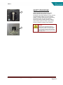
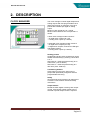
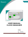
INTRODUCTION
USER MANUAL
CLOCK MANAGER
Vencomatic B.V.
Meerheide 200
5521 DW Eersel
The Netherlands
Phone:
Fax:
e mail:
Website:
User manual clock manager 02012013 (Eng)
+31(0 )497 517380
+31(0) 497 517354
[email protected]
www.vencomatic.com
Pagina 1
INTRODUCTION
INDEX
INTRODUCTION ................................................................................................................................................3
LIABILITY ....................................................................................................................................................
GENERAL....................................................................................................................................................
COPYRIGHT ................................................................................................................................................
GENERAL....................................................................................................................................................
SAFETY REGULATIONS.................................................................................................................................
LEGAL REGULATIONS...................................................................................................................................
HOW TO USE THIS MANUAL? ........................................................................................................................
WHO SHOULD USE THIS MANUAL? ................................................................................................................
MANUAL INFORMATION ................................................................................................................................
SERIAL NUMBER ..........................................................................................................................................
SYMBOLS ...................................................................................................................................................
ADDRESS VENCOMATIC ...............................................................................................................................
1.
4
4
4
5
5
5
6
6
6
6
7
7
SAFETY....................................................................................................................................................9
GENERAL.................................................................................................................................................... 9
SAFETY REGULATIONS............................................................................................................................... 10
SAFETY PROVISIONS ................................................................................................................................. 12
2.
DESCRIPTION .......................................................................................................................................13
CLOCK MANAGER ........................................................................................................................................................................................ 13
3.
OPERATION ..........................................................................................................................................15
SAFETY REGULATIONS............................................................................................................................... 15
EXPLANATION OF THE CLOCK MANAGER .................................................................................................... 15
OPERATING PANEL ....................................................................................................................................................................................... 15
TECHNICAL SPECIFICATIONS ........................................................................................................................................................................ 16
START-UP SCREEN........................................................................................................................................................................................ 17
MAIN PROCESS SCREEN ................................................................................................................................................................................ 17
DIGITAL CLOCKS .......................................................................................................................................................................................... 17
ANALOG CLOCKS ......................................................................................................................................................................................... 18
KEYPAD (NUMERIC) ..................................................................................................................................................................................... 19
KEYPAD (SYMBOLS) ..................................................................................................................................................................................... 19
PASSWORD SCREEN ...................................................................................................................................................................................... 20
LANGUAGE SCREEN ..................................................................................................................................................................................... 20
ALARMS SCREEN .......................................................................................................................................................................................... 21
SHIFT CLOCK PERIODS ................................................................................................................................................................................. 21
SET DIGITAL CLOCK PERIODS ....................................................................................................................................................................... 22
SET ANALOG CLOCK PERIODS ...................................................................................................................................................................... 25
SPECIAL SETTINGS ....................................................................................................................................................................................... 27
DIGITAL CLOCK SETTINGS ............................................................................................................................................................................ 27
DIGITAL CLOCK OPTIONS ............................................................................................................................................................................. 30
ANALOG CLOCK SETTINGS ........................................................................................................................................................................... 31
SAVE SETTINGS ............................................................................................................................................................................................ 32
USB STICK .................................................................................................................................................................................................... 33
PANEL SETTINGS .......................................................................................................................................................................................... 34
DATE&TIME SCREEN .................................................................................................................................................................................... 35
CPU SCREEN ................................................................................................................................................................................................ 35
CONTRAST SCREEN ...................................................................................................................................................................................... 36
NETWORK SCREEN ....................................................................................................................................................................................... 36
GENERAL SCREEN ........................................................................................................................................................................................ 36
WARNINGS ................................................................................................................................................................................................... 37
User manual clock manager 02012013 (Eng)
Pagina 2
INTRODUCTION
INTRODUCTION
CAUTION:
This manual must be read by or to each person, before that person operates, cleans,
repairs, supervises the operation of, or uses this machine in any way.
CAUCION:
Este manual debe ser leido por a cada persona antes de comenzar a operar, limpiar,
reparar, supervisar la operación de, o utilizar esta maquina de cualquier manera.
ATTENTION:
Ce manuel doit être lu par, ou a, toute personne avant qu’elle ne mette en route,
nettoie, répare, supervise le fonctionnement ou utilise cette machine, de quelque
manière que ce soit.
VORSICHT:
Jeder, der diese Maschine bedienen, reinigen, reparieren, überwachen oder auf
irgendeine Weise benutzen soll, muß vorher diese Hinweise lesen oder vorgelesen
bekommen.
ATTENTIE:
Een ieder, die deze machine bedient, reinigt, repareert, controleert of op enige andere
wijze gebruiken zal, dient vooraf deze bedieningsvoorschriften te lezen.
CAUTELA:
Il presente manuale deve essere letto da o ad ogni membro del personale prima che
tale persona operi, pulisca, ripari, diriga il funzionamento o utilizzi la macchina in
qualsiasi modo.
User manual clock manager 02012013 (Eng)
Pagina 3
INTRODUCTION
LIABILITY
Vencomatic BV cannot be held responsible for any costs, damage or personal injury if its system is not
used in accordance with the instructions as described in this manual.
The information provided in this manual is valid for the standard design of the system. Parts of your
system may differ from this standard design.
Since Vencomatic BV is constantly improving its systems it may be possible that there are small
differences between your system and this manual.
Though this manual has been put together with the utmost care, Vencomatic BV cannot accept any
responsibility for costs, damage or personal injury arising from any fault and/or incompleteness in the
content of this document.
GENERAL
This manual contains important information concerning safety, operation, adjustment, maintenance,
cleaning and repair of the Vencomatic BV system. For uncomplicated functioning of the system, read this
manual carefully and work according to the directions in this manual.
Beside the design and the used materials also the operation and maintenance have great impact on the
functioning, the life span and the operational costs of our system. You, as the owner of the system, are
responsible for the execution of maintenance according to the directions and the intervals in this manual.
This manual will help you to gain knowledge to use the system as it should be used: Correct operated
and excellent maintained.
A Vencomatic BV system meets the demands, mentioned in the European machine guideline (CE).
COPYRIGHT
Vencomatic BV ©
This document contains confidential information and information protected by copyright of Vencomatic
BV. Reproduction or transmission of any part of this document to third parties, or the use thereof is only
permitted after express written permission of Vencomatic BV.
All rights rest with Vencomatic BV, Eersel, The Netherlands.
User manual clock manager 02012013 (Eng)
Pagina 4
INTRODUCTION
GENERAL
This manual contains important information concerning safety, operation, cleaning, maintenance and
breakdown remedies.
At all time this manual must be accessible for all personnel working with the system. Keep it in a
permanent place, close to the system. When the manual is lost or damaged, order a new copy as soon as
possible.
The user of the system should read and understand the total user manual before operating, cleaning,
maintaining and repairing the system.
Never change the sequence of procedures as described in this manual.
SAFETY REGULATIONS
Before starting operation, cleaning, maintaining the system or before remedying breakdowns first read
this chapter and chapter Safety.
LEGAL REGULATIONS
-
-
-
All safety directions stated in this manual must be observed.
Along with the safety regulations in this chapter the instructions of the qualified trade organization
of your country must be observed to avoid accidents.
Before starting to repair or maintain the machine always consult your safety manager to discuss if
a work permit is required for this job.
All safety devices in the machine and the safety indications mentioned in this manual are
conditions to control the machine safely. The owner and his qualified personnel are in the end the
ones responsible for the safe use of the machine.
The owner is responsible for the ability of the qualified personnel to perform its duties according
to the safety measures.
Technical changes, which influence the safety working of the machine, may only be executed by
the service department of Vencomatic.
Do not change controls, and/or PLC programs, without written permission from Vencomatic
because this may affect the safety of the machine.
Only use genuine Vencomatic parts or CE-certified parts for replacement.
Vencomatic cannot be held responsible for any consequential damages to the system or other
installations that were caused by technical changes, unprofessional maintenance and repairs on
our system, which were executed by the customer.
Warranty becomes invalid when consequential damages to the system, caused by technical
changes, unprofessional maintenance and repairs, were executed by the customer.
DANGER!
Failure to obey legal regulations may result in permanent personal injury or death.
ATTENTION!
Failure to obey legal regulations may result in damage to the system.
User manual clock manager 02012013 (Eng)
Pagina 5
INTRODUCTION
HOW TO USE THIS MANUAL?
The manual is constructed to provide a maximum amount of information with a minimum amount of
searching. The key to easy reference is the Table of contents. Familiarize yourself with it and you won’t
have any trouble locating information from any area of machine.
WHO SHOULD USE THIS MANUAL?
Owner:
The owner (contractor, concern) is the person that owns or hires the machine and puts this machine into
production. The owner must take care that the users of the system will read the manual.
Operator:
The operator is the person who operates the system as ordered by the owner. The operator must read
the chapters Introduction, Safety, Machine description, Operation, Cleaning.
Professional:
A professional is someone who can assess the duties appointed to him on account of his education,
knowledge and experience and who can assess the dangers attached, thereby avoiding these dangers.
Maintenance engineer:
The maintenance engineer is the professional who is deemed qualified by the owner to perform certain
duties. The qualification only applies to those assigned duties. The maintenance engineer must read the
total manual.
MANUAL INFORMATION
Machine type:
Rev01:
Clock Manager
05102012
SERIAL NUMBER
Each machine has a unique serial number printed on the machine tag, which can be found on the
electrical cabinet. Write down this serial number to have it available when contacting the Vencomatic
service department.
Example
User manual clock manager 02012013 (Eng)
Pagina 6
INTRODUCTION
SYMBOLS
Symbols are used in the manual when special attention/caution is required while working on the system.
The special symbols and their meaning are depicted in the below table.
Symbol:
Meaning:
DANGER!
This symbol is used when instructions should be followed to the letter. If not they may result in permanent personal
injury or death.
CAUTION!
This symbol is used when instructions should be followed to the letter. If not they may result in permanent personal
injury.
ATTENTION!
This symbol is used when instructions should be followed to the letter. If not they may cause damage to the
system.
NOTE!
This symbol advises to use edible products and to work in a hygienically way. Disregarding this advice may cause
illness.
TIP!
This symbol is used as a helpful hint to simplify the execution of certain tasks.
ADDRESS VENCOMATIC
Vencomatic B.V.
Meerheide 200
5521 DW Eersel
The Netherlands
Phone: +31(0 )497 517380
Fax: +31(0) 497 517354
e mail: [email protected]
Website: www.vencomatic.com
User manual clock manager 02012013 (Eng)
Pagina 7
SAFETY
1. SAFETY
GENERAL
Only persons meeting the following requirements are authorized to work with the system. These
persons should be:
- Skilled and specifically trained for their duties.
- Familiar with the contents of this manual.
- Familiar with the locations of the emergency buttons and other safety devices.
- 18 years old or above.
- Familiar with the national and regional regulations regarding safety.
These persons should have reached the minimum legal age required to perform this work.
These persons are NOT under influence of any drug, medicine or alcoholic drink.
DANGER!
Keep children and incompetent persons away from the system!
The system is only to be used for the purpose it was designed for. See the chapter Machine
description for details.
User manual clock manager 02012013 (Eng)
Pagina 9
SAFETY
SAFETY REGULATIONS
Do not use the system when safety devices have been removed. This system may contain sharp
edged parts, moving parts and rotating parts.
When protective covers are removed, sharp edges and pinch points may be exposed. Use extreme
caution and avoid touching or striking these areas with your hands or body because they may cause
injuries.
Do not enter parts of your body or objects into openings in the system. This may lead to serious
physical injury or damage to the system. It is dangerous to be in, on or under the system while it is
operational.
Loosely hanging clothing, wide sleeved clothing, ties, chains or rings are prohibited. Long hair should
be worn tied back.
Make sure that there is sufficient light around the machine.
Do not touch or come near moving or rotating parts. Physical contact with these parts is dangerous.
Do not stand or walk on any of the system parts.
Do not work alone on the system. At least one other person should be present
Before starting to clean, maintain or inspect the machine or before remedying breakdowns follow the
steps mentioned below:
- Switch off the machine and secure it against accidental switching on.
- Post “Do not switch on” warning sign on the main switch:
- Operate the nearest emergency button.
- Make sure that no components are moving.
Before switching on the machine, you must check the following:
- All safety devices are in place and are functioning.
- No other persons are in, underneath or above the system.
- No tools or objects are in the system.
- No other persons are at risk.
Do not use water to clean electricity cabinets and other electronic components.
For save and easy operation keep the area and floor around the machine clean, free of oil, grease or
obstacles. Remove superfluous fat and greasing oil after greasing duties.
When an extension cable is used for power supply, make sure that the cable diameter in relation to
the length of the cable is correct. Make sure the cable is completely unrolled
Manual activation of safety switches is forbidden.
When the safety devices are put out of operation, the machine must first be switched off and secured
against accidental switching on.
Work inside the electrical cabinet may only be undertaken by skilled personnel like Vencomatic
service engineers or its dealer’s service engineers.
Always switch off the main switch before opening electrical cabinets.
After switching off the main switch, parts inside the electrical cabinet remain live for approximately 1
minute. The frequency inverters may hold a high voltage charge during this time. Do not touch parts
inside the electrical cabinet as long as displays of frequency inverters are on.
User manual clock manager 02012013 (Eng)
Pagina 10
SAFETY
Several parts inside the electrical cabinet maintain voltage even when the main switch is turned off
(main switch, main power supply, terminals for egg collecting belts, etcetera).
DANGER!
Failure to obey safety regulations may result in permanent personal injury or death.
ATTENTION!
Failure to obey safety regulations may result in damage to the system.
User manual clock manager 02012013 (Eng)
Pagina 11
SAFETY
SAFETY PROVISIONS
1
Before operating the machine the safety
devices must be checked for correct
functioning. Also the protective covers must be
mounted before starting to use the system.
Repair or replace safety devices before using
the system if they do not work properly.
Never rely solely on safety devices. Always
switch off the system and lock up the power
source (1) before working on the machine.
2
User manual clock manager 02012013 (Eng)
DANGER!
Protective covers safeguard dangerous
machine areas. These covers are of utmost
importance to operate the machine safely.
Never operate the machine when protective
covers are removed because serious injury or
death may occur!
Pagina 12
MACHINE DESCRIPTION
2. DESCRIPTION
CLOCK MANAGER
The clock manager controls digital outputs and
analog outputs with free programmable clock
(start-stop) periods. A maximum of 24 clock
periods are available per digital or analog
output.
Minimum clock period time is 1 minute.
Minimum time between two clock periods is 1
minute.
A basic clock manager model consist of
- 12 digital clock outputs (On..Off).
- 4 analog clock outputs (0..10VDC).
A extended clock manager model consist of
- 12 digital clock outputs (On..Off).
- 6 digital clock outputs, reserved for LED-light
and feeding options.
- 8 analog clock outputs (0..10VDC).
Shifting periods
All digital and analog clock period times can be
shifted simultaneously by entering a shift value
X or Y.
Shift value X = shifts the period time(s) to an
earlier time. (0.00..9.00hour)
Shift value Y = shifts the period time(s) to a
later time. (0.00..9.00hour)
Customizing buttons
Clock buttons on the touch panel can be
pimped with predefined pictograms and free
programmable text string.
Safety
Above descript clock manager can take part of
a machine. Check above mentioned safety
instructions.
Output models
Beside the basic digital or analog clock output
control, several other output models can be
selected if special output control is required.
User manual clock manager 02012013 (Eng)
Pagina 13
MACHINE DESCRIPTION
Digital clock output models
Several clock output models are available
for all digital clock outputs:
7) Clock is OK
Output is on if clock manager has been
powered on and no main alarms are active.
1) Basic digital clock.
Between the entered period-start and periodstop the clock output is on.
____________________________________
2) Nest
One clock output pulse is generated the
moment the clock output goes on.
Used to warn the chickens the nest opens.
Three clock output pulses are generated the
moment the clock output goes off.
Used to remove eggs from nest bottom.
Analog clock
Between the entered period-start and periodstop the clock output increases or decreases to
an analog end value (between 0%..100%). The
analog end value is free programmable.
Save all clock settings
All clock settings can be saved in a file or on
an USB stick.
Restore all clock settings
All clock settings can be restored back from a
file or USB stick.
3) Pulse
Clock output pulse is generated the moment
the clock output goes on. Pulse length can be
set between 1..3600 sec. (max. 1 hour)
4) Pulse(speed)
Clock output pulse is generated the moment
the period output goes on. Feeding time is
automatic calculated depending on the speed.
Used for chain feeding systems where
speed(%) and runtime of the chain are
automatically calculated. Resulting the chain
always runs its total length (Lmax).
5) Clock + Speed
Between the entered period-start and periodstop the clock output is on. At the same time
feeding speed (%) can be controlled directly.
Remote control
Clock computer screen can be remotely
controlled through VNC (client) technology.
VNC server IP address = 10.0.2.1 (default)
Password (read only) = r (remote view
possible)
Password (write) = w (remote operation
possible)
Basic hardware
The basic clock manager consists of:
1 5.7” color touch screen (including PLC
backup battery and Compact Flash
card)
2 Communication module
3 Output module (12 x 24VDC, 0.5A)
4 Analog output module (4 x 0..10VDC,
10mA)
The extended clock manager consists of:
1 5.7” color touch screen (including PLC
backup battery and Compact Flash
card)
2 Communication module
3 Output module (12 x 24VDC, 0.5A)
4 Output module (6 x 24VDC, 0.5A)
5 2 Analog output modules (4 x
0..10VDC, 10mA)
Used for chain feeding systems where speed
and runtime both can be controlled manually.
6) Light active (analog x)
Output goes on if analog x clock output value
is higher than its minimum set point (%).
Used to shut-down light amplifiers if their
minimum set point has been reached.
User manual clock manager 02012013 (Eng)
Pagina 14
OPERATION
3. OPERATION
SAFETY REGULATIONS
Before starting operation, cleaning, maintaining the system or before remedying breakdowns first read
the chapters Introduction and Safety.
EXPLANATION OF THE CLOCK MANAGER
OPERATING PANEL
The clock manager consist of a touch panel and a PLC part. The PLC controls the output modules.
The touch panel shows information about the status of the system. By pressing on certain parts of the
touch panel, depending on the chosen button or screen, the system is controllable, settings can be
changed or information becomes visible on the screen.
DANGER!
Although a lot of safety measures are built into the control of the system, Vencomatic cannot guarantee that no
dangerous situations will occur. Before you start the system, make sure no persons are in danger.
User manual clock manager 02012013 (Eng)
Pagina 15
OPERATION
Start and stop outputs:
The Clock manager controls digital and analog outputs. When the real-time clock of the clock manager
reaches the period-start of one of the clocks, the digital or analog output of that clock becomes active.
When the period-stop has been passed the clock output is de-activated.
DANGER!
Switch off the clock manager system when working on the machine.
Switch off the system and secure it against accidental switching on.
If a system is not switch off, it can start automatically when outputs are activated by the clock computer.
TECHNICAL SPECIFICATIONS
The technical specifications of your system may differ slightly from the descriptions in this manual.
Because of this the data in the technical specifications may be incorrect and/or incomplete for your
system.
For complete and exact data, see the electrical drawing and the machine tag on your system.
Electrical data:
Power panel:
Connection voltage
: 24V dc
Pre fuse
: 5 Amp, fast blowing
Maximum current
: 5 Amp
Maximum voltage deviation
: ±15%.
Electrical protection
: IP65 (front side) / IP20 (back side)
The pin's connection to the functional ground (e.g. switching cabinet) should be as
short as possible. We recommend using the largest possible conductor cross
section on the supply plug.
Output modules:
Connection voltage
Pre fuse
Maximum current
Maximum voltage deviation
Electrical protection
:
:
:
:
:
24V dc
10 Amp, slow blowing
10 Amp
±15%.
IP20
Environment:
The climate around the clock manager must have a normal working temperature (+10ºC to 30ºC).
During transport and storage the temperature of the system should remain in between 0°C and 45°C.
The system is not suitable for outdoor use and should not be used in a surrounding containing items
having a high flash point or an explosive nature.
Environment consequences:
Dismantling and disposal of the system must be carried out by a suitable disposal company, which
has the required licenses and permits for the state or the country concerned. Dismantled materials
should be sorted for disposal according to local rules and regulations that may apply.
Separate all materials like oil and lubrication fluids and discharge them as chemical waste.
User manual clock manager 02012013 (Eng)
Pagina 16
OPERATION
START-UP SCREEN
After switching on the system main switch, the
start-up screen appears. Wait till button (1)
appears (approx. 1 minute).
After touching button (1) main process screen
100 appear.
MAIN PROCESS SCREEN
1
Screen: 100
Alarm message line (2):
On top of all screens, alarms or warnings
appear when the system needs assistance.
Alarm button (3)
If this alarm button is continuous red, it
indicates there is an alarm. If the button is
blinking red, it indicates there is a warning.
After touching the button the alarm screen
appears.
ATTENTION!
Touch the panel only if button (1) appears.
Otherwise the calibration screen starts up.
2
3
4
See alarm and warnings in appendix for
possible alarms and warnings that may occur.
After touching button (4) digital clocks screen
101 appear.
Shift all clock periods (5):
After touching button (5) shift values X and Y
can be set. Password level 1 or higher.
Special settings (6):
After touching button (6) special main settings
screen 500 appear. Password level 3 or
higher.
5
6
Password (7):
Push password button for changing password
levels. There are 4 password levels. Level 1,
level 2, level 3 and highest level 4.
7
8
DIGITAL CLOCKS
Screen: 101
Digital clock buttons (8):
Each button represents a digital clock output.
Button status,
White: Digital clock output is switched off.
Green: Digital clock output is switched on.
Push button to status or change digital clock
settings. For changing settings set password
level 1 or higher.
9
User manual clock manager 02012013 (Eng)
Analog clock buttons (9):
After touching button (9) analog clocks screen
102 appear.
Pagina 17
OPERATION
10
ANALOG CLOCKS
Screen: 102
Analog clock buttons (10):
Each button represents an analog clock
output.
Button status,
White: Analog clock output is 0VDC (0VDC =
0%)
Green: Analog clock output is between 0 and
10 VDC. (10 VDC = 100%)
Push button to status or change analog clock
settings. For changing settings set password
level 1 or higher.
User manual clock manager 02012013 (Eng)
Pagina 18
OPERATION
KEYPAD (NUMERIC)
After touching a yellow numeric input window
on one of the screens, the numeric keypad
appears. Enter a correct value and confirm it
with the V button (13). Cancel (11). Back
space (12).
11
12
13
KEYPAD (SYMBOLS)
13
After touching a yellow input window on one of
the screens, the keypad appears. Enter a
correct value and confirm it with the V button
(13). Capital letter (14). Delete text (15).
15
14
User manual clock manager 02012013 (Eng)
Pagina 19
OPERATION
31
PASSWORD SCREEN
30
32
29
Here you can enter your password or select a
language. Depending on the operating level
you get the possibility to change settings of the
system. Passwords will be handed over to
certain dedicated persons within your
company.
35
Language selection screen 820 will appear if
button (29) is pushed.
33
The level window (30) shows the current
operating level. For the lower operating levels
the passwords are also visible. After touching a
visible password (31), a keypad pops up in
which it is possible to change the password.
After touching the password window (32) a
keypad appears (33). After entering the correct
password and confirming it with the V button
(34) the operating level changes.
34
Push button (35) to reset active password
level. Password level gets 0 again.
LANGUAGE SCREEN
Screen: 820
In this screen it is possible to select the
language of the touch panel.
User manual clock manager 02012013 (Eng)
Pagina 20
OPERATION
ALARMS SCREEN
21
20
22
The Alarms current screen shows all present
alarms from the system.
By touching the up- or down arrows (20) it is
possible to scroll through the alarm list.
An active alarm is colored red.
st
By touching the R button (21) the 1 time, the
alarm is reset. When the breakdown causing
the alarm is not solved, the alarm immediately
pops-up again.
After touching the alarm history button (22) the
alarm history screen appears.
23
Previous (23):
After touching this arrow button the previous
screen appears.
Submenu Alarm history:
The Alarm history screen shows the history of
all alarms from the system.
By touching the up- or down arrows (25) it is
possible to scroll through the alarm list.
25
SHIFT CLOCK PERIODS
26
Push button (26) to enter shift clock periods.
Enter shift X period and shift X values in yellow
input windows (26) (27) to shift all digital and
analog clock periods simultaneous.
Shift periods earlier (27):
between 0.00 hour and 9.00 hour. (0.00=no
shifting)
27
28
Shift periods later (28):
between 0.00 hour and 9.00 hour. (0.00=no
shifting)
Depending on the shift period types selected,
period-start, period-stop or no period shifts will
take place.
Changes allowed if password level 1 or higher.
User manual clock manager 02012013 (Eng)
Pagina 21
OPERATION
39
SET DIGITAL CLOCK PERIODS
Push button (39) to select a digital clock.
A total of 24 periods can be set per clock.
Minimum clock period time is 1 minute.
Changes allowed if password level 1 or higher.
40
43
41
Clock status (40):
-On
Digital clock is switched on
-Off
Digital clock is switched off
-(End of day) Current day clock periods are
ready.
-(Calculate)
Calculate the clock periods.
-(01:28:54)
Remain time (hh:mm:ss)
Clock period (41): Next or active clock period.
42
Shift periods (42): X,Y shift times (hh:mm).
44
<
45
Period amount (43):
Enter amount of clock periods.
Clock periods:
The clock periods are numbered from top to
bottom.
Clock period 1 (44)
Clock period 2 (45) Up till period 24
Start and stop clock period input fields:
Period start time (46) and period stop time
(47).
46
47
Maximum clock range of all periods is 23:59
hours per day.
48
Shift period types input field (48):
No period shift
ATTENTION!
- Clock periods always are activated one by
one. Starting from period #1, followed by period
#2 etc.
- When shifting, at least one period-stop must
stay in its current day.
- If a clock period start time is set greater than
period stop time all shift period types are
forced to
49
50
Complete period shifts x hour.
Complete period shifts y hour.
Period start shifts x hour. Period stop
is fixed.
Period stop shifts y hour. Period start
is fixed.
Period start shifts x hour and period
stop shifts y hour.
Cancel:
Push button (49) to set previous start-stop
clock period times and shift types back.
Confirm:
Push button (50) to save new start-stop clock
period times and shift types.
The confirm and cancel buttons now will
disappear.
User manual clock manager 02012013 (Eng)
Pagina 22
OPERATION
51
An uninterrupted day pass (23.59 to 0.01) can
be achieved if the start period (51) is greater
than the stop period (52).
All shift types at each period now will
52
automatically be set to
“no period shift” .
-------------------------------------------------------------If basic digital clock or Nest clock output
models were chosen above mentioned
screens will appear.
53
-------------------------------------------------------------If a “Pulse” clock output model was chosen,
next screen will appear.
Pulse length (53):
Clock output pulse is generated the moment
the clock output goes on. Pulse length can be
entered between 1..3600 sec. (max. 1 hour)
54A
------------------------------------------------------------If a “Pulse (speed)” clock output model was
chosen, next screen will appear.
54
Speed (54):
Clock output pulse is generated the moment
the period output goes on. Feeding time (54A)
is automatic calculated depending on the
speed (54).
Resulting the chain always runs its total length
(Lmax).
Feeding time (min) = (Runtime feed belt at
100% x 100) / Speed (%).
Go to Digital Clock Options Screen 680 to set:
Runtime feed belt at 100%.
User manual clock manager 02012013 (Eng)
Pagina 23
OPERATION
-------------------------------------------------------------If a “Clock + Speed” clock output model was
chosen, next screen will appear.
54
Speed (54):
Enter speed, feed chain must run.
User manual clock manager 02012013 (Eng)
Pagina 24
OPERATION
55A
SET ANALOG CLOCK
PERIODS
Push button (55A) followed by
button to
select an analog clock. A total of 24 period
slopes can be set per clock. Minimum clock
period slope time is 1 minute.
Changes allowed if password level 1 or higher.
Clock periods:
The clock periods are numbered from top to
bottom.
Clock period 1 (55)
Clock period 2 (56) Up till period 24
55
56
57
58
59
60
Start and stop clock period input fields:
Period start time (57) and period stop time(58).
Percentage input field:
Final analog end value (59) if period stop time
has been reached. Output range 0..100%
(0..10VDC)
Shift period types input field (60):
No period shift
Complete period shifts x hour.
Complete period shifts y hour.
Period start shifts x hour. Period stop
is fixed.
Period stop shifts y hour. Period start
is fixed.
Period start shifts x hour and period
stop shifts y hour.
ATTENTION!
- Clock periods always are activated one by
one. Starting from period #1, followed by period
#2 etc.
- When shifting, at least one period-stop must
stay in its current day.
- If a clock period start time is set greater than
period stop time all shift period types are
forced to
User manual clock manager 02012013 (Eng)
Pagina 25
OPERATION
62
63
Cancel:
Push button (62) to set previous start-stop
clock period times and shift types back.
Confirm:
Push button (63) to save new start-stop clock
period times and shift types.
An uninterrupted day pass (23.59 to 0.01) can
be achieved if the start period (64) is greater
than the stop period (65).
64
65
All shift types at each period now will
automatically be set to
User manual clock manager 02012013 (Eng)
“no period shift”
Pagina 26
OPERATION
25
SPECIAL SETTINGS
For special setting press button (25). Panel
settings button (26) and Save settings button
(27) are activate if password level is 2 or
higher. Clock settings button (28) followed by
analog clock(30) or digital clock (29) buttons
are activated if password level is 4.
DIGITAL CLOCK SETTINGS
26
27
28
29
30
Push button (29) followed by button (31) for
changing digital clock settings.
Several clock output models (32) can be
selected.
1) Not used. Clock is not used.
2) Basic digital clock.
Between the entered period-start and periodstop the clock output is on.
3) Nest
One clock output pulse is generated the
moment the clock output goes on.
Used to warn the chickens the nest opens.
Three clock output pulses are generated the
moment the clock output goes off.
Used to remove eggs from nest bottom.
Go to Digital Clock Options screen 680 to set
the pulse times.
4) Pulse
Clock output pulse is generated the moment
the clock output goes on. Pulse length can be
set between 1..3600 sec. (max. 1 hour)
31
5) Pulse(speed)
Clock output pulse is generated the moment
the period output goes on. Feeding time is
automatic calculated depending on the speed.
Used for chain feeding systems where
speed(%) and runtime of the chain are
automatically calculated. Resulting the chain
always runs its total length (Lmax).
32
33
34
Go to Digital Clock Options screen 680 to set
the run time feed belt at 100%.
ATTENTION!
With this output model selected, also a
combined analog clock output model (2):
Feeding speed, must be selected.
User manual clock manager 02012013 (Eng)
Pagina 27
OPERATION
6) Clock + speed
Between the entered period-start and periodstop the clock output is on.
Feeding speed (%) can be controlled directly.
Used for chain feeding systems where speed
and runtime both can be controlled manually.
ATTENTION!
With this output model selected, also a
combined analog clock output model (2):
Feeding speed, must be selected.
7) Light active (analog x)
Output goes on if analog x clock output value
is higher than its minimum set point (%).
Used to shut-down LED-light amplifiers if their
minimum outputs have been reached.
Go to Digital Clock Options screen 680 to set
the Minimum output percentage (default 5%).
ATTENTION!
With this output model selected, the digital
clock will not be displayed on the screen.
8) Clock is OK
Output is on if clock manager has been
powered on and no main alarms are active.
ATTENTION!
With this output model selected, the digital
clock will not be displayed on the screen.
User manual clock manager 02012013 (Eng)
Pagina 28
OPERATION
Water nipple
Eau pipette
Wasser Nippel
Water valve
Vanne d'eau
Wasserventil
Feed chain
Chaîne alim.
Futter Kette
Feed gutter
Mangeoire
Futtertrog
Feed pan
Assiette
Futterschale
Feeding
d'aliment
Füttern
Auger
Vis sans fin
Schnecke
Fan
Ventilateur
Fan
Belt
Tapis
Band
Nest
Pondoir
Nest
Gate
Porte
Tor
Winch
Treuil
Winde
Light
Éclairage
Licht
Egg
Œuf
Ei
Clock
Horloge
Uhr
Belt pulse
Impulsion tapis
Band Puls
User manual clock manager 02012013 (Eng)
Name (33):
Free programmable text string. Maximum 10
characters.
Pictogram (34):
Pictogram selection. Up till 16 different clock
button pictograms can be selected.
Pagina 29
OPERATION
36
DIGITAL CLOCK OPTIONS
Push button (36) for changing digital clock
option settings. Screen 680 will appear.
37
38
39
User manual clock manager 02012013 (Eng)
Nest
One clock output pulse (37) is generated the
moment the clock output goes on.
Used to warn the chickens the nest opens.
Three clock output pulses (38) are generated
the moment the clock output goes off.
Used to remove eggs from nest bottom.
Lights active (analog x) (39)
Can be entered here. (Default 5%)
Pagina 30
OPERATION
ANALOG CLOCK SETTINGS
40
Push button (40) for changing analog clock
settings.
Several clock output models (41) can be
selected.
1) Not used.
Clock is not used.
41
42
2) Basic analog clock.
Between the entered period-start and periodstop the clock output increases or decreases
to an analog end value (between 0%..100%).
The analog end value is free programmable.
43
Name (42):
Free programmable text string. Maximum 10
characters.
Pictogram (43):
Pictogram selection. Up till 16 different clock
button pictograms can be selected. (see
pictograms Digital Clock Settings)
User manual clock manager 02012013 (Eng)
Pagina 31
OPERATION
91
92
93
94
90
95
SAVE SETTINGS
Screen: 700
In this menu it is possible to make, save, open
or delete a machine settings file.
A machine settings file is a file which contains
all the current clocks settings and more.
Create (90):
After touching this button, a keypad pops up in
which it is possible to enter a file name. After
confirming the name with the V- button, the file
is created and its name appears in the file
name list (91)
ATTENTION!
By default the machine_data.csv file always
will be created at first startup.
Creating a file takes approx. 40 seconds.
Save (92):
After selecting a file name from the file name
list and touching this save button, all the
current clock settings and more are stored in
this file.
ATTENTION!
Saving a file takes approx. 40 seconds.
Download (93):
After selecting a file name from the file name
list and touching this button, all clock settings
and more of this file are downloaded.
ATTENTION!
After download has been completed the new
clock settings will take effect immediately.
Try to download new clock settings if all lights
are off and today’s feeding has been finished.
Download a file takes approx. 40 seconds.
Delete (94):
After selecting a file name from the file name
list and touching this button, this file is deleted.
USB (95):
After touching this button you will enter the
USB stick submenu in which it is possible to
load or store machine setting files.
User manual clock manager 02012013 (Eng)
Pagina 32
OPERATION
USB STICK
99
100
98
97
Screen: 710
Inside the operating panel, on the rear side of
the touchpanel, it is possible to plug in an USB
stick (96). To store machine setting files on an
USB stick, or to load Machine setting files from
the USB stick, first plug in the USB stick.
After touching the Directory button (97) on the
left side of the screen, all the machine setting
files of the system appear in the left list.
After touching the Directory button (98) on the
right side of the screen, all the machine setting
files on the USB stick appear in the right list.
After selecting a file in the left list and touching
the right arrow button (99), this file is stored on
the USB stick.
After selecting a file in the right list and
touching the left arrow button (100), this file is
loaded from the USB stick.
96
User manual clock manager 02012013 (Eng)
Pagina 33
OPERATION
PANEL SETTINGS
Screen: 800
In this menu the user of the system is able to
change touchpanel settings using submenus.
This submenu is not available for the operator
and some of the screens in this submenu are
also not available for the supervisor.
Date&Time:
After touching this button the Date&Time
screen appears. In this screen it is possible to
set the correct date and time.
CPU:
After touching this button the CPU screen
appears. This screen shows information about
the status of the control system.
Contrast:
After touching this button the Contrast screen
appears. In this screen it is possible to adjust
the contrast, the brightness and the orientation
of the display.
Network:
After touching this button the Network screen
appears. In this screen it is possible to adjust
the communication between the clock
manager and (LAN intranet) an external
computer.
General:
After touching this button the General screen
appears. In this screen it is possible to adjust
the communication between the machine and
(via the internet) an external computer.
User manual clock manager 02012013 (Eng)
Pagina 34
OPERATION
DATE&TIME SCREEN
Screen: 831
After touching year, month, day, hour or minute
a keypad appears. Enter the correct date and
time and confirm this with the
button.
ATTENTION!
Panel clock can shift approx. 2 seconds per
week with respect to the atomic clock.
DST (winter/summer time) is not automatically
adjusted.
CPU SCREEN
Screen: 832
This screen shows information about the status
of the control system.
Serial number:
Here the serial number of the CPU is
displayed. During contact with a Vencomatic
service engineer to solve a breakdown, you
may be asked to pass on this serial number.
Temperature CPU/ENV:
Here the temperature of the CPU (Central
Processing Unit) and its surrounding
temperature is displayed.
Whenever the temperature rises too high, a
message appears on the screen and the
cabinet of the CPU needs to be cooled
immediately.
Backup battery status:
The back-up battery status shows the status of
the battery. When the battery becomes
exhausted, not OK appears. In that case do
not power off the system and contact
Vencomatic for the exchange procedure of the
battery.
Power up cycles:
The amount of power up cycles (switching ON
the system) is displayed here.
Operation hours:
The time that the system was running
production.
User manual clock manager 02012013 (Eng)
Pagina 35
OPERATION
110
CONTRAST SCREEN
111
With the contrast buttons (110) it is possible to
adjust the contrast of the display. (only panel 1
is used (left))
With the brightness buttons (111) it is possible
to adjust the brightness of the display. (only
panel 1 is used (left))
After touching the orientation button (112) you
can calibrate the touch panel part of the
display. Dots appear on the screen. Touch
these dots with a pointed (but not sharp!)
object (113). After touching the last dot, the
touch panel part of the display is calibrated.
112
113
ATTENTION!
It is forbidden to press on the Touch Panel
with sharp objects because this may also
damage the touch Panel.
TIP!
The touch panel is calibrated in the factory.
Because of this, normally it is not necessary
to calibrate the touch panel.
NETWORK SCREEN
In this screen it is possible to enter the IP
addresses to be able to communicate with an
external computer via an Internet connection.
Normally these addresses are entered by
Vencomatic engineers and are for information
only.
In case it is necessary to change these
addresses ask your network administrator to
do this.
GENERAL SCREEN
System Reset
After touching the blue reset button, the factory
settings of the system are restored. Please
power down the panel first so settings will take
effect.
Ignore IO model not OK alarm.
No = <Default>. Do not ignore IO module
alarm.
Yes = Ignore IO module alarm (Used if no IO
modules are connected, for example a demo
model).
User manual clock manager 02012013 (Eng)
Pagina 36
APPENDIX
WARNINGS
Warning / alarm
Backup battery CPU is empty.
CPU batterie de secours est vide
Backup-Batterie CPU ist leer
IO module number 1 not OK
Numéro IO_module 1 pas OK
IO_module Nummer 1 nicht OK
IO module number <x> not OK
Numéro IO_module <x> pas OK
IO_module Nummer <x> nicht OK
Temperature x°C in CPU ENV too high /
Temperature x°C CPU sink too high.
Solution
In that case do not power off the system and
contact Vencomatic for the exchange
procedure of the battery.
Check bus connection between B&R PLC en
B&R PLC Output modules.
Check for 24VDC on B&R PLC Output
modules
Check if given module number <x> has a
physical correct bus connection.
Reposition module again if needed.
Ambiant temperature B&R PLC to high.
Lower temperature inside electrical cabinet
Contact Vencomatic.
Température x°C dans la CPU ENV trop
élevé
Température x°C CPU évier trop élevé
Temperatur x°C CPU zu hoch
Temperatur x°C in CPU ENV zu hoch
Digital clock <x> periods exceed 24 hours.
Change periods!!
Clock <x> reduce total period length.
Horloge numérique <x> périodes dépasser
24 heures. Changer périodes!!
Digitale Uhr <x> Perioden überschreiten 24
Stunden. Änder Perioden!!
Digital clock <x> start period > stop period.
Shift types are forced to |0|.
Only as information. Press
button
at alarm screen to remove message.
Horloge numérique <x> start période > stop
période. Types de changement sont obligés
de |0|.
Digitale Uhr <x> start Periode > stop
Periode. Verschiebungs typen sind
gezwungen zu |0|.
All digital clock <x> periods x[--] are shifted
in to the previous day. Change periods!!
Change a clock <x> period. Always one of
the periods must be active in the current day.
Tout horloge numérique <x> périodes x[--]
sont décalées dans la journée précédente.
Changer périodes!!
Alle digital Uhr <x> Perioden x[--] sind in den
User manual clock manager 02012013 (Eng)
Pagina 37
APPENDIX
vorhergehenden Tag verschoben. Änder
Perioden!!
All digital clock <x> periods [--]y are shifted
in to the next day. Change periods!!
Change a clock <x> period. Always one of
the periods must be active in the current day.
Tout horloge numérique <x> périodes [--]y
sont décalés pour le lendemain. Changer
périodes!!
Alle digital Uhr <x> Perioden [--]y sind in den
nachste Tag verschoben. Änder Perioden!!
Analog clock<x> periods exceed 24 hours.
Change periods!!
Clock <x> reduce total period length.
Horloge analogique <x> périodes dépasser
24 heures. Changer périodes!!
Analog Uhr <x> Perioden überschreiten 24
Stunden. Änder Perioden!!
Analog clock <x> start period > stop period.
Shift types are forced to |0|.
Only as information. Press
button
at alarm screen to remove message.
Horloge analogique <x> start période > stop
période. Types de changement sont obligés
de |0|.
Analog Uhr <x> start Periode > stop Periode.
Verschiebungs typen sind gezwungen zu |0|.
All analog clock <x> periods x[--] are shifted
in to the previous day. Change periods!!
Change a clock <x> period. Always one of
the periods must be active in the current day.
Tout horloge analogique <x> périodes x[--]
sont décalées dans la journée précédente.
Changer périodes!!
Alle analog Uhr <x> Perioden x[--] sind in
den vorhergehenden Tag verschoben. Änder
Perioden!!
All analog clock <x> periods [--]y are shifted
in to the next day. Change periods!!
Change a clock <x> period. Always one of
the periods must be active in the current day.
Tout horloge analogique <x> périodes [--]y
sont décalés pour le lendemain. Changer
périodes!!
Alle analog Uhr <x> Perioden [--]y sind in
den nachste Tag verschoben. Änder
Perioden!!
User manual clock manager 02012013 (Eng)
Pagina 38