1
Instruction Manual
Multi-function Keypad "TP-G1"
Thank you for purchasing our Multi-function Keypad TP-G1.
• This product is designed to remotely control the FRENIC-Eco series of inverters. Read through this
instruction manual and be familiar with the handling procedure for correct use.
• Improper handling blocks correct operation or causes a short life or failure.
• Deliver this manual to the end user of the product. Keep this manual in a safe place until the Multi-function
Keypad is discarded.
• For the usage of inverters and optional equipment, refer to the instruction manuals prepared for the
FRENIC-Eco series of inverters and its optional equipment.
Fuji Electric FA Components & Systems Co., Ltd.
INR-SI47-0890-E
Copyright © 2004 Fuji Electric FA Components & Systems Co., Ltd.
All rights reserved.
No part of this publication may be reproduced or copied without prior written permission from Fuji Electric FA
Components & Systems Co., Ltd.
All products and company names mentioned in this manual are trademarks or registered trademarks of their
respective holders.
The information contained herein is subject to change without prior notice for improvement.
Preface
Thank you for purchasing our Multi-function Keypad "TP-G1."
By installing a TP-G1 Multi-function Keypad directly on a FRENIC-Eco series inverter as an attached keypad or
connecting them together using an optional Remote Operation Extension Cable (CB-5S, CB-3S, or CB-1S,
depending on the distance), you can operate the inverter locally or remotely. In either mode, you can, in the same
way as with a standard built-in keypad, run and stop the motor, monitor the running status, and set the function
codes. In addition, you can perform "data copying": You can read function code data from an inverter, copy (write)
it into another inverter, or verify it.
Before installing and using the Multi-function Keypad, read through this manual in conjunction with the
FRENIC-Eco Instruction Manual and familiarize yourself with its proper use. Improper use may prevent normal
operation or cause a failure or reduced life of the inverter.
Related Publications
Listed below are other publications on the FRENIC-Eco to be consulted in conjunction with this manual as
necessary.
• FRENIC-Eco User's Manual
(MEH456)
• RS485 Communication User's Manual
(MEH448a)
• Catalog
(MEH442)
• FRENIC-Eco Instruction Manual
(INR-SI47-0882-E)
• RS485 Communications Card "OPC-F1-RS" Installation Manual
(INR-SI47-0872)
• Relay Output Card "OPC-F1-RY" Instruction Manual
(INR-SI47-0873)
• Mounting Adapter for External Cooling "PB-F1" Installation Manual (INR-SI47-0880)
• Panel-mount Adapter "MA-F1" Installation Manual
(INR-SI47-0881)
• FRENIC Loader Instruction Manual
(INR-SI47-0903-E)
The materials are subject to change without notice. Be sure to obtain the latest editions for use.
Safety precautions
Read this manual thoroughly before proceeding with installation, connections (wiring), operation, or maintenance
and inspection. Ensure you have sound knowledge of the device and familiarize yourself with all safety
information and precautions before proceeding to operate the inverter.
Safety precautions are classified into the following two categories in this manual.
Failure to heed the information indicated by this symbol may lead to
dangerous conditions, possibly resulting in death or serious bodily injuries.
Failure to heed the information indicated by this symbol may lead to
dangerous conditions, possibly resulting in minor or light bodily injuries
and/or substantial property damage.
Failure to heed the information contained under the CAUTION title can also result in serious consequences.
These safety precautions are of utmost importance and must be observed at all times.
i
Operation
• Be sure to install the terminal block cover and the front cover before turning the power on. Do not
remove the covers while power is applied.
Otherwise electric shock could occur.
• Do not operate switches/buttons with wet hands.
Doing so could cause electric shock.
• If the retry function has been selected, the inverter may automatically restart and drive the motor
depending on the cause of tripping.
(Design the machinery or equipment so that human safety is ensured after restarting.)
• If the stall prevention function has been selected, the inverter may operate at an
acceleration/deceleration time or frequency different from the set ones. Design the machine so that
safety is ensured even in such cases.
Otherwise an accident could occur.
• The STOP key is effective only when function setting (Function code F02) has been established to
enable the STOP key. Prepare an emergency stop switch separately. If you disable the STOP key
priority function and enable operation by external commands, you cannot emergency-stop the inverter
using the STOP key on the keypad.
• If an alarm reset is made with the operation signal turned on, a sudden start will occur. Ensure that the
operation signal is turned off in advance.
Otherwise an accident could occur.
• If you enable the "restart mode after instantaneous power failure" (Function code F14 = 3, 4, or 5), then
the inverter automatically restarts running the motor when the power is recovered.
(Design the machinery or equipment so that human safety is ensured after restarting.)
• If you set the function codes wrongly or without completely understanding this instruction manual and
the FRENIC-Eco User's Manual (MEH456), the motor may rotate with a torque or at a speed not
permitted for the machine.
An accident or injuries could occur.
• Do not touch the inverter terminals while the power is applied to the inverter even if the inverter stops.
Doing so could cause electric shock.
Wiring
• Do not operate the switch with wet hands.
Doing so could cause electric shock.
• Before opening the cover of the inverter to install the multi-functional keypad, turn off the inverter and
wait for at least five minutes for models of 30 kW or below, or ten minutes for models of 37 kW or above.
Further, make sure that the LED monitor is turned off, the charger indicator is off, and the DC link circuit
voltage between the terminals P (+) and N (-) has dropped below the safe voltage level (+25 VDC),
using a circuit tester or another appropriate instrument.
Otherwise electric shock could occur.
• In general, the insulation property of the sleeve of the signal wire and that of the sheath of the signal
cable are not sufficient for high voltages. Therefore, if a signal wire or cable comes into direct contact
with a live part of the main circuit, the insulation may be broken, causing the signal wire to be exposed to
the high voltage of the main circuit. Be sure to keep all signal wires and cables away from live parts of
the main circuit.
Otherwise, an accident or electric shock could occur.
ii
Disposal
• For disposal, treat the Multi-functional Keypad as industrial waste.
Otherwise injuries could occur.
Others
• Never attempt to modify the Multi-function Keypad or inverter.
Doing so could cause electric shock or injuries.
GENERAL PRECAUTIONS
Drawings in this manual may be illustrated without covers or safety shields for explanation of detail parts.
Restore the covers and shields in the original state and observe the description in the manual before
starting operation.
How this manual is organized
This manual is made up of chapters 1 through 4
Chapter 1 BEFORE USING THE MULTI-FUNCTION KEYPAD "TP-G1"
This chapter describes the points to check upon delivery and lists the inverters the Multi-function Keypad is
designed to interface with.
Chapter 2 INSTALLATION AND INTERCONNECTION
This chapter describes how to install the Multi-function Keypad and how to interconnect it with an inverter.
Chapter 3 OPERATION USING THE MULTI-FUNCTION KEYPAD "TP-G1"
This chapter describes the operation of the inverter using the Multi-function Keypad. More specifically, this
chapter gives an overview of the inverter’s three operation modes (Running, Programming, and Alarm modes)
and describes how to run and stop the inverter/motor, set function code data, monitor running status, view
maintenance information and alarm data, and perform data copying.
Chapter 4 SPECIFICATIONS
This chapter lists the general specifications such as operating environments, communication specifications and
transmission specifications.
Icons
The following icons are used throughout this manual.
This icon indicates information which, if not heeded, can result in the product not operating to full
efficiency, as well as information concerning incorrect operations and settings which can result in
accidents.
This icon indicates a reference to more detailed information.
iii
Table of Contents
Preface
........................................................................i
Safety precautions..............................................................i
How this manual is organized .............................................. iii
Chapter 4 SPECIFICATIONS.......................................... 4-1
4.1 General Specifications ........................................... 4-1
4.2 Communication Specifications............................... 4-2
4.3 Transmission Specifications................................... 4-2
Chapter 1 BEFORE USING THE MULTI-FUNCTION
KEYPAD "TP-G1" ........................................... 1-1
1.1 Acceptance Inspection........................................... 1-1
1.2 Inverters with which the Multi-function Keypad
Interfaces............................................................... 1-1
Chapter 2 INSTALLATION AND INTERCONNECTION .. 2-1
2.1 Accessories and Parts Required for
Interconnection ...................................................... 2-1
2.2 Installing the TP-G1 Multi-function Keypad............ 2-2
2.2.1 Three ways of installation/use ....................... 2-2
2.2.2 Installing the TP-G1 multi-function keypad.... 2-3
Chapter 3 OPERATION USING THE
MULTI-FUNCTION KEYPAD .......................... 3-1
3.1 Keys, LED, and LCD Monitors on the Keypad ....... 3-1
3.2 Overview of Operation Modes ............................... 3-4
3.3 Running Mode ....................................................... 3-5
3.3.1 Running/stopping the motor .......................... 3-5
3.3.2 Setting up the frequency and PID process
commands .................................................... 3-8
3.3.3 LED monitor
(Monitoring the running status).................... 3-12
3.4 Programming Mode ............................................. 3-13
3.4.1 Setting function codes
– "1. Data Setting"....................................... 3-14
3.4.2 Setting up function codes quickly
using Quick setup
– "0. QUICK SET" ....................................... 3-17
3.4.3 Checking changed function codes
– "2. DATA CHECK" .................................... 3-17
3.4.4 Monitoring the running status
– "3. OPR MNTR" ....................................... 3-18
3.4.5 Checking I/O signal status
– "4. I/O CHECK" ........................................ 3-20
3.4.6 Reading maintenance information
– "5. MAINTENANC" ................................... 3-23
3.4.7 Reading alarm information
– "6. ALM INF"............................................. 3-26
3.4.8 Viewing cause of alarm
– "7. ALM CAUSE" ...................................... 3-29
3.4.9 Data copying
– "8. DATA COPY"....................................... 3-31
3.4.10 Measuring load factor
– "9. LOAD FCTR" ...................................... 3-38
3.4.11 Changing function codes covered
by Quick setup
– "10. USER SET"....................................... 3-41
3.4.12 Performing communication debugging
– "11. COMM DEBUG"................................ 3-42
3.5 Alarm Mode ......................................................... 3-43
3.6 Other Precautions................................................ 3-45
3.6.1 Function code setting for F02
(Run and operation) .................................... 3-45
3.6.2 Remote/local operation ............................... 3-45
3.6.3 Tuning motor parameters ............................ 3-46
iv
Chapter 1
BEFORE USING THE MULTI-FUNCTION KEYPAD "TP-G1"
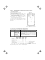
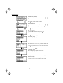
1.1 Acceptance Inspection
Unpack the package and check the following:
(1) The package contains a Multi-function Keypad and its
instruction manual (this book).
(2) There have been no problems during transportation. In
particular, no parts are damaged or have fallen out of place
nor are there any dents on the body.
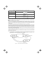
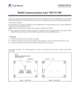
(3) The model name "TP-G1" is inscribed on the back of the
Multi-function Keypad as shown in Figure 1.1.
If you suspect the product is not working properly or if you have
any questions about your product, contact your Fuji Electric
representative.
Figure 1.1
Back of Multi-function Keypad
TP-G1
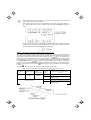
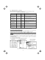
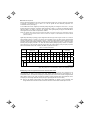
1.2 Inverters with which the Multi-function Keypad Interfaces
The Multi-function Keypad "TP-G1" interfaces with the following Fuji inverters:
Series
FRENIC-Eco
Type of inverter*
FRNF1S-
FRNF1H-
(Each has its meaning
as shown below,
represented by an
alphanumeric character.)
4
1
_
5
FRNF1E-
Remarks
The Multi-function Keypad is fully supported by inverters with a ROM
version of F1S10300 or later. (You can check the inverter’s ROM
version by entering menu #5, "
" in "Maintenance Information" in
Programming Mode.)
There are restrictions on the support for the Multi-function Keypad by
inverters with a ROM version of F1S10300 or earlier. For details,
consult your Fuji Electric representative.
* Type of inverter
For the details of the Inverter type identification, refer to the FRENIC-Eco Instruction Manual
(INR-SI47-0882-E), Chapter 1, Section 1.1 "Acceptance Inspection."
1-1
Chapter 2
INSTALLATION AND INTERCONNECTION
2.1 Accessories and Parts Required for Interconnection
To install your TP-G1 Multi-function Keypad on the enclosure’s panel instead of the inverter, you need the
following accessories and parts:
Accessories/Parts
Type or Specifications
Remarks
Remote Operation Extension Cable
(Note 1)
CB-5S, CB-3S, or CB-1S
You have a choice of three lengths: 5 m, 3
m, and 1 m.
Screws
(for mounting the Multi-function Keypad)
M3 x (Note 2)
Provide 2 screws (to be provided by the
customer) beforehand.
Note 1: Alternatively, you can use an off-the-shelf 10BASE-T/100BASE-TX LAN cable (straight type) that meets the
ANSI/TIA/EIA-568A Category 5 standard (maximum length: 20 m).
Recommended LAN Cable:
Manufacturer: Sanwa Supply, Co. Ltd.
Model:
KB-10T5-01K (for 1 m)
KB-STP-01K (for 1 m) (shielded cable, EMC-compliant)
Note 2: Use the screws of the length just right for the panel. (See Figure 2.7.)
2-1
2.2 Installing the TP-G1 Multi-function Keypad
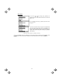
2.2.1
Three ways of installation/use
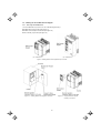
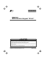
You can install and/or use your TP-G1 in one of the following three ways:
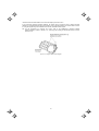
Install it directly on the inverter (see Figure 2.1).
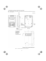
Install it on the front panel of enclosure (see Figure 2.2).
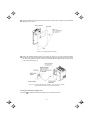
Use it remotely in your hand (see Figure 2.3).
(a)
FRN15F1S-2J
(b)
FRN37F1S-2J
Figure 2.1 Installing Multi-function Keypad Directly on Inverter
Figure 2.2
Installing Multi-function Keypad on Enclosure
2-2
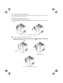
Figure 2.3
Using Multi-function Keypad
remotely in Your Hand
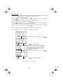
2.2.2
Installing the TP-G1 multi-function keypad
After completion of interconnection, follow the next steps to install the multi-function keypad in place. Be sure to
turn off the power of the inverter beforehand.
Installing the TP-G1 directly on the inverter
Remove the standard keypad mounted on the inverter.
Pull the standard keypad toward you while holding down the hook (as directed by the arrows in Figure 2.4
below).
Figure 2.4
Removing the Standard Keypad
Mount the TP-G1 Multi-function Keypad onto the inverter.
Put your TP-G1 Multi-function Keypad in the original slot while engaging its bottom latches with the holes
(as shown below), and push it onto the case of the inverter (arrow
) while holding it downward (against
the terminal block cover) (arrow ).
Figure 2.5
Mounting the Multi-function Keypad
2-3
<Protection from abnormal vibration: for inverters with capacity of 30 kW or less>
In an environment with large ambient vibrations, the inverter may be exposed to them, causing abnormal
vibrations on the Multi-function Keypad. If this happens, remove the terminal block cover and the front cover and
fix, using the keypad fixing screws attached to the inverter, the Multi-function Keypad.
For the procedures for removing the covers, refer to the FRENIC-Eco Instruction Manual
(INR-SI47-0882-E), Chapter 2, Section 2.3.1 " Removing and mounting the terminal block (TB) cover and
the front cover."
Figure 2.6
Fixing the Multi-function Keypad
2-4
Installing the multi-function keypad on the enclosure panel
Cut the panel out for a single square area and perforate two screw holes on the panel of the enclosure as
shown in Figure 2.7.
Figure 2.7
Dimensions of Square Cut-out and Screw Holes
2-5
Mount the Multi-function Keypad onto the enclosure with 2 screws as shown in Figure 2.8. (Recommended
tightening torque: 0.7 N•m)
Figure 2.8
Mounting Multi-function Keypad
Remove the standard keypad mounted on the inverter (see Figure 2.4) and, using a Remote Operation
Extension Cable or a LAN cable, interconnect the Multi-function Keypad and the Inverter (insert one end of
the cable into the RS485 port with RJ-45 connector on the Multi-function Keypad and the other end into that
on the inverter) (See Figure 2.9.).
Figure 2.9
Connecting Multi-function Keypad to the Inverter with Remote
Operation Extension Cable or an off-the-shelf LAN Cable
Using the multi-function keypad in hand
Follow step
of "Installing the multi-function keypad on the enclosure panel" above.
2-6
Chapter 3
OPERATION USING THE MULTI-FUNCTION KEYPAD
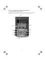
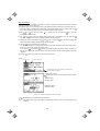
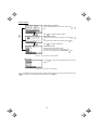
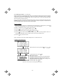
3.1 Key, LED, and LCD Monitors on the Keypad
The keypad allows you to start and stop the motor, view various data including maintenance information and
alarm information, set function codes, monitor I/O signal status, copy data, and calculate the load factor.
7-segment
LED monitor
LED indicator
indexes
LCD Monitor
RUN key
(forward)
Program key
LED indicator
RUN key
(reverse)
Shift key
STOP key
Reset key
UP key
Remote/Local
key
DOWN key
3-1
Function/Data key
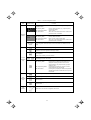
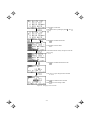
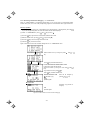
Table 3.1 Overview of Keypad Functions
Item
Monitor, LED
indicator or Key
Functions
Five-digit, 7-segment LED monitor which displays the following according to the
operation modes:
In Running Mode:
In Programming Mode:
In Alarm Mode:
LED/LCD
Monitor
Running status information (e.g., output frequency,
current, and voltage)
same as above
Alarm code, which identifies the cause of alarm if the
protective function is activated.
LCD monitor which displays the following according to the operation modes:
In Running Mode:
In Programming Mode:
In Alarm Mode:
LED indicator
indexes
Running status information
Menus, function codes and their data
Alarm code, which identifies the cause of alarm if the
protective function is activated.
In running mode, display the unit of the number displayed on the LED monitor and
the running status information shown on the LCD monitor. For details, see next
page.
Switches the operation modes of the inverter.
Shifts the cursor to the right when entering a number.
Pressing this key after removing the cause of an alarm will switch the inverter to
Running Mode.
Used to reset a setting or screen transition.
Keypad
Operation
Key
and
UP and DOWN keys. Used to select the setting items or change the function code
data displayed on the LED monitor.
Function/Data key. Switches the operation as follows:
In Running Mode:
In Programming Mode:
In Alarm Mode:
Pressing this key switches the information to be
displayed concerning the status of the inverter
(output frequency (Hz), output current (A), output
voltage (V), etc.).
Pressing this key displays the function code and
confirms the data you have entered.
Pressing this key displays the details of the problem
indicated by the alarm code that has come up on the
LED monitor.
Starts running the motor (forward rotation).
Starts running the motor (reverse rotation).
Run
Operation
Key
Stops the motor.
Pressing this toggle key for more than 1 second switches between Local and
Remote modes.
LED
Indicator
Lights while a run command is supplied to the inverter.
3-2
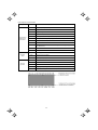
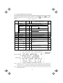
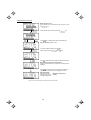
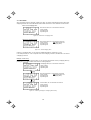
Items Displayed on LED Indicators
Type
Item
Hz
Unit of Number
Displayed on
LED Monitor
Operating
Status
Source of
Operation
Description (information, condition, status)
Output frequency, frequency command
A
Output current
V
Output voltage
%
Calculated torque, load factor, speed
r/min
Motor speed, set motor speed, load shaft speed, set load shaft speed
m/min
Line speed, set line speed (Not applicable to FRENIC-Eco)
kW
Input power, motor output
X10
Data greater than 99,999
min
Constant feeding rate time, constant feeding rate time setting (Not applicable
to FRENIC-Eco)
sec
Timer
PID
PID process value
FWD
Running (forward rotation)
REV
Running (reverse rotation)
STOP
No output frequency
REM
Remote mode
LOC
Local mode
COMM
JOG
HAND
Communication enabled (RS485 (standard, optional), field bus option)
Jogging mode (Not applicable to FRENIC-Eco)
Keypad effective (lights also in local mode)
3-3
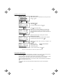
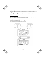
3.2 Overview of Operation Modes
FRENIC-Eco features the following three operation modes:
■ Running Mode:
This mode allows you to enter run/stop commands in regular operation. You can also
monitor the running status in real time.
■ Programming Mode: This mode allows you to set function code data and check a variety of information
relating to the inverter status and maintenance.
■ Alarm Mode:
If an alarm condition occurs, the inverter automatically enters the Alarm Mode. In this
mode, you can view the corresponding alarm code* and its related information on the
LED and LCD Monitors.
* Alarm code: Indicates the cause of the alarm condition that has triggered a protective function. For details,
refer to the FRENIC-Eco Instruction Manual (INR-SI47-0882-E), Chapter 8, Section 8.5 "Protection Features."
Figure 3.1 shows the status transition of the inverter between these three operation modes.
Figure 3.1
Status Transition between Operation Modes
3-4
3.3 Running Mode
When the inverter is turned on, it automatically enters Running Mode. In Running Mode, you can:
[ 1 ] Run or stop the motor;
[ 2 ] Set the frequency command and others;
[ 3 ] Monitor the running status (e.g., output frequency, output current)
3.3.1
Running/stopping the motor
By factory default, pressing the
key starts running the motor in the forward direction and pressing the
key is disabled. You can run or stop the motor using the keypad only
key decelerates the motor to stop. The
in Running mode and Programming mode.
To run the motor in reverse direction, or to run the motor in reversible mode, change the setting of function code
F02.
For details of function code F02, refer to the FRENIC-Eco Instruction Manual (INR-SI47-0882-E), Chapter
5.
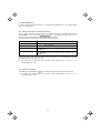
Figure 3.2
Rotational Direction of Motor
Note) The rotational direction of IEC-compliant motor is opposite to the one shown here.
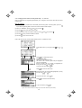
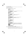
■ Display of running status (on LCD monitor)
(1) When function code E45 (LCD Monitor (optional)) is set to "0," the LCD Monitor displays the running status,
the rotational direction, and the operation guide.
(The indicators above the LCD Monitor indicate the unit of the number displayed on the LED Monitor; the
indicators underneath the LCD Monitor indicate the running status and the source of Run command.)
Figure 3.3
Display of Running Status
The running status and the rotational direction are displayed as shown in Table 3.2.
Table 3.2
Running Status and Rotational Direction
Status/Direction
Running status
Rotational direction
Description
RUN: The Run command is present, or the inverter is driving the motor.
STOP: The Run command is not present, or the inverter is in stopped state.
FWD: Forward
REV: Reverse
Blank: Stopped
3-5
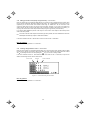
(2) When function code E45 (LCD Monitor (optional)) is set to "1," the LCD Monitor displays the output
frequency, output current, and calculated torque in a bar chart.
(The indicators above the LCD Monitor indicate the unit of the number displayed on the LED Monitor; the
indicators underneath the LCD Monitor indicate the running status and the source of Run command.)
The full scale (maximum value) for each parameter is as follows:
Output frequency: Maximum frequency
Output current:
200% of inverter’s rated current
Calculated torque: 200% of rated torque generated by motor
Figure 3.4
Bar Chart
■ Switching the operation mode between remote and local
The inverter can be operated either in remote mode or in local mode. In remote mode, which applies to normal
operation, the inverter is driven under the control of the data settings held in it, whereas in local mode, which
applies to maintenance operation, it is separated from the system and is driven manually under the control of
the keypad.
Remote mode:
The sources for setting run and frequency commands is determined by various
setting means switching signals such as function codes, switching of run command
1/2, and link priority function.
Local mode:
The sources for setting run and frequency commands is the keypad, regardless of the
settings specified by function codes. The keypad takes precedence over the setting
means specified by the run command 1/2 or the link priority function.
What follows shows the setting means of run command using the keypad in the local operation mode.
3-6
Table 3.3
Run Commands from the Keypad in the Local Operation Mode
Setting means of the run command
If function code F02 is set
to:
0: Keypad
You can run/stop the motor using the
/
/
key on the keypad.
You can run/stop the motor using the
/
key on the keypad.
1: External signal
2: Keypad (forward)
You can run the motor in forward direction only. (The
3: Keypad (reverse)
You can run/stop the motor using the
/
key has been disabled.)
key on the keypad.
You can run the motor in reverse direction only. (The
key has been disabled.)
The source for setting run and frequency commands can be switched between Remote and Local modes by the
key on the keypad. (This key is a toggle switch: Each time you press it for more than 1 second, the mode
switches from Romote to Local or vice versa.)
The mode can be switched also by an external digital input signal. To enable the switching you need to assign
(LOC) to one of the digital input terminals, which means that the commands from the keypad are given
precedence (one of function codes E01 to E05, E98, or E99 must be set to "35"). By factory default, (LOC) is
assigned to [X5].
You can confirm the current mode on the indicators (REM: Remote mode; LOC: Local mode).
When the mode is switched from Remote to Local, the frequency settings in the Remote mode are automatically
inherited. Further, if the inverter is in Running mode at the time of the switching from Remote to Local, the Run
command is automatically turned ON so that all the necessary data settings will be carried over. If, however,
there is a discrepancy between the settings on the keypad and those on the inverter itself (e.g., switching from
reverse rotation in the Remote mode to forward rotation in the Local mode using the keypad that is for forward
rotation only), the inverter automatically stops.
The paths of transition between Remote and Local modes depend on the current mode and the value (ON/OFF)
of (LOC), the signal giving precedence to the commands from the keypad, as shown in the state transition
diagram (Figure 3.5) given below.
For further details on how to set operation commands and frequencies in Remote and Local modes, refer
to the FRENIC-Eco User’s Manual (MEH456), Chapter 4 "BLOCK DIAGRAMS FOR CONTROL LOGIC"
(especially Section 4.3 “Drive Command Generator” block diagram).
Figure 3.5
Transition between Remote and Local Modes
3-7
3.3.2
Setting up the frequency and PID process commands
You can set up the desired frequency command and PID process command by using
keypad.
and
keys on the
You can also view and set up the frequency command as load shaft speed by setting function code E48.
■ Setting the frequency command
Using
and
keys (factory default)
(1) Set function code F01 to "0: Keypad operation." This cannot be done when the keypad is in Programming
and
keys, first move the keypad in
mode or Alarm mode. To enable frequency setting by using
Running mode.
(2) Pressing the
/
key causes the frequency command to be displayed on the LCD Monitor, with the
lowermost digit blinking.
Figure 3.6
Setting the Frequency Command in Local Mode
(3) If you need to change the frequency command, press the
/
key again. The new setting will be
automatically saved into the inverter’s internal non-volatile memory. It is kept there even while the inverter is
powered OFF, and will be used as the initial frequency next time the inverter is powered ON.
3-8
• The frequency setting can be saved either automatically as mentioned above or by pressing the
key. You can choose either way using function code E64.
• When you start specifying or changing the frequency command or any other parameter with the
/
key, the lowest digit on the display will blink and start changing. As you are holding the
key down, blinking will gradually move to the upper digit places and the upper digits will be
changeable.
• Pressing the
key moves the changeable digit place (blinking) and thus allows you to change
upper digits easily.
• By setting function code C30 to "0: Keypad operation (
/
key)" and selecting frequency
command 2 as the frequency setting method, you can also specify or change the frequency
/
key.
command in the same manner using the
• If you have set the function code F01 to "0: Keypad operation (
/
key)" but have selected a
frequency setting other than frequency 1 (i.e., frequency 2, set it via communications, or as a
/
key for setting the frequency command
multistep frequency), then you cannot use the
even if the keypad is in Running Mode. Pressing either of these keys will just display the currently
selected frequency command.
To have the frequency command displayed as the motor speed, load shaft speed, or speed (%), set function
code E48 (speed monitor selection) to 3, 4, or 7, respectively, as shown in Table 3.6 Monitored Items.
Table 3.4 Available Means of Setting
Symbol
Command sources
Symbol
Command sources
Command sources
PID-HAND
PID keypad
command
PID-P1
PID process
command 1
RS485 (standard)
PID-P2
PID process
command 2
RS485-2
RS485 (optional)
PID-U/D
PID UP/DOWN
process command
Terminal [V2]
BUS
Bus option
PID_LINK
PID
communication
process command
UP/DOWN control
LOADER
FRENIC loader
PID+MULTI
PID multistep
frequency
command
HAND
Keypad
MULTI
12
Terminal [12]
C1
Terminal [C1]
RS485-1
12 + C1
Terminal [12] +
Terminal [C1]
V2
U/D
Multistep
frequency
Symbol
3-9
■ Make setting under PID control
To enable PID control, you need to set function code J01 to 1 or 2.
Under the PID control, the items that can be set or checked with
and
keys are different from those
under regular frequency control, depending upon the current LED monitor setting. If the LED monitor is set to
and
keys; if it
the speed monitor, you may access manual speed commands (frequency command) with
is set to any other value, you may access the PID process command with those keys.
Refer to the FRENIC-Eco User's Manual (MEH456) for details on the PID control.
Setting the PID process command with
and
keys
(1) Set function code J02 to "0: Keypad operation."
(2) Set the LED monitor to something other than the speed monitor (E43 = 0) while the keypad is in Running
/
key while the keypad is in
Mode. You cannot modify the PID process command using the
/
Programming Mode or Alarm Mode. To enable the modification of the PID process command by the
key, first switch to Running Mode.
(3) Press the
/
key to have the PID process command displayed. The lowest digit will blink together
with the dot on the LED monitor.
Figure 3.7
PID Process Commands
(4) To change the PID process command, press the
/
key again. The PID process command you have
specified will be automatically saved into the inverter’s internal memory. It is kept there even if you
temporarily switch to another means of specifying the PID process command and then go back to the means
of specifying the PID process command via the keypad. Also, it is kept there even while the inverter is
powered OFF, and will be used as the initial PID process command next time the inverter is powered ON.
3-10
• Even if multistep frequency is selected as the PID process command ((SS4) = ON), you still can
set the process command using the keypad.
/
key displays, on
• When function code J02 is set to any value other than 0, pressing the
the 7-segment LED monitor, the PID command currently selected, while you cannot change the
setting.
• On the 7-segment LED monitor, the decimal point of the lowest digit is used to characterize what is
displayed. The decimal point of the lowest digit blinks when a PID process command is displayed;
the decimal point lights when a PID feedback value is displayed.
Setting up the frequency command with
and
keys under PID control
When function code F01 is set at "0: Keypad operation" and frequency command 1 (Frequency setting via
communications link: Disabled; Multistep frequency setting: Disabled; PID control: Disabled) is selected as the
/
key if you specify the LED
manual speed command, you can modify the frequency setting using the
monitor as the speed monitor while the keypad is in Running Mode. You cannot modify the frequency setting
/
key while the keypad is in Programming Mode or Alarm Mode. To enable the modification of
using the
/
key, first switch to Running Mode. These conditions are summarized
the frequency setting using the
in Table 3.5 and the figure below. Table 3.5 shows the combinations of the parameters, while the figure below
entered via the keypad is translated to the final frequency
illustrates how the manual speed command
command .
The setting and viewing procedures are the same as those for usual frequency setting.
Table 3.5
Frequency
command 1
(F01)
0
Speed (Frequency) Command Manually Set with
Frequency setting
via communications
link
Multistep
frequency setting
Disabled
Disabled
Other than the above
PID control
disabled
/
Key and Requirements
Display during
/
key operation
PID enabled
PID output (as final frequency command)
Disabled
Manual speed setting by keypad
(frequency setting)
PID enabled
PID output (as final frequency command)
Disabled
Manual speed command currently selected
(frequency setting)
3-11
3.3.3
LED monitor (Monitoring the running status)
The eleven items listed below can be monitored on the LED Monitor. Immediately after the inverter is turned ON,
key to switch
the monitor item specified by function code E43 is displayed. In Running Mode, press the
between monitor items. The item being monitored shifts as you press the
key in the sequence shown in
Table 3.6.
Table 3.6
Page to
be
selected
0
Monitored Item
Example
Speed Monitor
Items Monitored
Unit
Meaning of Displayed Value
Function code E48 specifies what to be displayed.
Function
code E43
0
Output frequency
5*00
Hz
Motor speed
1500
r/min
Load shaft speed
30*0
r/min Output frequency (Hz) x E50
(E48 = 4)
%
Output frequency
Maximum frequency
(E48 = 7)
Output of the inverter in current in rms
3
Input power to the inverter
9
8
5*0
Speed (%)
Frequency actually being output (Hz)
Output frequency ×
120
P01
× 100
(E48 = 0)
(E48 = 3)
8
Output current
1"34
A
9
Input Power
1*25
kW
10
Calculated torque
50
%
Motor output torque in % (Calculated value)
11
Output voltage
200
V
Output of the inverter in voltage in rms
4
12
Motor output
)85
kW
Motor output in kW
16
13
Load factor
50
%
Load rate of the motor in % with the rated output
being at 100%
15
PID process command/feedback value transformed
to that of physical value of the object to be
controlled.
10
14
PID process command
(Note 1)
1*0*
-
15
PID feedback value
(Note 1)
)0*
-
Refer to the function codes E40 and E41 for details.
12
16
PID output
(Note 1)
10**
%
PID output in % with the maximum output
frequency (F03) being at 100%
14
18
Analog input monitor
(Note 2)
8"00
-
Figure 3.8
Analog input to the inverter converted per E40 and
E41
17
Refer to the function codes E40 and E41 for details.
Selecting Items to be Monitored on LED Monitor
(Note 1) Displayed only if the inverter PID-controls the motor according to a PID process command specified by the
function code J01 (= 1 or 2). While the 7-segment LED monitor is displaying PID process command, PID
feedback value, or PID output value, the dot (decimal point) at the lowest digit on it is lit or blinking respectively.
(Note 2) Analog input monitoring becomes active only when enabled by any data of the function codes E61, E62 or E63
(Select terminal function).
3-12
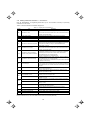
3.4 Programming Mode
Programming Mode provides you with the functions of setting and checking function code data, monitoring
maintenance information and checking input/output (I/O) signal status. The functions can be easily selected with
a menu-driven system. Table 3.7 lists menus available in the Programming Mode.
Table 3.7
Menu #
Menus Available in Programming Mode
Menu
Main functions
Refer to:
0
Quick Setup
Displays only basic function codes that are pre-selected.
3.4.2
1
Data Setting
Allows you to view and change the setting of the function code
you select. (Note)
3.4.1
2
Data Checking
Allows you to view and change a function code and its setting
(data) on the same screen. Also allows you to check the function
codes that have been changed from their factory defaults.
3.4.3
3
Drive Monitoring
Displays the running information required for maintenance or
test running.
3.4.4
4
I/O Checking
Displays external interface information.
3.4.5
5
Maintenance Information
Displays maintenance information including cumulative run time.
3.4.6
6
Alarm Information
Displays four latest alarm codes. Also allows you to view the
information on the running status at the time the alarm occurred.
3.4.7
7
Alarm cause
Displays the cause of the alarm.
8
Data Copying
Allows you to read or write function code data, as well as to
verify it.
9
Load Factor
Measurement
Allows you to measure the maximum output current, average
output current, and average braking power.
10
User Setting
Allows you to add or delete function codes covered by Quick
Setup.
11
Communication
Debugging
Allows you to confirm the data of the function codes for
communication (S, M, W, X, and Z codes).
3.4.8
(Note) The function codes for optional features (o code) are displayed only when they are installed. For details, refer to
their instruction manuals.
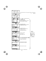
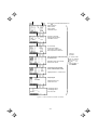
Figure 3.9 shows the transitions between menus in Programming mode.
Figure 3.9
Menu Transition in Programming Mode
When there has been no key operation for about 5 minutes, the inverter automatically goes back to the Running
mode and the back light goes OFF.
3-13
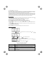
3.4.1
Setting function codes – "1. Data Setting"
Menu #1 "Data Setting" in Programming Mode allows you to set function codes according to your needs.
Table 3.8 lists the function codes available on the FRENIC-Eco.
Table 3.8
Function Code Group
Function Codes Available on FRENIC-Eco
Function Code
Function
Description
F code
(Fundamental functions)
F00 to F44
Fundamental
functions
Fundamental functions used in operation of the
motor
E code
(Extension terminal
functions)
E01 to E99
Terminal
functions
Functions concerning the selection of operation of
the control circuit terminals; Functions concerning
the display on the LED monitor
C code
(Control functions of
frequency)
C01 to C53
Control
functions
Functions associated with frequency settings
P code
(Motor parameters)
P01 to P99
Motor
parameters
Functions
for
setting
up
characteristics
parameters (such as capacity) of the motor
H code
(High performance
functions)
H03 to H98
High-level
functions
Highly added-value
sophisticated control
J code
(Application functions)
J01 to J22
Application
functions
Functions for applications such as PID Control
y code
(Link functions)
y01 to y99
Link
functions
Functions for controlling communications
o code
(Option functions)
o27 to o59
Optional
functions
Functions for optional features (Note)
functions;
Functions
for
(Note) The o code is displayed only when the corresponding optional feature is installed.
For details of the o code, refer to the Instruction Manual for the corresponding optional feature.
Function codes requiring simultaneous keying
To modify the data for function code F00 (data protection), H03 (data initialization), or H97 (clear alarm data),
simultaneous keying is needed, involving the
key + the
key.
key, or the
key + the
Modifying function code data during running; making the modification valid and saving the
modification
Some function codes can be modified while the inverter is running, whereas others cannot. Further, depending
on the function code, modifications may or may not become effective immediately. For details, refer to the
"Change when running" column in 5.1 "Function Code Tables" in Chapter 5 of the FRENIC-Eco Instruction
Manual (INR-SI47-0882-E).
For details of function codes, refer to 5.1 "Function Code Tables" in Chapter 5 of the FRENIC-Eco
Instruction Manual (INR-SI47-0882-E).
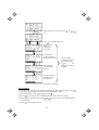
Figure 3.10 illustrates LCD screen transition for Menu item 1. DATA SET.
Menu screen
Function code list screen
Figure 3.10
Screen Transition for Data Setting Menu
3-14
Screen for modifying
function code data
Basic key operation
This section will give a description of the basic key operation, following the example of the function code data
changing procedure shown in Figure 3.11.
This example shows you how to change function code F03 data (maximum frequency) from 58.0 Hz to 58.1 Hz.
(1) When the inverter is powered ON, it automatically enters Running Mode. In Running Mode, press the
key to enter Programming Mode. The menu for function selection will be displayed.
(2) Using
and
keys, move the pointer Æ to "1. DATA SET" and then press the
display a list of function codes.
key, which will
(3) Use
and
keys to select the desired function code group (in this example, F03:), and press the
key, which will display the screen for changing the desired function code data.
(4) Change the function code data by using
and
keys. Pressing the
place to shift (cursor shifting) (The blinking digit can be changed).
(5) Press the
key causes the blinking digit
key to finalize the function code data.
The data will be saved in the memory inside the inverter. The display will return to the function code list, then
move to the next function code (in this example, F04).
If you press the
key before the
key, the change made to data of the function code is cancelled. The
data reverts to the previous value, the screen returns to the function code list, and the function code (F03)
reappears.
(6) Press the
key to return to the menu from the function code list.
Screen
Function code
Function code name
Operation guide: The function of each key is displayed by
automatic scrolling of this line.
Function code #, name
: Function code that has been changed from factory default
Data
Allowable range
Operation guide
Data before change
Data after change
Figure 3.11 Screen for Changing Function Code Data
Additional note on function code being selected
The function code being selected blinks, indicating the movement of the cursor (F03 blinks in this
example).
3-15
Press
/
key to enter Menu.
Select desired menu by shifting the pointer Æ with
/
key.
Press
key to finalize desired menu.
Press
key to return to Menu.
Select desired function code by moving the cursor with
key.
/
/
/
Figure 3.12
Press
key to finalize desired function code.
Press
/
key to change function code data.
Press
key to finalize function code data.
Press
key to cancel change of data.
Changing Function Code Data
3-16
3.4.2
Setting up function codes quickly using Quick setup – "0. QUICK SET"
Menu #0 "QUICK SET" in Programming Mode allows you to quickly set up a fundamental set of function codes
that you specify beforehand. Whereas at shipment from factory, only a predetermined set of function codes is
registered, you can add or delete some function codes using "10. USER SET." The set of function codes
covered by Quick Setup is held in the inverter (not the keypad). Therefore, if you mount your keypad onto
another inverter, the set of function codes held in the new inverter is subject to Quick Setup. If necessary, you
may copy the set of function codes subject to Quick Setup using the copy function ("8. DATA COPY").
If you perform data initialization (function code H03), the set of function codes subject to Quick Setup will be
reset to the factory default.
For the list of function codes subject to Quick Setup by factory default, refer to the FRENIC-Eco Instruction
Manual (INR-SI47-0882-E), Chapter 5 "FUNCTION CODES."
LCD screen transition from the "0. QUICK SET" menu is the same as with "1. DATA SET."
Basic key operation
Same as the basic key operation for "1. DATA SET."
3.4.3
Checking changed function codes –"2. DATA CHECK"
Menu #2 "DATA CHECK" in Programming Mode allows you to check function codes (together with their data)
that have been changed. The function codes whose data have been changed from factory default are marked
key, you can view or change its data.
with . By selecting a function code and pressing the
LCD screen transition from the "2. DATA CHECK" menu is the same as with "1. DATA SET," except for the
different screen listing function codes as shown below.
Function code
Changed
Figure 3.13
Function code data
LCD Screen Listing Function Codes
Basic key operation
Same as the basic key operation for "1. DATA SET."
3-17
3.4.4
Monitoring the running status –"3. OPR MNTR"
Menu #3 "OPR MNTR" allows you to check the running status during maintenance and test running. The display
items for "Drive Monitoring" are listed in Table 3.9.
Table 3.9
Symbol
Fot1
Drive Monitoring Display Items
Item
Output frequency
Fot2
Description
Output frequency
Reserved
Iout
Output current
Output current
Vout
Output voltage
Output voltage
TRQ
Calculated torque
Calculated output torque generated by motor
Fref
Frequency
command
Frequency command
Running direction
FWD: Forward, REV: Reverse, Blank: Stopped
Running status
IL: Current limitation, LU: Undervoltage, VL: Voltage limitation
SYN
Motor shaft speed
LOD
Load shaft speed
LIN
120
P01
Display value = (Output frequency Hz) × (Function code E50)
Reserved
SV
PID process
command
PV
PID feedback
value
MV
Display value = (Output frequency Hz) ×
PID output value
The PID process command and PID feedback value are displayed after
converting the value to a virtual physical value (e.g., temperature or pressure) of
the object to be controlled using the function code E40 and E41 data (PID display
coefficients A and B).
Display value = (PID process command/feedback value) × (Coefficient A - B) + B
PID output value, displayed in % (with Maximum frequency (F03) being 100%).
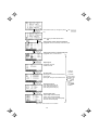
Figure 3.14 shows the LCD screen transition starting from the "OPR MNTR" menu.
3-18
Select desired menu by moving the pointer Æ with
key.
/
Press
/
key to finalize desired menu.
Output frequency
Reserved
Output current
Output voltage
/
Calculated torque
Frequency command
Running direction, status
Common operation:
To confirm data, call the
desired page using
/
key.
/
Motor shaft speed
Load shaft speed
Reserved
key to return
Press
to Menu.
/
PID process command
PID feedback value
PID output value
Figure 3.14
Menu Transition for "OPR MNTR"
Basic key operation
(1) When the inverter is powered ON, it automatically enters Running Mode. In Running Mode, press the
key to enter Programming Mode. The menu for function selection will be displayed.
(2) Select "3. OPR MNTR" by using
(3) Press the
and
keys (moving Æ).
key to display the screen for Operation Monitor (1 page out of a total of 4 pages).
(4) Select the page for the desired item by using
for the desired item.
(5) Press the
and
key to go back to the menu.
3-19
keys and confirm the running status information
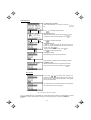
3.4.5
Checking I/O signal status – "4. I/O CHECK"
Menu #4 "I/O CHECK" in Programming mode allows you to check the digital and analog input/output signals
coming in/out of the inverter. This menu is used to check the running status during maintenance or test run.
Table 3.10 lists check items available.
Table 3.10 I/O Check Items
Item
Symbol
Input signals at terminal
block of control circuit
FWD, REV, X1 - X5
Shows the ON/OFF state of the input signals at the terminal
block of the control circuit.
(Highlighted when short-circuited; normal when open)
Description
Input signals coming via
Communication link
FWD, REV, X1 - X5,
XF, XR, RST
Input information for function code S06 (communication)
(Highlighted when 1; normal when 0)
Output signals
Y1 - Y3, Y5, 30ABC
Output signal information
I/O signals
(hexadecimal)
DI
Input signal at terminal block of control circuit (in hexadecimal)
DO
Output signal (in hexadecimal)
LNK
Input signal via communication link (hexadecimal)
Analog input signals
Analog output signals
12
Input voltage at terminal [12]
C1
Input current at terminal [C1]
V2
Input voltage at terminal [V2]
FMA
Output voltage at terminal [FMA]
FMA
Output current at terminal [[FMA]
FMP
Average output voltage at terminal [FMP]
FMP
Pulse rate at terminal [FMP]
Basic key operation
(1) When the inverter is powered ON, it automatically enters Running Mode. In Running Mode, press the
key to enter Programming Mode. The menu for function selection will be displayed.
(2) Select "4. I/O CHECK" by using
(3) Press the
and
keys (moving Æ).
key to display the screen for I/O Checking (1 page out of a total of 6 pages).
(4) Select the page for the desired item by using
desired item.
(5) Press the
and
keys and confirm the I/O check data for the
key to go back to the menu.
Figure 3.15 shows the LCD screen transition starting from the "4. I/O CHECK" menu.
3-20
/
Select desired menu by moving the pointer Æ with
key.
Press
/
key to finalize desired menu.
Input signal at control circuit terminal block
Highlighted when short-circuited; normal when open
/
/
/
/
/
Figure 3.15
Input signal coming via communication link
Highlighted when 1; normal when 0
Output signal
Highlighted when ON;
normal when OFF
I/O signal (hex)
Input signal at control circuit terminal block
Output signal
Input signal coming via communication link
Analog input signal
Input voltage at terminal [12]
Input current at terminal [C1]
Input voltage at terminal [V2]
Analog output signal
Output voltage at terminal [FMA]
Output current at terminal [FMA]
Average output voltage at terminal [FMP]
Pulse rate at terminal [FMP]
Menu Transition for "I/O CHECK"
3-21
Common
operation:
To confirm
data, call the
desired page
using
/
key.
Press
key to return
to Menu.
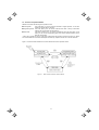
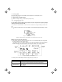
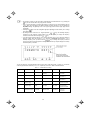
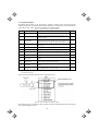
■ Hexadecimal expression
Each I/O terminal is assigned to one of the 16 binary bits (bit 0 through bit 15). The bit to which no I/O terminal
is assigned is considered to have a value of "0." The I/O signals are thus collectively expressed as a
hexadecimal number (0 through F).
In the FRENIC-Eco Series, digital input terminals [FWD] and [[REV] are assigned to bits 0 and 1, and [X1]
through [X5] to bits 2 through 6, respectively. Each bit assumes a value of "1" when the corresponding signal is
ON and a value of "0" when it is OFF(Note). For example, when signals [FWD] and [X1] are ON while all the
other signals are OFF, the status is expressed as "0005H."
(Note) The ON/OFF state of each signal at terminals [FWD], [REV], and X1 through [X5] is to be interpreted according to
the states of the source/sink switch as shown in Table 2.9 in Chapter 2 of the FRENIC-Eco Instruction Manual
(INR-SI47-0882-E).
Digital output terminals [Y1] through [Y3] are assigned to bits 0 through 2. Each is given a value of "1" when it is
short-circuited to [CMY], or a value of "0" when its circuit to [CMY] is open. The status of relay output terminal
[Y5A/C] is assigned to bit 4, which assumes a value of "1" when the contact between [Y5A] and [Y5C] is closed.
The status of relay output terminal [30A/B/C] is assigned to bit 8, which assumes a value of "1" when the contact
between [30A] and [30C] is closed or "0" when the contact between [30B] and [30C] is closed. For example,
when terminal [Y1] is ON, terminals [Y2] and [Y3]] are OFF, the contact between [Y5A] and [Y5C] is opened,
and the link between 30A and 30C is closed, the status is expressed as "0101H."
Table 3.11 Hexadecimal Notation
Data
Displayed
Bit
Highest digit
15
14
13
Input signal (RST)* (XR)* (XF)*
Example
(input)
Output signal
Binary
Lowest digit
12
11
10
9
8
7
6
5
4
3
-
-
-
-
-
-
[X5]
[X4]
[X3]
[X2]
2
1
0
[X1] [REV] [FWD]
-
-
-
-
-
-
-
[30A/B
/C]
-
-
-
[Y5A
/C]
-
[Y3]
[Y2]
[Y1]
0
0
0
0
0
0
0
0
0
0
0
0
0
1
0
1
0005H
Hex
-: unassigned
* (XF), (XR), (RST) are for communications. Refer to the subsection below.
Displaying control I/O signal terminals under communication control
During control via communication, input commands sent via RS485 communications can be displayed in two
ways depending on setting of the function code S06: "Display with ON/OFF of the LED segment" or "In
hexadecimal format." The content to be displayed is basically the same as that for the control I/O signal terminal
status display; however, (XF), (XR), and (RST) are added as inputs. Note that under communications control,
I/O display is in normal logic (ON when active) (using the original signals that are not inverted).
Refer to the RS485 Communication User's Manual (MEH448a) for details on input commands sent
through RS485 communications and the instruction manual of communication-related options as well.
3-22
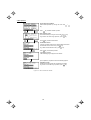
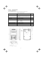
3.4.6
Reading maintenance information – "5. MAINTENANC"
Menu #5 "MAINTENANC" in Programming Mode allows you to view information necessary for performing
maintenance on the inverter.
Table 3.12 lists the maintenance information display items.
Table 3.12
Symbol
Display Items for Maintenance
Item
Description
Shows the cumulative run time during which the inverter was powered
ON.
TIME
Cumulative run time
EDC
DC link circuit voltage
Shows the DC link circuit voltage of the inverter’s main circuit.
TMPI
Max. temperature inside the inverter
Shows a maximum temperature inside the inerter every hour.
TMPF
Max. temperature of heat sink
Shows the maximum temperature of the heat sink every hour.
Imax
Max. effective current
Shows the maximum current in rms every hour.
CAP
Shows the current capacitance of the DC bus capacitor as % of the
capacitance at factory shipment. Refer to the FRENIC-Eco Instruction
Capacitance of the DC bus capacitor
Manual (INR-SI47-0882-E), Chapter 7 "MAINTENANCE AND
INSPECTION" for details.
MTIM
Cumulative motor run time
TCAP
Cumulative run time of electrolytic
capacitor on the printed circuit board
When the total time exceeds 65,535 hours, the counter will be reset to
0 and the count will start again.
Shows the cumulative run time of the motor.
When the total time exceeds 65,535 hours, the counter will be reset to
0 and the count will start again.
Shows the product of the cumulative time of voltage being applied to
the electrolytic capacitor on the printed circuit board and a coefficient
determined by the environmental condition. When the total time
exceeds 65,535 hours, the counting will stop.
As a guide, 61,000 hours is considered as life.
Shows the cumulative run time of the cooling fan. When the total time
exceeds 65,535 hours, the counting will stop.
TFAN
Cumulative run time of the cooling
fan
NST
Count of start-ups
Wh
Input watt-hour
Note 1)
Shows the input watt-hours of the inverter. Upon exceeding 1,000,000
kWh, the count goes back to 0.
PD
Input watt-hour data
Note 1)
Shows the input watt-hour data as input watt-hour (kWh) x function
code E51. (The range of display is 0.001 to 9,999. Values exceeding
9,999 are expressed as 9,999.)
Shows the total count of start-ups of the motor (count of times when
the run command for the inverter was turned ON). When the total time
exceeds 65,535 hours, the counter will be reset to 0 and the count will
start again.
Shows the cumulative count of RS485 communications card
(standard) errors since first power ON.
Count of RS485-1 errors
NRR1
RS485-1 error content
Note 2)
Shows the latest error that has occurred with RS485 communications
(standard) in a code.
Shows the cumulative count of RS485 communications card (option)
errors since first power ON.
Count of RS485-2 errors
NRR2
RS485-2 error content
As a guide, 61,000 hours is considered as life (This number varies with
the capacity of the inverter.)
Note 2)
Shows the latest error that has occurred with RS485 communications
(option) in a code.
Count of option errors
Shows the cumulative count of errors detected during optional
communication with option installed.
Option error code
Shows the latest error that has been detected during optional
communication in a code.
MAIN
ROM version of the inverter
Shows the ROM version of the inverter in 4 digits.
KP
ROM version of the keypad
Shows the ROM version of the keypad in 4 digits.
OP1
ROM version of the option
Shows the ROM version of the option in 4 digits.
NRO
Note 1) To reset the input watt-hour and input watt-hour data to 0, set function code E51 to "0.000."
Note 2) For details of errors, refer to the RS485 Communication User’s Manual (MEH448a).
3-23
Basic key operation
(1) When the inverter is powered ON, it automatically enters Running Mode. In Running Mode, press the
key to enter Programming Mode. The menu for function selection will be displayed.
(2) Select "5. MAINTENANC" by using
(3) Press the
and
(4) Select the page for the desired item by using
desired item.
(5) Press the
keys (moving Æ).
key to display the screen for Maintenance (1 page out of a total of 7 pages).
and
keys and confirm the Maintenance data for the
key to go back to the menu.
Figure 3.16 shows the LCD screen transition starting from the "5. MAINTENANC" menu.
3-24
Select desired menu by moving the pointer Æ with
key.
/
/
Press
key to finalize desired menu.
Cumulative run time
DC link circuit voltage
Max. temperature inside the inverter
Max. temperature of heat sink
/
Max. effective current
Capacitance of the DC bus capacitor
Cumulative motor run time
/
Cumulative run time of
electrolytic capacitor (reference)
Cumulative run time of
the cooling fan (reference)
Common
operation:
/
Number of start-ups
Input watt-hour
Input watt-hour data
Press
key to
return to Menu.
/
No. of errors & Error content for RS485-1
No. of errors & Error content for RS485-2
No. of errors & Error code
for Option communication
/
ROM version of the inverter
ROM version of the keypad
/
ROM version of the option
Figure 3.16
To confirm data,
call the desired
/
page using
key.
Menu Transition for "MAINTENANC"
3-25
3.4.7
Reading alarm information – "6. ALM INF"
Menu #6 "ALM INF" in Programming Mode allows you to view the information on the four most recent alarm
conditions that triggered protective functions (in alarm code and the number of occurrences). It also shows the
status of the inverter when the alarm condition occurred.
Table 3.13 lists the details of the alarm information.
Table 3.13 Alarm Information Displayed
Symbol
Item
Description
O/1
Most recent alarm
-1
2nd recent alarm
Alarm code and count of occurrences
-2
3rd recent alarm
Alarm code and count of occurrences
-3
4th recent alarm
Alarm code and count of occurrences
Fot1
Output frequency
Output frequency
Iout
Output current
Output current
Vout
Output voltage
Output voltage
TRQ
Calculated torque
Motor output torque
Fref
Frequency command
Frequency command
Running direction
FWD: Forward, REV: Reverse, Blank: Stopped
Running status
Alarm code and count of occurrences
IL: current limitation, LU: undervoltage, VL: voltage limitation
Shows the cumulative power-ON time of the inverter.
TIME
Cumulative run time
NST
Count of startups
Shows the cumulative count of times the motor has been started (the inverter
run command has been issued). When the total count exceeds 65,535, the
display will be reset to 0 and the count will start again.
EDC
DC link circuit voltage
Shows the DC link circuit voltage of the inverter's main circuit.
TMPI
Temperature inside the
inverter
Shows the temperature inside the inverter.
TMPF
Max. temperature of
heat sink
Shows the maximum temperature of the heat sink.
TRM
Input signal status at
terminal block of
control circuit
ON/OFF status of input signals of the terminals
[FWD], [REV], [X1] to [X5] (Highlighted when short-circuited; normal when
open)
LNK
Terminal input signal
status under
communication control
ON/OFF status of input signals for function code S06 (Communication).
[FWD], [REV], [X1] to [X5], (XF), (XR), (RST) (Highlighted when 1; normal
when o)
-
Output signal
3
Overlapping alarm 1
2
Overlapping alarm 1
SUB
Error sub-code
When the total time exceeds 65,535 hours, the display will be reset to 0 and the
count will start again.
Output signals to the terminals [Y1] to [Y3], [Y5], [30ABC]
Simultaneously occurring alarm codes (1)
("----" is displayed if no alarms have occurred.)
Simultaneously occurring alarm codes (2)
("----" is displayed if no alarms have occurred.)
Secondary error code for the alarm.
When the same alarm occurs a number of times in succession (reoccurring alarm), the alarm
information for the first occurrence is retained and the information for the subsequent occurrences is
discarded. Only the number of consecutive occurrences will be updated.
3-26
Basic key operation
(1) When the inverter is powered ON, it automatically enters Running Mode. In Running Mode, press the
key to enter Programming Mode. The menu for function selection will be displayed.
(2) Select "6. ALM INF" by using
and
keys (moving Æ).
(3) Press the
key to get the Alarm list screen, which displays information on the four most recent alarm
conditions (alarm code and the number of occurrences for each alarm condition).
(4) Select the alarm condition to be displayed, by using
and
keys.
(5) Press the
key to display the alarm code on the LED Monitor and the screen for the status data at the
time of the alarm (1 page out of a total of 7 pages) on the LCD Monitor.
(6) Select the page for the desired item by using
item.
(7) Press the
and
key to return to the alarm list. Press the
keys and confirm the status data for the desired
key again to return to the menu.
Figure 3.17 shows the LCD screen transition starting from the "6. ALM INF" menu.
/
Select desired menu by moving the pointer Æ with
key.
Press
/
key to finalize desired menu.
Cause & No. of occurrences of most recent alarm
Cause & No. of occurrences of 2nd most recent alarm
Cause & No. of occurrences of 3rd most recent alarm
Cause & No. of occurrences of 4th most recent alarm
key to return to Menu.
Press
/
Select desired alarm by moving the cursor with
key.
Press
key to finalize desired alarm info.
Figure 3.17 Menu Transition for "ALM INF"
3-27
/
Press
key to finalize desired alarm info.
Output frequency
Output current
Output voltage
Calculated torque
/
Frequency command
Running direction/status
Cumulative run time
/
No. of startups
DC link circuit voltage
Temperature inside inverter
Max. temperature of heat sink
Common
operation:
/
Input signal status at terminal block
of control circuit
Highlighted when short-circuited;
normal when opened
/
Terminal input signal status
under communication control
Highlighted when 1; normal when 0
/
Output signal
Highlighted when ON;
normal when OFF
/
Overlapping alarm 2
Overlapping alarm 1
Error sub-code
Figure 3.17
Menu Transition for "ALM INF" (continued)
3-28
To confirm data,
call the desired
/
page using
key.
key to
Press
return to Menu.
3.4.8
Viewing cause of alarm – "7. ALM CAUSE"
Menu #7 "ALM CAUSE" in Programming Mode allows you to view the information on the four most recent alarm
conditions that triggered protective functions (in alarm code and the number of occurrences). It also shows the
cause of each alarm.
Basic key operation
(1) When the inverter is powered ON, it automatically enters Running Mode. In Running Mode, press the
key to enter Programming Mode. The menu for function selection will be displayed.
(2) Select "7. ALM CAUSEF" by using
and
keys (moving Æ).
(3) Press the
key to get the Alarm list screen, which displays information on the four most recent alarm
conditions (alarm code and the number of occurrences for each alarm condition).
(4) Select the alarm condition to be displayed, by using
and
keys.
(5) Press the
key to display the alarm code on the LED Monitor and the screen for the cause of the alarm
(can be more than 1 page) on the LCD Monitor.
(6) Press
(7) Press the
and
keys to view the previous/next page.
key to return to the alarm list. Press the
key again to return to the menu.
Figure 3.18 shows the LCD screen transition starting from the "7. ALM CAUSE" menu.
3-29
/
Select desired menu by moving the pointer Æ with
key.
Press
/
key to finalize desired menu.
Cause & No. of occurrences of most recent alarm
Cause & No. of occurrences of 2nd most recent alarm
Cause & No. of occurrences of 3rd most recent alarm
Cause & No. of occurrences of 4th most recent alarm
key to return to Menu.
Press
/
Select desired alarm by moving the cursor with
key.
Press
key to finalize desired alarm cause page.
Alarm cause (1st page)
/
Press
key to return to alarm list screen.
Press
/
key to check all alarm causes.
nd
Alarm cause (2
page)
Figure 3.18 Menu Transition for "ALM CAUSE"
3-30
/
3.4.9
Data copying – "8. DATA COPY"
Menu #8 "Data Copying" in Programming Mode allows you to read function code data out of an inverter for
which function codes are already set up and then to write such function code data altogether into another
inverter, or to verify the function code data held in the keypad with the one in the inverter.
The keypad can hold three sets of function code data in three areas of its internal memory so that it can be used
with three different inverters. You can read the function code data of an inverter into one of these memory areas
or write the function code data held in one of these memory areas into the inverter you select. On the LCD
screen, each set of function code data or memory area is given a name such as DATA 1 and DATA 2.
Basic key operation
(1) When the inverter is powered ON, it automatically enters Running Mode. In Running Mode, press the
key to enter Programming Mode. The menu for function selection will be displayed.
(2) Select "8. DATA COPY" by using
(3) Press the
and
keys (moving Æ).
key to get the data copy index screen (list of data copy operations).
(4) Select the operation (read, write, verify, check), by using
(5) Press the
keypad.
and
keys (moving Æ).
key to finalize the choice of operation and then select the data set (or storage area) on the
(6) Press the
key to finalize the selection and perform the operation of your choice (for details, refer to the
LCD screen transition diagram below).
(7) Press the
key to return to the menu.
Figure 3.19 shows the LCD screen transition starting from the "8. DATA COPY" menu.
1) Selecting Copy Operation
/
Select desired menu by moving the pointer Æ with
key.
Press
/
key to finalize desired menu.
List of data copy operations
Select desired operation by moving the cursor with
key.
To return to Menu, press
/
key.
Figure 3.19 Menu Transition for "DATA COPY"
Table 3.14 List of DATA COPY Operations
Operation
Description
Read: Read data
Reads out function code data from the inverter and stores it into the internal memory of
the keypad.
Write: Write data
Writes the data held in the selected memory area of the keypad into the inverter.
Verify: Verify data
Verifies the data held in the keypad’s internal memory against the function code data in
the inverter.
Check: Check data
Checks the model information (format) and function code data held in the three memory
areas of the keypad.
3-31
2) Read Operation
List of data copy operations
Select desired operation by moving the cursor with
key.
Press
key to finalize desired operation.
Data selection screen
/
Select desired data by moving the cursor with
To go back to List of data copy operations, press
Press
/
key.
key.
key to finalize desired data.
Confirmation screen
If "Read" is actually performed, the data read out from the
inverter will overwrite the data held in this memory area in the
key.
keypad. If OK, press
To go back to Data selection screen, press
key.
Press
key to start Read operation.
"In progress" screen
A bar indicating progress appears in the bottom.
Upon completion, Completion screen automatically appears.
Completion screen
Indicates that Read operation has completed successfully.
key.
To go back to List of data copy operations, press
Error screens
If you press
/
key during Read operation, the
operation under way will be aborted, and this Error screen will
appear.(Note) Once aborted, all the data held in the keypad’s
memory would be deleted.
If a communication error is detected between the keypad and
the inverter, this Error screen will appear.
Figure 3.20
Menu Transition for "READ"
If an ERROR screen or an ERROR Ver. Screen appears during operation, press the
key to reset the
error condition. When Reset is complete, the screen will go back to List of data copy operations.
3-32
3) Write operation
List of data copy operations
Select desired operation by moving the cursor with
key.
Press
key to finalize desired operation.
Data selection screen
/
Select desired data by moving the cursor with
To go back to List of data copy operations, press
Press
/
key.
key.
key to finalize desired data.
Confirmation screen
If "Write" is actually performed, the selected data will overwrite
key.
the data held in the inverter. If OK, press
key.
To go back to Data selection screen, press
Press
key to start Write operation.
"In progress" screen
A bar indicating progress appears in the bottom.
Upon completion, Completion screen automatically appears.
Completion screen
Indicates that Write operation has completed successfully.
key.
To go back to List of data copy operations, press
Figure 3.21 Menu Transition for "WRITE"
3-33
Error screens
If you press
/
key during Write operation, the
operation under way will be aborted, and this Error screen will
appear.(Note) Updating of the function code data in the inverter
is incomplete, with some of it remaining old. Do not run the
inverter in this state. Before running the inverter, redo the
writing or perform initialization.
For safety considerations, the following situations are treated
as an error:
• No valid data is found in the keypad’s memory. (No Read
operation has been performed since factory shipment; or, a
Read operation has been cancelled or aborted.)
• The data held in the keypad’s memory has an error.
• There is a mismatch in inverter’s model number.
• A Write operation has been performed while the inverter is
running.
• The inverter is data-protected.
• The Write enable for keypad command (WE-KP) is OFF.
The function code data held in the keypad is incompatible with
that in the inverter. (Either data may be non-standard; or a
version upgrade performed in the past may have made the
keypad or the inverter incompatible. Contact your Fuji Electric
representative.)
Figure 3.21
Menu Transition for "WRITE" (continued)
If an ERROR screen or an ERROR Ver. Screen appears during operation, press the
key to reset
the error condition. When Reset is complete, the screen will go back to List of data copy operations.
3-34
4) Verify operation
List of data copy operations
Select desired operation by moving the cursor with
key.
Press
/
key to finalize desired operation.
Data selection screen
/
Select data to be verified by moving the cursor with
key.
key.
To go back to List of data copy operations, press
Press
key to finalize desired data.
Confirmation screen
key.
If OK, press
To go back to Data selection screen, press
Press
key.
key to start Verify operation.
"In progress" screen
A bar indicating progress appears in the bottom.
When a mismatch is found, the Verify operation is halted, with
the function code and its data displayed on the LCD Monitor.
To resume the Verify operation from the next function code,
key again.
press
To resume Verify, press
key.
"In progress" screen
A bar indicating progress appears in the bottom.
Upon completion, Completion screen automatically appears.
Completion screen
Indicates that Verify operation has completed successfully.
key.
To go back to List of data copy operations, press
Figure 3.22 Menu Transition for "VERIFY"
3-35
Error screens
If you press
/
key during Verify operation, the
operation under way will be aborted, and this Error screen will
appear. (Note)
If the keypad does not have any valid data, this Error screen
will appear. (Note)
The function code data held in the keypad is incompatible with
that in the inverter. (Either data may be non-standard; or a
version upgrade performed in the past may have made the
keypad or the inverter incompatible. Contact your Fuji Electric
representative.)
Figure 3.22 Menu Transition for "VERIFY" (continued)
If an ERROR screen or an ERROR Ver. Screen appears during operation, press the
key to reset
the error factor. When Reset is complete, the screen will go back to List of data copy operations.
3-36
5) Check operation
List of data copy operations
Select desired operation by moving the cursor with
key.
Press
/
key to finalize desired operation.
Data selection screen
/
Select data to be checked by moving the cursor with
key.
key.
To go back to List of data copy operations, press
Press
key to finalize desired data.
"Check data" screen
Displays function codes and their data.
/
key.
To check other function codes, press
key.
To go back to List of data copy operations, press
Figure 3.23
Menu Transition for "DATA CHECK"
Error screen
If no valid data is found in the keypad, this Error screen will
appear. (Note)
Figure 3.24 Error Screen for "DATA COPY"
If an ERROR screen appears during operation, press the
key to reset the error factor. When Reset
is complete, the screen will go back to List of data copy operations.
3-37
3.4.10 Measuring load factor – "9. LOAD FCTR"
Menu #9 "LOAD FCTR" in Programming Mode allows you to measure the maximum output current, the average
output current, and the average braking power. There are two modes of measurement: "hours," in which the
measurement takes place for a specified length of time, and "start to stop," in which the measurement takes
place from the start of running to the stop.
If the "start to stop" mode is entered while the inverter is running, the measurement takes place until it
is stopped. If the "start to stop" mode is entered while the inverter is stopped, the measurement will
take place from the next start of running until it is stopped.
Basic key operation
(1) When the inverter is powered ON, it automatically enters Running Mode. In Running Mode, press the
key to enter Programming Mode. The menu for function selection will be displayed.
(2) Select "9. LOAD FCTR" by using
(3) Press the
and
keys (moving Æ).
key to get the measurement mode selection screen.
(4) Select the measurement mode, by using
and
keys (moving Æ).
(5) Press the
key to start the measurement. For "start to stop" mode, you will be prompted to enter a run
command via a confirmation screen. For details, refer to the LCD screen transition chart.
(6) Press the
key to return to the menu.
Figure 3.25 shows the LCD screen transition starting from the "9. LOAD FCTR" menu.
1) Selecting measurement mode
/
Select desired menu by moving the pointer Æ with
To finalize desired menu, press
/
key.
key.
Mode selection screen
HOURS SET: Measurement takes place for specified duration
STARTÎSTOP: Measurement takes place from start to stop.
EXECUTING: Measurement is taking place according to the
specified duration set in HOURS SET.
key.
To return to Menu, press
Figure 3.25
Menu Transition for Selecting Measurement Mode
3-38
2) Selecting "hours set" mode
Mode selection screen
Select desired mode of measurement by moving the cursor
/
key.
with
/
Select desired mode of measurement with
Press
/
key.
key to finalize desired mode of measurement.
Set time duration (Default: 1 hour)
To go back to Mode selection, press
/
Set the duration by using
Press
,
, and
key.
keys.
key to finalize the duration and start measurement.
Measurement in progress (remaining time)
While the measurement is in progress, the remaining time is
displayed.
When
key is pressed or the measurement duration has
elapsed, the measurement stops, displaying the results.
Specified duration
[Display of measurement
Max. output current
results]
Average output current
Average braking power
Figure 3.26
Menu Transition for "LOAD FCTR" (hours set mode)
3-39
3) Selecting "start to stop" mode
Mode selection screen
Select desired mode of measurement by moving the cursor
/
key.
with
Confirmation screen
If OK, press
key.
To go back to Mode selection, press
Press
key.
key to signal "Ready."
Waiting for Run command (Standby for measurement)
Upon receiving Run command, the measurement will start.
If a Run command has already been received, this screen will
be skipped.
Run com. ON
Measurement will start upon receiving Run command.
Measurement in progress
The measurement will continue until the inverter is stopped.
key.
To discontinue the measurement, press
Stopped /
Measurement will stop when the inverter is stopped or you
key.
press
Duration
Max. output current
Average output current
Average braking power
[Display of measurement
results]
To return to Mode selection, press
Figure 3.27
key.
Menu Transition for "LOAD FCTR" (start to stop mode)
4) Going back to Running mode
While the measurement of the load factor is in progress, you can go back to the running mode by
pressing the
key (or, to the Mode selection screen by pressing the
key).
In these cases, the measurement of the load factor will continue. You can go back to "9. LOAD
FCTR" and confirm, on the Mode selection screen, that the measurement is in progress.
After the measurement has ended, you can view the results of the measurement by pressing the
key on the Mode selection screen.
The results of the measurement will be deleted when the inverter is powered OFF.
3-40
3.4.11 Changing function codes covered by Quick setup – "10. USER SET"
Menu #10 "USER SET" in Programming Mode allows you to change the set of function codes that are covered
by Quick setup.
Basic key operation
(1) When the inverter is powered ON, it automatically enters Running Mode. In Running Mode, press the
key to enter Programming Mode. The menu for function selection will be displayed.
(2) Select "10. USER SET" by using
(3) Press the
and
keys (moving Æ).
key to get the list of function codes.
(4) Select the function codes to be added or deleted, by using
(5) Press the
key to perform the addition or deletion.
(6) Press the
key to return to the menu.
and
keys (moving Æ).
Figure 3.28 shows the LCD screen transition starting from the "10. USER SET" menu.
/
Select desired menu by moving the pointer Æ with
key.
Press
/
key to finalize desired menu.
List of function codes
Lists function codes with their names.
The function codes covered by Quick setup are highlighted
(names are highlighted).
Select the function code to be added (not highlighted) by
and
keys.
moving the cursor with
To go back to the menu, press
key.
Press
key to add it to Quick setup.
Select the function code to be deleted (highlighted) by moving
and
keys.
the cursor with
To go back to the menu, press
Press
key to delete it from Quick setup.
To go back to Menu, press
Figure 3.28
key.
key.
Menu Transition for Changing Function Codes Covered by Quick Setup
3-41
3.4.12 Performing communication debugging – "11. COMM DEBUG"
Menu #11 "COMM DEBUG" in Programming Mode allows you to view the data of communication-related
function codes (S, M, W, X, and Z codes) to help debug programs for communication with an upper-level device.
Basic key operation
(1) When the inverter is powered ON, it automatically enters Running Mode. In Running Mode, press the
key to enter Programming Mode. The menu for function selection will be displayed.
(2) Select "11. COMM DEBUG" by using
(3) Press the
and
keys (moving Æ).
key to get the list of communication-related function codes.
(4) Select the function code, by using
and
keys (moving Æ).
(5) Press the
key to check or change the function code.
(6) Press the
key to return to the menu.
Figure 3.29 shows the LCD screen transition starting from the "11. COMM DEBUG" menu.
/
Select desired menu by moving the pointer Æ with
key.
Press
key to finalize desired menu.
List of communication-related function codes
Lists function codes with their names.
Select the function by moving the cursor with
keys.
To go back to the menu, press
key.
Press
S Code
/
and
key to finalize desired menu.
# & name of function code
( : Data exists (≠ 0))
Data
Range
Operation guide
Data can be changed by
/
key.
pressing
M, W, X, Z Code
Reference only (Cannot be
changed)
Data
Operation guide
Figure 3.29
Menu Transition for Communication Debugging
3-42
3.5 Alarm Mode
When a protective function is triggered, resulting in an alarm, the inverter automatically enters the alarm mode,
displaying the alarm code on the LED Monitor and the details of the alarm on the LCD Monitor as shown below.
If there is no overlapping alarm
Most recent cause; No. of consecutive occurrences
Cause of alarm
Operation guide
Operation guide
Figure 3.30 Without Non-overlapping Alarm
If there is an overlapping alarm
Most recent cause; No. of consecutive occurrences
( is added if there is an
Cause of alarm
overlapping alarm.)
Operation guide
Operation guide
Figure 3.31 With Overlapping Alarm
If there is an overlapping alarm, you can view more detailed information by pressing the
key.
In the examples below, "2 = Er6" corresponds to the first overlapping occurrence, and "3 = Er6" to the second
overlapping occurrence.
Display of alarm history
In addition to the most recent (current) alarm, you can view three recent alarms and any overlapping alarms by
pressing the
/
key while the most recent one is being displayed.
Overlapping alarm; No. of consecutive occurrences
Cause of alarm
Operation guide
Operation guide
Most recent alarm; No. of consecutive occurrences
( is added if there is an
Cause of alarm
overlapping alarm.)
Operation guide
Operation guide
Previous alarm; No. of consecutive occurrences
Cause of alarm
Operation guide
Operation guide
Figure 3.32
Switching of Display of Overlapping Alarm History
3-43
Display of running status information at the time of alarm
By pressing the
key while an alarm code is displayed, you can view the output frequency, output current,
and other data concerning the running status. The data you can view is the same as with "6. ALM INF." Use
and
keys for scrolling pages within the menu.
Pressing the
key or the
display of the alarm code.
key while the running status information is displayed will take you back to the
Transition to Programming mode
key while alarm information is displayed, you can switch to the Programming mode, in
By pressing the
which you can use a variety of features such as changing function code data.
Resetting alarm; transition to Running mode
When you remove the cause of the alarm and press the
inverter will go back to the Running mode.
key, the alarm condition will be reset, and the
Figure 3.33 summarizes the menu transition between these modes.
Figure 3.33
Menu Transition in/from Alarm Mode
3-44
3.6 Other Precautions
For using a multi-function keypad note that your key operation will be differed from ones on a standard keypad
(TP-E1) for following points.
3.6.1
Function code setting for F02 (Run and operation)
/
key controls to run/stop the motor on the standard keypad (TP-E1) while the rotation command
The
/
/
key on the multi-function keypad controls to run
input is required. On the contrary, the
forward/reverse the motor without inputting any rotation command or stop it.
The function code F02 specifies the run command source to drive the motor.
F02 data
Run command source
0: Keypad
Pressing the
1: Digital input
The terminal command (FWD) or (REV) runs/stops the motor.
2: Keypad (Forward)
/
The
reverse.
key runs the motor forward or stops it, but does not run it
3: Keypad (Reverse)
/
The
forward.
key runs the motor reverse or stops it, but does not run it
/
/
key runs/stops the motor.
If you select Local by the Remote/Local switching command, operation of the run command from the keypad will
be changed by setting of the function code F02.
3.6.2
For details, refer to “■ Switching the operation mode between remote and local” in “3.3.1
Running/stopping the motor.”
Remote/local operation
The multi-function keypad features the
key to switch the operation between remote and local modes.
For details, refer to “■ Switching the operation mode between remote and local” in “3.3.1
Running/stopping the motor.”
3-45
3.6.3
Tuning motor parameters
The LCD monitor of multi-function keypad shows the lead-through screen for tuning of motor parameters. To
tune motor parameters follow screens below.
Entering into tuning motor parameters
Set data 1 or 2 into the function code P04 and press the
/
key.
Press
key to select the data either 1 or 2 being set
/
to the function code P04.
Press
key to select the tuning mode.
Waiting for a run command.
Turn on the
run command.
Give the specific run command, Run forward or Run
reverse. (Note 1)
Tuning the motor parameters. (Note 2)
End of tuning
Turn off the
run command.
Upon turning off the run command (while the run
command given by the keypad or the link operation is
automatically turned off) the lead-through ends the
tuning process, and moves to the next function code
P06.
(Note 1) The factory default setting is “Run forward” by using the
in “Run reverse”, change data of the function code F02.
key on the keypad. To tune the motor parameters
(Note 2) • Time needed for tuning while the motor is stopped (P04 = 1) will be less than 40 seconds.
• In tuning while the motor is running (P04 = 2), the inverter accelerates the motor up to around 50% of the
base frequency, starts tuning of motor parameters, and decelerates to stop the motor after the end of tuning.
Estimated time needed for tuning in this case will be (acceleration time + 10 + deceleration time) seconds.
3-46
Chapter 4
SPECIFICATIONS
4.1 General Specifications
Table 4.1 summarizes the general specifications of the Multi-function Keypad "TP-G1."
Table 4.1 General Specifications
Item
Specifications
Enclosure
Front side: IP40; Rear side: IP20
Environment
Indoor only.
Remarks
Shall be free from corrosive gases, flammable gases, dust, and
direct sunlight.
Ambient temperature (during operation)
-10 to +50°C
Ambient humidity
5 to 95% RH (no condensation)
Altitude
1000 m or below
Vibration
3 mm (max.)
9.8 m/s2
2
2 m/s
1 m/s2
Ambient temperature (during storage)
-25 to +65°C
Ambient humidity (during storage)
5 to 95% RH (no condensation)
External dimensions
See the figure below.
Mass
129 g
: 2 - 9 Hz
: 9 - 20 Hz
: 20 - 55 Hz
: 55 - 200 Hz
External dimensions
(Unit: mm)
4-1
4.2 Communication Specifications
Tables 4.2 and 4.3 summarize the communication specifications.
Table 4.2 Hardware Specifications
Item
Specifications
No. of inverters
connected
One inverter for one Multi-function Keypad
Connection cable
Shall meet the US ANSI/TIA/EIA-568A
Category 5 standard
(10BASE-T/100BASE-TX, straight).
Maximum
communication distance
20 m
Connector
RJ-45 connector
Remarks
A Remote Operation Extension Cable
is available as an option (CB-5S,
CB-3S, or CB-1S, depending on the
distance).
See Table 4.3.
Table 4.3 RJ-45 Connector Pin Assignment
Pin #
Signal
name
1, 8
Vcc
Description
Remarks
DC power source for Multi-function
Keypad (5 V)
2, 7
GND
Signal ground
3, 6
NC
Unassigned (reserved)
4
DX -
RS485 communication data ( - )
5
DX +
RS485 communication data ( + )
SW3 for the terminating resistor on the control circuit board in the inverter must be set to OFF (open).
4.3 Transmission Specifications
Table 4.4 summarizes the transmission specifications.
Table 4.4 Transmission Specifications
Item
Specifications
Area code
No need to specify.
Communication protocol
Modbus-RTU
Synchronization system
Start-stop
Communication system
Half-duplex
Communication speed
(Baud rate)
19200 bps
Parity
Even parity
Stop bit length
1 bit
Error checking
CRC-16
Remarks
There is no need to specify function
codes y01 through y10 for RS485
communication, which will be ignored
anyway.
4-2
MEMO
Multi-function Keypad "TP-G1"
Instruction Manual
First Edition, September 2004
Fuji Electric FA Components & Systems Co., Ltd.
The purpose of this manual is to provide accurate information in the handling, setting up and operating of
Multi-function Keypad "TP-G1" for the FRENIC-Eco series of inverters. Please feel free to send your comments
regarding any errors or omissions you may have found, or any suggestions you may have for generally improving
the manual.
In no event will Fuji Electric FA Components & Systems Co., Ltd. be liable for any direct or indirect damages
resulting from the application of the information in this manual.
Fuji Electric FA Components & Systems Co., Ltd.
2004-9 (I04/I04) 3CM