1
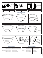
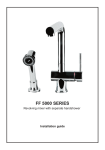
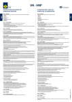
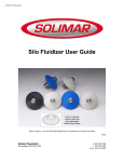
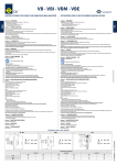
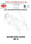
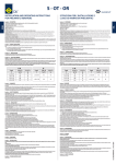
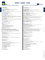
U025 - U060 - I100 INSTRUCTIONS FOR USING THE AIR FLUIDIZERS ISTRUZIONI PER L’USO DEI FLUIDIFICATORI Section 0 – DESCRIPTION Sezione 0 – DESCRIZIONE Section 1 – GENERAL REGULATIONS Sezione 1 – NORME GENERALI Symbol: ! It indicates situations of serious danger which, if ignored, can seriously put to a risk the health and safety of persons. Simbologia: ! Indica situazioni di grave pericolo che, se trascurate, possono mettere seriamente a rischio la salute e la sicurezza delle persone. On receiving product please: - Make sure that the packing is not damaged to such an extent as to have damaged the product. - Make sure that there is no external damage to the product. - Make sure that the supply corresponds to the order specifications; non compliance and/or external damage, if any, must be reported immediately in detail to the forwarding agent and the manufacturer and/or dealer. Section 1.1 – IDENTIFICATION Product identification codes are shown on the label of the box. This data must always be stated when ordering spare parts or asking for assistance. Section 1.2 – INTENDED USE Fluidizers U025 - U060 - I100 types can be used only to fluidize powder in a hopper or silo. U025-U060 can't be assembled on stainless steel hopper or silo. For correct working of the equipment it is necessary to abide by the instructions given in the Manual which must obviously be consulted before starting work. Using the equipment for purposes other than those described in this Manual will not only be considered as forbidden and improper, but will also free the manufacturer of all direct and/or indirect responsibility. Section 2 – GUARANTEE The Manufacturer provides a 24 (twenty-four)-months guarantee on all the products valid from the date of purchase (mentioned on the shipping document). The guarantee excludes all parts subject to wear. The guarantee becomes invalid, and together with it all direct and indirect responsibility, if the product has been tampered with or used improperly, and if the spare parts used are not genuine. The goods returned for repair within the guarantee period are CARRIAGE PAID. Section 3 – SAFETY STANDARDS SAFETY INDICATIONS ! Leggere attentamente queste istruzioni prima di utilizzare il prodotto, e custodire questo manuale per futuri riferimenti. Al ricevimento del prodotto controllare che: - L’imballo non risulti deteriorato al punto di aver danneggiato il prodotto. - Non vi siano danni esterni al prodotto. - La fornitura corrisponda alle specifiche dell’ordine; eventuali non conformità e/o danni esterni riscontrati dovranno essere segnalati immediatamente in modo dettagliato sia allo spedizioniere che alla casa produttrice e/o rivenditore. Sezione 1.1 – IDENTIFICAZIONE I codici di identificazione del prodotto sono riportati sugli appositi adesivi sulle confezioni. Questi dati devono essere sempre citati per eventuali richieste di parti di ricambio o per interventi di assistenza. Sezione 1.2 – DESTINAZIONE D’USO I fuidificatori U025 - U060 - I100 devono essere usati per la fluidificazione di sili e tramogge. U025-U060 non possono essere utilizzati su sili o tramogge in inox. Per un corretto funzionamento del prodotto è necessario attenersi alle istruzioni indicate sul manuale che naturalmente dovrà essere consultato prima dell'installazione sull'impianto. L’utilizzo dello stesso per impieghi diversi da quelli previsti e non conformi a quanto descritto in questo opuscolo, oltre ad essere considerato improprio e vietato, scarica la ditta costruttrice da qualsiasi responsabilità diretta e /o indiretta. Sezione 2 – GARANZIA Il costruttore garantisce i propri prodotti 24 (ventiquattro) mesi dalla data di acquisto (fa fede il documento di trasporto della merce). La garanzia esclude tutte le parti soggette ad usura. La garanzia decade, e con essa ogni responsabilità diretta o indiretta, qualora il prodotto sia stato manomesso o utilizzato in modo improprio, siano state fatte riparazioni o modifiche da personale non autorizzato, siano stati utilizzati ricambi non originali. I materiali resi per riparazione in garanzia vanno resi in PORTO FRANCO. Sezione 3 – NORME DI SICUREZZA INDICAZIONI DI SICUREZZA Rights reserved to modify technical specifications Please read instruction manual ! Leggere il manuale dell’operatore OPERATOR SAFETY •Wear appropriate P.P.E. during the installation. •If the Manual is lost, contact OLI for a copy or download it from our website www.olivibra.com SICUREZZA DELL’OPERATORE FUNCTIONAL SAFETY OF THE VIBRATING BIN AREATOR L’aria compressa che deve alimentare le varie utenze ha bisogno di particolari caratteristiche: •Pulita: esente da scorie che potrebbero danneggiare le elettrovalvole presenti sull’attuatore pneumatico. •Deumidificata: è opportuno prevedere l’utilizzo di un separatore di condensa. •Non lubrificata. Purezza dell’aria secondo ISO8573-1:2010 classe 5.4.1 The compressed air supplied to the various utilities must have certain special features: •Clean: free of scale which could damage the solenoid valves present on the pneumatic actuator. •Dehumidified: use of a condensate trap is advisable. •Unlubricated Air supply quality following ISO8573-1:2010 class 5.4.1 Max working pressure: •U025 0.2bar(2.9 psi), U060 1bar(14 psi), I100 0.2bar(2.9 psi). Noise level: The measured equivalent continuous noise pressure of the equipment NEVER exceeds 100 dB(A)* * Measurements made in normal operating conditions in accordance with UNI EN ISO 11202, with simulated load. IN ADDITION TO THE ABOVE, COMPLY WITH THE STANDARDS IN FORCE IN THE COUNTRY WHERE THE MACHINE IS USED. Section 4 – INSTALLATION AND USE OF THE FLUIDISATION NOZZLES AND AERATION PADS U025 A) Make a hole of approx. 36mm / 1.42 In and deburr it inside and outside. B) Area of installation ūū Clean the area around the hole. ūū Weld the metal ring (1) to the silo/hopper wall. Before to proceed to other installation steps make sure that the surrounding area have reached enviromental temperature. C) Screw the U025(2) on the metal ring(1). D) Mount 1/2" GAS air nipple (4-not included) and pipeline U060 A) Make a hole of approx. 62mm / 2.44 In. and deburr it inside and outside. B) Area of installation ūū Clean the area around the hole. ūū Weld the metal ring (1) to the silo/hopper wall. Before to proceed to other installation steps make sure that the surrounding area have reached enviromental temperature. C) Screw the U060(2) on the metal ring(1). D) Mount 3/8" GAS air nipple (4) and pipeline. I100 A) Make a hole Ø14mm / 0.55 In in the silo/hopper wall. B) Insert I100(1) from internal silo wall. C) Mount rubber washer(2). D) Mount washer (3) - UNI6592-TE-14-200HV E) Tighten fixing screw 1/4"GAS (4). F) Mount 1/4" GAS male air nipple (5-not included) and pipeline. Use pipelines that have a flow rate adequate to the number of the fluidizer used. The air compressor system must be placed at a distance from the first level of fluidizer not higher than 10mt(long distance may cause pressure drop) Equipment must be installed as idicated: compressor pressure regolator electropneumatic valve for automatic operation fluidizer. Failure to observe the instructions can cause product failure. •Indossare i D.P.I idonei durante l'installazione dei fluidificatori. •Nel caso che venga smarrito il manuale è possibile richiederne una copia rivolgendosi al referente OLI o scaricandolo dal sito www.olivibra.com SICUREZZA FUNZIONALE DEL FLUIDIFICATORE Pressione massima di funzionamento: •U025 0.2bar(2.9 psi), U060 1bar(14 psi), I100 0.2bar(2.9 psi). Rumorosità: Il livello di pressione acustica continua equivalente ponderata degli apparecchi non è mai superiore a 100 dB(A)* per i fluidificatori. *Rilevazione effettuata in condizioni di normale funzionamento secondo la norma UNI EN ISO11202, con carico simulato. OLTRE A QUANTO SOPRA INDICATO DEVONO ESSERE RISPETTATE LE NORME IN VIGORE NEL PAESE IN CUI SI OPERA. Sezione 4 – INSTALLAZIONE E USO DEGLI UGELLI E DELLE PIASTRE DI FLUIDIFICAZIONE U025 A) Eseguire nella posizione consigliata un foro di diametro di 36mm / 1.42 In. B) Zona d’installazione - Pulire la superficie da saldare asportando vernici o impurità varie. - Saldare bocchettone (1). Aspettare che la zone saldata abbia raggiunto la temperatura ambiente. C) Avvitare l'U025 (2) nel bocchettone. D) Collegare l'attacco aria da 1/2" GAS (4)non fornito e tubazioni. U060 A) Eseguire nella posizione consigliata un foro di diametro di 62mm / 2.44 In. B) Zona d’installazione - Pulire la superficie da saldare asportando vernici o impurità varie. - Saldare bocchettone (1). Aspettare che la zone saldata abbia raggiunto la temperatura ambiente. C) Avvitare l'U060 (2) nel bocchettone(1). D) Collegare l'attacco aria da 3/8" GAS (4) e tubazioni. I100 A) Praticare un foro sulla parete del silo di Ø14mm / 0.55 In. B) Inserire l'I100 (1) dalla parte interna del silo. C) Inserire la rondella in gomma (2) D) Inserire la rondella (3) - UNI6592-TE-14-200HV E) Serrare la vite (4) da 1/4"GAS. F) Collegare l'attacco aria da 1/4" GAS (5)non fornito e tubazioni Usare tubi che abbiano una portata adeguata al numero di fluidificatori utilizzati. Per un buon funzionamento dell'impianto si consiglia di posizionare l'impianto di compressione aria a una distanza dal primo livello di fluidificatori non superiore ai 10m (distanze superiori possono causare perdite di carico). La catena delle componenti deve essere: compressore regolatore di pressione elettrovalvola per comando a distanza fluidificatori. La mancata osservazione può compromettere il funzionamento corretto del fluidificatore. Section 4.1 – INCORRECT OPERATIONS: Sezione 4.1 – OPERAZIONI ERRATE: Section 5 – MAINTENANCE AND CLEANING Sezione 5 – MANUTENZIONE E PULIZIA Product doesn't need maintenance. I fluidificatori non necessitano di manutenzione. Section 6 – SPARE PARTS Sezione 6 – RICAMBI Spare parts are not previewed. Non sono previste parti di ricambio per questi prodotti. Section 7 – TROUBLESHOOTING Sezione 7 – GUASTI E ANOMALIE •Minimum distance between hopper outlet and first level of vibrating fluidizers can't be ≤ 250mm. •Dont use pipeline under Ø6mm. Refer to the Table. I dati tecnici potrebbero subire variazioni Read these instructions carefully before using the product, and keep the Manual safe for future reference. ITA I fuidificatori U025 - U060 - I100 hanno le seguenti caratteristiche generali: ūū Temperatura di funzionamento da -20°C a 80°C •La distanza minima del primo livello di fluidificatori dalla bocca di scarico non deve essere inferiore a 250mm •Utilizzare Ø tubazioni adeguate,minimo Ø6mm. Fare riferimento alla tabella. CODE: OLFLUIDITEN1 | REV:2 | DATE:03/2013 ENG The general features of U025 - U060 - I100 are: ūū Operating temperature from -20°C to 80°C TECHNICAL DATA / DATI TECNICI U025 U060 I100 98 48 BAR 1/4 "G AS -20°C ÷ 80°C 1 bar 6 Ø66 2" GAS 6 -20°C ÷ 80°C 0.2 bar 166 -20°C ÷ 80°C 0.2 bar 30 3/8" GAS Ø40 33 31 1" GAS R1 5 5 1/2" GAS BAR 40 6 BAR 70 32 U025 AIR CONSUPTION / CONSUMO D'ARIA 0.2 bar (2.9 psi) L/min Cfm 0.83 0.03 U060 AIR CONSUPTION / CONSUMO D'ARIA 1 bar (14 psi) L/min Cfm 30 1.1 AIR CONSUPTION / CONSUMO D'ARIA 0.2 bar (2.9 psi) I100 L/min 2 Cfm 0.07 INSTALLATION / INSTALLAZIONE U025 (2) (3) N° 2 - 1/2" GAS Ø 36mm / 1.42In A (4) 3/8" GAS (1) WELD/SALDARE B C-D U060 Ø 62mm / 2.44In (2) WELD/SALDARE A (1) (4) 3/8" GAS B C-D I100 (1/4” GAS) (5) (2) (3) NOT INCLUDED NON INCLUSO Ø 14mm / 0.55In B-C-D-E TROUBLESHOOTING CHART F TABELLA GUASTI E ANOMALIE Symptom Possible Causes The fluidizers doesn't work. 1) Wrong pipeline connections. 2) Wrong diameter of the pipeline. 3)The distance between the air compressor system and the first level of fluidizer is higher than 10 mt. Corrective action 1) Check pipeline connections. 2) Replace pipeline with correct diameter. 3) Place the air compressor system at a distance less than 10m from the first level of the fluidizers. Sintomo Possibili Cause Il fluidificatore non funziona. 1) Errato collegamento pneumatico 2) Errato diametro tubazioni. 3) Impianto di compressione aria distante più di 10 metri dal primo livello di fluidificatori. Azione Correttiva 1) Controllare i collegamenti pneumatici. 2) Sostituire i le tubazioni con i diametri non inferiore a Ø6mm. 3) Portare l'impianto di compressione aria più vicino. The fluidizers doesn't fluidize 1) Wrong disposition of fluidizers on the silo. correctly. 2) Wrong working pressure. 3) Insufficient number of the fluidizers. 1) Check the disposition of the fluidizers. 2) Increase the working pressure. 3) Increase quanties and/or levels of the fluidizers. I fluidificatori non fluidificano efficacemente. 1) Controllare la disposizione. 2) Aumentare la pressione di esercizio. 3) Aumentare i livelli di fluidificatori. 1) Disposizione errata dei fluidificatori. 2) Pressione di esercizio troppo bassa. 3) Numero insufficiente di fluidificatori. CODE: OLFLUIDITEN1 | REV:2 | DATE:03/2013 A